

Page 1
2010-10-29
Original Operating Manual
Control Panel Comfort for Pedelecs
Series 4313
Save for future use!
Page 2

2 Control Panel Comfort for Pedelecs
Marquardt GmbH
Schlossstraße 16
78604 Rietheim-Weilheim
E-mail: marquardt@marquardt.de
Website: www.marquardt.de
Page 3

Control Panel Comfort for Pedelecs 3
Table of Contents
1 About this Operating Manual ...................................................... 4
1.1 Presentation ................................................................ ....... 4
1.2 Copyright Protection............................................................ 5
1.3 Contact Information ............................................................. 5
2 Safety Information ...................................................................... 6
3 Control Panel Comfort Overview ................................................ 7
3.1 Components ....................................................................... 7
3.2 Technical Data.................................................................... 7
4 Mounting the Control Panel Comfort .......................................... 8
5 Operating and Display Elements ................................................ 9
5.1 Operating Buttons ............................................................... 9
5.2 Control Panel Comfort Display ........................................... 10
6 Operations ................................................................................ 13
6.1 Turning the Unit On and Off ............................................... 13
6.2 Operations................................................................ ........ 14
6.2.1 Headlight............................................................ 14
6.2.2 Adjust Support.................................................... 14
6.2.3 Pushing Aid ........................................................ 15
6.3 USB Port .......................................................................... 16
7 Error Codes .............................................................................. 18
8 Disposal ................................................................................... 20
Page 4
About this Operating Manual
4 Control Panel Comfort for Pedelecs
1 About this Operating Manual
This manual is a component of the Control Panel Comfort. It allows you to use these devices
safely and efficiently. Read the manual carefully before using the device and the Pedelec to become familiar with the functions of the Control Panel Comfort. Take the operating manual along
on all trips. This will allow you to read about more rarely-used functions as necessary.
1.1 Presentation
This manual uses the following types of presentation to emphasize specific elements:
Safety information
Safety information is designated using symbols in this manual. Signal words are used to identify
safety information and to classify different hazard levels.
WARNING!
This combination of a symbol and signal word indicates a potentially hazardous
situation that can lead to death or severe injuries if it is not avoided.
CAUTION!
This combination of a symbol and signal word indicates a potentially hazardous
situation that can lead to minor or slight injuries if it is not avoided.
NOTE!
This combination of a symbol and signal word indicates a potentially hazardous
situation that can lead to property or environmental damages if it is not avoided.
Tips and Recommendations
This symbol highlights useful tips and recommendations, as well as information
for efficient operation without errors.
Additional Presentation Elements
The following types of presentation are used in this manual to highlight operating instructions,
results, lists, references, and other elements:
Operating Instructions
Operating instructions are presented as numbered lists. Users must adhere to the specific step
sequence. An arrow is used to mark system reactions to the specific operating steps.
Example:
1. First operating step / action
2. Second operating step / action
System reaction to the operating step
Page 5

Control Panel Comfort for Pedelecs 5
Lists
Lists that do not require a specific sequence are represented using bullet points. Example:
Point 1
Point 2
1.2 Copyright Protection
The content of this manual is protected by copyright. It may only be used in conjunction with use
of the equipment described. Any further use is prohibited without the written permission of the
manufacturer.
1.3 Contact Information
Address Marquardt GmbH
Schlossstraße 16
78604 Rietheim-Weilheim
Phone +49 7424 99-0
E-mail marquardt@marquardt.de
Website www.marquardt.de
Page 6
Safety Information
6 Control Panel Comfort for Pedelecs
2 Safety Information
Read this operating manual and observe all safety information and instructions. Failures
to comply with safety information and instructions may result in electrical shock, fire,
and/or severe injuries.
Save this operating manual. This will allow you to read information on various functions,
for instance, at a later time.
The Control Panel Comfort is part of the pedelec drive system. Read and observe the
safety information and instructions in all operating manuals for the pedelec, in particular
in the operating manual for the electric drive. This is the only way to ensure you can use
the pedelec safely.
Do not let yourself be distracted by the Control Panel Comfort display. If you do not
concentrate exclusively on traffic, you risk becoming involved in an accident. Check the
displayed elements, change support levels, activate the pushing aid, and switch the
light on or off during travel. Stop before entering data into the Control Panel Comfort.
Do not open the Control Panel Comfort. Opening the Control Panel Comfort could de-
stroy it, and will nullify any warranty claims.
Do not use the Control Panel Comfort as a handle. If you lift the pedelec by the Control
Panel Comfort, you could irreparably damage the unit.
WARNING!
Adjust the Control Panel Comfort basic settings before beginning travel.
Failure to concentrate while riding poses a danger to other road users.
Become familiar with the functions of the pedelec and operations of the Control
Panel Comfort before starting your first ride.
Take the operating manual along on all trips. This will allow you to read about
more rarely-used functions as necessary.
Page 7
Control Panel Comfort for Pedelecs 7
3 Control Panel Comfort Overview
You can use the Control Panel Comfort to switch the pedelec on and off. The two buttons on the
joystick allow you to activate and control support from the electric motor or switch on the headlamp.
You can view your current riding speed on the Control Panel Comfort. In addition, you can see
which support level is active, how much power is still available for the support motor, the battery
charge status, and whether the light is switched on. Furthermore, you can call up the daily kilometers, average speed, and maximum speed for the current trip. The Control Panel Comfort also displays total kilometers for the pedelec and your maximum speed over the entire distance.
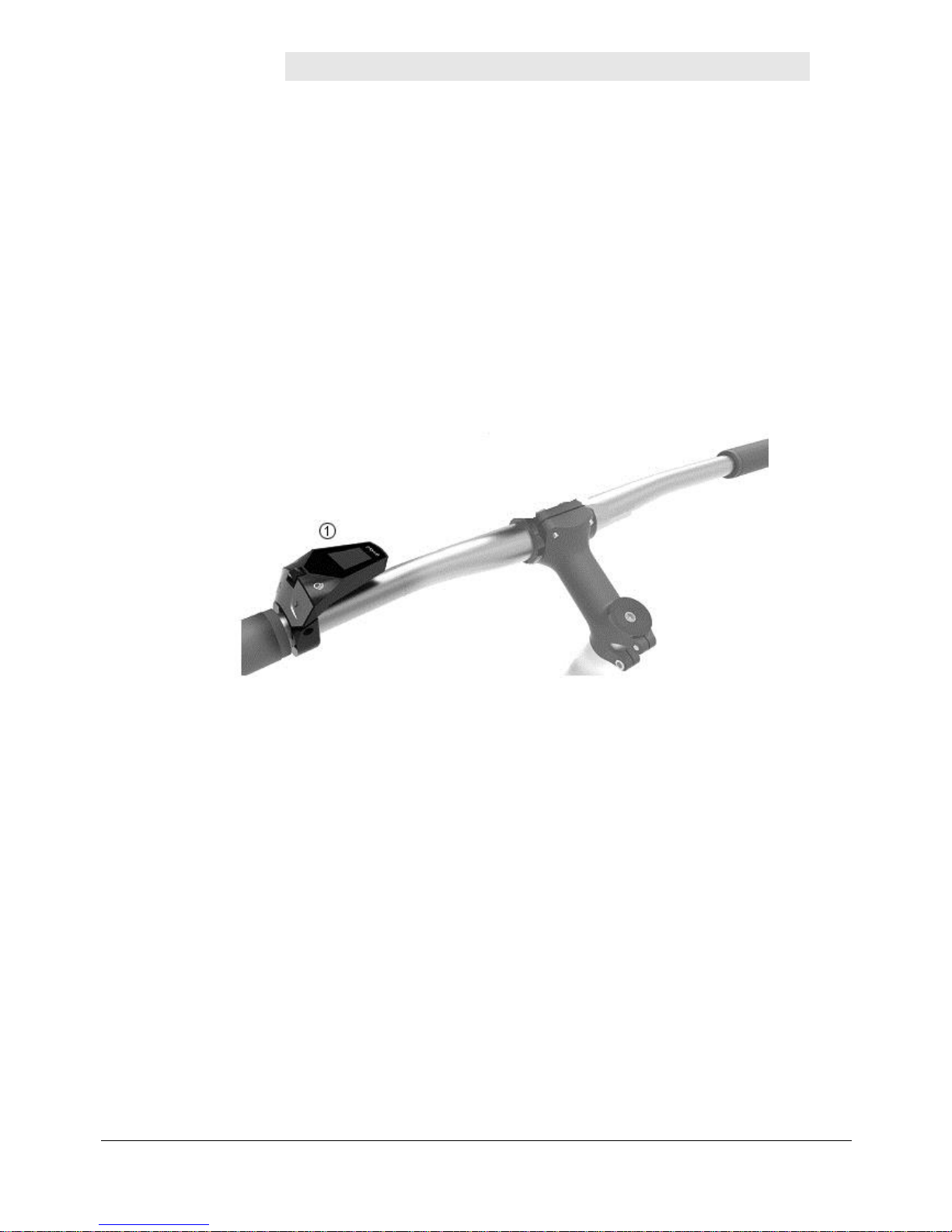
3.1 Components
Fig. 1 Components
1. Control Panel Comfort
3.2 Technical Data
Control Panel Comfort
Length x width x height
72.8 x 50.2 x 44.6 mm
Operating temperature
-10°C to 65°C
Storage temperature
-20°C to 85°C
Protection type
IP65 (HMI) dust-tight, spray protected
ESD Model
Human Body Model (HBM)
USB port
Micro USB Standard 2.0 Full Speed
USB charge function
USB Battery Charging Standard BC1.2 Max. 1.0 A
CAN Interface ISO 11898-5
High-speed CAN
Page 8

Mounting the Control Panel Comfort
8 Control Panel Comfort for Pedelecs
4 Mounting the Control Panel Comfort
Check the fastening screws regularly. Screws can loosen due to vibration, heat,
and cold temperatures.
Tighten all screws with the required torque.
The Control Panel Comfort is mounted on the left side of the handlebars. The protruding side
faces inward. It does not protrude past the handlebar grips. Position the operating unit close to
the grips. All buttons must be easy to operate with your thumb.
1. Use a size 2.5 hex socket to unscrew the hex screw on the operating unit bracket. Open
the mounting bracket.
2. Position the operating unit on the left side of the handlebar.
3. Position the connection cable in the operating unit bracket. It must be in the guide
grooves inside the bracket, and must be wired to the connection through the opening in
the bracket.
4. Close the bracket. Be careful not to damage the connection cable.
The connection cable may no be crushed by the bracket.
5. Use a size 2.5 hex socket to tighten the hex screw on the operating unit bracket. Do not
tighten the screw completely.
Check the position of the Control Panel Comfort. Can you reach all of the buttons with
your thumb? Is the display clearly visible?
6. Tighten the hex screw using the hex socket (min. torque 0.3 Nm, max. torque 0.5 Nm).
7. Connect the purple plug on the operating unit with the purple socket on the wiring harness. Ensure the openings on the socket and plug match up so as not to damage the
connection.
The Control Panel Comfort is now mounted.
Page 9

Control Panel Comfort for Pedelecs 9
5 Operating and Display Elements
You can use the buttons on the Control Panel Comfort to ergonomically control the functions of
the pedelec system. Your hand can remain on the handlebar while you operate the buttons on
the Control Panel Comfort using your thumb. The screens on the operating unit display provide
information on your riding situation and support aids.
If Display premium is connected, most information is displayed there. The buttons on the Control Panel Comfort remain active for easy to operate inputs.
5.1 Operating Buttons
You can use the buttons on the Control Panel Comfort to control the functions of the pedelec
system.
Fig. 2 Buttons and joystick on the Control Panel Comfort
Button
Function
T1
Increase support level
Hold > 3s: Activate pushing mode until the button is released.
T2
Reduce support level
T3
Joystick:
One page higher.
Switch to Editor mode.
One entry up in Editor mode.
Move left to next page.
Leave mode and confirm value in Editor mode.
Edit the highlighted value in Editor mode.
Move right to next page.
Leave mode and confirm value in Editor mode.
One page down.
Switch to Editor mode.
One entry up in Editor mode.
T4
Switch Control Panel Comfort on and off.
T5
Brief pressure: Switch light on.
Longer pressure: Switch light off.
In automatic mode: The light is switched on or off depending on the surrounding light
level. You can also switch the light on or off at any time using this switch.
Page 10

Operating and Display Elements
10 Control Panel Comfort for Pedelecs
5.2 Control Panel Comfort Display
The display of the Control Panel Comfort offers a variety of information on different pages.
Move the joystick side to side to switch between pages. Some of the pages offer additional
pages, which you can access by moving the joystick vertically.
The main page offers the following information:
1
Display of current support level.
2
Speed
3
Status display for
Triangle symbol: Pushing aid active.
Lighting: Symbols display the status.
4
Battery charge level.
The other pages are designed according to the following pattern:
1
Symbol for the page.
2
Horizontal navigation position.
3
Page content.
4
Vertical navigation position: Refers to other
pages and shows the current position.
Human Power
Fig. 3 Comfort page human power
Displays the power currently generated for the pedelec drive by the rider in watts.
Page 11

Control Panel Comfort for Pedelecs 11
Residual Range
Fig. 4 Comfort page residual range
Displays the residual range of the pedelec with support.
Tour Distance
Fig. 5 Comfort page tour distance
Displays the distance traveled since the value was last reset.
This page includes additional pages.
Tour Distance / Average Speed
Fig. 6 Comfort page tour average speed
Mean speed.
Displays the average speed for the current distance.
Page 12

Operating and Display Elements
12 Control Panel Comfort for Pedelecs
Tour Distance / Maximum Speed
Fig. 7 Comfort page tour max. speed
Maximum speed.
Displays the highest speed for the current distance.
Tour Distance / Reset
Fig. 8 Comfort page tour reset
Reset – Pressing the joystick marks the RESET button.
Pressing the joystick again resets the values to “0” for the tour.
The values for distance, average speed, and maximum speed are deleted and set to
“0.”
Total Distance
Fig. 9 Comfort page total distance
Displays the total distance traveled with the pedelec.
This display includes an additional page.
Page 13

Control Panel Comfort for Pedelecs 13
Total Distance / Maximum Speed
Fig. 10 Comfort page max. speed
Displays the highest speed reached by the pedelec over the entire distance.
Automatic Light
Fig. 11 Comfort page automatic light
Use this page to activate automatic mode for the headlight. The light will then be switched on or
off depending on the surrounding light level.
If automatic mode is activated, the headlight symbol will be displayed with an “A” on the main
page.
You can press the T5 button to switch the light on or off at any time.
6 Operations
6.1 Turning the Unit On and Off
Turning the Control Panel Comfort On
Press the T4 button for longer than 2s.
The display will show the start page, then switch to the main page.
Turning the Control Panel Comfort Off
Press the T4 button for longer than 2s.
The display will turn off.
Page 14

Operations
14 Control Panel Comfort for Pedelecs
6.2 Operations
6.2.1 Headlight
The T5 button is used to switch the light on or off. If automatic light control is activated, the light
will be switched on or off in response to the surrounding light level.
The main page displays the current status of the headlight using the following symbols:
Symbol
Headlight
-
Headlight off
Headlight on
Automatic mode on – headlight off
Automatic mode headlight on
Switch Headlight On
Press the T5 button briefly.
The headlight is switched on.
The headlight symbol displays normal light status.
Switch Headlight Off
Press the T5 button for longer than 2s.
The headlight is switched off.
The headlight symbol displays the current status.
Switch Headlight Automatic Mode On and Off
You can activate automatic mode for the headlight on the “Automatic light” page.
The automatic mode switches the headlight on and off in response to the surrounding light level.
You can switch the headlight on or off at any time in automatic mode by pressing the T5 button.
6.2.2 Adjust Support
The electric motor on your pedelec supports your pedaling power. Multiple support levels are
available. You can also ride without motor support.
Use the Control Panel Comfort to adjust the level of support (T4 / T2).
Comfort uses a scale to display the current support level.
Once you select a level, it is activated immediately.
The illuminated segments on the support display on the main page of the Control Panel Comfort
display the active level.
Page 15

Control Panel Comfort for Pedelecs 15
Level
Description
None
Normal cycling conditions. Motor not active.
ECO
Efficient support for maximum battery range
NORMAL
Even support for long distances with long battery
range
HIGH
Powerful support for sporty riding, on mountainous
terrain, and in city traffic with normal battery range
Activate Support
The display does not show any support level.
1. Press the T1 button on the Control Panel Comfort.
The electric motor activates to support riding.
The first segment is illuminated on the support display.
Increasing Support
1. Press the T4 button. You will switch to the next higher level.
The electric motor will provide additional riding support.
Additional segments are illuminated on the support display.
Reducing Support
1. Press the T2 button.
The electric motor will provide less riding support.
The number of segments illuminated on the support display will be reduced.
Riding Without Support
1. Press the T2 button until no segments are visible on the support display.
You will ride without motor support.
6.2.3 Pushing Aid
The pushing aid is available for starting riding or for pushing the bicycle. The pedelec drive supports the bicycle's movement. The pushing aid can be activated up to a speed of < 6 km/h.
Use the pushing aid when pushing the bicycle, when starting riding, or for supported start-up on
mountainous terrain. Push the bicycle, walking beside it. Use the pushing aid as a start-up aid
when you are sitting on the bicycle.
In both cases, the pushing aid will move the pedelec when activated.
Page 16

Operations
16 Control Panel Comfort for Pedelecs
WARNING!
The pushing aid will move the pedelec.
Hold the handlebar grip and be ready to brake.
Sit on the bicycle and do not press the pedals. Your pushing force, combined
with the pushing aid, could accelerate the pedelec very quickly. The second pedal will also move, and can injure you when getting on the bike!
Do not use the pushing aid for slow riding.
Activate Pushing Aid:
Press and hold the T4 button.
The pushing aid is active and moves the bicycle.
The main page of the display shows the triangular symbol for the pushing aid.
Deactivate Pushing Aid:
Release the T4 button.
The pushing aid will be deactivated.
The triangular symbol for the pushing aid will no longer be shown on the main page.
6.3 USB Port
The Control Panel Comfort has a micro USB AB plug. The USB plug is located in the tip of the
device over the handlebar, and is protected against dirt and moisture with a rubber cap.
Fig. 12 USB connection
Page 17

Control Panel Comfort for Pedelecs 17
Connect USB Device
NOTE!
For damage to the mobile phone caused by the connection to the control unit
Comfort there is no liability.
1. Open the protective rubber cap on the USB connection.
2. Connect the USB device to the USB port – either directly or using a suitable USB cable.
The new connection is displayed on the connected device.
Remove USB Device
NOTE!
Observe the information for interrupting the USB connection in the operating
manual for the connected device.
1. Remove the USB device or connection cable from the USB port on the Control Panel
Comfort.
2. Cover the USB port with the protective rubber cap.
NOTE!
The control unit Comfort is protected against water and dirt only when the rubber protection is closed.
Page 18

Error Codes
18 Control Panel Comfort for Pedelecs
7 Error Codes
The Control Panel Comfort displays error codes for the entire pedelec system. Error codes represent errors recognized by the system. The following table provides the meanings of these error codes. Please note the recommended reactions to error codes.
WARNING!
Pay attention to error codes!
Error codes can indicate serious faults in the pedelec system. These errors pre-
vent safe operation of the pedelec. They may result in personal injury or damage to the pedelec.
Stop riding the pedelec. Determine the meaning of the error code and observe
the recommendations to correct the error.
If you are not certain what the error code means, stop riding and park your bicycle. Contact the manufacturer, retailer, or your workshop for information on what
to do next.
Error code
Description
Solution approach
10
The Battery voltage is too low.
Charge the battery pack using the battery charger.
11
The Battery voltage is too high.
Switch off the system completely and then back on
using the Control Panel button T4. If the problem
persists, contact your e-bike dealer.
12
The battery is almost / completely discharged.
Charge the battery pack using the battery charger.
20
Electrical measurements are incorrect.
Switch off the system completely and then back on
using the Control Panel button T4. If the problem
persists, contact your e-bike dealer.
21
Thermal sensor defective.
24
The Internal voltage is outside of the
working range.
Charge the battery pack using the battery charger.
25
Error in motor current measurement.
Switch off the system completely and then back on
using the Control Panel button T4. If the problem
persists, contact your e-bike dealer.
26
A software reset was completed.
40/41
Overcurrent in the motor.
Reduce the load on the motor by pedaling less or
by reducing the assist level.
42
Fault in motor rotation.
Switch off the system completely and then back on
using the Control Panel button T4. If the problem
persists, contact your e-bike dealer.
43
Short circuit in motor.
Page 19

Control Panel Comfort for Pedelecs 19
Error code
Description
Solution approach
44
Overheating of motor.
Reduce the load on the motor by pedaling less or
by reducing the assist level.
45
The software has corrected an error in
motor rotation.
Switch off the system completely and then back on
using the Control Panel button T4. If the problem
persists, contact your e-bike dealer.
46
No motor movements recognized.
60
Interruption to data exchange on the
CAN-BUS.
Check the cables and plug connections of all components of the e-bike system.
70
Force applied to pedal not in valid range.
Switch off the system completely and then back on
using the Control Panel button T4. If the problem
persists, contact your e-bike dealer.
71
Turning of pedals not detected.
72
Force applied to pedal not detected.
73
The connection to the pedal force sensor
has been interrupted.
74
Errors were found in the data.
80
Incorrect motor parameter.
Switch off the system completely and then back on
using the Control Panel button T4. If the problem
persists, contact your e-bike dealer.
81
Speed signal not recognized.
Ensure that the spoke magnet is correctly positioned relative to the speed sensor.
82
The program was manipulated.
Switch off the system completely and then back on
using the Control Panel button T4. If the problem
persists, contact your e-bike dealer.
83
Error in program sequence.
84
Incorrect motor parameter.
Page 20

Disposal
20 Control Panel Comfort for Pedelecs
8 Disposal
In accordance with European directive 2012/19/EU covering non-functional
electrical devices, and in accordance with European directive 2006/66/EC
covering used batteries, devices and batteries must be collected separately
and sent for environmentally-appropriate recycling.
Old machinery, replacement parts, and packaging are made of recyclable
materials. The owner is obligated to dispose of these properly and in an
environmentally-friendly manner in accordance with legal requirements.
All injection-molded plastic components are marked with a recycling symbol.
RoHS directive (2011/65/EU)
Page 21

Control Panel Comfort for Pedelecs 21
Page 22

Control Panel Comfort for Pedelecs
 Loading...