

Page 1

Annex No.5
Technical Description
Users Manual
Page 2

Annex No.5
Technical Data
HF-part
Basic Key
3317
Software status: V5.1
Hardware status: V1.3
Mechanical status: V3.2
with mechanical emergency key
Author : D. Weisser
Department: AE12
Tel. : +49(0)7424/99-1601
Fax. : +49(0)7424/99-2541
E-mail : dietmar.weisser@marquardt.de
Date published: 01.03.04
Revision status
Version : 01
Page 3

Annex No.5
Functional description:
The basic design key is one of the components of a driver authorisation system and has the
following functions:
1.) Remote control for vehicle access (German abbreviation FZB) via radio and infrared
signals
2.) Driver authorisation (engine start-up) once the key has been inserted into the electronic1
ignition and steering lock
For 1.) a message is sent to the vehicle by the key via an HF transmitter once a button has been
pressed on the key.
2
For 2.) bi-directional communication
place using infrared light. The electronic ignition and steering key produces an inductive field
of 125 kHz for the key power supply.
between the key and the ignition and steering lock takes
Page 4

Annex No.5
General technical data:
Temperature range:
Working temperature: -20 ...+65 ° C
Data of the HF-part
Type of data transmission: uni-directional (transmit only)
Transmitter:
Transmitting frequency: 433.92 MHz (ECE)
315.00 MHz (USA)
315.00 MHz, backed-off (Japan)
Transmitting frequency tolerance: +/- 75 ppm
(production, aging, temperature)
Transmitting capacity (EIRP): typical -18 dBm ( < -15 dBm) @433.92 MHz
typical -18 dBm ( < -15 dBm) @315.00 MHz
(USA)
typical < -40dBm @315MHz (Japan)
Modulation: Frequency shift keying ( 2-FSK)
Frequency shift: +/- 15 ...+/-17 kHz, nominal: +/- 16 KHz
Modulation content: digital data
Data rate: 1 kBit/s (remote control)
Coding: Manchaster3
Data contents: Remote control (1 Kbit/s):
55 zero bits (preamble + 1 start bit + 112 bit data)
Data burst rate: Remote control: max.10 000/a
Page 5
Annex No.5
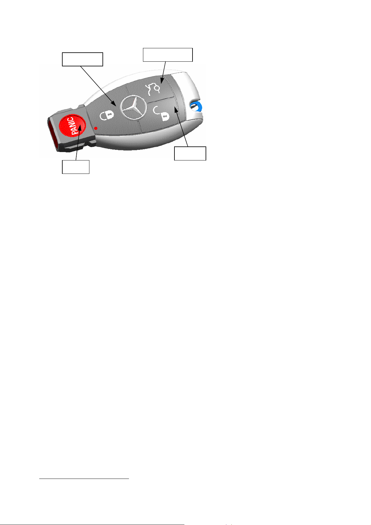
Lock
Tailgate
Unloc
Panic
Activating test modes on the Keyless Go4
Button 1: Unlock
Button 2: Tailgate/boot lid (not applicable for estate vehicles)
Button 3: Lock
Button 4: Panic (USA version)
Mechanical emergency key inside housing and latched in place
Page 6

Annex No.5
Key: (set permanently to HF diagnosis 1, see marking)
The operating mode is switched on and off alternately by briefly pressing the respective button (LED
flashes!)
HF diagnosis 1:
Button Diagnosis operating mode
Unlocking button (Button 1) Transmit low transmission frequency (non-modulated)
Locking button (Button 3) Transmit upper transmission frequency (non-
modulated)
Tailgate (Button 2) Transmit data telegram at 1kbBit
Page 7

Annex No.5
Technical Data
HF-part
Keyless Go
3317
Software status: V3.5
Hardware status: V2.3 [KW03/04]
Mechanical status: V3.2 [51/03]
with mechanical emergency key
Author : U. Schwalm
Department: AE12
Tel. : 07424/99-1975
Fax. : 07424/99-2541
E-mail: uwe.schwalm@marquardt.de
Date published: 12.02.04
Revision status:
Version : 01
Page 8

Annex No.5
Functional description:
The design key is one of the components of a driver authorisation system and has the following
functions:
2.) Remote control for vehicle access (German abbreviation FZB) via radio and infrared
signals
3.) Keyless Go vehicle access
4.) Keyless Go driver authorisation (engine start-up, key search)
For 1.) a message is sent to the vehicle by the key via an HF transmitter once a button has been
pressed on the key.
For 2.) and 3.) bi-directional data communication takes place between key and vehicle via an
HF transceiver. The communication is started by the vehicle when one of the operating
elements on the door or boot is triggered.
In case 3.), when the vehicle is moving and every time the vehicle is started up, data
communication with the key takes place. This is started from the vehicle.
The key is fitted with a receiver for an inductive, low-frequency field (19.1 kHz). When a
certain data pattern is being transmitted on this frequency by the vehicle, the key is prepared
for the data communication state (wakes up from stand-by). As the functional process
progresses, the key also evaluates the receiving strength of the above-mentioned inductive field
for non-modulated transmission.
Page 9

Annex No.5
General technical data:
Temperature range:
Working temperature: -20 ...+65 ° C
Data of the HF-part
Type of data transmission: half duplex
Transmitter:
Transmitting frequency: 433.92 MHz (ECE)
315.00 MHz (USA)
Transmitting frequency tolerance: +/- 30 ppm
(production, aging, temperature)
Transmitting capacity (EIRP): typical -18 dBm ( < -15 dBm) @433.92 MHz
typical -18 dBm ( < -15 dBm) @315.00 MHz
(USA)
Modulation: Frequency shift keying (2-FSK)
Frequency shift: +/- 15 ...+/-17 kHz, nominal: +/- 16 KHz
Modulation content: Digital data
Data rate: 1 kBit/s (remote control)
10 kBit/s (Keyless Go)
5
Coding: Manchaster
Data contents: Remote control (1 Kbit/s):
55 zero bits (preamble + 1 start bit + 112 bit data)
Keyless Go (10 kBit/s)
12 zero bits (preamble) + 1 start bit + max. 96 Bit
data
Data burst rate: Remote control: max.10 000/a
Keyless Go: max. 100 000/a at
performance of 100 000 km/a
Page 10

Receiver 1:
Receiving frequency: 433.92 MHz (ECE)
315.00 MHz (USA)
Average receiving frequency tolerance: +/- 35 ppm
(production, aging, temperature)
Receiving bandwidth: 270kHz
Receiving sensitivity: ≤ –76 dBm (with aerial)
Demodulator output: FSK2 (-16 KHz Low, +16 KHz High)
Receiving data rate: 10 kBit/s
6
Coding: Manchaster
Receiver 2 (inductive):
Receiving frequency: 19.1 kHz +/-1kHz
Demodulator output: ASK/OOK-Demodulation
Receiving data rate: 1.365 kBit/s
Data burst: 16 data bits
Lock
Tailgate
Annex No.5
Unloc
Panic
Activating test modes on the Keyless Go
Button 1: Unlock
Button 2: Tailgate/boot lid (not applicable for estate vehicles)
Page 11

Button 3: Lock
Button 4: Panic (USA version)
Mechanical emergency key inside housing and latched in place
Annex No.5
Page 12

Annex No.5
Key: (set permanently to HF diagnosis 1, see marking)
The operating mode is switched on and off alternately by briefly pressing the respective button
HF diagnosis 1:
Button Diagnosis operating mode
Unlocking button (Button 1) Transmit low transmission frequency (non-modulated)
Locking button (Button 3) Transmit at 1 kHz permanent modulation
Tailgate (Button 2) Transmit at 10 kHz permanent modulation
Key: (set permanently to HF diagnosis 2, see marking)
The operating mode is switched on and off alternately by briefly pressing the respective button
HF diagnosis 2:
Button Diagnosis operating mode
Unlocking button (Button 1) Permanent receiving mode
Locking button (Button 3) Transmit upper transmission frequency (non-
Tailgate (Button 2)
modulated)
Transmit data burst with 10 kBaud Manchaster
7
*
Page 13

* 12 pre-impulses + 24 data bits (48h, 53h, AEh), break between the data burst 1ms,
in receiving mode during break in transmission.
The receiver for 19.1 kHz is in permanent receiving mode independent of any settings on the
key.
Annex No.5
Page 14

Page 15

Page 16

Page 17

 Loading...