

Page 1
www.maroomcs.com
Chapter 1. Battery Management System
1-1 SYSTEM DIAGRAM
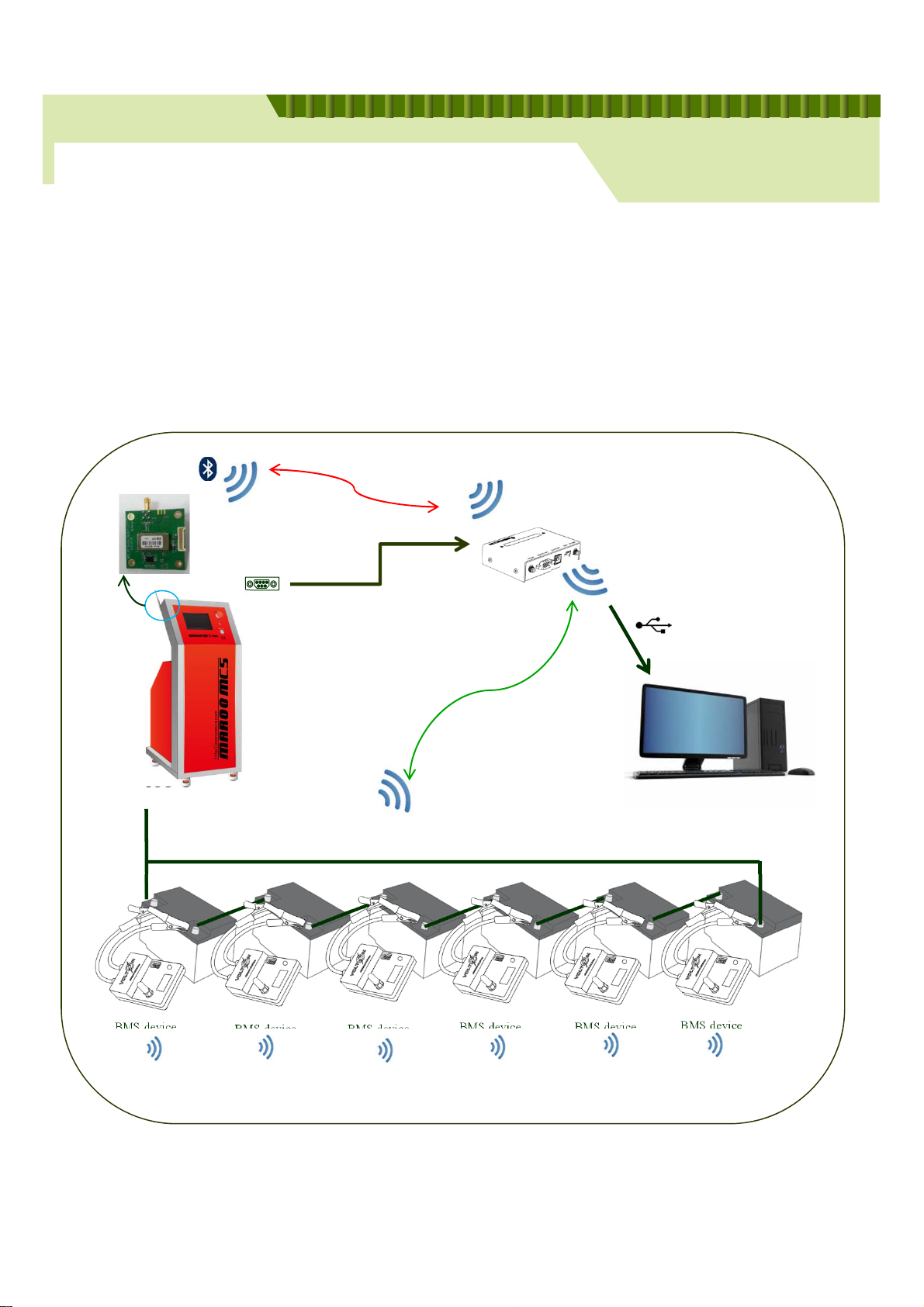
Through Battery Management System(BMS) the progress of battery restoration or discharge can be
figured out. It is consist of BMS Device, Integration Receiver and Integrated Monitoring Program.
This chapter will be described about BMS Device and Integration Receiver. The next chapter will be
described for Integrated Monitoring Program.
Battery Regenerator
[SYSTEM DIAGRAM]
Bluetooth
2.4GHz Wireless
MCS
2ADECMCS-BTD-001
Serial
Serial Cable
Connection
2.4GHz Zigbee Wireless
Bluetooth
Integration Receiver
2ADECMCS-IR-001
USB
Connection
2.4GHz Zigbee Wireless
PC with Integrated Monitoring Program
BMS device
BMS deviceBMS device
Battery with BMS Device
65
BMS deviceBMS device
( Example for restoration of 6 batteries at once)
BMS device
Page 2

www.maroomcs.com
Chapter 1. Battery Management System
1-2 FCC Certification Requirements
Caution: Any changes or modifications in construction of this device which are not expressly
approved by the party responsible for compliance could void the user's authority to operate
the equipment.
This device complies with part 15 of the FCC Rules. Operation is subject to the following two
conditions: (1) This device may not cause harmful interference, and (2) This device must accept any
interference received, including interference that may cause undesired operation.
NOTE: The manufacturer is not responsible for any radio or TV interference caused by
unauthorized modifications to this equipment. Such modifications could void the user’s authority
to operate the equipment.
NOTE: This equipment has been tested and found to comply with the limits for aClassB
digital device, pursuant to part 15 of the FCC Rules. These limits are designed to provide reasonable
protection against harmful interference in a residential installation. This equipment generates uses and
Battery Regenerator
can radiate radio frequency energy and, if not installed and used in accordance with the
instructions may cause harmful interference to radio communications.
However, there is no guarantee that interference will not occurin a particular installation.
If this equipment does cause harmful interference to radio or television reception, which can be
determined by turning the equipment off and on, the user is encouraged to trytocorrect
the interference by one or more of the following measures:
- Reorient or relocate the receiving antenna.
- Increase the separation between the equipment and receiver.
-Connect the equipment into an outlet on a circuit different from that to which the receiver is
connected.
-Consult the dealer or an experienced radio/TV technician for help.
65
Page 3

www.maroomcs.com
Chapter 1. Battery Management System
1-2 FCC Certification Requirements
WARNING: This equipment may generate or use radio frequency energy. Changes or
modifications to this equipment may cause harmful interference unless the modifications are expressly
approved in the instruction manual. The user could lose the authority to operate this equipment if an
unauthorized change or modification is made.
This device complies with Part 15 of the FCC rules. Operation is subject to following two conditions: 1.
this device may not cause harmful interference and 2. This device must accept any
interference received including interference that may cause undesired Operation of this device.
The changes or modifications not expressly approved by the party responsible for Compliance could
void the user’s authority to operate the equipment.
To comply with the FCC RF exposure compliance requirements, this device and its antenna must
not be co-located or operating to conjunction with any other antenna or transmitter, except if installed
in compliance with FCC Multi Transmitter procedures.
Battery Regenerator
To inherit the modular approval, the antennas for this transmitter must be installed to provide a
separation distance of 20cm from all persons and must not be co-located or operating in Conjunction
with any other antenna or transmitter.
Note: This equipment has been tested and found to comply with the limits for a Class B digital device,
Pursuant to part 15 of the FCC Rules.
These limits are designed to provide reasonable Protection against harmful interference in a residential
installation. This equipment generatesUsesandcanradiateradiofrequency energy and, if not
installed and used in accordance With the instructions, may cause harmful interference to
radio communications.
However, there is no guarantee that interference, Will not occur in a particular installation.
If this equipment does cause harmful interference to radio or television reception, which can be
determined by turning the equipment off and on, the user is encouraged to trytocorrect
the interference by one or more of the following measures:
- Reorient or relocate the receiving antenna.
- Increase the separation between the equipment and receiver.
- Connect the equipment into an Outlet on a circuit different from that to which the
receiver is connected
65
Page 4

www.maroomcs.com
Chapter 1. Battery Management System
1-2 FCC Certification Requirements
To OEM Installer
1. FCC ID on the final system must be labeled with
“Contains FCC ID: 2ADECMCS-IR-001, 2ADECMCS-BTD-001” and
“Contains transmitter Module FCC ID: 2ADECMCS-IR-001, 2ADECMCS-BTD-001“
2. In the user manual, final system integrator must ensure that there is no instruction provided in the
user Manual to install or remove the transmitter module.
3. Transmitter module must be installed used in strict accordance with the Manufacturer’s instructions
as described in the user documentation that comes with the product. The usermanualofthe
final host system must contain the following statements: This device complies with Part 15 of the FCC
rules. Operation is subject to following
Two conditions: 1. this device may not cause harmful interference and 2. This device Must accept any
interference received including interference that may cause undesired operation of this device.
Battery Regenerator
The changes or modifications not expressly approved by the party responsible for Compliance could
void the user’s authority to operate the equipment.
To comply with the FCC RF exposure compliance requirements, this device and its antenna must
not be co-located or operating to conjunction with any other antenna or transmitter, except if installed
In compliance with FCC Multi Transmitter procedures.
To inherit the modular approval, the antennas for this transmitter must be installed to provide a
Separation distance of at least 20cm from all persons and must not be co-located or
operating in Conjunction with any other antenna or transmitter.
Note:
The buyer of the module who will incorporate this module into his host must submit the final product
to the Manufacturer of the module and the MANUFACTURER OF THE MODULE WILL VERIFY that the
product is incorporated in host equipment in a way that is represented by thetestingasshowninthe
test report.
Note:
The module is used MCS System.
65
Page 5

www.maroomcs.com
Chapter 1. Battery Management System
1-2 FCC Certification Requirements
FCC RF Radiation Exposure Statement
This equipment complies with FCC RF radiation exposure limits set forth for an uncontrolled
environment. This device and its antenna must not be co-locatedor operating in conjunction with any
other antenna or transmitter.
“To comply with FCC RF exposure compliance requirements, this grant is applicable to only Mobile
Configurations. The antennas used for this transmitter must be installed to provide a separation
distance of at least 20 cm from all persons and must not be co-located or operating in conjunction
with any other antenna or transmitter.”
Manual Information to the End User
The OEM integrator has to be aware not to provide information tothe end user regarding how to
install or remove this RF module in the user’s manual of the end product whichintegratesthismodule.
The end user manual shall include all required regulatory information/warning as show in this manual.
Battery Regenerator
Note:
1. The module is limited to OEM installation ONLY.
2. The module is limited to installation in mobile or fixed applications.
3. Separate approval is required for all other operating configurations, including portable configuration
with respect to Part 2.1093 and different antenna configuration.
65
Page 6
Chapter 1. Battery Management System
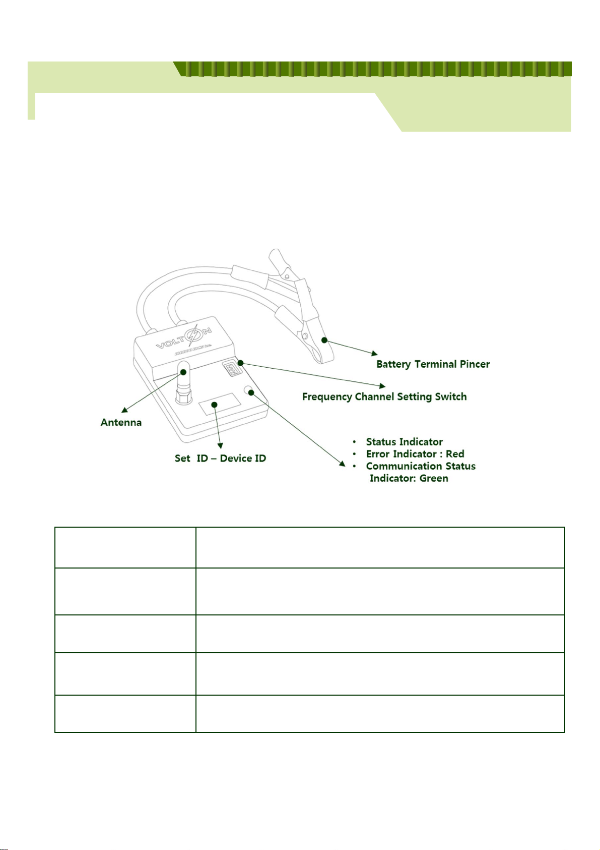
1-3 BMS device(Option)
BMS Device is connected with each battery cell and used for check the progress easily
when restoring more than 2 batteries. All data of BMS Device will be collected through
Integration Receiver.
www.maroomcs.com
Battery Regenerator
Battery Terminal Pincer
Frequency Channel Switch
Set ID – Device ID
Antenna
Status Indicator
Red Terminal Pincer – Positive(+) pole
Black Terminal Pincer – Negative(-) pole
Frequency Channel Switch to communicate with Integrated Receiver
( 2.5GHz Zigbee Communication)
Identity of Battery
Antenna for communicate with Integrated Receiver
Communication indicator with Integrated Receiver
Green ramp – success / Red ramp – Fail
56
Page 7
Chapter 1. Battery Management System
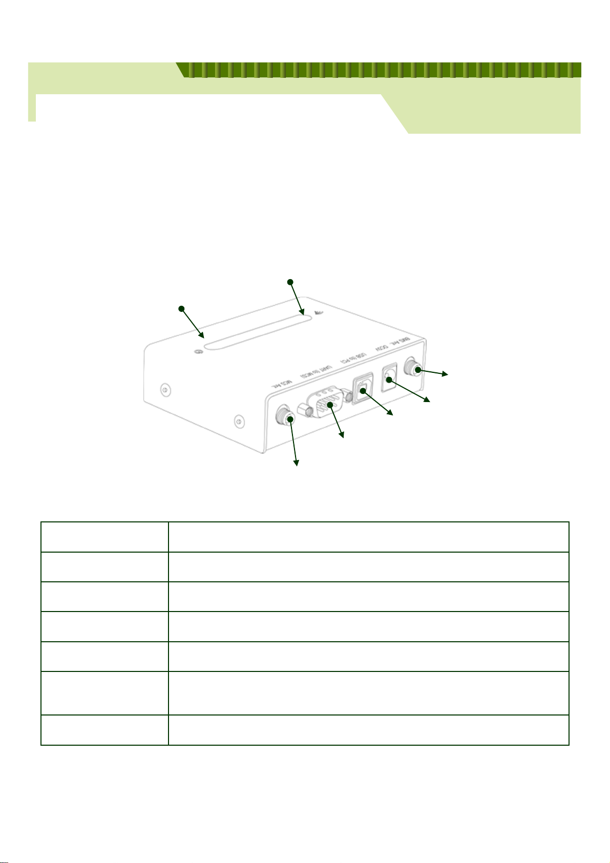
1-3 Integration Receiver
Integration Receiver has 2 functions below.
1 : Send BMS data to PC via Zigbee communication
2 : MCS Control via Bluetooth or Serial communication
Integration Receiver(MCS Communication)
Status Indicator(Power)
www.maroomcs.com
Battery Regenerator
BMS Antenna
DC 5V
USB Port (Common)
Serial Port(MCS)
Bluetooth Antenna(MCS)
BMS Antenna
DC 5V
USB Port (Common)
Serial Port(MCS) Serial communication between Integration Receiver and MCS
MCS Antenna
Integration Receiver
(MCS Communication)
Zigbee Antenna to communicate Integration Receiver and BMS
Reserve power supply by USB automatically
PC connection
Bluetooth Antenna between Integration Receiver and MCS
Blue ramp when Bluetooth connected between Integration Receiver and MCS
Status Indicator(Power)
Display power supply of Integration Receiver from PC
60
Page 8
Chapter 1. Battery Management System
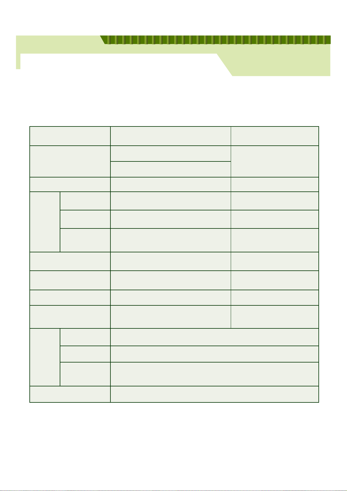
1-4 SPECIFICATION
2V BMS Device and Integration Receiver
ITEM BMS device Integration Receiver
2V 1.6~5V
INPUT POWER(V DC)
12 7~18V
www.maroomcs.com
Battery Regenerator
5V
Current Consumption
(mA)
CPU
Commun
ication
Antenna 1 dBi Dipole Antenna 4.5 dBi Dipole Antenna
Connector Banana Jack, Pincer-Cable Ass'y) USB, 6mm DC JACK, DB9
Inverse voltage General Diode in a row N/A
Dimension(W, D, H) 80 X57 X 15 mm
Zigbee
Interface 2.4GHz Zigbee RF USB, UART
OS Window XP, Win7
(18 Bit ADC, 12 Bit DAC)
Max 150 Max 250
MG2470
MG2470 MG2470
CANTUS
PC SW
Usage Temperature(℃) -20 ~ 60
RAM 1 GB ~
Requirement .net framework 4.0 ~
61
Page 9

www.maroomcs.com
Chapter 2. PC Integrated Monitor Program
2-1 Integrated Monitor Program
PC Program, Integrated Monitor is used for these usage with Integration Receiver .
- MCS Control
- Simple Data management
- Check data progress of each battery ( Option: when using BMS Device )
Battery Regenerator
Apply Integrated Monitor Program to control MCS, BMS Device
① Control MCS only
② Control BMS Device only
③ Control MCS and BMS Device together during discharge
Through PC Monitor Program it is possible to control MCS efficiently and save Log file at PC.
62
Page 10
Chapter 2. PC Integrated Monitor Program
2-2 Program Installation and Start
Installation
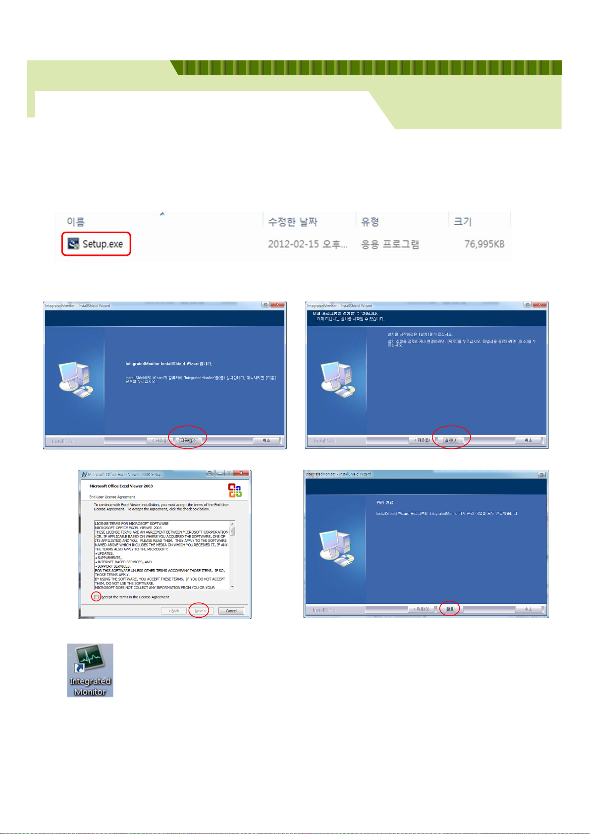
Installation program, “Setup. exe” is included in CD provided with MCS.
www.maroomcs.com
Battery Regenerator
Create Icon “Integrated Monitor” at wallpaper
10
Page 11
Chapter 2. PC Integrated Monitor Program
2-2 Program Installation and Start
Main Window
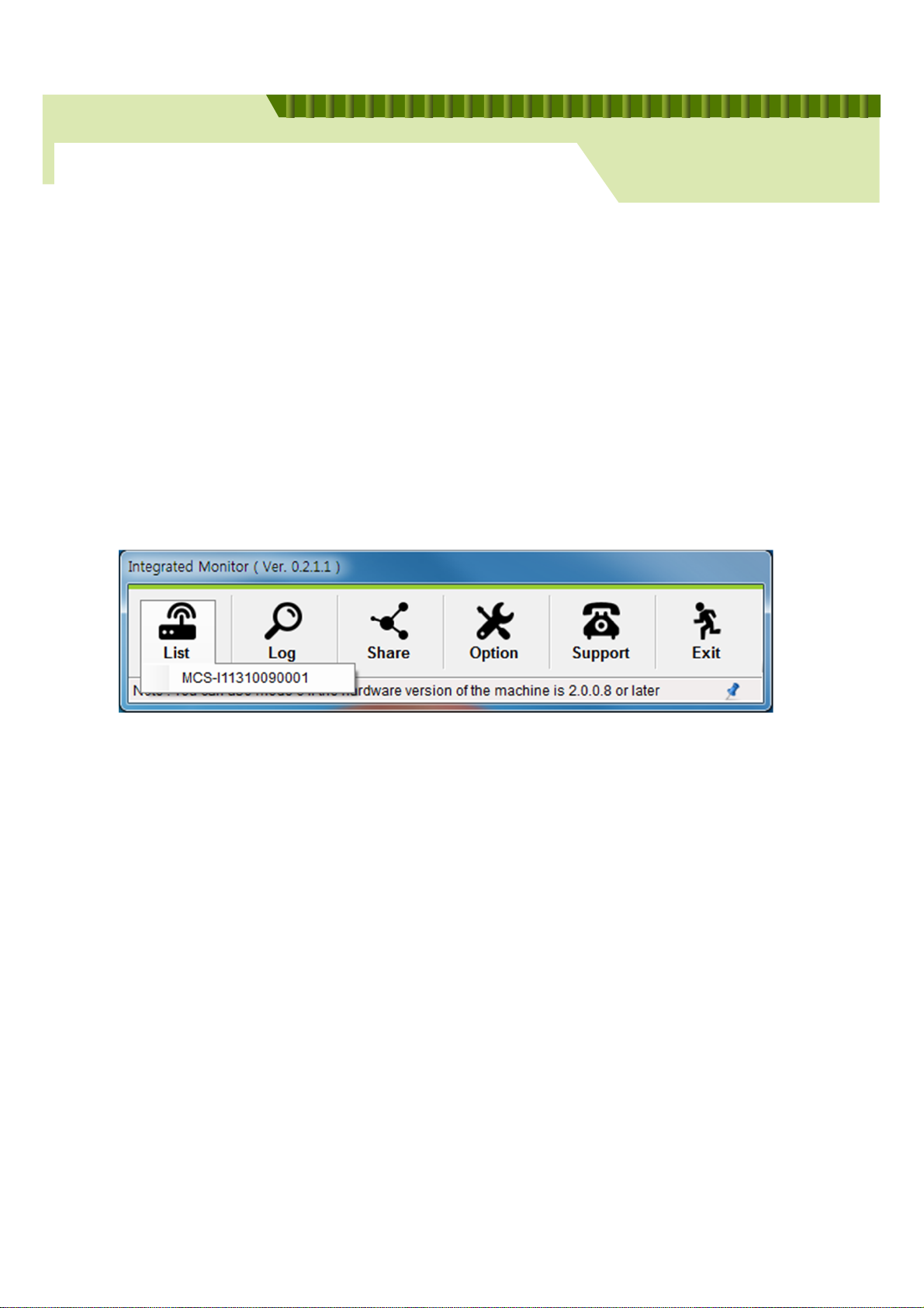
Connect with Integrated Receiver
Before using BMS, please connect integrated receiver first.
Click the list button, and choose the product number of integrated receiver.
www.maroomcs.com
Battery Regenerator
11
Page 12
Chapter 2. PC Integrated Monitor Program
2-2 Program Installation and Start
Control Window
www.maroomcs.com
Battery Regenerator
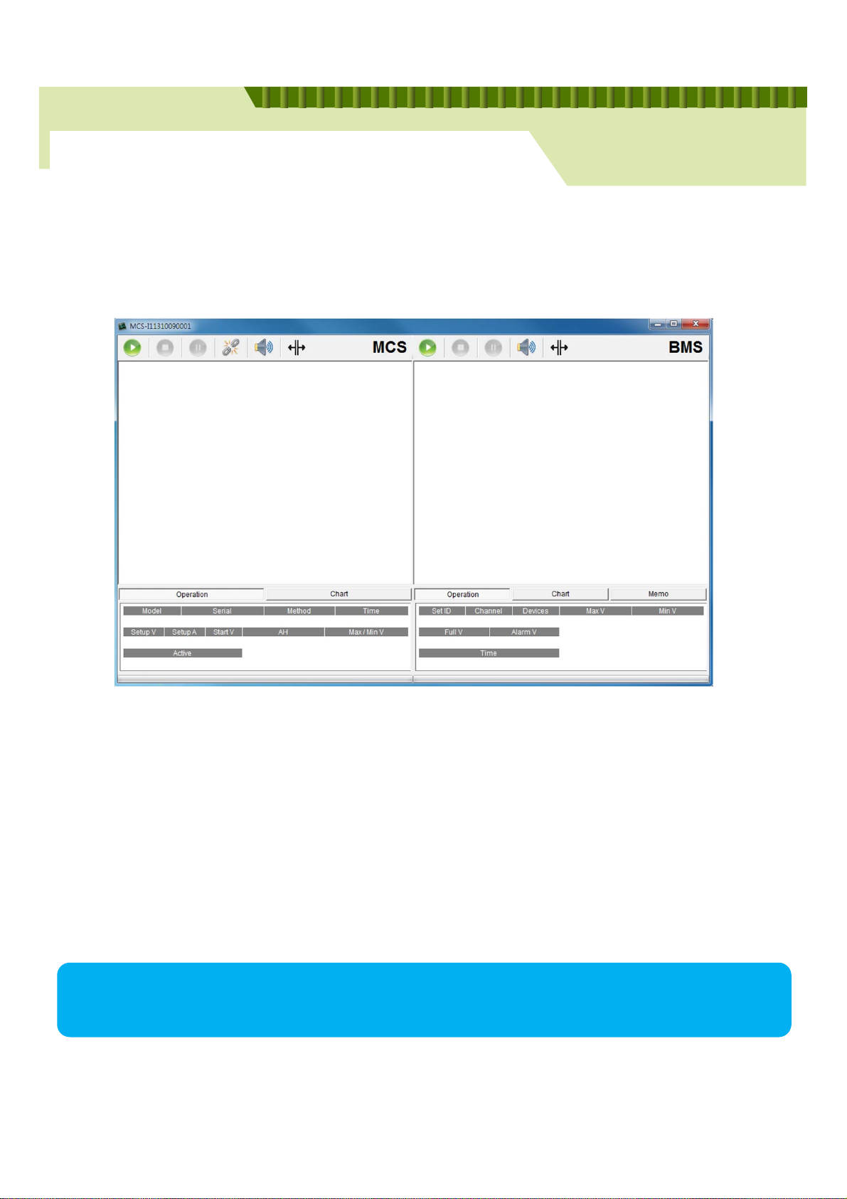
- Left panel : MCS , Right panel : BMS
- Bottom Box : operation information
- Top Buttons : Start , Stop, Pause, Sync, Enable Sound, Split Button
Integration Server is connected with MCS one on one.
12
Page 13
Chapter 2. PC Integrated Monitor Program
2-2 Operate
Operate MCS
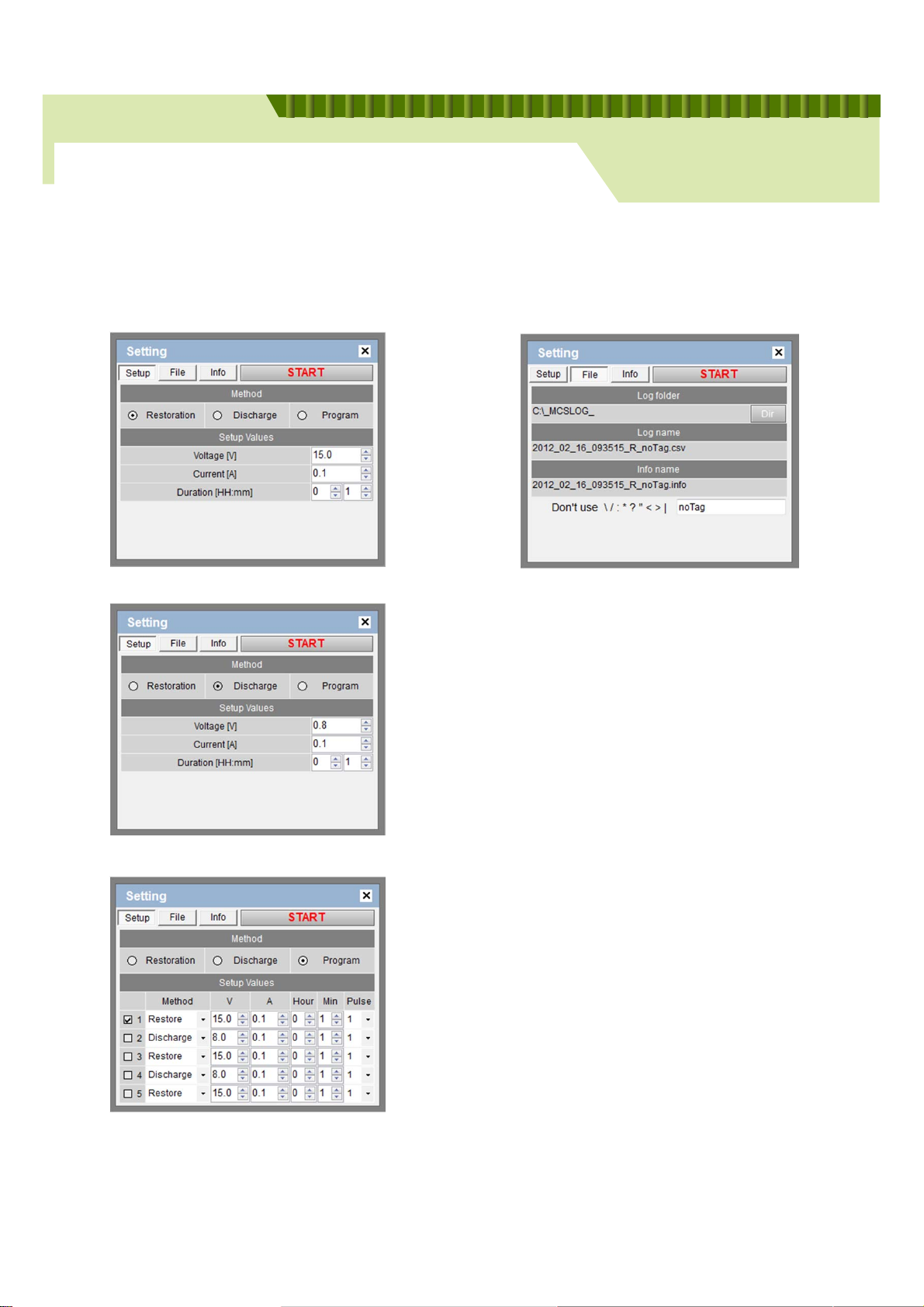
⑩ Pop up window for setting. Click “start” after input setting data.
www.maroomcs.com
Battery Regenerator
[Manual-Restoration Setting]
[Manual-Discharge Setting]
[Set Folder to save Log file]
[Tip]
Tag will help you to find Log File saved.
[Program Setting]
13
Page 14
Chapter 2. PC Integrated Monitor Program
2-2 Operate
Operate MCS
www.maroomcs.com
Battery Regenerator
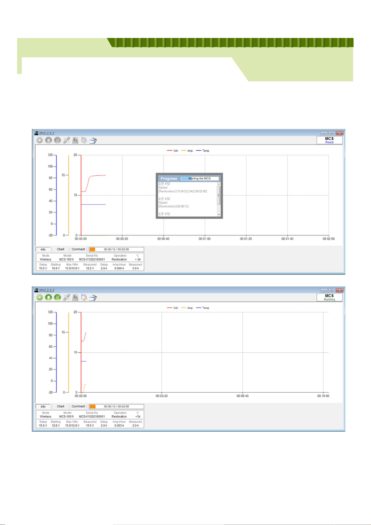
[Example for progress of MCS]
14
Page 15
Chapter 2. PC Integrated Monitor Program
2-2 Operate
Operate MCS
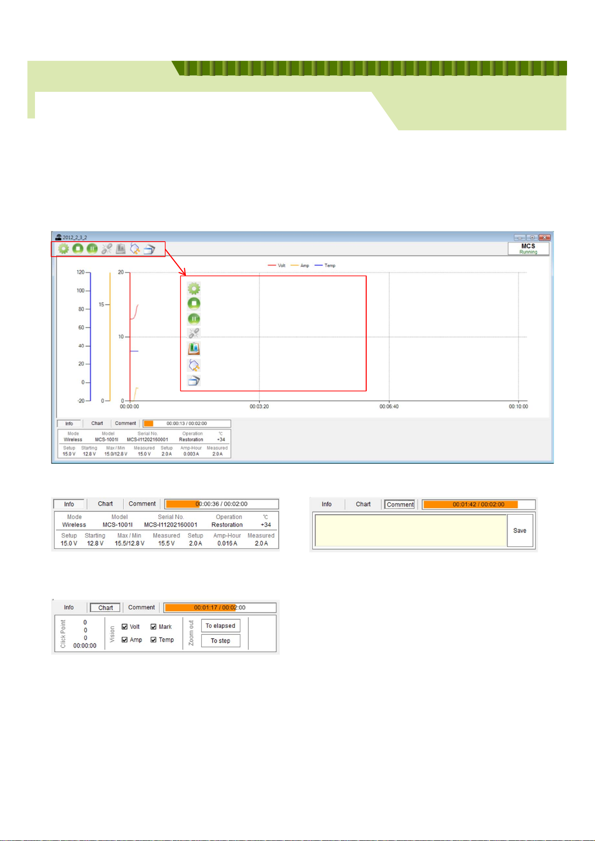
Description of the top menu of progress mode
Change setting value
Stop
Pause
Synchronizing MCS + BMS
Print Test Report
Re-connect Equipment
Switch window MCS <-> BMS
www.maroomcs.com
Battery Regenerator
Description on the bottom menu
• Information of MCS and operation
• Check Point : Check voltage, current, temperature, time on the check point
• Choose items to be shown on Graph
• To elapsed : Reduce graph by elapsed time
• To step : return to previous range
• Comment on Log file
Take a note, and Click Save
• When you bring the Log file you can find the
note in [Comment].
15
Page 16
Chapter 2. PC Integrated Monitor Program
2-2 Operate
Operate BMS
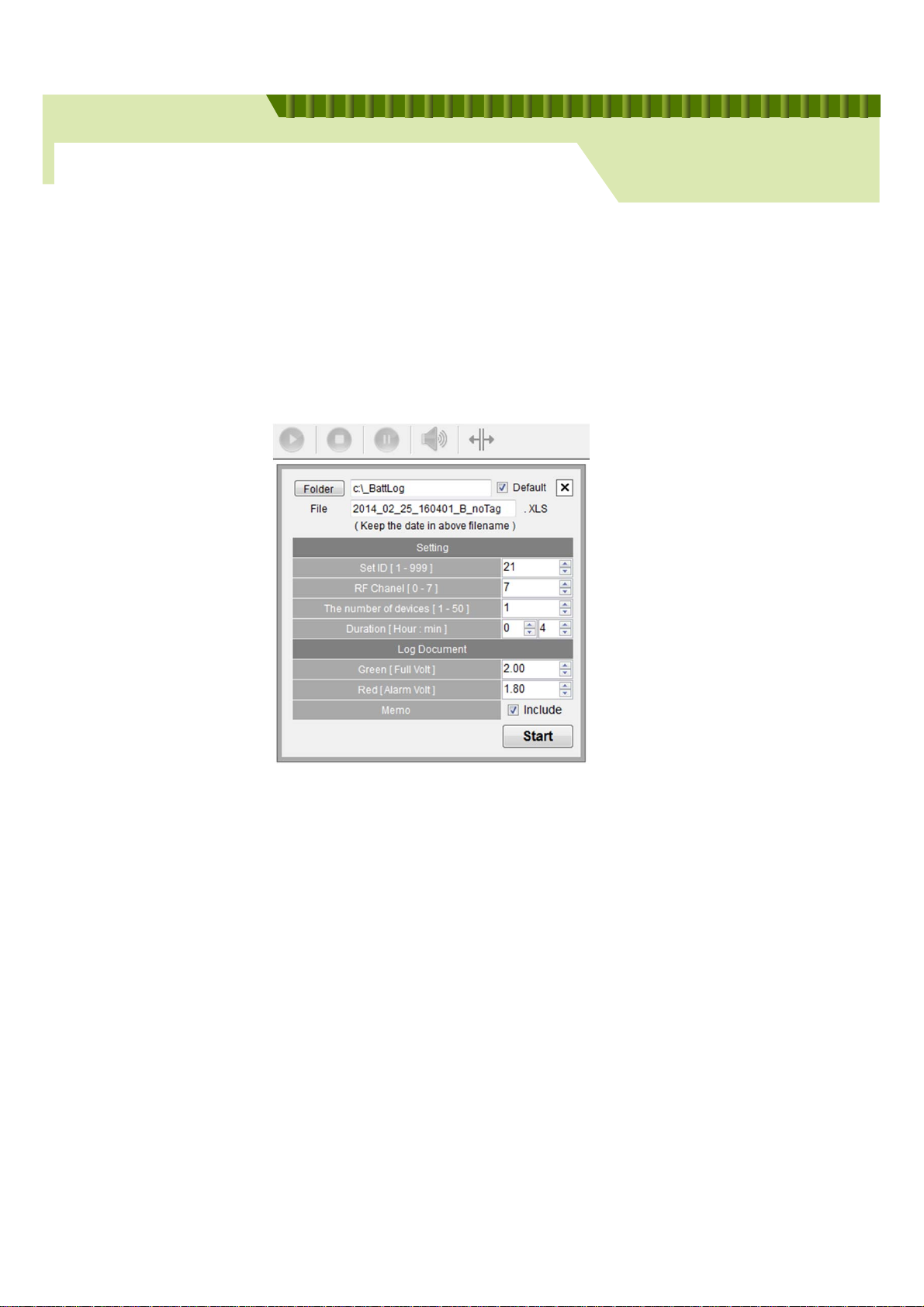
This popup will be shown after clicking start button. This is setup for starting.
www.maroomcs.com
Battery Regenerator
- Set ID (1~999) – input same amount as device label.
- RF Channel (0~7) – input same as set frequency channel of device.
(Refer to the BMS operation page)
- The number of BMS cell (1~50) – how many devices connect with batteries.
- Green (Full voltage) – full voltage of battery that will be monitored.
- Red (Battery voltage) – under satisfied voltage of battery that will be monitored.
- Duration (MAX 10hours) – monitoring operation hour
- Memo – function of memo activated
16
Page 17
Chapter 2. PC Integrated Monitor Program
2-2 Operate
Operate BMS
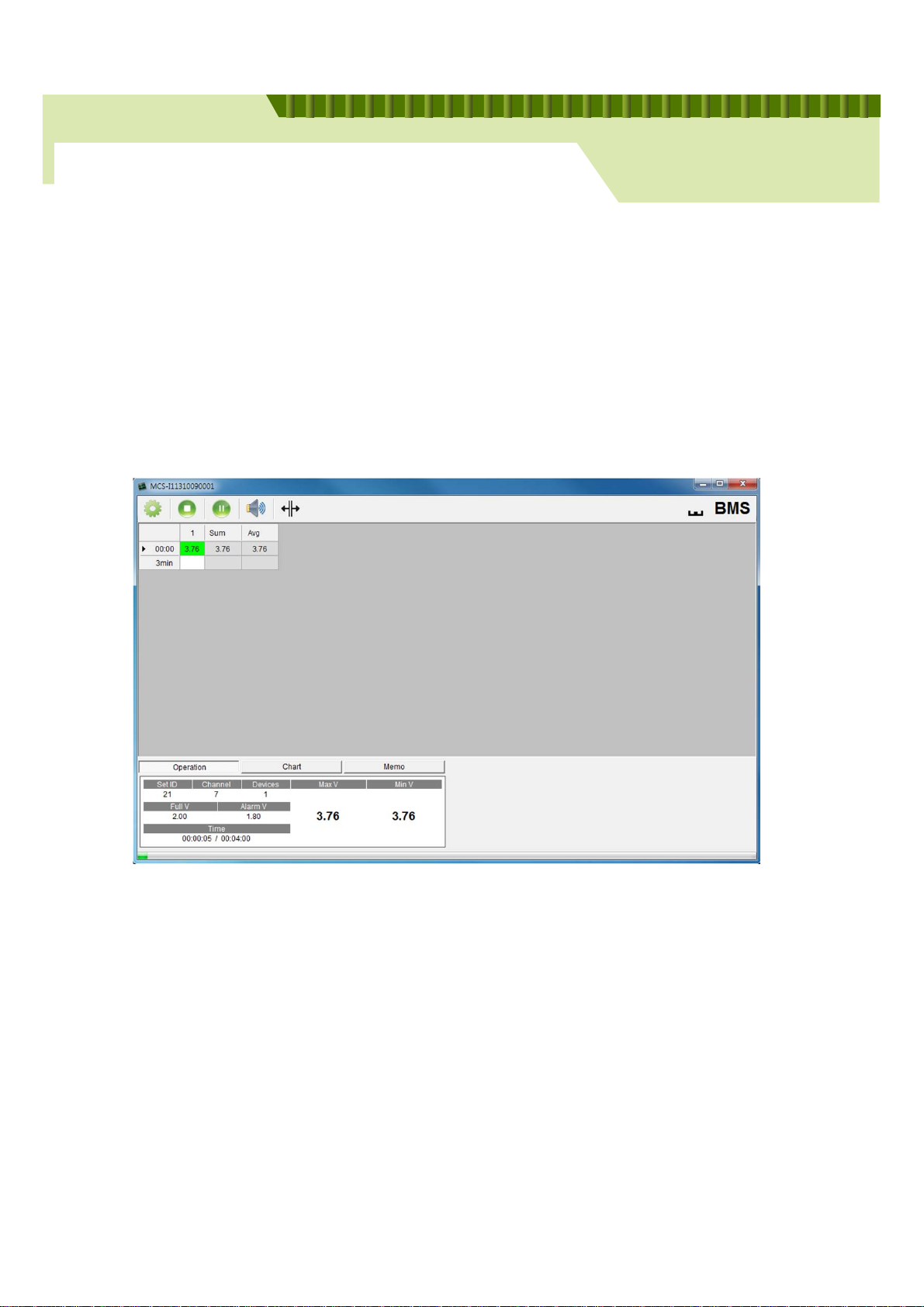
This is the screen of BMS operation. If it reaches of setting hour of press the stop
button, the monitoring program is finished and save the log-file.
www.maroomcs.com
Battery Regenerator
- the space is added every 3 minutes
- added space shows cell voltage.
- if the added space shows under set voltage, alarm rings.
17
Page 18
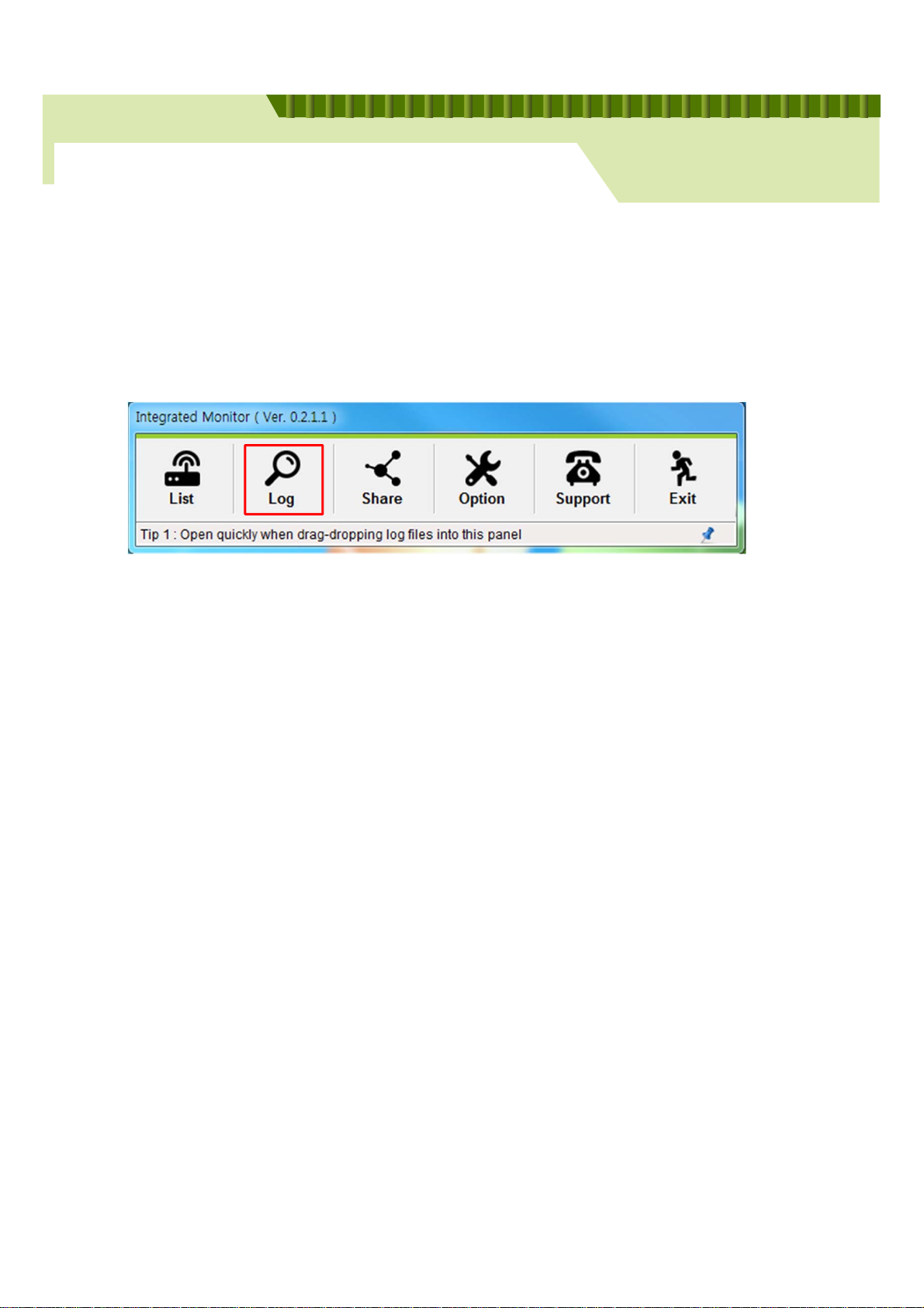
Chapter 2. PC Integrated Monitor Program
2-3 LOG
Open a Log File
www.maroomcs.com
Battery Regenerator
Log file show the details of existing operation in short time.
Issuing and printing Test Report for customer
Understand the history of MCS operation
18
Page 19
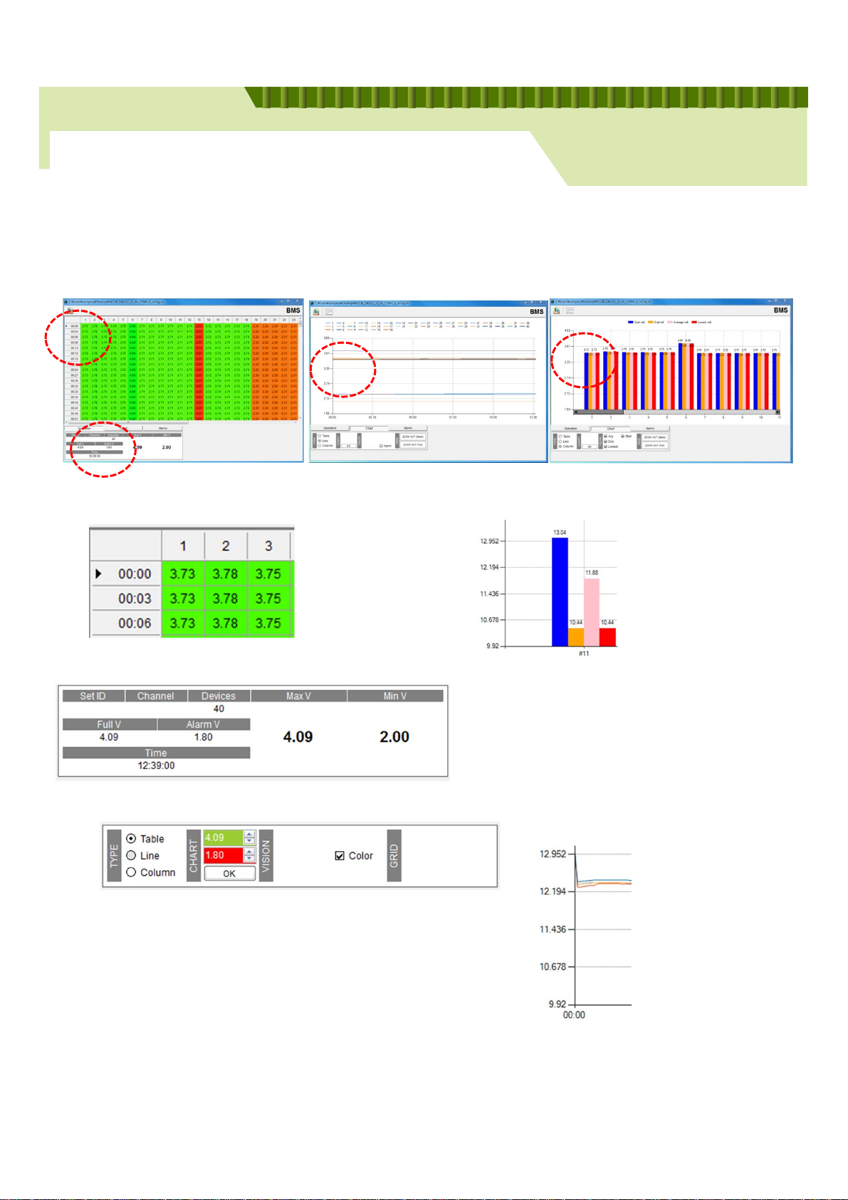
Chapter 2. PC Integrated Monitor Program
2-3 LOG
Analyzing chart
www.maroomcs.com
Battery Regenerator
Column – Cell number
Line – Operation time
Number - Voltage
Green - Good volt.
Red - Bad volt.
TYPE – Change the chart shape (table, line, stick)
CHART – Full Volt, Alarm Volt setting change
Y-axis - Voltage
Blue – start voltage
Orange – final voltage
Pink – average voltage
Red – minimum voltage
Time – total operation hour
Max V – maximum voltage during operation
Min V – minimum voltage during operation
Y-axis - Voltage
X-axis - Time
Color – color sign activated
19
Page 20
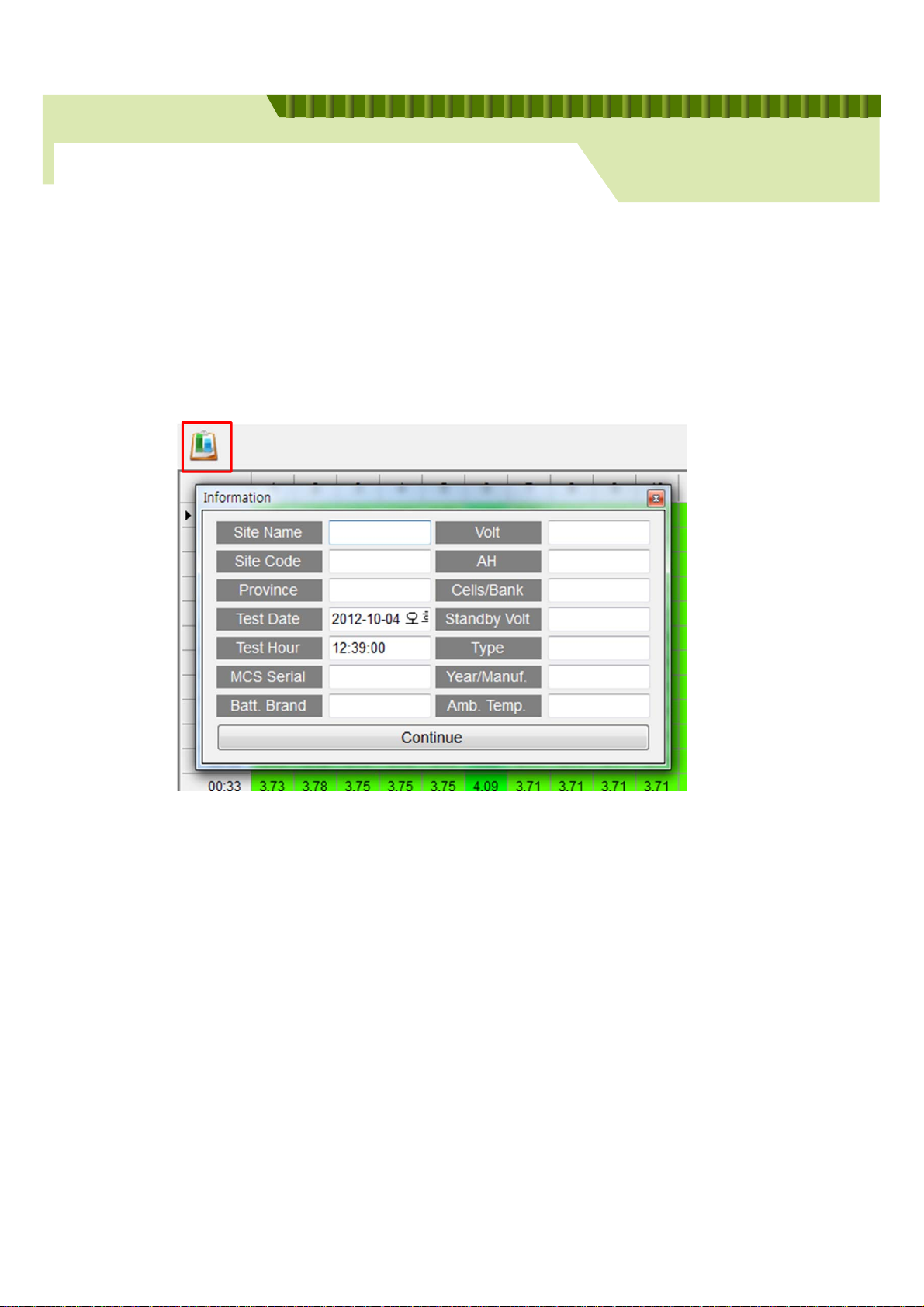
Chapter 2. PC Integrated Monitor Program
2-3 LOG
Print a log file
Click the left-top button for printing and fill in basic information.
www.maroomcs.com
Battery Regenerator
20
Page 21
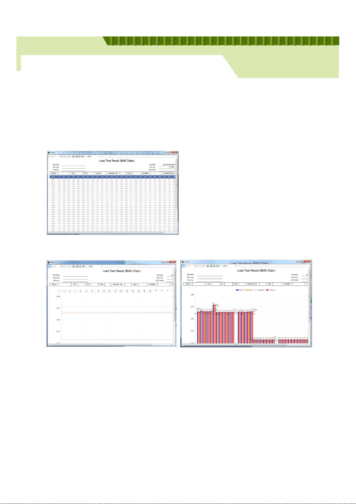
Chapter 2. PC Integrated Monitor Program
2-3 LOG
Print paper type
www.maroomcs.com
Battery Regenerator
• Table Cha r t
• Line Chart
• Table Cha r t
21
 Loading...