

Page 1

AC/DC True-RMSClamp Meter
Products Code: MCA-207
Instruction Manual
WWW.MARMONIX.CO
Page 2

CONTENTS
1. Measuring Limits
2. Safety Information
3. Features
4. Instrument Layout
5. Specifications
6. DC Current Measurement
7. AC Current Measurement
8. DC Voltage Measurement
9. AC Voltage Measurement
10. Resistance Measurement
11. Capacitance Measurement
12. Frequency Measurement
13. Temperature Measurement
14. Diode Test
15. Continuity Testing
16. Data Hold Functions
17. Peak Hold Functions
18. LCD Backlight
19. Auto Power Off
20. Battery Replacement
1. Measuring Limits
DC Amperes: 0.01A to 1000A
AC Amperes: 0.01A to 1000A
DC Voltage: 0.1mV to 600V
AC Voltage: 0.1mV to 600V
Page 3

Resistance: 0.1Ὠ to 40MὨ
Capacitance: 0.001 nFto 40mF
Frequency: 0.001 kHz to 4kHz
Temperature: -40˚C to 1000˚C
-40˚F to 1832˚F
2. Safety Information
This manual contains information that must be followed
for operating the meter safety and maintaining the
meter in a safe operating condition. If the meter is not
used in a manner specified in this manual, the protection
provided by the meter may be impaired.
The Model has been designed and complies with IEC
61010-1 and EN 61010-1 safety requirements for
Electronic Measuring Apparatus.
WARNING
Read through the operating instructions thoroughly
and understand the instructions before operating the
meter.
Keep the manual at hand so as to enable quick
reference when necessary.
Ensure that the use of the meter is in its intended
applications and follow measuring procedures
described in this manual.
Page 4

Follow all safety and operating instructions to ensure
maximum personal safety during the use and
operation of the meter.
Failure to follow the above instructions may cause
injury. Instrument damage and/or damage to
equipment under test.
The symbol indicated on the meter means that the
user must refer to related parts in the manual for safe
operation of the meter. Be sure to carefully read the
instructions following each symbol in this manual.
DANGER is reserved for conditions and actions that
are likely to cause serious or fatal injury
WARNING is reserved for conditions and actions that
are likely to cause serious or fatal injury.
CAUTION is reserved for conditions and actions that
are likely to cause minor injury
DANGER
Never use the meter to measure voltages on a circuit
above the maximum allowable input value on any
function.
Page 5

Do not exceed the maximum allowable input of any
measurement range.
Never touched exposed wiring, connections or any live
circuit when attempting to take measurement.
Do not attempt to make measurements in flammable
gaseous areas, fumes, vapor or dust. The use of the
instrument in these areas may cause sparking, which
can lead to an explosion.
Do not attempt to use the instrument if its surface or
your hand is wet.
Never open the battery compartment cover when
making measurements.
WARNING
Always inspect the meter and test leads for any signs of
damage or abnormality before use. If the meter or its
accessories have any structural defects such as broken
test leads, cracked cases, exposed metal parts or the
display is not reading, do not attempt to make
measurements.
Do not turn the function switch whilst test leads are
connected to the meter.
Do not install substitute parts or make modifications to
the meter. Return the meter to your distributor for
repair or re-calibration.
Page 6

Ensure the meter is switch off before opening the
battery cover when replacing the battery.
Never replace a battery if the surface of the meter is
wet or moist.
CAUTION
Before making measurements ensure that the function
selector switch is set on the appropriate range position.
Always make sure that the plug of each test lead is
inserted fully into the appropriate terminal of the
meter.
Ensure that the function selector switch is set to the
“OFF” position after use. When the meter will not be in
use for a long period of time, place it in storage after
removing the battery.
Do not expose the meter to direct sunlight, extreme
temperatures or moisture.
Do not abrasives or solvents on the meter. To clean it,
use a damp cloth and mild detergent only.
Qualified and trained service technicians should only
perform calibration and repair for the meter.
Page 7

3. FEATURES
True RMS measurement of AC Current ad AC Voltage
Large 4000 count LCD display with a bargraph and a
bright white LED backlight.
Wide measurement range from 0.01A AC/DC up to
1000A AC/DC
Measures AC and DC Voltage up to 600 volts
Measures resistance from 0.01Ὠ up to 40MὨ.
Capacitance measurements up to 40mF
Temperature measurements from -40˚C to +1000˚C and
-40˚F to +1832˚F.
Designed to the international safety standard IEC61010
CAT III 600V/ CAT II 1000V, Pollution degree 2.
Auto power off after approximately 20 minutes to
conserve battery life.
Continuity Buzzer and Diode Test
Frequency measurement up to 4kHz.
Peak Hold to record the minimum and maximum
readings for current and voltage.
Data Hold switch used to freeze readings on display.
Page 8

4. INSTRUMENT LAYOUT
Page 9

5. SPECIFICATIONS
Clamp Size 30mm Opening Approx
Diode Test Test Current of 0.3mA
typical; Open circuit voltage 1.5V DC
Continuity check Threshold<35Ὠ; Test
current<1mA
Low battery indication “ ” is displayed
Overrange Indication “OL” is displayed
Measurements Rate 2 per second, nominal
Input Impedance 10MὨ (VDC and VAC)
Display 4000 count LCD
AC Current 50/60Hz (AAC)
AC Voltage Bandwidth 50/60 (VAC)
Operating Temperature -10˚C to 50˚C (14˚F to
122˚F)
Storage Temperature -30˚C to 60˚C (-22˚F to
140˚F)
Relative Humidity UP to 85%
Over Voltage Category III 600V
Battery One DC 9V IEC6F22 1604
Battery
Auto Power Off Approx 20 minutes
Dimensions 229 x 80 x 49mm
Weight 303g
Page 10

5.SPECIFICATIONS
Range
Measuring Range
Resolution
Accuracy(% of Readings)
40A
0~40.00A
0.01A
±(2.8%+10digits)
400A
0~400.0A
0.1A
±(2.8%+8digits)
1000A
0~1000A
1A
±(3.0%+8digits)
Range
Measuring Range
Resolution
Accuracy(% of Readings)
40A
0~40.00A
0.01A
±(2.8%+10digits)
400A
0~400.0A
0.1A
±(2.8%+8digits)
1000A
0~1000A
1A
±(3.0%+8digits)
Range
Measuring Range
Resolution
Accuracy(% of Readings)
Range
Measuring Range
Resolution
Accuracy(% of Readings)
DC Current
AC Current
DC Voltage
400mV 0~400.0mV 0.1mV ±(0.8% + 2digits)
4V 0~4.00V 0.001V
±(1.5% + 2digits) 40V 0~40.00V 0.01V
400V 0~400V 0.1V
600V 0~600V 1V ±(2.0% + 2digits)
AC Voltage
400mV 0~400.0mV 0.1mV ±(0.8% + 2digits)
4V 0~4.00V 0.001V
±(1.5% + 2digits) 40V 0~40.00V 0.01V
400V 0~400V 0.1V
600V 0~600V 1V ±(2.0% + 2digits)
Note: No Autoranging on 400mV AC Range
Page 11

Resistance
Range
Measuring Range
Resolution
Accuracy(% of Readings)
Range
Measuring Range
Resolution
Accuracy(% of Readings)
Range
Measuring Range
Resolution
Accuracy(% of Readings)
400Ὠ 0~400.0 Ὠ 0. Ὠ ±(1.0% + 4 digits)
4k Ὠ 0~4.000k Ὠ 1 Ὠ
±(1.5% + 2 digits) 40k Ὠ 0~40.00k Ὠ 10 Ὠ
400kV 0~400.0k Ὠ 100 Ὠ
4M Ὠ 0~4.000M Ὠ 1k Ὠ ±(2.5% + 5digits)
40M Ὠ 0~40.00M Ὠ 10k Ὠ ±(3.5% + 10 digits)
Capacitance
4nF 0~4.000nF 0.001nF ±(5.0% + 30 digits)
40nF 0~40.00nF 0.01nF ±(5.0% + 20 digits)
400nF 0~400.0nF 0.1nF
±(3.0% + 5 digits) 4μF 0~4.000μF 0.001μF
40μF 0~40.00μF 0.01μF
400μF 0~400.0μF 0.1μF ±(4.0% + 10 digits)
4mF 0~4.000mF 0.001mF ±(4.5% + 10 digits)
40mF 0~40.00mF 0.01mF ±(5.0% + 10 digits)
Frequency
4kHz 0~4.000kHz
0.00kHz
±(1.5% + 2 digits)
Sensitivity: 5Vrms min
Page 12

Temperature
Accuracy(% of Readings)
Range Measuring Range Resolution
˚C -40˚C~1000˚C 1˚C ±(2.5˚% + 3˚C)
˚F -40.0˚F~1832˚F 1˚F ±(2.5% + 5˚F)
6. DC Current Measurement
WARNING: Ensure that the test leads are
disconnected from the meter before making
current measurements.
1. Set the function switch to 1000A or 400A or 40A
range position, and make sure that the current
under test does not exceed the upper limit of the
measuring range you have selected. The meter
automatically defaults to DC Current.
2. Press the DC ZERO button once, the sign will
appear on the LCD indicating Range is zero.
3. Press the trigger to open up the transformer jaws
and clamp around the single conductor under
test.
4. Read the display.
Note:
During current measurements keep the
transformer jaws fully closed, otherwise
this will affect the accuracy of the
measurement.
Page 13

When large currents the transformers jaws
may buzz. This is not a fault and does not
affect the accuracy of the reading.
Page 14

7. AC True RMS Current Measurement
WARNING: Ensure that the test leads
are disconnected from the meter
before making current measurements.
1. Set the function switch to 1000A~ or 400A~ or
40A~range position, and make sure that the current
under test does not exceed the upper limit of the
measuring range you have selected.
2. Press the MODE button to select the AC Current range.
The meter automatically defaults to Dc Current.
3. Press the trigger to open up the transformer jaws and
clamp around the single conductor under test.
4. Read the display.
Note:
During current measurements keep the transformer
jaws fully closed, otherwise this will affect the accuracy
of the measurement.
When large currents the transformer jaws may buzz.
This is not a fault and does not affect the accuracy of
the reading.
The meter is set to default to “Auto Range” mode.
Pressing the PEAK hold button will allow the user to
record the peak maximum and minimum readings on
the AC volt range. See page 17 for further instructions
for “PEAK” Hold function.
Page 15

Page 16

8. DC Voltage Measurement
1. Set the function switch to range position. The
meter automatically defaults to DC Volts.
2. Insert the test lead into the “V Ὠ TEMP HZ” input
terminal and the black lead to the “COM” terminal.
3. Connect the other end of the test leads to the circuit
under test.
4. Read the display. If a “-“ sign is displayed, the red leads is
the negative potential.
Page 17
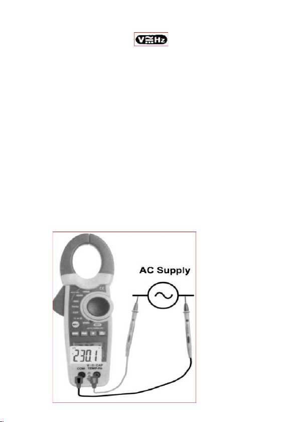
9. AC true RMS voltage measurement
1. Set the function switch range position.
2. Press the MODE button to select the AC Volt range. The
meter automatically defaults to DC Volts.
3. Insert the red test lead into the “V Ὠ TEMP HZ” input
terminal and the black lead to the “COM” terminal.
4. Connect the other end of the test leads to the circuit
under test. Take the reading on the display.
Note:
The meter is set to default to “Auto Range” mode.
Pressing the PEAK hold button will allow the user to
record the peak maximum and minimum readings on
the AC volt range. See page 7 for further instructions for
“PEAK” Hold function.
Page 18

10. Resistance Measurement
1. Set the function switch to range position.
The meter automatically defaults to resistance
range.
2. Insert the test lead into the “V Ὠ TEMP HZ” input
terminal and the black lead to the “COM” terminal.
3. Connect the other end of the test leads to the circuit
or component under test. Take the reading on the
display.
Note:
The meter is set to default to “Auto Range” mode.
WARNING before attempting to make a
resistance measurement, ensure there is no voltage
present on the circuit under test.
Page 19

11. Capacitance Measurement
1. Set the function switch to CAP range position.
2. Insert the test lead into the “V Ὠ TEMP HZ” input
terminal and the black lead to the “COM” terminal.
3. Connect the other end of the test leads to the circuit or
component under test. Take the readings on the
display.
Note:
In capacitance range the meter is Auto Ranging only.
CAUTION to avoid damage to the meter or the
equipment under test, remove all power from the
circuit and discharge all capacitors before measuring
capacitance.
Large value capacitors should be discharged through
an appropriate resistance load. Use the DC Voltage
function to confirm that the capacitors are discharged.
Page 20

12. Frequency Measurement
1. Set the unction switch to range position. The
meter automatically defaults to Frequency range.
2. Press the MODE button for 3 seconds to select the
Frequency range. The meter automatically defaults
to DC Voltage.
3. Insert the test lead into the “V Ὠ TEMP HZ”input
terminal and the black lead to the “COM” terminal.
4. Connect the other end of the test leads to the circuit
or component under test. Take the readings on the
display.
Note:
In the Frequency Range the meter is Auto Ranging
only.
Page 21
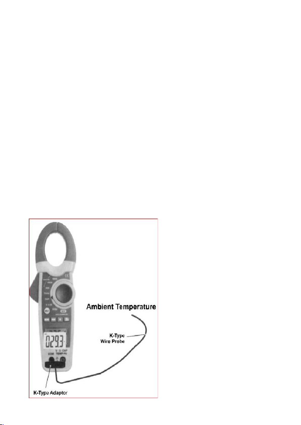
13. Temperature Measurement
1. Set the functions switch to TEMP range position. The meter
automatically defaults to ˚C range.
2. Insert the meter white temperature adaptor into the “V Ὠ
TEMP HZ” input terminal and the “COM” terminal. Ensure
that the “-“ marking on the adaptor is inserted into the
“COM” terminal and the “+” marking on the adaptor is
inserted into the “V Ὠ TEMP HZ” input terminal.
3. Connect any K-Type probe into the meter adaptor and
measure the temperature of the apparatus or area required.
4. Read the temperature directly on the display.
5. To change the measuring unit from ˚C to ˚F, press the MODE
button to select the ˚F unit.
Note:
The meter is set to default to “Auto Range” mode.
Page 22

14. Diode Test
1. Set the function switch to range position.
2. Press the MODE button to select the Diode Test range.
The meter automatically defaults to resistance.
3. Insert the red test lead into the “V Ὠ TEMP HZ” input
terminal and the black lead to the “COM” terminal.
4. Connect the other end of the test leads to the
components under test. Read the display.
Note:
Use the diode test to check diodes, Transistors, silicon
controlled rectifiers (SCR’s) and other semiconductor
devices.
The test sends a current through a semiconductor
junction, then measures the junction’s voltage drop.
Normal forward voltage drop (forward bias) for a good
silicon diode is between 0.4V to 0.9V. a reading higher
than that indicates a leaky (defective) diode. A zero
reading indicates a shorted diode.
Reverse the test leads connection (reverse bias) across the
diode. The display shows “OL” if the diode is good. Any other
readings indicate the diode is shorted or resistive
(defective).
Page 23

15. Continuity Testing
1. Set the function switch to range position.
2. Press the MODE button to select the Continuity Test
range. The meter automatically defaults to Resistance.
3. Insert the red test lead into the “V Ὠ TEMP HZ”input
terminal and the black lead to the “COM” terminal.
4. Short the tip of the test leads and makes sure the
display reads “0” and the buzzer beeps.
5. Connect the tip of the test leads to the circuit or
component under test. The display reads the
resistance and the buzzer beeps when the reading is
not more than about 35Ὠ.
Note:
Using resistance and continuity function in a live circuit
will produce false results and may damage the
instrument.
In many cases the suspicious components must be
disconnected from the circuit under test to obtain
accurate results.
WARNING before attempting to make a test, ensure
there is no voltage present on the circuit.
Page 24

Page 25

16. DATAHOLD
This is a function used to freeze the reading on the
display, ideal for later viewing.
1. Press the HOLD button once. When the HOLD is
activated, the meter beeps, freezes the reading, and
displays the “HOLD” indicator on the LCD.
2. To deactivate the “HOLD” function, press HOLD
button once, the meter will beep and the meter will
start reading new measurements.
17. PEAK HOLD
This is a function used to record the maximum and
minimum readings on the display for the voltage and
current ranges.
1. Press the PEAK button once. This will record the
PEAK maximum, the meter beeps, and displays the
“P MAX” indicator on the LCD.
2. Press the PEEK button again. This will record the
“PEAK” minimum, the meter beeps, and displays the
“P MIN” indicator on the LCD.
3. To deactivate the “PEEK” function, press button for 3
seconds, the meter will beep and the meter will start
reading new measurements.
18. LCD Backlight
The backlight is ideally used in dark or dimly lit areas.
1. Press the button for 3 seconds, and the bright
white light will come on.
Page 26

2. To turn off the backlight press the button for 3
seconds.
Note: the use of the backlight will reduce the battery
life considerably.
19. Auto Power Off
This feature automatically turns off the meter after
approximately 20 minutes from the last measurement
taken. To turn on the meter, press any button or move
the rotary switch to any position. Ensure the test leads
are disconnected from any circuit to avoid injury or
meter damage.
20. Battery Replacement
When the sign appears on the LCD, this indicates
the battery should be replaced. Use the following
procedure to replace the standard 9V battery (IEC 6F
22) battery.
1. Disconnect the test leads from any live source and
remove the leads from the input terminals.
2. Rotate the function switch to the OFF position.
3. The battery cover is secured to the bottom of the
case by a screw. Using a screwdriver remove the
screw from the battery cover and remove the
battery cover from the meter.
4. Remove the old battery and replace it with a new
IEC 6F 22 9V battery.
Page 27

5. Replace the battery cover and reinstall the screw.
 Loading...