

Page 1
20036 / 220403 COPYRIGHT MARMITEK 2003 - ALL RIGHTS RESERVED
MODE D’EMPLOI 41
BETRIEBSANLEITUNG 21
USER’S MANUAL 2
GEBRUIKSAANWIJZING 57
WJ1512/WJ1512Q
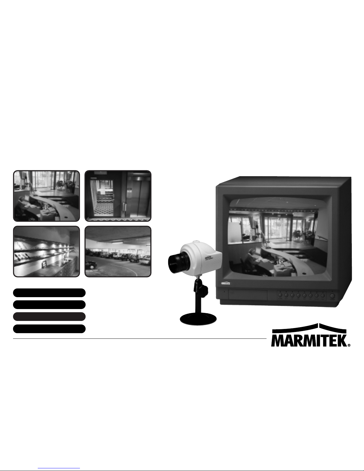
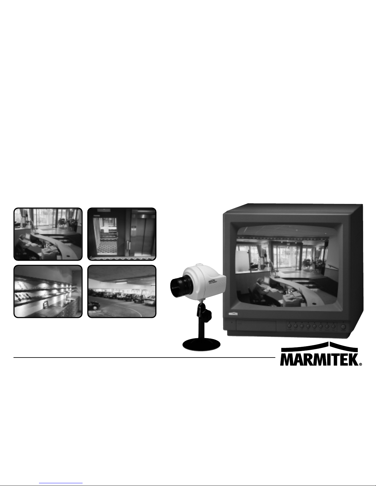
VIDEO SURVEILLANCE SYSTEM • VIDEOÜBERWACHUNGSSYSTEM • SYSTÈME DE VIDÉO SURVEILLANCE • VIDEO-OBSERVATIESYSYTEEM
Page 2
2 MARMITEK
RISK OF ELECTRIC SHOCK
DO NOT OPEN.
CAUTION
WARNING
CAUTION
WARNING
TO REDUCE THE RISK OF FIRE OR ELECTRIC SHOCK HAZARD, DO NOT EXPOSE THIS APPLIANCE TO RAIN
OR MOISTURE.
DO NOT INSERT ANY METALLIC OBJECT THROUGH VENTILATION GRILLS.
Explanation of Graphical Symbols
This symbol is intended to alert the user the presence of uninsulated, dangerous voltage within the product's
enclosure that may be of sufficient magnitude to constitute a risk of electric shock.
This symbol is intended to alert the user to the presence of important operating and
maintenance instructions in the literature accompanying the appliance.
CAUTION : TO REDUCE THE RISK OF ELECTRIC SHOCK DO
NOT REMOVE COVER (OR BACK) NO USER SERVICEABLE
PARTS INSIDE FOR SERVICING REFER TO QUALIFIED
SERVICE PROFESSIONAL
Page 3

31512/1512Q
ENGLISH
IMPORTANT SAFEGUARDS
1. READ INSTRUCTIONS-All the safety and operating instructions should
be read before the appliance is operated.
2. RETAIN INSTRUCTIONS-The safety and operating instructions should
be retained for future reference.
3. CLEANING-Unplug this television from the wall outlet before cleaning.
Do not use liquid cleaners or aerosol cleaners. Use a damp cloth for
cleaning.
4. ATTACHMENTS-Do not use attachments not recommended by the
television equipment manufacturer as they may result in the risk of fire,
electric shock or injury to persons.
5. WATER AND MOISTURE-Do not use this television equipment near
water-for example, near a bathtub,washbowl, kitchen sink, laundry tub,
in a wet basement, near a swimming poll, or the like.
6. ACCESSORIES-Do not place this television equipment on an unstable
cart, stand or table. The television equipment may fall, causing serious
injury to a child or adult, and serious damage to the equipment. Wall or
shell mounting should follow the manufacturer's instructions, and should
use a mounting kit approved by the manufacturer.
6A. Television equipment and cart combinations should be moved with care.
Quick stops, excessive force, and uneven surfaces may cause the
equipment and cart combination to overturn.
7. VENTILATION-Slots and openings in the cabinet and the back or bottom
are provided for ventilation, and to ensure reliable operation of the
television equipment and to protect it from overheating. These openings
must not be blocked or covered. The openings should never be blocked by
placing the television equipment on a bed,sofa, rug. or other similar
surface. This television equipment should never be placed near or over
a radiator or heal register. This television equipment receiver should not be
placed in a built-in installation such as a bookcase unless proper ventilation
is provided.
8. POWER SOURCES-This television equipment should be operated only
from the type of power source indicated on the marking label. If you are not
sure of the type of power supplied to your home. consult your television
dealer of local power company. For television equipment designed to
operate from battery power refer to the operating instructions.
9. GROUNDING OR POLARIZATION-This television equipment is provided
with a polarized alternating-current line plug(a plug having one blade wider
then the other). The plug will fit into the power outlet only one way. This is a
safety feature. If you, are unable to Insert the plug fully into the outlet, try
reversing the plug. If the plug should still fail to fit, contact your electrician to
replace your obsolete outlet. Do not defeat the safety purpose of the
polarized plug.
Page 4

4 MARMITEK
IMPORTANT SAFEGUARDS
10. POWER CORDS-Do not allow anything to rest on the power cord.
11. HEED WARNINGS-Follow all instructions marked on the television
equipment.
12. LIGHTNING-For added protection for this television equipment during
a lighting storm, or when it is left unattended and unused for long
periods of time, unplug it from the wall outlet and disconnect the
antenna or cable system. This will prevent damage to the video
product due to lightning and power-line surges.
13. OVERLOADING-Do not overload wall outlets and extension cords as
this can result in a risk of fire or electric shock.
14. OBJECT AND LIQUID ENTRY-Never push objects of any kind into
television equipment through openings as they maying touch
dangerous voltage points or short-out parts that could result in a fire or
electric shock. Never spill liquid of any kind on the product.
15. SERVICING-Do not attempt to service this television equipment
yourself as opening or removing covers may expose you to
dangerous voltage or other hazards. Refer all servicing to qualified
service personnel.
16. DAMAGE REQUIRING SERVICE-Unplug this television equipment
from the wall outlet and refer servicing to qualified service personnel
under the following conditions:
A. When the power supply cord or the plug has been damaged.
B. If liquid has been spilled,or objects have fallen into the video
product.
C. If the video product has been exposed to rain or water.
D. If the video product does not operate normally by following the
operating instructions, adjust only those controls that are covered
by the operating instructions as an improper adjustment of other
controls. may result in damage and will often require extensive
work by a qualified technician to restore the video product to its
normal operation.
E. If the video product has been dropped, or the cabinet damaged.
F. When the video product exhibits a distinct change in performance -
this indicates a need for service.
17. REPLACEMENT PARTS-When replacement parts are required, be
sure the service technician has used replacement parts specified by
the manufacturer or that have the same characteristics as the
original part. Unauthorized substitutions may result in fire, electric
shock or other hazards.
18. SAFETY CHECK-Upon completion of any service or repairs to this
video product, ask the service technician to perform safety checks to
determine that the video product is in proper operating condition.
SAVE THESE INSTRUCTIONS.
Page 5

51512/1512Q
ENGLISH
TABLE OF CONTENTS
Introduction ............................................................................................. 6
Features .................................................................................................. 6
Precaution Before Installing or Using the System ................................... 6
Description of Controls
Monitor Unit .....................................................................................7-10
Camera Unit .......................................................................................11
Installation
Camera Unit ......................................................................................12
Monitor Unit .................................................................................. 13-14
Wiring Diagram ..................................................................................... 15
Trouble shooting guide ......................................................................... 16
Specifications
Monitor Unit ....................................................................................... 17
Camera Unit ...................................................................................... 18
Accessories ...........................................................................................19
Care and Maintenance .......................................................................... 20
page
Page 6

6 MARMITEK
This OBSERVATION SYSTEM will give you added security and comfort for many years. It is easy to install in almost
anywhere you need audio/video surveillance. To safety use all the high technical functions of the unit, please read the
installation and operating instruction in manual, and keep it for future reference.
FEATURES
Highly reliable circuit to assure best quality picture.
Availability of up to 4 camera connections.
Easy to install and operate.
Compact, lightweight and versatile.
High resolution monitor
Low, minimum lighting requirement.
Manual or auto camera selector switch.
3 to 60 seconds auto camera switching speed adjustable.
2 way audio monitoring
VCR Recordable
Alarm function
Slave monitor output
Wide range of accessories
Main / Stand by monitor power switches
DIN connector as well as BNC connector
Read the following precautions before installing or using the system
1. Choose an ideal location for the camera so that the lens won't be exposed to any direct light source.
The camera unit must also be protected against moisture and vibration.
2. The monitor should only be operated with the correct power source indicated on the specification.
3. Check the system for operation prior to installing the unit.
4. Be extra careful not to scratch the camera lens.
INTRODUCTION
Page 7
71512/1512Q
ENGLISH
DESCRIPTION OF CONTROLS & OPERATION
VCR
OFFON
6 1 2 3
4
5
8
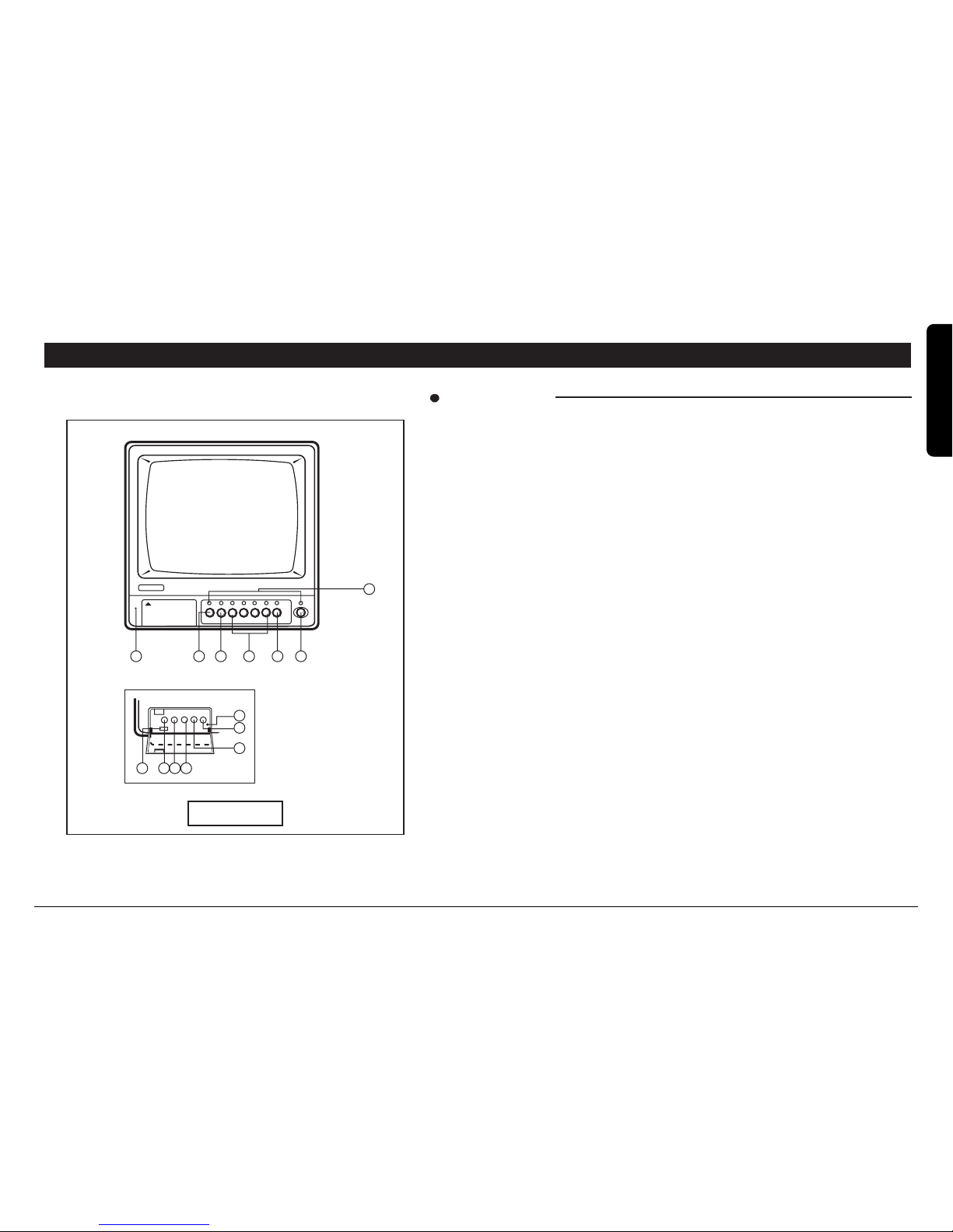
FRONT VIEW
Front View
1. TIME CONTROL KNOB
To vary the display switching speed from 3 to 60 seconds. When the system is
in the auto mode with more than one camera, this knob enables you to vary
the time of stay from one location to another from 3 to 60 seconds. Turning this
knob in clockwise direction will increase the time of stay up to 60 seconds.
Turning this knob all the way in counter clockwise direction will quickly show
the locations.
2. BRIGHTNESS CONTROL KNOB
To adjust the BRIGHTNESS of the screen.
3. CONTRAST CONTROL KNOB
To adjust the CONTRAST of the screen.
4. VERTICAL HOLD CONTROL KNOB
To adjust the VERTICAL synchronization.
5. VOLUME CONTROL KNOB
Turn on the volume control up or down to reach volume desired.
6. VCR ON/OFF SELECTOR
Press it to review the video signal from VCR. Press it again to stop the video
signal. VCR Recording Reviewing Method
1) Connect the monitor to the VCR and press the RECORD button on the
VCR to start recording the pictures.
2) To review the recorded pictures, press the VCR button on the monitor and
then the PLAY button on the VCR.
7. MICROPHONE
Pick up sound around the monitor.
A. MONITOR
QUADAUTO CA1 CA2 CA3 CA4 TALK
POWER
7 9 10 11 12 13
14
PUSH
Page 8

8 MARMITEK
DESCRIPTION OF CONTROLS & OPERATION
8. ALARM ON/OFF SELECTOR
Switches alarm function on/off. NB alarm function is set to on position
upon activation of the monitor via power switch
DESCRIPTION OF THE ALARM FUNCTION
The alarm function is designed to automatically control picture
selection upon receipt of signals from alarm devices such as PIRS,
contacts or panic buttons, alert the operator and even trigger
additional equipment such as a time lapse VCR. Each camera
channel has an associated alarm trigger input. Irrespective of the
camera switching mode (ie Manual or Auto) the system will instantly
switch to the channel on which an alarm trigger has been received
and emit a warning sound for 15 secs. After this period allowing that
no further alarm triggers are received the system will automatically
revert to the mode in which it was originally set. Should additional
triggers be received during the 15 second period the system will
automatically switch to the relevant cameras and continue the
warning sound. At the time of trigger the system can also send an
output to external equipment such as a time lapse VCR in event
record mode or through an additional relay to lighting or alarm sound
etc. The alarm trigger device should be normally open. The alarm
output can be either normally open or normally closed.
10. PROGRAMMABLE AUTO SEQUENCE
Turns on/off the Auto Sequence Mode. In auto mode the system will
picture of any camera on the Monitor, press desired camera button
and if you want to see quad mode, press quad button. When turning
the system on, the monitor display quadrant picture.
9. QUAD SWITCH (only on model 1512Q)
Displays up to four cameras on the screen at one time. The pictures
are reduced in size to one-fourth of the screen of the screen. The
screen is divided into four quadrants. If you want to see full screen
switch between preset channels at a time sequence set by the dwell
time adjuster. The sequencer is also programmable. Press and hold
the auto button for 3 seconds, this will enable sequence memory
mode and cause the auto LED to flash. With the auto led flashing
press the channel of each camera required to be included in the
display sequence (in the order that you wish them to be displayed).
When your selections are finished press the auto button in order to
lock the memory.
IMPORTANT-This operation must be carried out when using
less than 4 cameras in order to avoid switching to a blank
screen.
NB: The memory will be lost if the power to the monitor is lost.
11.
CAMERA-1,2,3,4 BUTTONS
Press each button to monitor the desired channel.
12.
TALK
Press and hold this button to communicate through selected camera
channel. Release to hear sound from selected camera channel.
13.
POWER ON/OFF SWITCH (STAND BY)
By pushing the stand-by button the image and sound on the monitor
can be switched ON and OFF. The alarm functions also remain
active.
14.
LED INDICATORS
LED, POWER, ALARM, AUTO, CAMERA 1~4, TALK function indicators.
(‘Quad’ only on model 1512Q)
IN Alarm input (normally open)
GND
Ground
B+
Power output +12V DC 100mA
Page 9
91512/1512Q
ENGLISH
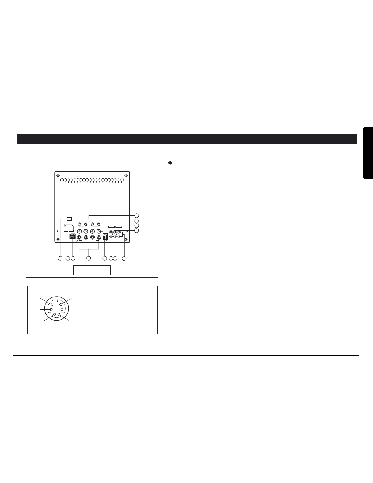
REAR VIEW
15. MAIN POWER SWITCH
This switch is used to turn ON or OFF all power to the monitor.
16. AC POWER CORD
Plug the AC power supply cord.
17. ALARM FUNCTION INPUT / OUTPUTS
Switch alarm function on/off NB alarm function is set to on position upon
activation of the monitor via power switch.
18. VIDEO INPUT
Receives video signal from VCR or another video unit.
19. VIDEO OUTPUT
Transmits video signal from a camera to another monitor.
Also used in recording on VCR.
20. AUDIO INPUT
Receives audio signal from VCR or audio amplifier.
21. AUDIO OUTPUT
Transmits audio signal to audio amplifier. Also used in recording on VCR.
Rear View
DESCRIPTION OF CONTROLS & OPERATION
A)B+
B)Audio in
C)Camera audio AMP:B+
D)Video in
E)Audio out
F)N.C
D
E
F
A
B
C
23 1826 19
22
20
21
24
25
15 16 17
POWER
AC IN PUT
ALARM OUT
COM
NC
N.O
CAMERA IN PUT
V C R
IN OUT OUT
AUDIO
VIDEO
SLAVE
1234
VIDEO IN
1234
AUDIO IN
CA1 CA2 CA3 CA4
REMOTE
Page 10

10 MARMITEK
22. SLAVE MONITOR OUTPUT
Audio and video output for slave monitor. Connect via double male to
double male phone leads of required length. NB: Maximum
recommended distance between master and slave monitor is 20m.
23. CAMERA INPUT JACKS.
Connect to 4 cameras.
24. AUDIO INPUT
These inputs are looping used for Audio.
25. BNC CAMERA INPUTS 1~4
These inputs are used for standard cameras with BNC type
connectors.
26. REMOCON
Connect to wire remote control (optional). The controls all of the
switcher functions on the front panel of the monitor.
DESCRIPTION OF CONTROLS & OPERATION
Page 11
111512/1512Q
ENGLISH
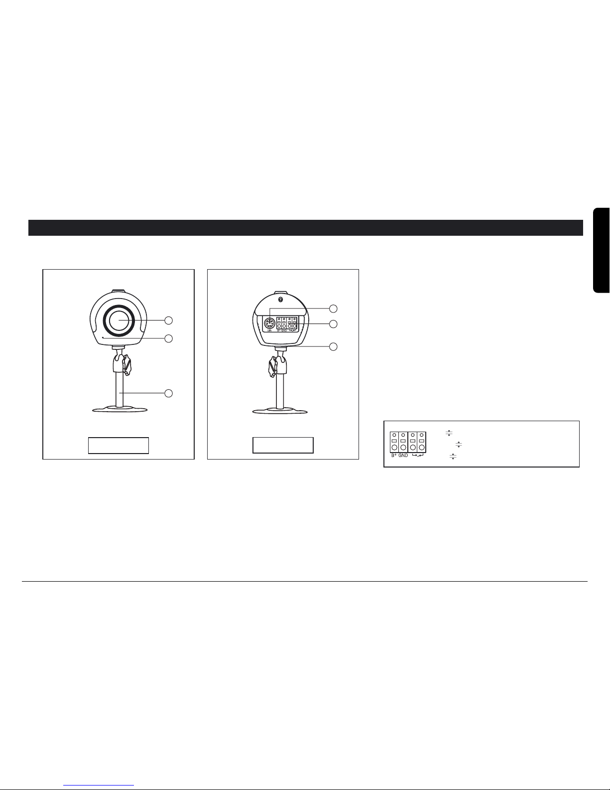
1. CCD CAMERA LENS
Turn the front ring of the lens to obtain the focus
desired.
2. MICROPHONE
Pick up sound around the camera.
3.MONITOR INPUT JACK
Connect to cable the monitor.
4.
ALARM TERMINAL
Connect an optional alarm device to this
terminal.
5.
SPEAKER
Deliver the sound from the monitor.
6. BRACKET
DESCRIPTION OF CONTROLS & OPERATION
B. Camera Unit
Front View
Rear View
1
2
6
3
5
4
IN Alarm input (normally open)
GND
Ground
B+
Power output +12V DC 100mA
Page 12
12 MARMITEK
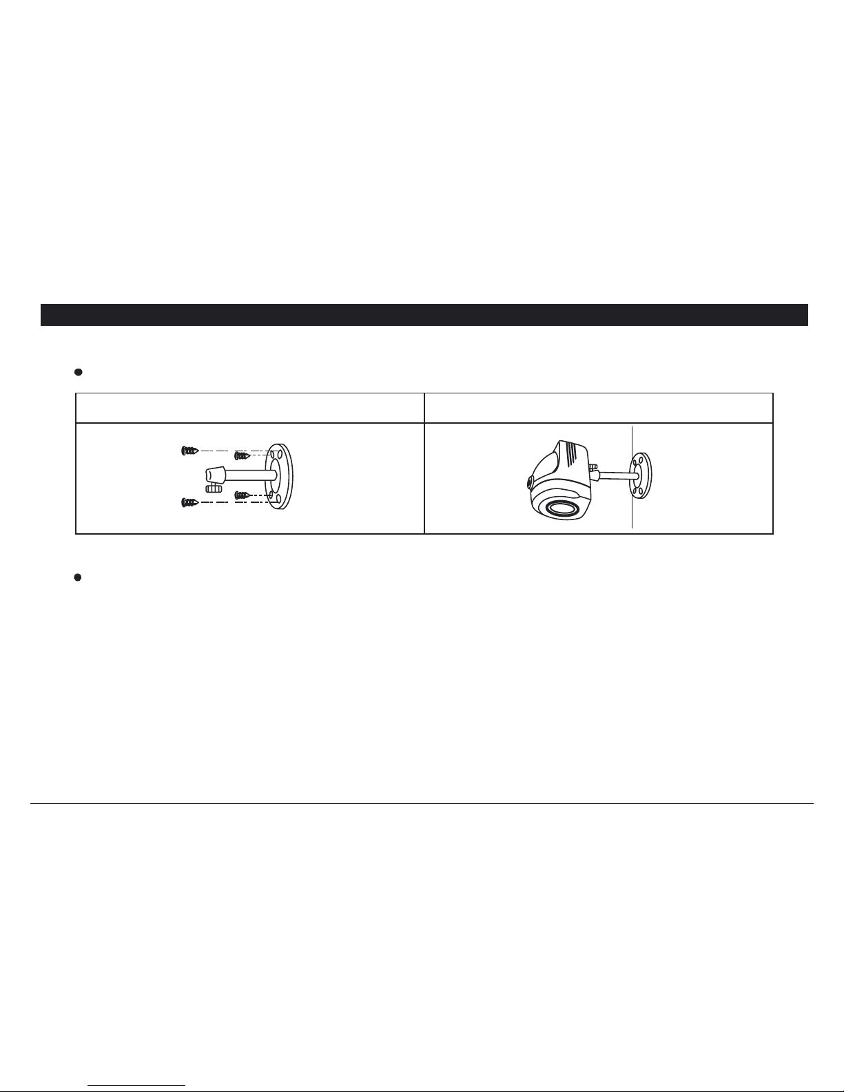
INSTALLATION
A. Camera Unit
Permanent installation using pedestal stand.
CAUTION : Keep camera installed away from direct sunlight. Also avoid places where humidity is high or where
the camera is not protected from rain.The mounting bracket must be attached to a structural object such
as a wall stud or ceiling rafter using suitable fastener. Do not touch the glass of the lens. This could
damage the delicate coating on its surface. If the lens has to be cleaned, use a special lens cleaning
tissue available at any good camera store.
1. Attach the Pedestal using 4 screws.
2. Attach the Camera onto the Pedestal and tighten
the thumb screw.
Page 13
131512/1512Q
ENGLISH
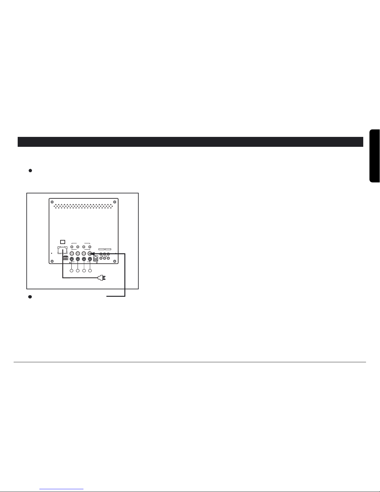
INSTALLATION
1. Camera 1 Terminal
Connect camera 1 cable to this terminal.
2. Camera 2 Terminal
Connect camera 2 cable to this terminal.
3. Camera 3 Terminal
Connect camera 3 cable to this terminal.
4. Camera 4 Terminal
Connect camera 4 cable to this terminal.
POWER
AC IN PUT
ALARM OUT
COM
NC
N.O
CAMERA IN PUT
V C R
IN OUT OUT
AUDIO
VIDEO
SLAVE
1234
VIDEO IN
1234
AUDIO IN
CA1 CA2 CA3 CA4
REMOTE
1 2 3 4
AC power cord
1-4 Camera connections
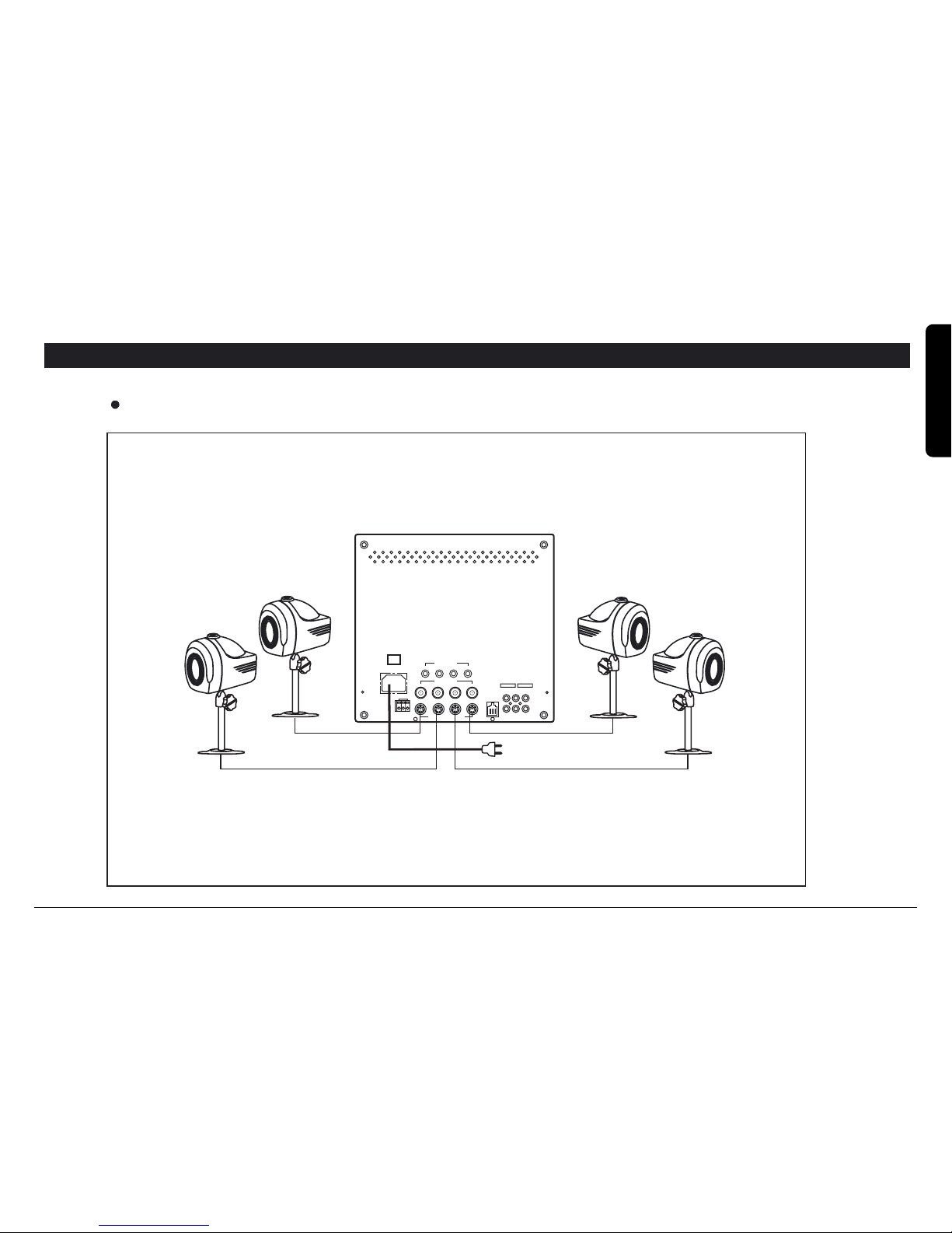
Using the provided cables, connect the camera to the monitor as shown in the diagram below.
Monitor with BNC cameras
The observation monitor may be installed with a standard BNC output security camera. Connect one end of the BNC
video cable to the output of the camera and the other end of the BNC video cable to the BNC camera input on the
rear of the observation monitor.
NOTE : Do not plug an observation camera and a BNC camera into a same camera port on the rear of the observation
monitor.
Example) Observation camera 1 (CA 1) - CA 1 port DIN terminal
BNC camera 1 (CA 1) - CA 1 port BNC input (jack)
B. Monitor Unit
Page 14

14 MARMITEK
INSTALLATION
AUDIO/ VIDEO JACK CONNECTIONS.
Refer to the following connection method, when connecting to the VCR
INSTALLATION WITH A TIME- LAPSE RECORDER.
Monitor VCR Terminal
Video OUT Video IN
Audio OUT Audio IN
Video IN Video OUT
Audio IN Audio OUT
Monitor Back view TIME lapse recorder
Video 1 OUT Video IN
Audio 1 OUT Audio IN
Video IN Video OUT
Audio IN Audio OUT
SLAVE Monitor
Video 2 OUT Video IN
Audio 2 OUT Audio IN
NOTE: The cable for this connection is not supplied with the unit.
Page 15
151512/1512Q
ENGLISH
NOTE: Do not use RCA jack to connect any cameras.
WIRING DIAGRAMS
WIRING Connections
CAMERA 1
CAMERA 4
MONITOR
CAMERA 2
CAMERA 3
POWER
AC IN PUT
ALARM OUT
COM
NC
N.O
CAMERA IN PUT
1234
VIDEO IN
1234
AUDIO IN
CA1 CA2 CA3 CA4
V C R
IN OUT OUT
AUDIO
VIDEO
SLAVE
REMOTE
Page 16

16 MARMITEK
Monitor
Problem
Multiple image in picture
Picture rolls up or down
Too dark or bright picture.
NO POWER
Poor picture quality
Picture but no sound
Sound but no picture
Shrinking picture
Check Point
Readjust the VERTICAL Hold
control knob.
Readjust the VERTICAL Hold
control knob.
Readjust the CONTRAST or
BRIGHTNESS controls.
Check for AC connection.
Clean the camera lens.
Readjust the CONTRAST or
BRIGHTNESS controls.
Adjust the VOLUME control
knob.
Readjust the CONTRAST
or BRIGHTNESS controls.
Check the condition of the
POWER source.
Before calling service, check the following points for possible misuse.
TROUBLE SHOOTING GUIDE
Page 17

171512/1512Q
ENGLISH
TECHNICAL SPECIFICATIONS
12 cm B/W
1.0V p-p
75 ohm
1V p-p
Over 800 TV lines
1V p-p, 75 , 4 BNC connector, 4 DIN connector
1V p-p, 75 , 4 RCA connector
0.5W
3 PIN push terminals (NO, NC, COM)
Off / 15 Seconds
RCA connector
RCA connector
RCA connector
RCA connector
RCA connector
8 PIN modular jack
100-240V~, 50/60Hz, 0.8A
-10 C ~ +50 C
315(W) X 330(D) X 305(H)mm
Metal with plastic front
9.0 Kg
Monitor
Picture tube
Video input level
Video input impedance
Video output level
Resolution
Video inputs
Audio input
Speaker
Alarm output
Alarm time
VCR Video input
Audio input
Video output
Audio output
Slave A/V monitor output
Remocon connector
Electrical rating
Operating temperature
Dimensions
Cabinet
Weight
Page 18

18 MARMITEK
TECHNICAL SPECIFICATIONS
Camera
Image sensor
Effective picture elements
Camera power input
Video output
Built-in microphone
Speaker
Microphone
System connection
Resolution
Lens
IRIS control
S/N ratio
Min. light illumination
Alarm output
Assurance temperature
Power consumption
Dimensions
Weight
Cabinet
1/3" CCD B/W
(V)492 X (H)512
251.000Pixels (EIA)
(V)582 X (H)512
297.000Pixels (CCIR)
DC 12V (from monitor)
1.0V p-p 75 OHM
Electric
0.5W
64dB
6 Pin Mini Din jack
More than 380TV lines
4.3mm
1/100.000 sec. (auto)
More than 45dB
0.1 Lux
4 Pin terminals
-10˚C ~ +50˚C (14 F ~ 122 F)
2W
50(W) X 70(D) X 50(H) mm
230g
Plastic case
Page 19
191512/1512Q
ENGLISH
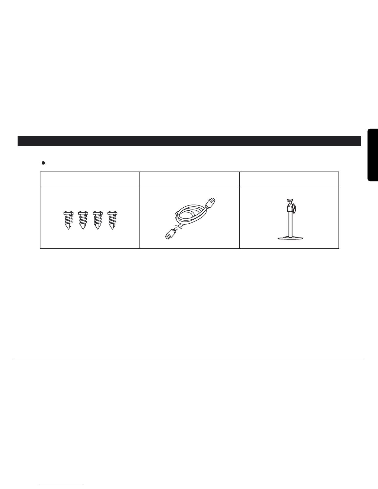
ACCESSORIES
Standard Accessories
Screws
Pedestal stand
6P Cable(20m)
09324 CA159 B/W camera with fixed lens
09325 CA159M B/W camera without lens C/CS
09328 CAD611 Dome B/w camera
09345 CA162WP Outdoor camera B/W
09331 CA168 B/W Camera in smoke detector housing
09333 CH112 Outdoor protective housing
09332 TLV9600 Timelapse recorder
09164 20m HQ plug&play cable 6P
09165 40m HQ plug&play cable 6P
09166 100m HQ plug&play cable 6P
09167 Cable Connector 6P
Page 20
20 MARMITEK
CARE AND MAINTENANCE
Your video observation system is an example of superior craftsmanship. Following
these precautions will give you many years of solid performance and enjoyment.
Keep your monitor & camera dry. If it does wet, wipe it dry
immediately.
Use and store your unit in normal temperature environment. Extreme
temperatures can shorten the life of electronic devices.
Handle the monitor carefully. Dropping it can cause serious damage
to the unit.
Occasionally, clean the unit with a damp cloth to keep it looking new,
Do not use harsh chemicals, cleaning solvents, or strong detergents
to clean the unit.
Keep the unit away from excessive dirt and dust. These can cause
premature wear of parts.
Note : All specifications subject to change without notice. E & OE.
Page 21
WJ1512/WJ1512Q
VIDEOÜBERWACHUNGSSYSTEM 30CM
1512/1512Q COPYRIGHT MARMITEK 2003 - ALL RIGHTS RESERVED
Page 22

22 MARMITEK
SETZEN SIE DEN MONITOR WEDER FEUCHTIGKEIT NOCH REGEN AUS. DER MONITOR KÖNNTE ZERSTÖRT
WERDEN ODER SIE KÖNNEN EINEN ELEKTRISCHEN SCHLAG ERHALTEN.
Bedeutung der Grafiksymbole
Der senkrecht stehende Blitz im gleichseitigen Dreieck warnt den Benutzer vor nicht isolierten
spannungsführenden teilen im Gerät, die einen lebensgefährlichen elektrischen Schlag verursachen könten.
Das Ausrufezeichen im gleichseitigen Dreieck weist den Benutzer auf wichtige Betriebs - und Wartungshinweise
in der gerätebegleitenden Dokumentation hin.
GERÄT NICHT ÖFFNEN
GEFÄHRLICHE SPANNUNG
VORSICHT
WARNUNG
ACHTUNG
VORSICHTSMAßNAHMEN & SYMBOLE
VORSICHT : GEFÄRLICHE SPANNUNGEN. ÖFFNEN SIE
NICHT DIE GEHÄUSEABDECKUNG. DIE BAUGRUPPEN
BENÖTIGEN KEINE WARTUNG. WARTUNG NUR DURCH
QUALIFIZIERTES PERSONAL.
Page 23

231512/1512Q
INHALTSANGABE
Einleitung .................................................................................... 24
Funktionen .................................................................................. 24
Vorsichtsmaßnahmen ................................................................. 24
Beschreibung
Monitor ............................................................................... 26-29
Kamera .....................................................................................30
Installation
Kamera .....................................................................................31
Monitor ..................................................................................... 32
Anschlüsse ................................................................................. 34
Fehlersuche ................................................................................ 35
Technische Daten
Monitor .................................................................................... 36
Kamera .................................................................................... 37
Zubehör ...................................................................................... 38
Seite
DEUTSCH
Page 24

24 MARMITEK
Sicherheit
- Dieses Gerät nur mit 230V AC betreiben.
- Sollte Flüssigkeit oder ein fester Gegenstand in das Innere des Gerätes kommen, dann schalten Sie es sofort aus und lassen es
durch qualifiziertes Personal überprüfen.
- Achten Sie auf genügend Luftzirkulation, damit keine Wärmeschäden entstehen. Stellen Sie es daher nie auf oder in die Nähe
von Material, welches dis Ventilationsschlitze blockieren könnte.
Installation
- Setzen Sie das Gerät niemals extremer Hitze, Feuchtigkeit, Staub oder mechanischen Erschütterungen aus.
- Das Gerät ist nicht wasserdicht! Eindringender Regen oder Feuchtigkeit können Schäden verursachen.
Reinigung & Allgemeinhinweise
- Den Monitor nicht direktem Sonnenlicht aussetzen oder starker Hitze. Sollte sich das Gerät erhitzt haben sollen, bitte den
Monitor vor dem Einsatz unbedingt abkühlen lassen.
- Gerät nur mit einem leicht feuchten und weichen Lappen reinigen. Benutzen Sie ein mildes Reinigungsmittel. Benutzen sie
niemals Lösungsmittel, welche die Geräteoberfläche beschädigen könnten.
- Bewahren Sie das Verpackungsmaterial und den Originalkarton für einen eventuellen zukünftigen Transport des Gerätes auf.
VORSICHTSMAßNAHMEN
Page 25

251512/1512Q
Dieses Videoüberwachungsset garantiert Ihnen Sicherheit und Komfort über viele Jahre. Es ist einfach zu installieren und fast
überall einsetzbar. Um eine optimale Funktionsweise zu ermöglichen, lesen Sie bitte dieses Handbuch sorgfältig durch und
verwahren es an einem sicheren Ort.
Ausführung & Funktionen
stabiles Gehäuse
4 Kameras anschließbar
einfache Installation und Bedienung
kompakte und leichte Bauweise
hochauflösender Monitor
Kameras auch einsetzbar bei niedrigen Lichtverhältnissen
manuelle oder automatische Umschaltung
Umschaltzeit einstellbar zwischen 3-60 Sekunden
Audioübertragung in zwei Richtungen (Monitor Kamera und Kamera Monitor)
Aufzeichnungsmöglichkeit mit VCR Langzeitrekorder
RJ11-Buchsen sowie BNC-Buchsen für Kameranschlüsse
Bitte lesen Sie die folgenden Schritte sorgfältig, bevor Sie mit der Inbetriebnahme des Systems beginnen
1. Wählen Sie einen geeigneten Installationsort für die Kamera und vermeiden dabei direkte Sonnenlichteinstrahlung.
Schützen Sie die Kamera vor Staub, Feuchtigkeit und Erschütterungen
2. Der Überwachungsmonitor darf nur mit 230 V AC betrieben werden
3. Überprüfen Sie das System vor der Installation
4. Die Linsen der Kameraobjektive nicht mit Fingern oder Gegenständen berühren
EINLEITUNG
DEUTSCH
Page 26

26 MARMITEK
VCR
OFF
ON
7
6 1 2 3
4
5
8
9 10 11 12 13
14
QUADAUTO CA1 CA2 CA3 CA4 TALK
POWER
PUSH
BESCHREIBUNG
FRONTANSICHT
Frontansicht
1. REGLER FÜR DIE KAMERAVERWEILZEIT
Einstellbare Umschaltzeit von 3~60 Sekunden. Bei Automatik-Modus mit mehr
als 1 Kamera, können Sie mit diesem Regler die Kameraverweilzeit von 3
Sekunden bis zu 60 Sekunden einstellen. Drehen des Reglers im Uhrzeigersinn ergibt eine längere Verweildauer. Bei Drehung des Reglers entgegen des
Uhrzeigersinnes ergibt sich eine kürzere Verweildauer des Kamerabildes
2. HELLIGKEITSREGLER
Helligkeitseinstellung des Monitorbildes
3. KONTRASTREGLER
Kontrasteinstellung des Monitorbildes
4. V-SYNC. REGLER
Einstellung der vertikalen Synchronisation
5. LAUTSTÄRKEREGLER
Lautstärkeeinstellung der Tonübertragung
6. VCR EIN/AUS- SCHALTER
Drücken Sie den Schalter um Bilder von einem VCR-Langzeitrekorder
anzuzeigen. Durch wiederholtes Drücken dieser Taste werden die Bilder der
Überwachungskameras angezeigt.
1) Schließen Sie den Monitor an den Rekorder und drücken Sie die Aufnahme-
Taste am Rekorder zum Aufzeichnen der Bilder .
2) Zur Wiedergabe der Bilder drücken Sie den VCR-Schalter auf dem Monitor
und dann den Play Schalter auf dem Rekorder.
7. MIKROFON
Übertragung von Audiosignalen vom Monitor zur Kamera
8. ALARM-SCHALTER EIN/AUS
Schaltet den Alarm ein bzw. aus. Die Alarmfunktion kann nur bei über den
Netzschalter eingeschaltetem Monitor aktiviert werden. Wird ein Alarm
A. Monitor-Einheit
Page 27

DEUTSCH
271512/1512Q
ausgelöst, erscheint das alarmierte Kamerabild auf dem Monitor und es
ertönt ein akustisches Signal. Durch Betätigen der betreffenden
Kameratasten kann der Alarm gestoppt werden. Nach maximal 15
Sekunden erlischt ein Alarm automatisch. Während der automatischen
Sequenzanzeige wird ein alarmiertes Kamerabild angezeigt und erst
nach Erlöschen des Alarmes wird die Sequenz wieder fortgesetzt. Um
bei vorzeitiger Alarmbestästigung den Sequenzbetrieb beizubehalten
muß die Taste "Auto" gedrückt werden.
8A. BESCHREIBUNG DER ALARMFUNKTION
Mit der Alarmfunktion können automatisch Kamerabilder von jeder
Kamera einzeln, über einen zugehörigen Alarm-Eingang angesteuert
und angezeigt werden. Die Alarmansteuerung kann z.B. über einen
Bewegungsmelder, externe Kontakte usw. erfolgen. Bei Alarmierung
wird außerdem ein Alarmausgangskontakt am Monitor aktiviert um z.B.
ein. Aufzeichnungsgerät, Sirene oder eine Beleuchtungseinrichtungen
im Alarmfall zu aktivieren. Während dieser Alarmierung (Dauer ca. 15
Sek.) ertönt zusätzlich ein deutlich hörbarer Warnton. Nachdem die
Alarmdauer beendet ist, kehrt das System in seine ursprüngliche
Betriebsart wieder zurück. Sollten während eines aktuellen Alarmes
noch andere Alarme auftreten, so werden auch diese Kamerabilder
automatisch in Folge angezeigt.
9. QUAD-TASTE (Nur auf Modell WJ1512Q)
Durch Betätigen dieser Taste wird eine Quadanzeige
(Mehrfachbildanzeige) auf dem Monitor angezeigt. Jeder
Kameraeingang wird jeweils in einem kleinen Quadrantenfenster
angezeigt. So können Sie ganz einfach bis zu 4 Kameras gleichzeitig
auf dem Monitor betrachten. Wenn Sie eine Kamera als Vollbild sehen
wollen, drücken Sie einfach die betreffende Kamerataste am Monitor.
Falls Sie wieder zurück in die Quad-Anzeige wollen, drücken Sie
erneut die Quad-Taste. Wenn der Monitor eingeschaltet wird, befindet
er sich automatisch in der Quadanzeige.
10. PROGRAMMIERUNG DER AUTO-SEQUENZ-ANZEIGE
Drücken dieser Taste schaltet die automatische Umschaltung ein.
(nochmaliges Drücken dieser Taste schaltet die automatische
Umschaltung wieder aus) In dieser Betriebsart werden automatisch alle
angeschlossenen Kameras (entsprechend der voreingestellten
Umschaltzeit) auf dem Monitor angezeigt. Halten Sie diese Taste für
ca. 3 Sek. gedrückt, gelangen Sie in den sog. Programmier-SequenzModus. Es fangen die LEDs ¸ber den vier Kameratasten an zu blinken
und durch einfaches Betätigen einer Kamerataste (LED erlischt dann)
können Sie so individuell bestimmte Kameras für die Sequenzanzeige
auswählen. Falls weniger als 4 Kameras an dem Monitor
angeschlossen sind, können Sie so sehr einfach die Sequenz auf die
vorhandenen Kameras festlegen. Somit wird eine automatische
Aufschaltung eines unbenutzten Kanales vermieden. ACHTUNG :
diese Einstellungen werden gelöscht, wenn der Monitor von der
Netzspannung getrennt wird.
11. KAMERA-TASTEN 1, 2, 3 UND 4
Drücken Sie eine dieser Tasten und Sie erhalten das entsprechende
Kamerabild auf dem Monitor.
12. SPRECHTASTE
Während des Drückens dieser Taste wird der Ton der
Monitorumgebung über ein Mikrofon zur Kamera übertragen.
13. STAND-BY POWER-SCHALTER
Sie künnen mit diesem Schalter den Monitor auf stand-by schalten.
Die Alarmverarbeitung wird hiervon nicht beeinflußt, so daß ein Alarm
signalisiert wird.
14. LED-ANZEIGEN
LED Power, Kamera 1-4, Umschalt-Autom, Quad, Sprechanzeige.
BESCHREIBUNG
Alarmausgang
COM
NC
N.O
COM Masse
NO
Öffner
NC
Schließer
Page 28

28 MARMITEK
Rückansicht
BESCHREIBUNG
RÜCKANSICHT
15. NETZSCHALTER
Dieser Schalter unterbricht die Betriebsspannung und somit alle Funktionen.
16. NETZANSCHLUß FUR BETRIEBSSPANNUNG
17. ALARMAUSGANG
Alarmkontakt (Öffner & Schließer), welcher im Alarmfall vom Monitor aktiviert
wird.
18. VIDEO-EINGANG
Anschluß für Videosignale vom Langzeitrekorder.
19. VIDEO-AUSGANG
Anschluß für Langzeitrekorder oder 2. Monitor
20. AUDIO-EINGANG
Signaleingang vom Audioverstärker oder Langzeitrekorder
21. AUDIO-AUSGANG
Anschluß für Audioverstärker oder Langzeitrekorder
23 1826 19
22
20
21
24
25
15 16 17
POWER
AC IN PUT
ALARM OUT
COM
NC
N.O
CAMERA IN PUT
V C R
IN OUT OUT
AUDIO
VIDEO
SLAVE
1234
VIDEO IN
1234
AUDIO IN
CA1 CA2 CA3 CA4
REMOTE
Page 29

DEUTSCH
291512/1512Q
22. ZWEITMONITOR-AUSGANG
Video-und Audioausgang für Ton -und Bildwiedergabe auf 2ten
Monitor (Maximale Länge der optionalen Verbindungsleitungen
beträgt 20 m)
23. KAMERA-EINGÄNGE
Hier werden bis zu 4 Kameras mit dem Monitor verbunden.
24. AUDIO EINGÄNGE 1-4
Hier kann für jede Kamera ein externes Audiosignal angeschlossen
werden.
25. BNC-KAMERAEINGÄNGE 1-4
An diesen BNC-Buchsen künnen auch herkömmliche CCTVKameras mit BNC-Steckern angeschlossen werden.
BESCHREIBUNG
Page 30

30 MARMITEK
1. Objektiv
4,3 mm Festobjektiv mit IR-LEDs für Nachtsicht
2. Mikrofon
Überträgt Töne von der Kamera zum Monitor
4. Alarm-Klemmleiste
Anschluß eines externen Alarmgebers
3. Monitorbuchse
Anschluß des Kamera/Monitor-Kabels
6. Wandarm
5. Lautsprecher
Überträgt Töne vom Monitor zur Kamera
BESCHREIBUNG
B. Kamera-Einheit
Frontansicht
Rückansicht
1
2
6
3
5
4
Page 31

DEUTSCH
311512/1512Q
INSTALLATIONSHINWEISE
1. Befestigung des Halters über 4 Schrauben an
der Decke oder der Wand
2. Abbildung der Kamera hier über den befestigten
Halter montiert.
A. Kamera-Einheit
Bei ständigem Einsatz wird eine Wandhaltermontage empfohlen.
Achtung
Die Kamera sollte nicht direkt zum Sonnenlicht hinzeigend ausgerichtet sein. Bei der Platzierung der Kamera sollte auch
auf Vermeidung von zu hoher Luftfeuchtigkeit und Regen geachtet werden, da kein Wetterschutz gegeben ist.
Als Empfehlung gilt außerdem, daß die Kamerahalterungen auf ebenen Flächen von Wänden oder Decken montiert
werden sollten. Vermeiden Sie die direkte Berührung der Linse des Objektives.
Zum Reinigen des Objektives besonders des vorderen Glasskörpers wird ein spezielles Linsentuch empfohlen.
Page 32

32 MARMITEK
INSTALLATIONSHINWEISE
1. Kamera-Anschluß
Systemkabel zwischen 1. Kamera und 1. Kameraeingang
am Monitor einstecken
2 Kamera-Anschluß
Systemkabel zwischen 2. Kamera und 2. Kameraeingang
am Monitor einstecken
3. Kamera-Anschluß
Systemkabel zwischen 3. Kamera und 3. Kameraeingang
am Monitor einstecken
4. Kamera-Anschluß
Systemkabel zwischen 4. Kamera und 4. Kameraeingang
am Monitor einstecken
Netzkabel
1-4 Kamera-Anschlüsse
Benutzen Sie das mitgelieferte Systemkabel und verbinden dies mit der Kamera und dem Monitor.
B. Monitor-Einheit
POWER
AC IN PUT
ALARM OUT
COM
NC
N.O
CAMERA IN PUT
V C R
IN OUT OUT
AUDIO
VIDEO
SLAVE
1234
VIDEO IN
1234
AUDIO IN
CA1 CA2 CA3 CA4
1 2 3 4
Monitor mit BNC-Buchsen
An diesem Monitor können auch CCD-Überwachungskameras mit einem BNC-Stecker angeschlossen werden.
Benutzen Sie hierfür die entsprechenden BNC-Buchsen (1-4) an der Rückseite des Monitors.
WICHTIGER HINWEIS : Niemals zwei Überwachungskameras gleichzeitig an einem BNC-Eingang und einem System-
Kameraeingang am Monitor betreiben. Falls Sie Kameras an den BNC-Buchsen (z.b. BNC 1) des
Monitors anschließen, dürfen keine Kameras an den entsprechenden RJ-11 Buchsen (z.B. CA 1)
angeschlossen werden!
Page 33

DEUTSCH
331512/1512Q
INSTALLATIONSHINWEISE
AUDIO/ VIDEO - Anschlüsse
Bitte gehen Sie nach folgenden Anschlußhinweisen für Langzeitrekorder vor.
Monitor Rekorder-Anschlüsse
Video-OUT Video-IN
Audio-OUT Audio-IN
Video-IN Video-OUT
Audio-IN Audio-OUT
Monitor VCR-Langzeitrekorder
Video-OUT Video-IN
Audio-OUT Audio-IN
Video-IN Video-OUT
Audio-IN Audio-OUT
Bei Anschluß eines 2. Monitors gehen Sie wie folgt vor
Video 2 OUT Video-IN
Audio 2 OUT Audio-IN
HINWEIS : Dieses Anschlußkabel befindet sich nicht im Lieferumfang. Bei dem Kabel handelt es sich um
eine Cinch-Steckverbindung. (RCA-Standard, als Option erhältlich)
Page 34

34 MARMITEK
ANSCHLUßPLAN
Kabelverbindungen
Hinweis : Benutzen Sie nicht die RCA-Anschlüsse (Cinch) für die Kameras
CAMERA 1
CAMERA 4
MONITOR
CAMERA 2
CAMERA 3
POWER
AC IN PUT
ALARM OUT
COM
NC
N.O
CAMERA IN PUT
1234
VIDEO IN
1234
AUDIO IN
CA1 CA2 CA3 CA4
V C R
IN OUT OUT
AUDIO
VIDEO
SLAVE
REMOTE
Page 35

DEUTSCH
351512/1512Q
FEHLERURSACHEN/BESEITIGUNG
Problem
Zu dunkles oder helles Bild
Keine Betriebsspannung
Schlechte Bildqualität
Bild aber kein Ton
Ton aber kein Bild
Bildausfall
Monitor
Lösung
Neueinstellung +/- der
Helligkeit oder des Kontrastes.
Überprüfen des Netzanschlußes.
Reinigen Sie die Linse des
Objektives.
Überprüfen Sie die Lautstärke
und drehen ggf. den
Lautstärkeregler nach rechts.
Überprüfen der Helligkeitsregelung
ggf. mehr Helligkeit oder Kontrast.
Zunächst ziehen Sie bitte den
Netzstecker. Überprüfen Sie
nun die Zuführung des Netzkabels.
Bevor Sie Kontakt zu Ihrem Service-Händler aufnehmen, überprüfen Sie
mögliche Fehlerquellen wie folgt.
Page 36

36 MARMITEK
TECHNISCHE DATEN
Monitor
Bildrühre 12
(31cm) s/w
Videosignal 1 Vss 75
Horizontale Bildauflösung > 800 Linien
TV-Standard CCIR (625 Linien, 50 Hz)
Videoeingänge 4 x BNC und 4 x RJ11
Audioeingänge 4 x Cinch (RCA)
Lautsprecher
Alarmzeit 15 Sek.
0.5 W
VCR Video-Ein/Ausgang 2 x BNC
VCR Audio-Ein/Ausgang 2 x Cinch
Kameraumschaltung 1~4 Videokanal (auto und man.)
Quadrantenteiler 1~4 Videokanal
Spannungsversorgung 100-240V~, 50/60Hz, 0.8A
Systemkabeltyp 6~adriges (Video-Zweidraht) RJ-11
Systemstecker RJ-11 (mit 6 Kontakten)
IN / OUT VCR Audio/Video RCA-Stecker (Cinch)
Ausgang für 2. Monitor
Audio/ Video RCA-Stecker (Cinch)
Alarm-Ausgang 3-Pin Com, NC, NO
Temperaturbereich -10 C ~ +50 C
Monitorgehäuse Metall mit Kunststoffblende
Abmessungen 315(B) x 330(T) x 305(H) mm
Gewicht 9.0 Kg
Page 37

DEUTSCH
371512/1512Q
TECHNISCHE DATEN
Kamera
Bildsensor 1/3
CCD S/W
Bildpunkte (V)582 x (H)512
297.000 Pixels
Spannungsversorgung 12 V DC (vom Monitor)
Videoausgang 1.0 Vss, 75 Ohm
eingebautes Kamera-Mikrofon
Mikrofon
Lautsprecher 0.5 W
Systemkabel 6-Pol, RJ-11
Auflösung 380 Linien
Objektivgewinde C/CS
> 45dB
0.1 Lux
3-Pol Klemmleiste
Rauschabstand
Minimalbeleuchtung
Alarmausgang
Leitungsaufnahme 2 W
Abmseeungen 50(B) x 120(T) x 50(H) mm
Gewicht 230g
Betriebstemperatur -10 C bis +50 C
Technische Änderungen oder Abweichungen behält sich der Hersteller vor !
Page 38

38 MARMITEK
ZUBEHÜR
Standardzubehür
Schrauben
Montage-Arm
Kabel (20m)
09324 CA159 S/W Kamera festes Objektiv
09325 CA159M S/W Kamera ohne Objektiv C/CS
09328 CAD611 S/W Domekamera
09345 CA162WP Aussenkamera S/W
09331 CA168 S/W Kamera in Rauchmeldergeh.
09333 CH112 Aluminiumgehäuse Aussen
09332 TLV9600 Time-lapse-recorder
09164 20m HQ plug&play cable 6P
09165 40m HQ plug&play cable 6P
09166 100m HQ plug&play cable 6P
09167 Kabelkupplung 6P
Page 39

DEUTSCH
391512/1512Q
WARTUNG
Für einen störungsfreien Betrieb Ihres Video Überwachungssystemes beachten Sie
bitte folgende Hinweise :
1) Halten Sie Kamera und Monitor von Feuchtigkeit fern
2) Setzen Sie Kamera und Monitor niemals extremen Temperaturen aus
3) Transportieren Sie den Monitor vorsichtig. Starke Stöße können die Bildröhre zerstören
4) Benutzen Sie einen trockenen Lappen zum Reinigen des Monitors. Lösungshaltige
Putzmittel oder Scheuermittel können das Monitorgehäuse zerstören
5) Halten Sie Kamera und Monitor von Dreck & Staub fern
Page 40

Page 41

WJ1512/WJ1512Q
SYSTÈME DE VIDÉO SURVEILLANCE, 30 CM NOIR/BLANC
090103 • 1512 /1512 Q COPYRIGHT MARMITEK 2003 - ALL RIGHTS RESERVED
Page 42

Toutes nos félicitations ! Vous avez opté pour un système de vidéo surveillance Marmitek d’une précision extrême. Les systèmes de vidéo surveillance
proposés par Marmitek sont simples à raccorder et vous procureront un sentiment de sécurité pendant de nombreuses années. Tous les accessoires
dont vous avez besoin pour l’installation sont inclus dans le kit. Si, par la suite, vous souhaitez étendre votre système, vous pouvez le faire au moyen
de caméras et d’accessoires large bande. Vous trouverez de plus amples informations sur le site Internet www.marmitek.com
Avant de commencer, veuillez lire attentivement le mode d’emploi. Conservez-le précieusement pour une utilisation future.
CARACTERISTIQUES
• Circuit électronique fiable garant d’images de qualité supérieure
• Raccordement de 4 caméras maximum
• Facilité de raccordement et d’utilisation
• Appareil compact, léger et polyvalent
• Moniteur haute résolution
• Nécessite peu de lumière
• Commutation manuelle ou automatique entre les différentes caméras
• Intervalle de commutation entre deux caméras réglable entre 3 et 60 secondes
• Monitoring audio à 2 directions
• Sortie vidéo pour magnétoscope ou magnétoscope image par image
Câble caméra pouvant être rallongé jusque maximum 100 mètres (jusqu’à 300 mètres avec amplificateur AC71 – N° art. 09336)
LISEZ ATTENTIVEMENT LES CONSIGNES DE SÉCURITÉ SUIVANTES AVANT DE RACCORDER VOTRE SYSTÈME OU DE L’UTILISER:
1. Choisissez l’endroit où vous allez placer la caméra de façon telle à ce que l’appareil ne soit pas exposé à une source de lumière directe (par
exemple, la lumière du soleil). En outre, votre appareil doit être protégé contre l’humidité et les vibrations.
2. Le moniteur ne peut être raccordé que sur une source de tension telle qu’elle est prescrite dans les spécifications techniques. Veillez à raccorder l’appareil uniquement sur une prise de courant murale mise à la terre comme il se doit. Utilisez de préférence le moniteur dans des
installations dotées d’un différentiel et d’une protection contre les surtensions.
3. Contrôlez que le système fonctionne convenablement avant de l’installer définitivement.
4. Nettoyez l’appareil uniquement après avoir retiré la fiche de la prise de courant. Utilisez exclusivement des chiffons légèrement humides.
N’utilisez JAMAIS des aérosols ou sprays nettoyants
5. Veillez à placer le moniteur sur un support stable et résistant.
42 MARMITEK
Page 43

6. Veillez à ce que votre moniteur et votre caméra soient dans un endroit bien sec. Si malgré tout, déconnectez immédiatement l’appareil et
faites-le contrôler par un réparateur spécialisé !
7. Veillez à ce que les appareils ne soient pas exposés à d’importantes sources de poussière ou de crasse car cela risque de provoquer une usure
prématurée des composants.
8. Les trous et ouvertures de ventilation pratiqués dans le boîtier sont destinés à assurer une ventilation suffisante afin de garantir un fonction-
nement fiable. Ces ouvertures ne peuvent en aucun cas être obturées ou recouvertes. N’installez jamais votre appareil à proximité d’un radiateur. En outre, l’appareil ne doit jamais être placé dans des locaux exigus ou clos, par exemple dans des armoires, à moins que ceux-ci ne soient
ventilés convenablement.
9. Confiez les réparations éventuelles exclusivement à des spécialistes. En ouvrant ou en enlevant le boîtier, vous vous exposez à un risque de
chocs électriques.
10. Utilisez l’appareil uniquement à des températures normales. Des températures extrêmes risquent d’avoir un effet négatif sur votre appareil.
11. Manipulez le moniteur avec précaution. Si vous le laissez tomber, il risque d’être sérieusement endommagé. Après une chute, faites toujours
contrôler l’appareil par un réparateur spécialisé avant de l’utiliser à nouveau.
12. Utilisez exclusivement le cordon fourni d’origine et contrôlez-le pour voir s’il n’est pas endommagé. Le cas échéant, remplacez-le immédiate-
ment !
13. L’appareil est revêtu du marquage CE et satisfait aux exigences d’utilisation en vigueur dans les pays de l’Union Européenne.
Remarque : les caractéristiques sont présentées sous réserve et peuvent être modifiées sans avertissement préalable.
431512/1512Q
FRANÇAIS
Page 44

DESCRIPTION DES COMPOSANTS
VUE AVANT
1. BOUTON DE RÉGLAGE DU TEMPS
Ce bouton vous permet de régler un intervalle de commutation s’échelonnant
entre 3 et 60 secondes. Lorsque le système est réglé sur ‘automatique’ et que
plusieurs caméras sont raccordées, grâce à ce bouton, vous pouvez régler la
durée pendant laquelle vous souhaitez regarder l’image de la caméra correspondante. En tournant ce bouton dans le sens des aiguilles d’une montre, vous pouvez augmenter l’intervalle de commutation jusque maximum 60 secondes. En
tournant le bouton dans le sens contraire des aiguilles d’une montre, vous pouvez
le réduire jusque minimum 3 secondes.
2. BOUTON DE RÉGLAGE DE LA LUMINOSITÉ
Ce bouton vous permet d’accentuer ou d’atténuer la luminosité de l’écran.
3. BOUTON DE RÉGLAGE DU CONTRASTE
Ce bouton vous permet d’accentuer ou d’atténuer le contraste de l’écran
4. BOUTON DE RÉGLAGE DE LA STABILITÉ VERTICALE (V-HOLD)
Ce bouton vous permet de synchroniser l’image verticalement et d’éviter le
défilement de l’image.
5. BOUTON DE RÉGLAGE DU VOLUME
Ce bouton vous permet d’augmenter ou de diminuer le volume.
6. INTERRUPTEUR D’ALIMENTATION DU MAGNÉTOSCOPE
(MARCHE/ARRÊT)
Pour contrôler le signal du magnétoscope, poussez une seule fois sur la touche
VCR. Repoussez sur cette touche, pour repasser à l’image de la caméra.
44 MARMITEK
QUADAUTO CA1 CA2 CA3 CA4 TALK
POWER
VCR
OFFON
7
6 1 2 3
4
5
8
9 10 11 12 13
14
PUSH
Page 45

Comment regarder les images vidéo enregistrées?
1) Raccordez le moniteur sur le magnétoscope et appuyez sur le bouton RECORD sur le magnétoscope afin de lancer l’enregistrement. Le magnéto-
scope enregistrera l’image telle qu’elle apparaît sur le moniteur.
2) Pour visualiser les images enregistrées, appuyez une seule fois sur la touche VCR et sur le bouton PLAY de votre magnétoscope.
7. MICROPHONE
Ce microphone vous permet de transmettre votre voix et d’autres sons éventuels vers le haut-parleur de la caméra active.
8. INTERRUPTEUR D’ALARME
Connecte ou déconnecte la fonction d’alarme. Lors de la mise en circuit du moniteur, la fonction d’alarme est automatiquement connectée.
DESCRIPTION DE LA FONCTION D’ALARME
La fonction d’alarme permet de commander automatiquement l’image grâce à un détecteur de mouvements installé sur la caméra (Modèle AC10
N° d’art. 09335).
Lorsque le détecteur de mouvements s’active, le système passe automatiquement à la caméra
correspondante. En même temps, il émet un signal d’alarme pendant 15 secondes. Après 15
secondes, le système repasse automatiquement dans la position configurée.
Un enregistreur TimeLapse (image par image) raccordé peut également être activé automatiquement si celui-ci est réglé en mode Event. Le modèle X2 est doté d’un contact de commutation (tant Normally Open/normalement ouvert que Normally Close/normalement fermé) qui
se déclenche en cas d’alarme.
9. INTERRUPTEUR QUADRAVISION (UNIQUEMENT MODELE MARMITEK 1512Q)
Cet interrupteur permet un rendu quadravision (quad) pour l’affichage simultané de 4 caméras maximum. Lorsque vous souhaitez un affichage plein
écran d’une seule des images, vous pouvez également appuyer sur la touche de la caméra correspondante (8). Si vous appuyez sur la touche Quad
(Y), le système passe de nouveau en mode quadravision. Si la fonction alarme (X) est activée, la commutation se fait automatiquement.
Lorsque vous allumez le moniteur, la fonction Quad s’enclenche automatiquement.
10. COMMUTATEUR AUTOMATIQUE DES CANAUX (PROGRAMMABLE)
Ce commutateur vous permet de connecter ou de déconnecter automatiquement un canal. En mode ‘auto’, le système passera automatiquement
451512/1512Q
FRANÇAIS
ALARM OUT
COM
NC
N.O
COM = common
NO = normally open
NC = normaly closed
Page 46

d’une caméra à l’autre. L’intervalle de temps est déterminé au moyen du bouton de réglage ‘time’. La commutation automatique des canaux est
également programmable. Pour ce faire, maintenez le bouton ‘auto’ enfoncé pendant environ 3 secondes. La petite lampe LED va clignoter. Pendant
que cette lampe clignote, vous devez enfoncer les touches de sélection de la caméra correspondante (dans l’ordre où vous souhaitez que les images
soient présentées). Lorsque vous avez terminé l’encodage, appuyez une nouvelle fois sur le bouton ‘auto’ afin d’enregistrer l’encodage dans la
mémoire.
Important : ces encodages s’imposent absolument lorsque moins de 4 caméras sont raccordées afin d’éviter d’être connecté sur un écran vide.
N.B. : La mémoire est effacée lorsque la tension fait défaut.
11. TOUCHES DE SÉLECTION DES CAMÉRAS 1, 2, 3 ET 4.
Appuyez sur une des 4 touches de sélection des caméras afin de visualiser l’image de la caméra correspondante.
12. BOUTON TALK
Le moniteur est doté d’un microphone incorporé. Appuyez sur le bouton TALK (et maintenez-le enfoncé) afin de parler dans le haut-parleur incorporé
dans la caméra. Si vous relâchez la touche, via le moniteur, vous entendrez de nouveau entendre les sons enregistrés par le microphone de la caméra.
13. BOUTON MARCHE/ARRÊT
Appuyez une seule fois pour mettre l’appareil sous tension. L’écran affiche les caméras programmées. Appuyez une nouvelle fois sur le bouton pour
déconnecter le système.
14. INDICATEURS LED
Pour différentes fonctions : ‘power’, ‘auto’, talk, (Quad sur le modèle 1512Q), et caméras 1, 2, 3 et 4.
46 MARMITEK
Page 47

VUE ARRIERE
15 INTERRUPTEUR MARCHE/ARRET
Pour allumer et éteindre le moniteur
16. RACCCORDEMENT DU CÂBLE D’ALIMENTATION
17. CONTACTS D’ALARME (SORTIE)
Contact NO (Normally Open ) et NC (Normally closed) pour le raccordement de fonctions
d’alarmes externes ou pour le déclenchement d’un enregistreur TimeLapse en Mode
Event.
Fonctionne uniquement si la fonction Alarme est connectée.
18. ENTRÉE VIDÉO
Entrée pour le signal vidéo de votre magnétoscope ou magnétoscope image par image
(pour la restitution de l’image)
19. SORTIE VIDÉO
Sortie pour le signal vidéo de votre magnétoscope ou magnétoscope image par image
(pour l’enregistrement).
20. ENTRÉE AUDIO
Entrée pour le signal audio de votre magnétoscope ou magnétoscope image par image
(pour la restitution de l’image)
21. SORTIE AUDIO
Sortie pour le signal audio de votre magnétoscope ou magnétoscope image par image
(pour l’enregistrement)
471512/1512Q
FRANÇAIS
23 1826 19
22
20
21
24
25
15 16 17
POWER
AC IN PUT
ALARM OUT
COM
NC
N.O
CAMERA IN PUT
V C R
IN OUT OUT
AUDIO
VIDEO
SLAVE
1234
VIDEO IN
1234
AUDIO IN
CA1 CA2 CA3 CA4
REMOTE
D
E
F
A
B
C
A) B+
B) Audio entrée
C) Audio B+
D) Video entrée
E) Audio sortie
F) N.C (Fermé Normal)
Page 48

22. SORTIE DU MONITEUR ESCLAVE
Sortie audio et vidéo pour le raccordement d’un moniteur complémentaire. Raccordez le moniteur supplémentaire en utilisant un câble coaxial
blindé. La longueur maximale recommandée de ce câble est de 20 mètres. Les câbles plus longs engendrent des pertes de qualité.
23. RACCORDEMENTS ‘PLUG&PLAY’ POUR LES CAMÉRAS.
Vous pouvez très simplement y raccorder vos caméras avec le câble système Marmitek. Ce câble permet de raccorder le signal audio et vidéo et
également d’alimenter la caméra en électricité. Il est également possible de raccorder un détecteur de mouvements sur la caméra Marmitek (voir
X1) sans aucun câblage complémentaire.
ATTENTION : ne pas utiliser cette entrée simultanément lorsqu’une caméra est raccordée sur l’entrée BNC (20).
24. ENTREES AUDIO
Sur ces entrées en boucle, il est possible de proposer un signal audio
25. ENTREES CAMERA BNC
Sur ces entrées, il est possible de raccorder des caméras au moyen d’un câble coaxial BNC. Si l’on utilise cette entrée, les caméras doivent être alimentées de façon externe.
ATTENTION : Ne pas utiliser cette entrée simultanément lorsqu’une caméra est raccordée au moyen du câble système (13)
26. REMOTE (COMMANDE À DISTANCE)
Pas d’application
48 MARMITEK
Page 49

UNITÉ CAMÉRA
1. LENTILLE DE LA CAMÉRA CCD
Lentille fixe avec éclairage infrarouge incorporé pour
vision de nuit
2. MICROPHONE
Permet de capter les sons à proximité de la caméra
3. SORTIE CAMÉRA
En vue du raccordement du câble qui relie le moniteur
4. TERMINAL D’ALARME
5. HAUT-PARLEUR
Le haut-parleur transmet le son à partir du moniteur
6. ETRIER DE FIXATION POUR LA CAMÉRA
491512/1512Q
FRANÇAIS
Vue avant Vue arrière
3
5
4
1
2
6
Page 50

INSTALLATION
INSTALLATION DE LA CAMÉRA
Installation permanente au moyen de l’étrier de fixation
1. Fixez l’étrier au moyen de 4 vis.
2. Fixez la caméra sur l’étrier et serrez la vis.
Attention : Choisissez l’endroit où vous allez placer la caméra de façon telle à ce que l’appareil ne soit pas exposé à une source de lumière directe
(par exemple, la lumière du soleil). En outre, votre appareil doit être protégé contre l’humidité et les vibrations. L’étrier de fixation doit être fixé sur
un support résistant, par exemple un mur ou un plafond. Ne touchez pas le verre de la lentille car vous risqueriez d’endommager la couche de protection sensible de la lentille. Pour nettoyer la lentille, utilisez un chiffon spécialement destiné à cet effet que vous trouverez dans tous les magasins
spécialisés.
50 MARMITEK
Page 51

INSTALLATION DU MONITEUR
Raccordements pour 1-4 caméras
Le câble ‘plug&play’ fourni avec le système vous permet de raccorder la caméra
sur le moniteur conformément à l’illustration ci-dessous.
Placez la fiche mâle dans une prise de courant de 230V.
Mettez le moniteur sous tension en appuyant sur le bouton vert.
1. Point de raccordement Caméra 1
Raccordez la caméra 1 sur ce point de raccordement
2. Point de raccordement Caméra 2
Raccordez la caméra 2 sur ce point de raccordement
3. Point de raccordement Caméra 3
Raccordez la caméra 3 sur ce point de raccordement
4. Point de raccordement Caméra 4
Raccordez la caméra 4 sur ce point de raccordement
CÂBLE D’ALIMENTATION
Raccordements Audio/vidéo.
Raccordez votre magnétoscope ou votre magnétoscope image par image de la façon suivante :
Moniteur Magnétoscope
magnétoscope image par image
Video OUT Video IN
Audio OUT Audio IN
Video IN Video OUT
Audio IN Audio OUT
Attention : le câble dont vous avez besoin pour ce raccordement n’est pas fourni avec l’appareil. Pour ce faire, vous devez utiliser un ‘câble coaxial tulipe’.
511512/1512Q
FRANÇAIS
POWER
AC IN PUT
ALARM OUT
COM
NC
N.O
CAMERA IN PUT
V C R
IN OUT OUT
AUDIO
VIDEO
SLAVE
1234
VIDEO IN
1234
AUDIO IN
CA1 CA2 CA3 CA4
REMOTE
1 2 3 4
Page 52

52 MARMITEK
CAMERA 1
CAMERA 4
MONITOR
CAMERA 2
CAMERA 3
POWER
AC IN PUT
ALARM OUT
COM
NC
N.O
CAMERA IN PUT
1234
VIDEO IN
1234
AUDIO IN
CA1 CA2 CA3 CA4
V C R
IN OUT OUT
AUDIO
VIDEO
SLAVE
REMOTE
RACCORDEMENTS DES CÂBLES :
Attention : n’utilisez pas les fiches tulipes pour raccorder les caméras.
Placez les petites broches mâles du câble DIN ‘plug&play’ sur le moniteur en veillant à ce que la flèche soit orientée vers le haut. Placez les petites
broches mâles sur la caméra, la flèche étant orientée vers le bas.
Page 53

531512/1512Q
FRANÇAIS
RÉSOLUTION DES PROBLÈMES
PROBLÈMES RELATIFS AU MONITEUR REMÈDE
Pas d’image, pas de son Contrôlez que le moniteur soit bien en mode ‘VCR’. Testez le bouton ‘VCR on/off’ pour
repasser au réglage normal.
Plusieurs images sur votre écran Tournez le bouton ‘V-hold’.
L’image se déplace vers le haut ou Tournez le bouton ‘V-hold’. vers le bas
L’image est trop sombre ou trop foncée Tournez les boutons ‘Contrast ‘ et ‘Brightness’.
Il ne se passe rien du tout Contrôlez si l’appareil est sous tension.
Mauvaise qualité de l’image Nettoyez la lentille de la caméra. Tournez les boutons ‘Contrast ‘ et ‘Brightness’.
Vous avez l’image mais pas le son Tournez le bouton ‘volume’.
Vous avez le son mais pas l’image Tournez les boutons ‘Contrast ‘ et ‘Brightness’.
L’image se ‘rétrécit’ Contrôlez la source de tension.
Pour de plus amples informations, vous pouvez consulter notre site web : www.marmitek.com
Monitor
Page 54

FICHE TECHNIQUES
MONITEUR
Tube-image 30 CRT noir/blanc
Niveau entrée vidéo 1.0V p-p
Impédance de la sortie vidéo 75 Ohm
Niveau sortie vidéo 1.0V p-p
Fréquence de balayage horizontal 15.625 / 15.734 KHz
Fréquence de balayage vertical 50 / 60 Hz
Résolution horizontale 800 lignes
Rapport signal/bruit 50 dB ou meilleur
Gain vidéo plus de 30dB
Température d’exploitation -10˚C ~+50˚C
Consommation moins de 40W
Dimensions 315 x 330 x 305mm (lxpxh)
Poids 9,0 kg
54 MARMITEK
CAMÉRA
Capteur d’image CCD 1/3" noir/blanc
Intensité lumineuse min. 0,1 Lux
Vision de nuit ± 1m au moyen de Leds
infrarouges
Résolution plus de 380 lignes TV
Nombre de pixels (V)492 x H(512)
251.000 pixels
Système vidéo CCIR
Tension 12V (alimenté par moniteur)
Sortie vidéo 1Vpp
Microphone incorporé electret
Haut-parleur 0,5W
Connecteur mini DIN 6P (plug&play)
Lentille lentille fixe 4,3mm, 73˚
Iris automatique 1/100.000 sec.
Rapport signal/bruit plus de 45 dB
Température d’exploitation -10˚C ~+50˚C
Consommation 2W
Dimension 50x70x50mm (lxpxh)
Poids 230g
Boîtier plastique ABS blanc
Accessoires compris câble HQ plug&play de
20 mètres, étrier de fixation
Page 55

551512/1512Q
FRANÇAIS
ACCESSOIRES EN OPTION
N° D’ART. DESCRIPTION
09324 Caméra CA159 Z/W avec lentille fixe (caméra identique à celle du kit)
09325 Caméra C/CS CA159M Z/W sans lentille (lentille 4,6,12,16mm)
09328 Caméra dôme CAD611 Z/W résistante aux chocs
09345 Caméra extérieure CA162WP Z/W
09331 Caméra CA168 Z/W dans boîtier détecteur de fumée
09333 Boîtier extérieur CH112 pour CA159/CA159M
09332 Magnétoscope image par image TLV9600
09164 Câble 20m HQ plug&play, Mini DIN 6 P
09165 Câble 40m HQ plug&play, Mini DIN 6 P
09166 Câble 100m HQ plug&play, Mini DIN 6 P
09167 Connecteur Mini DIN 6P/6P
Page 56

Page 57

WJ1512/WJ1512Q
MARMITEK OBSERVATIESYSTEEM, 30 CM ZWART/WIT
090103 • 1512 /1512 Q COPYRIGHT MARMITEK 2003 - ALL RIGHTS RESERVED
Page 58

Gefeliciteerd! U heeft gekozen voor een Marmitek observatiesysteem, gefabriceerd met grote zorg. Observatiesystemen van Marmitek zijn eenvoudig
aan te sluiten, en geven u vele jaren een veilig gevoel. Als u uw systeem later wilt uitbreiden, is dit mogelijk met de brede lijn camera’s en accessoires.
Meer informatie vindt u op www.marmitek.com
Lees voordat u begint aandachtig de gebruiksaanwijzing, en bewaar deze voor toekomstig gebruik.
KENMERKEN
• Betrouwbaar electronisch circuit om een beeld van hoge kwaliteit te garanderen
• Maximaal 4 camera’s aan te sluiten
• Makkelijk aan te sluiten en te bedienen
• Compact, lichtgewicht en veelzijdig
• Monitor met hoge resolutie
• Schakelen tussen camera’s kan handmatig en automatisch
• Schakel-interval tussen camera’s in te stellen tussen 3 en 60 seconden
• 2-weg audio-monitoring
• Video-uitgang voor video- of timelapserecorder
• Camerakabel te verlengen tot maximaal 100 meter (of tot 300 meter met versterkerbox AC71 – artikelnummer 09336)
VERZORGING, ONDERHOUD EN AANWIJZINGEN VOOR VEILIG GEBRUIK
LEES DE VOLGENDE VOORZORGSMAATREGELEN VOORDAT U HET SYSTEEM AANSLUIT OF IN GEBRUIK NEEMT
1. Kies de locatie zodanig, dat u het apparaat niet blootstelt aan een directe lichtbron zoals zonlicht. Tevens dient het apparaat te worden
beschermd tegen vocht en trillingen.
2. De monitor dient slechts te worden aangesloten op een spanningsbron zoals omschreven in de technische specificaties. Zorg ervoor dat het
toestel alleen op een juist geaarde wandcontactdoos is aangesloten. Gebruik de monitor bij voorkeur in installaties voorzien van een
aardlekschakelaar en een overspanningsbeveiliging.
3. Controleer of het systeem goed functioneert, voordat u het definitief installeert.
4. Reinig het apparaat pas nadat u de stekker uit het stopcontact heeft genomen. Gebuik uitsluitend een licht vochtige doek. Gebruik NOOIT
58 MARMITEK
Page 59

reinigings spuitbussen of sprays.
5. Zorg voor een stabiele en stevige ondergrond voor plaatsing van de monitor.
6. Houd uw monitor en camera droog. Als ze onverhoopt toch nat worden, meteen uitschakelen het apparaat door een gekwalificeerd ser-
vicebedrijf na laten kijken!
7. Houd de apparaten uit de buurt van extreem stof en vuil. Dit kan vroegtijdige slijtage van onderdelen veroorzaken.
8. Ventilatiegaten en openingen in de behuizing zijn gemaakt voor de benodigde ventilatie, zodat een betrouwbare werking gegarandeerd is.
Deze openingen mogen NOOIT afgesloten of bedekt te worden. Plaats uw apparatuur nooit op of in de buurt van een radiator. Tevens dient de
apparatuur niet geplaatst te worden in kleine, afgesloten ruimtes zoals kasten, tenzij voorzien van goede ventilatie.
9. Laat eventuele reparatie uitsluitend over aan specialisten. Door de behuizing te openen of verwijderen riskeert u gevaarlijke electrische
schokken.
10. Gebruik uw apparatuur alleen bij normale temperaturen. Extreme temperaturen kunnen de levensduur van uw apparatuur negatief beinvloe-
den.
11. Wees voorzichtig met de monitor. Als u deze laat vallen kan dit ernstige schade aan het apparaat toebrengen. Laat het apparaat na een val
eerst nakijken door een gekwalificeerd servicebedrijf alvorens het weer in gebruik te nemen.
12. Gebruik uitsluitend bijgeleverde netsnoer en controleer deze op beschadigingen.
Indien de netsnoer is beschadigd deze onmiddellijk vervangen!
13. Dit apparatuur is voorzien van het CE-keurmerk en voldoet aan de eisen voor gebruik in landen van de Europese Unie.
591512/1512Q
NEDERLANDS
Page 60

BESCHRIJVING VAN DE ONDERDELEN
VOORAANZICHT
1. INSTELKNOP VOOR DE TIJD
Met deze knop kunt u een schakel-interval instellen tussen 3 en 60 seconden.
Wanneer het syteem is ingesteld op ‘automatisch’, met meer
dan een camera aangesloten, kunt u met deze knop instellen hoe lang
u naar het beeld van de betreffende camera wilt kijken. Door de knop
met de klok mee te draaien, verhoogt u de intervaltijd, tot een maximum
van 60 seconden. Door de knop tegen de klok in te draaien verlaagt
u de intervaltijd, tot een minimum van 3 seconden.
2. HELDERHEID-KNOP
Hiermee kunt u de helderheid van het scherm verhogen of verlagen
3. CONTRASTKNOP
Hiermee kunt u het contrast van het scherm verhogen of verlagen
4. VERTICAL HOLD KNOP
Hiermee kunt u het beeld verticaal synchroniseren om lopend
beeld te voorkomen
5. VOLUMEKNOP
Hiermee kunt u het volume verhogen of verlagen.
6. VIDEORECORDER AAN/UIT SCHAKELAAR
Om het signaal van de videorecorder te bekijken drukt u eenmaal
op de VCR-toets. Druk nogmaals om terug te schakelen naar het
beeld van de camera.
60 MARMITEK
QUADAUTO CA1 CA2 CA3 CA4 TALK
POWER
VCR
OFFON
7
6 1 2 3
4
5
8
9 10 11 12 13
14
PUSH
Page 61

Hoe kunt u de opgenomen videobeelden terugkijken?
1) Sluit de monitor aan op de videorecorder en activeer RECORD op de videorecorder om de opname te starten. De videorecorder zal
het beeld opnemen zoals dit wordt weergegeven op de monitor.
2) Om de opgenomen beelden terug te kijken, druk eenmaal de VCR-toets, en activeer PLAY op uw videorecorder.
7. MICROFOON
De monitor heeft een ingebouwde microfoon. Druk op de talk-knop (en houd deze ingedrukt) om te spreken door de luidspreker welke is ingebouwd
in de camera. Als u de toets loslaat, hoort u via de monitor weer het geluid wat wordt opgenomen door de microfoon in de camera.
8. ALARMSCHAKELAAR
Schakelt de alarmfunctie uit of aan. Bij het inschakelen van de monitor wordt de alarmfunctie automatisch ingeschakeld.
BESCHRIJVING VAN DE ALARMFUNCTIE:
Met de alarmfunctie kan het beeld automatisch worden geschakeld door een op de camera aangebrachte bewegingsmelder (model AC10, artikelnummer 09335).
Bij het activeren van de bewegingsmelder wordt automatisch op de desbetreffende camera
overgeschakeld. Tegelijkertijd hoort u een alarmsignaal gedurende 15 seconden. Na 15 seconden gaat het systeem weer automatisch in de ingestelde stand. Ook kan automatisch een
aangesloten timelapse recorder worden geactiveerd indien deze in de zogenaamde ‘event
mode’ is ingesteld. Op de achterzijde is een schakelcontact voorhanden (zowel ‘normally
open’ als ‘normally closed’, wat in geval van alarm wordt getriggerd.
9. QUAD-SCHAKELAAR (ALLEEN OP MODEL MARMITEK 1512Q)
Hiermee schakelt u de kwadrant (quad) weergave in voor gelijktijdige weergave tot vier camera’s. Wanneer u één van de camerabeelden op het
gehele vlak wilt zien, kunt u op de desbetreffende camerakeuzetoets (11) drukken. Met de Quad-toets (9) schakelt u weer over op kwadrantweergave. Indien de alarmfunctie (8) is geactiveerd, gebeurt het omschakelen automatisch. Bij het inschakelen van de monitor wordt de quad-functie
automatisch ingeschakeld.
10. PROGRAMMEERBARE AUTOMATISCHE KANAALSCHAKELAAR
Hiermee schakelt u de automatische kanaalschakeling in of uit. In de ‘auto’-modus zal het systeem automatisch schakelen tussen de ingestelde
611512/1512Q
NEDERLANDS
ALARM OUT
COM
NC
N.O
COM = common
NO = normaal open
NC = normaal dicht
Page 62

camera’s. Het tijdsinterval wordt bepaald door de regelknop ‘time’. De automatische kanaalschakeling is ook programmeerbaar. Houd hiervoor
de ‘auto’-knop gedurende 3 seconden ingedrukt. Het LED-lampje zal hierdoor gaan knipperen. Terwijl dit lampje knippert dient u de betreffende
camerakeuze-toetsen in te drukken (in de volgorde waarin u wilt dat de beelden worden weergegeven). Als u klaar bent met de invoer
drukt u nogmaals op de ‘auto’-knop om de invoer op te slaan in het geheugen.
Belangrijk: Deze handelingen dienen te worden uitgevoerd wanneer er minder dan 4 camera’s zijn aangesloten, om te voorkomen dat er
naar een leeg scherm wordt geschakeld.
N.B: Het geheugen wordt gewist als de spanning wegvalt.
11. CAMERAKEUZE-TOETSEN 1, 2, 3 EN 4.
Druk een van de 4 camerakeuze-toetsen om het beeld van de desbetreffende camera weer te geven.
12. TALK-KNOP
Druk op deze knop (en houd deze ingedrukt) om te spreken door de luidspreker welke is ingebouwd in de camera. Als u de toets loslaat, hoort u via
de monitor weer het geluid wat wordt opgenomen door de microfoon in de camera.
13. AAN/UIT SCHAKELAAR
Druk eenmaal in om de spanning in te schakelen. Het scherm geeft de geprogrammeerde camera’s weer. Druk de knop nogmaals in om het
systeem uit te schakelen.
14. LED-INDICATOREN
Voor diverse functies: ‘power’, ‘auto’, (Quad alleen bij model 1512Q), camera’s 1, 2, 3 en 4.
62 MARMITEK
Page 63

ACHTERAANZICHT
15. AAN/UIT SCHAKELAAR
Voor het in- en uitschakelen van de monitor.
16. AANSLUITING NETVOEDINGSKABEL
17. ALARMCONTACTEN (UITGANG)
Een NO (Normally open) en NC (Normally closed) contact voor het aansluiten van externe
alarmfuncties of het triggeren van een Timelapse recorder in de Event mode. Werkt alleen
indien de Alarmfunctie is ingeschakeld.
18. VIDEO-INGANG
Ingang voor videosignaal van video- of timelapse recorder (voor weergave)
19. VIDEO-UITGANG
Uitgang voor videosignaal voor video- of timelapse recorder (voor opname).
20. AUDIO-INGANG
Ingang voor audiosignaal van video- of timelapse recorder. (voor weergave)
21. AUDIO-UITGANG
Uigang voor audiosignaal voor video- of timelapse recorder. (voor opname)
22. SLAVE-MONITOR UITGANG
Audio- en video uitgang voor het aansluiten van een extra monitor. Sluit de extra monitor
aan met een afgeschermde tulpkabel. De aanbevolen maximale lengte van deze kabel is
20 meter. Bij langere kabels treedt kwaliteitsverlies op.
23. ‘PLUG & PLAY’ AANSLUITINGEN VOOR CAMERA’S
Hierop sluit u eenvoudig uw camera’s aan met de Marmitek systeemkabel. Door gebruik
631512/1512Q
NEDERLANDS
23 1826 19
22
20
21
24
25
15 16 17
POWER
AC IN PUT
ALARM OUT
COM
NC
N.O
CAMERA IN PUT
V C R
IN OUT OUT
AUDIO
VIDEO
SLAVE
1234
VIDEO IN
1234
AUDIO IN
CA1 CA2 CA3 CA4
REMOTE
D
E
F
A
B
C
A) B+
B) Audio ingang
C) Audio B+
D) Video ingang
E) Audio uitgang
F) N.C
Page 64

van deze kabel wordt audio- en videosignaal aangesloten en op de camera gelijktijdig van voeding voorzien. Ook kan zonder extra bekabeling een
bewegingsmelder op de Marmitek-camera worden aangesloten (zie X1).
LET OP: deze ingang niet gelijktijdig gebruiken wanneer er een camera via de BNC-ingang (20) is aangesloten.
24. AUDIO INGANGEN
Op deze doorgeluste ingangen kan een audiosignaal worden aangeboden.
25. BNC CAMERA INGANGEN
Hierop kunnen camera’s met een BNC coax kabel worden aangesloten. Bij gebruik van deze ingang dienen de camera’s extern gevoed te worden.
LET OP: Deze ingang niet gelijktijdig gebruiken wanneer er een camera via de systeemkabel (13) is aangesloten.
26. REMOTE
Niet van toepassing
64 MARMITEK
Page 65

NEDERLANDS
CAMERA-UNIT
1. CCD CAMERALENS
Vaste lens met ingebouwde IR-verlichting voor
nachtzicht
2. MICROFOON
Hiermee vangt u het geluid in de buurt van de camera op
3. CAMERA-UITGANG
Hierop sluit u de kabel aan die naar de monitor
loopt
4. ALARM TERMINAL
5. LUIDSPREKER
De luidspreker geeft het geluid vanaf de monitor
door
6. CAMERA-BEUGEL
651512/1512Q
Voorzijde Achterzijde
3
5
4
1
2
6
Page 66

INSTALLATIE
De camera installeren
Permanente installatie door middel van de camerabeugel
1. bevestig de camerabeugel door middel van 4 schroeven.
2. bevestig de camera op de beugel en draai de schroef aan.
Attentie: Kies de locatie voor de camera zodanig, dat u het apparaat niet blootstelt aan directe lichtbronnen zoals zonlicht. Tevens dient het apparaat te worden beschermd tegen vocht en trillingen. De bevestigingsbeugel moet stevig worden bevestigd op een vaste ondergrond, zoals een
muur of een plafond. Raak het glas van de lens niet aan. Hierdoor kunt u de kwetsbare beschermlaag van de lens beschadigen. Om de lens schoon
te maken dient u een speciaal hiervoor bestemd doekje te gebruiken, verkrijgbaar bij elke camera-speciaalzaak.
66 MARMITEK
Page 67

DE MONITOR INSTALLEREN
1-4 Camera-aansluitingen
Met de bijgeleverde ‘plug & play’-kabel kunt u de camera op de monitor
aansluiten zoals in onderstaande afbeelding wordt uitgelegd.
Steek de stekker in een 230V-stopcontact.
Schakel de monitor in door op de groene knop te drukken.
1. Aansluitpunt Camera 1
Sluit camera 1 aan op deze aansluiting
2. Aansluitpunt Camera 2
Sluit camera 2 aan op deze aansluiting
3. Aansluitpunt Camera 3
Sluit camera 3 aan op deze aansluiting
4. Aansluitpunt Camera 4
Sluit camera 4 aan op deze aansluiting
AUDIO/VIDEO AANSLUITINGEN.
Sluit op onderstaande manier uw videorecorder of timelapse recorder aan:
Monitor Videorecorder/
timelapse recorder
Video UIT Video IN
Audio UIT Audio IN
Video IN Video UIT
Audio IN Audio UIT
Attentie: de kabel die u nodig heeft voor deze aansluiting is niet bijgesloten. U dient hiervoor een zogenaamde ‘tulpkabel’ te gebruiken.
671512/1512Q
NEDERLANDS
POWER
AC IN PUT
ALARM OUT
COM
NC
N.O
CAMERA IN PUT
V C R
IN OUT OUT
AUDIO
VIDEO
SLAVE
1234
VIDEO IN
1234
AUDIO IN
CA1 CA2 CA3 CA4
REMOTE
1 2 3 4
Page 68

68 MARMITEK
CAMERA 1
CAMERA 4
MONITOR
CAMERA 2
CAMERA 3
POWER
AC IN PUT
ALARM OUT
COM
NC
N.O
CAMERA IN PUT
1234
VIDEO IN
1234
AUDIO IN
CA1 CA2 CA3 CA4
V C R
IN OUT OUT
AUDIO
VIDEO
SLAVE
REMOTE
KABELAANSLUITINGEN:
Attentie: gebruik de tulp aansluitingen niet om camera’s aan te sluiten.
Sluit de stekkertjes van de ‘plug & play’-mini din-kabel aan op de monitor met de pijl-afbeelding naar boven. Sluit de stekkertjes aan op de camera
met de pijl-afbeelding naar beneden.
Page 69

691512/1512Q
NEDERLANDS
PROBLEMEN OPLOSSEN
PROBLEMEN MET DE MONITOR ACTIE:
Geen beeld, geen geluid Controleer of de monitor in de ‘VCR-Mode’ is. Toets de ‘VCR on/off’ knop
Om terug te schakelen naar denormale instelling.
Meerdere beelden in uw scherm Draai aan de knop ‘V-hold’.
Het beeld schuift naar boven of beneden Draai aan de knop ‘V-hold’.
Het beeld is te licht of te donker Draai aan de knoppen ‘Contrast ‘ en ‘Brightness’.
Het apparaat doet helemaal niets Controleer of er stroomtoevoer is.
Slechte beeldkwaliteit Reinig de cameralens. Draai aan de knoppen ‘Contrast ‘ en ‘Brightness’.
U heeft beeld, maar geen geluid Draai aan de knop ‘volume’.
U heeft geluid, maar geen beeld Draai aan de knoppen ‘Contrast ‘ en ‘Brightness’.
Het beeld ‘krimpt’. Controleer de spanningsbron.
Voor meer informatie kunt u onze website bezoeken: www.marmitek.com
Monitor
Page 70

TECHNISCHE GEGEVENS:
MONITOR
Beeldbuis 25cm CRT Zwart/wit
Video input level 1.0V p-p
Video input impedantie 75 Ohm
Video output level 1.0V p-p
Horizontal scanning rate 15.625 / 15.734 KHz
Vertical scanning rate 50 / 60 Hz
Video frequency response 6MHz (+ 1dB,-3dB)
Horizontale resolutie 800 lijnen
Signaal/ruis verhouding 50 dB of beter
Video versterking meer dan 30dB
Bedrijfstemperatuur -10˚C ~+50˚C
Opgenomen vermogen minder dan 40W
Afmetingen 250x250x255mm (bxdxh)
Gewicht 4,64 kg
70 MARMITEK
CAMERA
Beeldsensor 1/3" CCD B/W
Min. lichtintensiteit 0,1 Lux
Nachtzicht ± 1m door IR Leds
Resolutie meer dan 380 TV lijnen
Aantal beeldpunten (V)492 x H(512) / 251.000 pixels
Video system CCIR
Spanning 12V (gevoed door monitor)
Video output 1Vpp
Ingebouwde microfoon electret
Luidspreker 0,5W
Connector 6P Mini DIN (plug&play)
Lens 4,3mm vaste lens, 73˚
Automatisch iris 1/100.000 sec.
Signaal/Ruis verhouding meer dan 45 dB
Bedrijfstemperatuur -10˚C ~+50˚C
Opgenomen vermogen 2W
Afmetingen 50x70x50mm (bxdxh)
Gewicht 230g
Behuizing ABS kunstof, wit
Bijgevoegde accessories 20m HQ plug&play kabel, camerabeugel
Page 71

711512/1512Q
NEDERLANDS
OPTIONELE ACCESSORIES:
Art. No. Omschrijving
09324 CA159 Z/W camera met vaste lens (zelfde camera als in set)
09325 CA159M Z/W Camera C/CS zonder lens (lens 4,6,12,16mm)
09328 CAD611 Z/W dome camera slagvast
09345 CA162WP Z/W buitencamera
09331 CA168 Z/W camera in rookdetector behuizing
09333 CH112 buitenbehuizing voor CA159/CA159M
09332 TLV9600 Timelapse recorder
09164 20m HQ plug&play kabel 6P Mini DIN
09165 40m HQ plug&play kabel 6P Mini DIN
09166 100m HQ plug&play kabel 6P Mini DIN
09167 6P/6P Mini DIN koppelstuk
VERZORGING, ONDERHOUD EN AANWIJZINGEN VOOR VEILIG GEBRUIK
• Houd uw monitor en camera droog. Als ze onverhoopt toch nat worden, meteen droogmaken!
• Houd de apparaten uit de buurt van extreem stof en vuil. Dit kan vroegtijdige slijtage van onderdelen veroorzaken.
• Ventilatiegaten en openingen in de behuizing zijn gemaakt voor de benodigde ventilatie, zodat een betrouwbare werking gegarandeerd is. Deze
openingen mogen niet afgesloten of bedekt te worden. Plaats uw apparatuur nooit op of in de buurt van een radiator. Tevens dient de apparatuur
niet geplaatst te worden in kleine, afgesloten ruimtes zoals kasten, tenzij voorzien van goede ventilatie.
• Laat eventuele reparatie over aan specialisten. Door de behuizing te openen of verwijderen riskeert u gevaarlijke electrische schokken.
• Gebruik uw apparatuur alléén bij normale temperaturen. Extreme temperaturen kunnen de levensduur van uw apparatuur negatief beinvloeden.
• Wees voorzichtig met de monitor. Als u deze laat vallen kan dit ernstige schade aan het apparaat toebrengen.
De apparatuur is voorzien van het CE-keurmerk.
Attentie: alle genoemde specificaties zijn onder voorbehoud, en kunnen zonder aankondiging wijzigen.
Page 72

CE Declaration of Conformity
We, Marmitek BV, PO BOX 4257, 5604 EG, EINDHOVEN, herewith declares that the following designated product:
WJ1512/WJ1512Q
Complies with the principal protection requirements of the Low Voltage Directive (Directive 73/23/EEC relating to electrical equipment
designed for use within certain voltage limits) based on a voluntary test.
Test standard: EN60065: 1993
Test report No.: 63.130.7.003.01
Date: 15.07.02
Evert Schaeffer
Product manager
MARMITEK BV – PO BOX 4257 – 5604 EG – EINDHOVEN – NETHERLANDS - T: 040 2122831 – F: 040 2128232 - @: info@marmitek.com - www.marmitek.com
 Loading...