

Page 1
“CMP” & “C” Series
Metered Series
AUTOMATIC WATER
CONDITIONERS
INSTALLATION, OPERATION, AND
MAINTENANCE MANUAL
FILL IN FOR FUTURE REFERENCE
MODEL NO:___________________________________________
SERIAL NO:___________________________________________
DATE INSTALLED:______________________________________
DEALER:______________________________________________
8-171 R5
Page 2
“CMP” & “C” Series Automatic Water Conditioners
( “CMP” SERIES )
SPECIFICATION TABLE
Model Number
Exchange
Capacity
Kilograms
Salt Per
Regeneration
Lbs. / Regen.
Max Service
Flow (1)
Pipe Size
In - Out Drain
Operating
Pressure
Range
Maximum
Operating
Temperature
Mineral
Tank Size
(Dia. x Ht.) (2)
Brine Tank
(Dia. x Ht. (3)
Salt Storage
Resin Volume
Electrical
Units
MAX
MID
MIN
MAX
MID
MIN
GPM 16.00 15.00 17.00 20.00 16.00 15.00
INS
INS
PSI 30-125 30-125 30-125 30-125 30-12530-125
DEG F 110 110 110 110 110 110
INS. 8 x 44 9 x 48 10 x 54 12 x 52 8 x 35 10 x 35
INS. 18 x 33 18 x 33 18 x 40 18 x 40
LBS. 375 375 375 450 250 250
CU FT. 0.75 1.00 1.5 2.00 0.75 1.00
VOLT. / FREQ.
CMP-22K
22,836
19,509
14,514
11.25
8.00
4.00
1” 1” 1” 1” 1” 1”
w w w w w w
CMP-30K CMP-40K
30,448
26,012
19,352
15.00
10.00
5.00
38,060
32,515
24,190
18.75
13.00
6.00
16.00
1”
w
30-125
110
10 x 47
18 x 33
375
1.3
CMP-45K CMP-60K
45,672
39,018
29,028
22.50
15.00
8.00
120 Volts 60 Hz
60,896
52,024
38,704
30.00
20.00
10.00
CMP-22-C
22,836
19,509
14.514
11.25
8.00
4.00
CMP-30-C
30,448
26,012
19,352
15.00
10.00
5.00
Injector
Shipping
Weight
Floor Space
Overall Ht.
Max. Drain
Flow During
Regeneration
Regeneration
Waste
Volume (6)
NOTE:
(1) Pressure drop not to exceed 15 psi.
(2) Pressure vessels are seamless and made of reinforced berglass, pressure tested at 300 psi.
(3) Brine tanks are fabricated of seamless, rigid, tough, high impact, non-toxic polyethylene.
(4) Product materials and workmanship are protected with a written warranty.
(5) Untreated water provided during all steps of regeneration.
(6) Waste water volumes based on “normal” length regeneration, 15 lb./cu.ft. salt dosage, 50 psi inlet pressure.
COLOR / CODE
LBS. 72 105 119 137 77 91
INS. 27 x 18 28 x 18 29 x 16 31 x 18 13.5 x 22.5 13.5 x 22.5
INS. 52 56 62 60 42 42
GPM
GAL. 60 80 95 120 60 75
Violet/C Red/D White/E Blue/F Violet/C White/E
1.7 2.2 2.7 3.2 1.7 2.7
White/E
110
29 x 16
54
2.7
95
2
8-171 R5
Page 3
“CMP” & “C” Series Automatic Water Conditioners
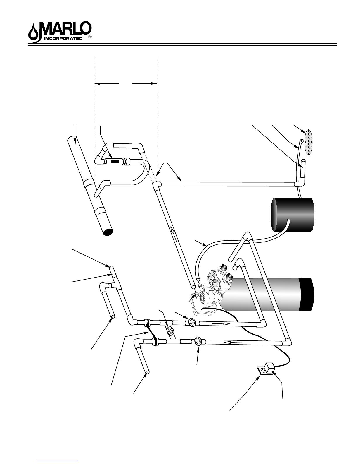
Maximum drain pipe
elevation above drain
Connection to sanitary sewer line
(optional)
Sanitary sewer line
Air gap device
port is 5 ft.
Drain
Brine Tank Overflow drain 1/2”
diameter minimum size
Drain line 1/2” diameter
minimum size
(gravity flow)
Sanitary Drain, Floor Drain or
Laundry Tubs are acceptable.
Do not make a direct connection
to the drain. An air gap must
be present.
Drain Trap
Cold hard water inlet
30 p.s.i. minimum pressure
1/2” minimum pipe size
High Pressure Warning:
If feedwater pressure is known to be above
100 p.s.i. it is strongly recommended that a
pressure reducing valve be installed at this point.
Manual Bypass Valve
(Normally Closed)
(optional)
Manual Inlet Valve
Drain Port
(optional)
Brine Line Tubing
Assembly
Brine Tank
Assembly
Softener Tank
Typical Water Softener Installation
Hard water to Sprinklers and any
dersired unsoftened fixtures
Ground Strap
Softened Water Outlet
Manual Outlet Valve
(optional)
110-125 Volt
Continuous Power Supply
3
Transformer
8-171 R5
Page 4

“CMP” & “C” Series Automatic Water Conditioners
Installation Fitting Assemblies
Installation ttings connect to the control valve or the bypass valve using nuts that only require hand tightening.
Hand tight nut connections between control valve and installation ttings, control valve and bypass valve, and bypass
valve and installation ttings allow for ease serviceability. Do not use a pipe wrench to tighten nuts on installation
ttings. Hand tighten only.
Split ring retainer design holds the nut on and allows load to be spread over the entire nut surface area reducing the
chance for leakage. The split ring design, incorporated into the installation ttings allows approximately 2 degrees
off axis alignment to the plumbing system. The installation ttings are designed to accommodate minor plumbing
misalignments but are not designed to support the weight of a system or the plumbing.
When assembling the installation tting package, connect the tting to the plumbing system rst and then attach the
nut, split ring and o-ring. Heat from soldering or solvent cements may damage the nut, split ring or o-ring. Solder joints
should be cool and solvent cements should be set before installing the nut, split ring and o-ring. Avoid getting primer
and solvent cements on any part of the o-rings or split rings, bypass valve or control valve. Solvent cements and
primers should be used in accordance with the manufacturer’s instructions.
Slip the nut onto the tting rst, then the split ring second and the o-ring last. hand tighten the nut. If the tting
is leaking, tightening the nut will not stop the leak. Remove the nut, remove the tting, and check for damage or
misalignment of the o-ring.
Do not use the pipe dope or other sealant on threads. Teon tape must be used on the threads of the 1” NPT elbow
and the 1/4” NPT connection and on the threads for the drain line connection. Teon tape is not necessary on the nut
connection or caps because of o-ring seals.
Do not use Vaseline, oils or other unacceptable lubricants on o-rings. A silicon lubricant may be used on black o-rings.
Bypass Valve
The bypass valve easily connects to the control valve body using nuts that only require hand tightening. Hand tighten
nut connections between control valve and ttings, control valve and bypass valve, and bypass valve and installation
ttings allow for easy serviceability. The split ring retainer design holds the nut on and allows load to be spread over
the entire nut surface area reducing the chance for leakage. The split ring design, incorporated into the bypass, allows
approximately 2 degrees off axis alignment to the plumbing system. The bypass is designed to accommodate minor
plumbing misalignments but is not designed to support the weight of a system or the plumbing.
Avoid getting primer and solvent cements on any part of the o-rings or split rings, bypass valve or control valve. Do not
use pipe dope or other sealant on threads. Teon tape is not necessary on the caps because of o-ring seals.
Do not use Vaseline, oil or other unacceptable lubricants on o-rings. A silicon lubricant may be used on black o-rings.
4
8-171 R5
Page 5

“CMP” & “C” Series Automatic Water Conditioners
A. GENERAL
1. Shut off all water at main supply valve.
2. Shut off the fuel supply to water heater.
3. Open faucets (hot and cold) nearest pump or water meter to relieve pressure and drain system.
4. Move softener into the installation position. Loosely attach all ttings to measure for bypass valve assembly (if used), or manual bypass valve.
5. Level the unit. Place shims under cabinet or brine tank as needed.
(Do Not use metal shims.)
6. Cut the cold water supply line as required.
7. Install the bypass valve assembly if used.
B. PLANNING INSTALLATION
1. All installation procedures must conform to local plumbing, electrical and sanitation codes and ordinances.
2. It is recommended that outside faucets for lawn service be on the hard water line, ahead of the softener,
to conserve softened water, save salt and prevent lawn damage.
3. If this isn’t practical, use the convenient integral bypass valve assembly during irrigation ows.
CAUTION: The inlet water temperature MUST NOT exceed 1200 F.
4. Do not locate softener where ambient temperature drops below 400 F.
5. Allow space around the softener for ease of servicing.
6. The softener drain lines must never be solidly connected to the sewer line. (Always provide an air gap at
the END of the drain line). Valve drain line must not be elevated over 5’ from the top of the softener on
well systems, and not over 8’ on municipal water systems.
7. The salt storage cabinet or brine tank is a gravity drain, and this drain line must be lower than the drain
tting on the side wall of the cabinet.
8. Move the softener into position and connect to bypass assembly (if used). The integral manual bypass
option is a connection which eliminates the need for a 3-valve manifold. This makes installation easier
and provides a more convenient method of bypassing.
9. IMPORTANT: Be sure that the water inlet line is connected to the “inlet” side of the bypass valve or to
the inlet tting. (Bypass valve both inlet/outlet ttings are marked.) If water lines are reverse, (inlet/outlet) resin may be forced from the water softener into the household plumbing system. If this occurs,
household plumbing system must be ushed clean.
C. CONNECT ALL FITTINGS (refer to previous page)
CAUTION: Care must be used when working with copper tubing. Do not allow the ame from torch to
contact any portion of the Valve assembly.
1. Attach 1/2” drain line to drain elbow with insert and nut. Use optional 3/4” drain ttings if drain run
exceeds 25 ft.
2. Do not elevate the drain line over 5’ above the top of the valve (8’ on municipal systems) or to exceed 25’
in length at either height.
CAUTION: An air gap must be provided upon sewer entry. (Conform to local plumbing and sanitation
codes and ordinances).
3. The salt storage cabinet or brine tank provides an overow. Attach 1/2” ID exible plastic tubing to the
overow tting and direct it to the drain. DO NOT connect to the main drain line. Use a separate gravity
ow line.
5
8-171 R5
Page 6

“CMP” & “C” Series Automatic Water Conditioners
D. PRESSURE TEST THE INSTALLATION
The plumbing system can now be checked for any possible leaks
1. Put the unit into backwash. To do this, push and hold the REGEN button for 3-5 seconds. When the
Valve stops cycling, unplug the unit. With water supply off, put the bypass into the service position.
2. Open water supply line valve very slowly. Water should escape slowly from the drain line. If water enters
too quickly, resin may be lost to the drain.
3. When all of the air has been purged from the mineral tank (water ows steadily from the drain) open the
main supply valve fully.
4. Allow water to run to drain until clear. CHECK FOR LEAKS!
5. Plug the unit back in.
6. Manually step the unit through the remaining steps, stopping at the ll cycle (to do this, push the REGEN
button. The unit will say Brine on the screen). Once the piston has stopped moving, push the REGEN
button again to the next cycle. Continue until Fill appears on the screen. The unit will now ll the brine
tank to the appropriate level. (This sequnce is for softeners with post ll brine)
7. Allow control to return to the home position.
8. Check for leaks!
9. Make sure the power cord is plugged into a properly grounded wall receptacle.
E. MANUAL REGENERATION
The user can initiate manual regeneration. The user has the option to request a manual regeneration at the
delayed regeneration time or to have the regeneration occur immediately:
1. Pressing and releasing the REGEN button. “Regen Today” will ash on the display and the regeneration
will occur at the delayed regeneration time. The user can cancel the request by pressing and releasing
the REGEN button. This method of manually initiating regeneration is not allowed when the system is set to
immediately regenerate when the gallon capacity reaches zero.
2. Pressing and holding the REGEN button for approximately 3 seconds will immediately start the regeneration
The user cannot cancel this request.
NOTE: Program Timer “Lockout” Feature
The Program Timer is initially set to allow access to all Programming, Diagnostic and History screens
The Installer can limit access to (lockout) most screens by activating the Lockout Feature.
Activating “Lockout” allows the user to view and change only Water Hardness, Days Override, Time of Regeneration
and Time of day.
Activate “Lockout” Feature: Press then NEXT then then SET CLOCK in sequence. LOC will briey appear
in the display.
De-activate “Lockout” Feature: Press then NEXT then then SET CLOCK. UNLOC will briey appear in
the display.
When in operation normal user displays such as time of day, gallons remaining or days remaining before regeneration
are shown. When stepping through a procedure if no buttons are pressed within ve minutes the display returns to a
normal user display. Any changes made prior to the ve minute time out are incorporated. The one exception is current ow rate display under the diagnostic procedure. The current ow rate display has a 30 minute time out feature.
6
8-171 R5
Page 7
“CMP” & “C” Series Automatic Water Conditioners
Control Valve Function and Cycles of Operation
This glass lled Noryl1 fully automatic control valve is designed as the primary control center to direct and regulate
all cycles of a water softener or lter. When the control valve is set up as a softener, the control valve can be set
to perform down ow or up ow regeneration with the proper piston. When the control valve is set up as a lter,
the control valve can be set to perform down ow regeneration or simply backwash. The control valve can be set
to regenerate on demand (consumption of a predetermined amount of water) and/or as a time clock (passage
of a particular number of days). The control valve can be set so that the softener can meet the Water Quality
Association (WQA) or NSF International efciency rating.
The control valve is compatible with a variety of regenerants and resin cleaners. The control valve is capable of
routing the ow of water in the necessary paths to regenerate or backwash water treatment systems. The injector
regulates the ow of brine or other regenerants. The control valve regulates the ow rates for backwashing,
rinsing and the replenishing of treated water into a regenerant tank, when applicable.
The control valve is designed to deliver high service (27 gpm @ 15 psig) and backwash (27 gpm @ 25 psig) ow
rates when the bypass has straight ttings and a 1.050” distributor. The control valve uses no traditional fasteners
(e.g. screws), instead clips, threaded caps, nuts and snap type latches are used. Caps and nuts only need to
be rmly hand tightened because radial seals are used. Tools required to service the valve include one small
blade screwdriver, pliers and a pair of hands. Disassembly for servicing takes much less time than comparable
products currently on the market. Control valve installation is made easy because the distributor tube can be cut
1/2” above to 1/2” below the top of the tank thread. The distributor tube is held in place by an
o-ring seal and the control valve also has a bayonet lock feature for upper distributor baskets.
The transformer power pack comes with a 15-foot power cord and is designed for use with the control valve. The
transformer power pack is for dry location use only. The control valve remembers all settings for two hours if the
power goes out. After two hours, the only item that needs to be reset is the time of day; all other values are stored
in the memory. The control valve does not need batteries.
Table 3 shows the order of the cycles when the valve is set up as a softener. When the control valve is used as
a down ow softener, two backwashes always occur. When the control valve is used as an up ow softener, only
one backwash occurs after brining. The installer has the option of having the regenerant rell after the rinse cycle
or have the regenerant prell before regeneration. If the installer chooses to have the regenerant prell before
regeneration, the prell starts two hours before the regeneration time set. During the 2-hour period in which the
brine is being made, treated (softened) water is still available. For example: regeneration time = 2:00 A.M., prell
option selected, downow softener. Fill occurs at 12:00 A.M., start of backwash cycle occurs at 2:00 A.M.
Regeneration Cycles Time
Grains Capacity / LB NaC1
Cycle
Time
In
Minutes
Table 3
Lbs. NaC1/cu ft resin
1st Cycle: Backwash Normal
2nd Cycle: Regenerate
3rd Cycle: Backwash Normal
5th Cycle: Rinse
Total
Down Flow Softener
3500 to 2501
7.5 to 1.2
8 minutes
60 minutes
8 minutes
4 minutes
80
1 - Noryl is a trademark of General Electric
7
8-171 R5
Page 8
SET
CLOCK
SET
SET
CLOCK
SET
SET
REGEN
DAY
SET
CLOCK
SET TIME
REGEN
SET
CLOCK
SET TIME
REGEN
SET
CLOCK
NEXT
HARDNESS
NEXT
HARDNESS
NEXT
NEXT
NEXT
“CMP” & “C” Series Automatic Water Conditioners
Step 1
Step 2
20
Step 3
14
Step 4
2:00
Step 5
2:00
REGEN
REGEN
REGEN
A.M.
REGEN
A.M.
REGEN
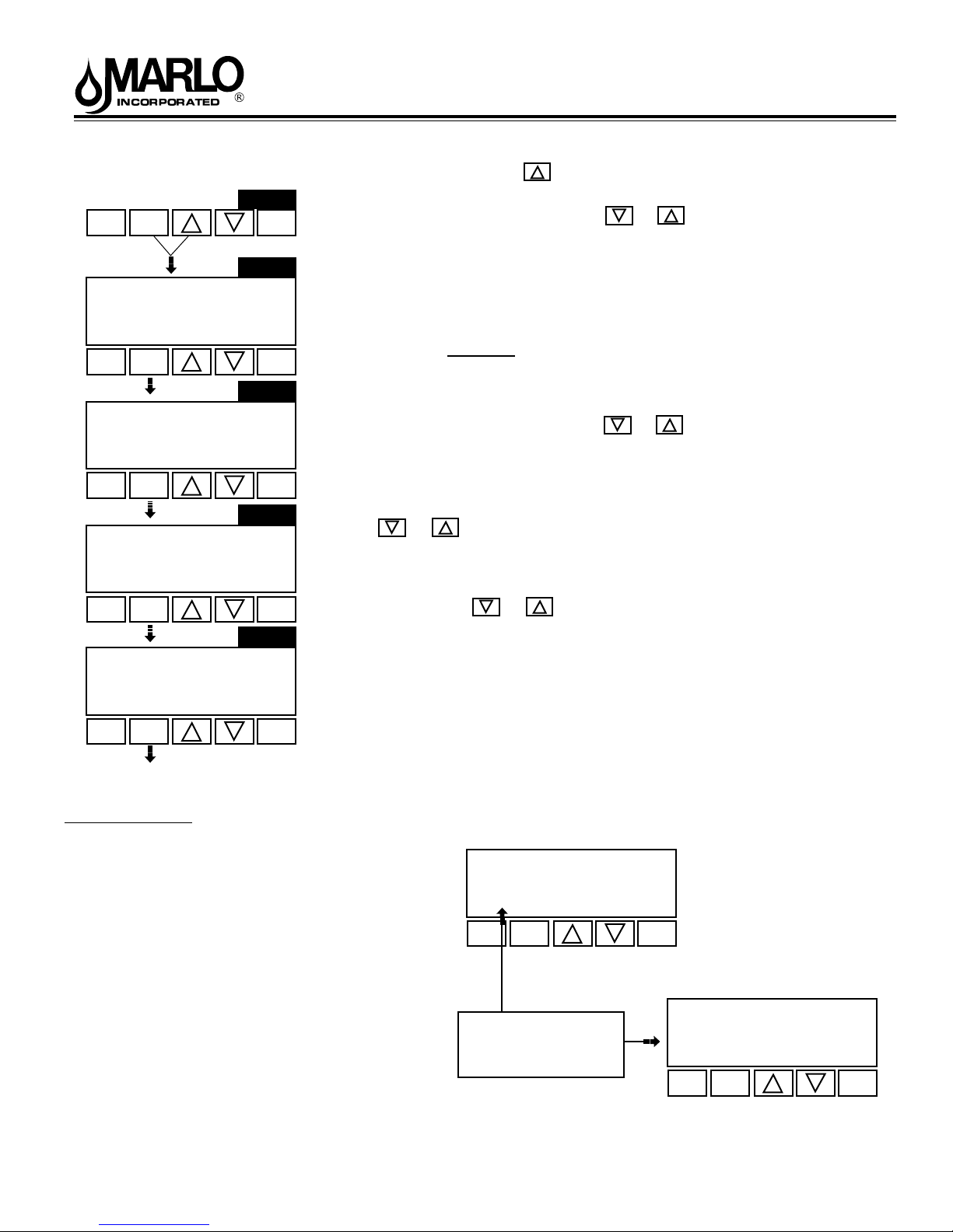
Installer Displays/Settings
STEP 1 - Press NEXT and simultaneously for 3 seconds.
STEP 2 - Hardness: Set the amount of hardness in grains of hardness as
calcium carbonate per gallon using the or buttons. Value ranges from
1 to 150 in 1 grain increments. Note the grains per gallon can be increased if
soluble iron needs to be reduced. This display will show
“-nA-” if “FILTER” is selected or if ‘AUTO’ is not selected. Press NEXT to go to
step 3. Press REGEN to exit Installer Displays/Settings.
STEP 3 - Day Override: When gallon capacity is set to off, set the number
of days between regenerations. When gallon capacity is set to AUTO or to a
number, set the maximum number of days between regenerations. If value set
to “oFF” regeneration initiation is based solely on gallons used. If value is set as
a number (allowable range from 1 to 28) a regeneration initiation will be called
for on that day even if sufcient number of gallons were not used to call for a
regeneration. Set Day Override using or buttons:
• number of days between regeneration (1 to 28); or
• “oFF”
Press NEXT to go to step 4. Press REGEN to return to previous step.
STEP 4 - Next Regeneration Time (hour): Set the hour of day for regeneration
using or buttons. AM/PM toggles after 12. The default time is 2:00
a.m. This display will show “REGEN on 0 GAL” if “on 0” is selected in by the
installer. Press NEXT to go to Step 5. Press REGEN to return to previous step.
STEP 5 - Next Regeneration Time (minutes): Set the minutes of day for
regeneration using or buttons. This display will not be shown if “on
0” is selected by the installer (2 a.m. is the factory setting). Press NEXT to exit
Installer Displays/Settings. Press REGEN to return to previous step.
To initiate a manual regeneration immediately, press and hold the “REGEN”
button for three seconds. The system will begin to regenerate immediately.
The control valve may be stepped through the various regeneration cycles by
pressing the “REGEN” button.
RETURN TO
NORMAL MODE
General Operation
When the system is operating one of two displays will
be shown. Pressing NEXT will alternate between the
displays. One of the displays is always the current time
of day which has to be set (see pg.9). Capacity
remaining is the number of gallons that will be treated
before the system goes through a regeneration cycle.
The user can scroll between the displays as desired.
If the system has called for a regeneration that will occur
at the preset time of regeneration, the words REGEN
TODAY will appear on the display.
When water is being treated (i.e. water is owing through
the system) the word “Softening” or “Filtering” ashes on
the display.
User Displays/Settings
SOFTENING
REGEN
TODAY
SET
CLOCK
NEXT
CAPACITY REMAINING
650
REGEN TODAY will
show if a regeneration
is expected “Tonight.”
8
GAL
REGEN
TIME
SOFTENING
REGEN
TODAY
SET
CLOCK
6:35
NEXT
PM
REGEN
8-171 R5
Page 9
“CMP” & “C” Series Automatic Water Conditioners
Regeneration Mode
Typically a system is set to regenerate at a time of low water usage. An example of a
time with low water usage is when a household is asleep. If there is a demand for water
when the system is regenerating, untreated water will be used.
When the system begins to regenerate, the display will change to include information about the step of the regeneration
process and the time remaining for that step to be completed. The system runs through the steps automatically and will
reset itself to provide treated water when the regeneration has been completed.
Manual Regeneration
Sometimes there is a need to regenerate the system,
sooner than when the system calls for it, usually referred to
as manual regeneration. There may be a period of heavy
water usage because of guests or a heavy laundry day.
To initiate a manual regeneration at the preset delayed regeneration time, press and release “REGEN”. The words
“REGEN TODAY” will ash on the display to indicate that the system will regenerate at the preset delayed regeneration time. If you pressed the “REGEN” button in error, pressing the button again will cancel the request. Note: If the
regeneration time option is set to “on 0” there is no set delayed regeneration time so “REGEN TODAY” will not activate
if “REGEN” button is pressed.
To initiate a manual regeneration immediately, press and hold the “REGEN” button for three seconds. The system will
begin to regenerate immediately. The request cannot be cancelled.
Note: For softeners, if brine tank does not contain salt, ll with salt and wait at least two hours before regenerating.
SET
CLOCK
SET TIME
SET
CLOCK
SET TIME
Step 1U
NEXT
Step 2U
6:35
NEXT
Step 3U
Set Time of Day
REGEN
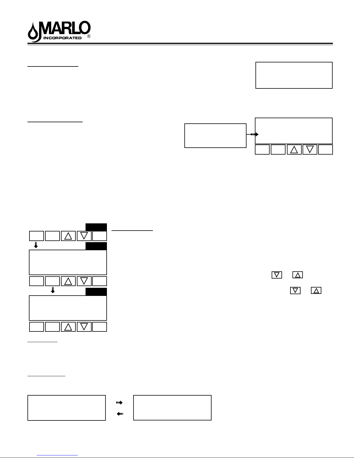
The user can also set the time of day. Time of day should only need to be set after
extended power outages or when daylight saving time begins or ends and at the time
of start-up. If an extended power outage occurs, the time of day will ash on and off
P.M.
which indicates the time of day should be reset.
STEP 1U - press SET CLOCK.
STEP 2U - Current Time (hour): Set the hour of the day using or buttons.
REGEN
AM/PM toggles after 12. Press NEXT to go to step 3U.
STEP 3U - Current Time (minutes): Set the minutes of the day using or
buttons. Press NEXT to exit Set Clock. Press REGEN to return to previous step.
P.M.
REGEN TODAY will
show if a regeneration
is expected “Tonight.”
REGEN
2 8:22
BACKWASH
REGEN
TODAY
SET
CLOCK
NEXT
CAPACITY REMAINING
GAL
320
REGEN
6:35
SET
NEXT
CLOCK
Power Loss
If the power goes out for less than two hours, the system will automatically reset itself. If an extended power outage
occurs, the time of day will ash on and off which indicates the time of day should be reset. The system will retain the
other information entered by the installer.
Error Message
If the word “ERROR” and a number are alternately ashing on the display contact the Installer for help. This indicates
that the valve was not able to function properly. Refer to “Troubleshooting” for “ERROR RESET” procedure.
REGEN
Error
1003
9
8-171 R5
Page 10
“CMP” & “C” Series Automatic Water Conditioners
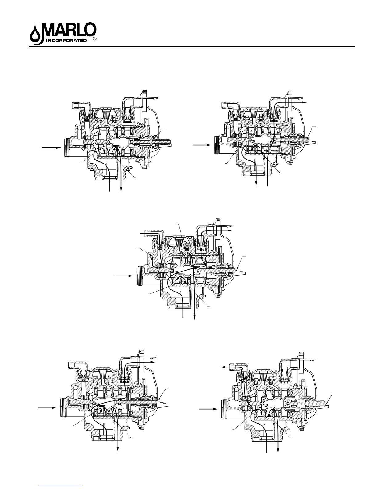
FLOW DIAGRAMS
SUPPLY
WATER
ow diagram...service
OUTLET PORT FOR
SERVICE WATER
SUPPLY
WATER
INLET
CONDITIONED WATER
FROM DISTRIBUTOR
SUPPLY WATER TO
TOP OF TANK
ow diagram...downow brine
REGENERANT IN
REGENERANT
IS SIPHONED IN
REGENERANT TRAVELS
THROUGH MANIFOLD
TO THE INJECTOR
PISTON ROD IS BOTTOMED
OUT IN “HOME” POSITION
SUPPLY
WATER
MANIFOLD
ow diagram...backwash
TO DRAIN
OUTLET PORT FOR
SERVICE WATER
SUPPLY WATER
INLET
SUPPLY WATER
TO DISTRIBUTOR
TO DRAIN
PISTON ROD IS
BELOW 3rd STEP DOWN
BACKWASH WATER
TO DRAIN
PISTON ROD IS
BELOW 2nd STEP DOWN
SUPPLY
WATER
SUPPLY
WATER
OUTLET PORT FOR
SERVICE WATER
ow diagram...rinse
OUTLET PORT FOR
SERVICE WATER
CONDITIONED WATER
FROM DISTRIBUTOR
SUPPLY WATER
INLET
SUPPLY WATER TO
TOP OF TANK
WASTE WATER
FROM DISTRIBUTOR
TO DRAIN
CONDITIONED WATER
TO REGENERANT TANK
PISTON ROD IS
4th STEP DOWN
SUPPLY
WATER
SUPPLY WATER
INLET
SUPPLY WATER AND REGENERANT
TO TOP OF TANK
ow diagram...ll
OUTLET PORT FOR
SERVICE WATER
CONDITIONED WATER
FROM DISTRIBUTOR
10
SUPPLY WATER
INLET
SUPPLY WATER TO
TOP OF TANK
PISTON ROD IS
BELOW 1st STEP DOWN
8-558 R1
Page 11
“CMP” & “C” Series Automatic Water Conditioners
Bypass Valve
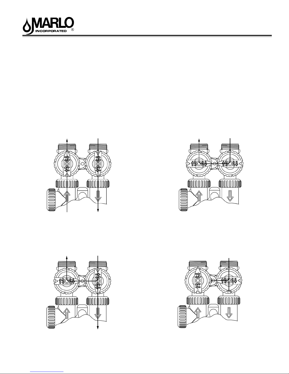
The bypass valve is typically used to isolate the control valve from the plumbing system’s water pressure in order to perform control valve repairs or maintenance. The WS1 bypass valve is particularly unique in the water treatment
industry due to its versatility and state of the art design features. The 1” full ow bypass valve incorporates four positions
including a diagnostic position that allows service personal to work on a pressurized system while still providing untreated
bypass water to the facility or residence. Its completely non-metallic, all plastic, design allows for easy
access and serviceability without the need for tools.
The bypass body and rotors are glass lled Noryl and the nuts and caps are glass lled polypropylene. All seals are
self-lubricating EPDM to help prevent valve seizing after long periods of non-use. Internal o-rings can easily be replaced
if service is required.
The bypass consists of two interchangeable plug valves that are operated independently by red arrow shaped handles.
The handles identify the ow direction of the water. The plug valves enable the bypass valve to operate in four positions.
Figure 1
NORMAL OPERATION
“Treated”
Water Exits
Supply
Water Enters
BYPASS OPERATION
“Untreated”
Water Exits
Figure 2
Supply
Water Enters
Normal Operation:
The inlet and outlet handles point in the direction of ow indicated by
the engraved arrows on the control valve. Water ows through the
control valve during normal operation and this position also allows the
control valve to isolate the media bed during the regeneration cycle.
Figure 3
DIAGNOSTIC MODE
Supply
Water Exits
Diagnostic:
The inlet handle points in the direction of ow and the outlet handle
points to the center of bypass valve, system water pressure is allowed
to the control valve and the plumbing system while not allowing water to
exit from the control valve to the plumbing.
Supply
Water Enters
Bypass:
The inlet and outlet handles point to the center of the bypass, the control
valve is isolated from the water pressure contained in the plumbing
system. Untreated water is supplied to the plumbing system.
Figure 4
SHUT OFF MODE
No
Water Exits
Shut Off:
The inlet handle points to the center of the bypass valve and the outlet
handle points in the direction of ow, the water is shut off to the plumbing
system. If water is available on the outlet side of the softener it is an
indication of water bypass around the system (i.e. a plumbing
connection somewhere in the building bypasses the system).
11
Supply Water is shut off
from the house and the
valve
8-171 R5
Page 12
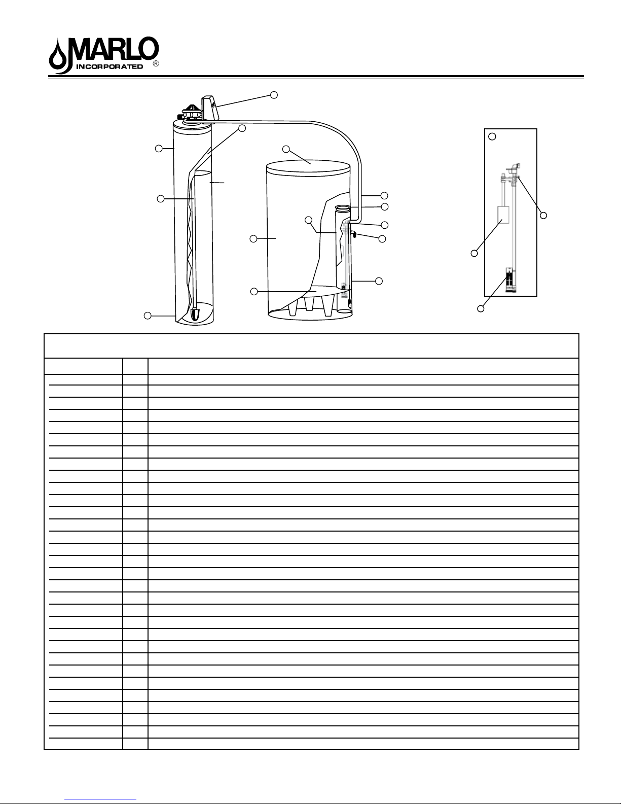
“C” Series
Media Tank Jacket
w/ Cover
“CMP” & “C” Series Automatic Water Conditioners
1
Valve (Metered Shown)
Media Tank
10
12
Brine Tank Cover
2
Brine
13
Valve
Assembly
Distributor Tube
w/ Screen
Media Tank
Base
11
10
Media
Brine Tank
Brine Grid
(Optional)
2
15
Brine Well
Brine Line Hosing
7
Brine Well Caps
4
3
Brine Valve Safety
8
Overflow Drain
5
Brine Tube
6
w/ Air Check
Brine Float
9
6
Brine Tube w/
Air Check
Parts Listing
Part Number No. Description
Contact Factory 1 Valve Metered (Complete - Specify Model)
B1209053 2 Brine Tank w/ Cover (Complete for CMP-22K, C-22-2 w/ grid)
A2042065 2 Brine Tank w/ Cover (Complete w/ Grid for CMP-30K, 40K, 45K, CMP25 Combo, CMP45 Combo)
A2042064 2 Brine Tank w/ Cover (Complete for w/ Grid for CMP-60K, C-60-2)
A2042061 2 Brine Tank w/ Cover (Complete for CMP-22K, 30K, 40K, 45K, C-22-2, C-40-2, C-30-2, C-45-2, C-60-2)
B1210033 2 Brine Tank w/ Cover (Complete for CMP-60K)
A2071005 3 Brine Well
A2072003 4 Brine Well Cap
A2250003 5 Overow Elbow
A2118010 6 Brine Tube w/ Air Check
B1227002 7 Brine Line Hose w/ Inserts
A2005058 8 Brine Valve Safety
A2107022 9 Brine Float
A2126201 10 8 x 44 Media Tank - w/ Base CMP-22K C-22-2
A2126203 10 9 x 48 Media Tank - w/ Base CMP-30K C-30-2
A2126206 10 10 x 54 Media Tank - w/ Base CMP-45K C-45-2
A2126208 10 12 x 52 Media Tank - w/ Base CMP-60K C-60-2
A2126205 10 10 x 47 Media Tank - w/ Base CMP-25 Combo & (CMP-40K & C-40-2 if built after 06/01/04)
Contact Factory -- Media (Specify Model)
B1023056 11 Distributor Tube Assembly - Specify Model
B1229004 11 Distributor Tube Assembly - for CMP-25 Combo
B1024006 12 Media Tank Jacket C-22-2 CMP-22K 8” Dia., Almond
B1024009 12 Media Tank Jacket w/ cover C-30-2 & C-40-2 CMP-30K & CMP-40K 9” Dia., Almond
B1024015 12 Media Tank Jacket w/ cover C-40-2 & C-45-2 CMP-45K & CMP-45K 10” Dia., Almond
B1024018 12 Media Tank Jacket w/ cover C-60-2 CMP-60K 12” Dia., Almond
B1024015 12 Media Tank Jacket CMP-25 Combo & (CMP-40K & C-40-2 if built after 06/01/04)
B1180011 13 * Brine Valve Assembly - Complete - Includes #’s 6, 8, & 9
A2354023 14 *1” Bypass - Does not include tting kit (Not Shown)
A2284002 15 *Grid Set-All (Optional)
A2121013 16 Media Resin (must also purchase A21220080 garnet [30#].) (used only on CMP-25 Combo model)
A2122008D 17 Garnet [30#] (used only on CMP-25 Combo model)
12
8
Brine
Valve
Safety
8-171 R5
Page 13
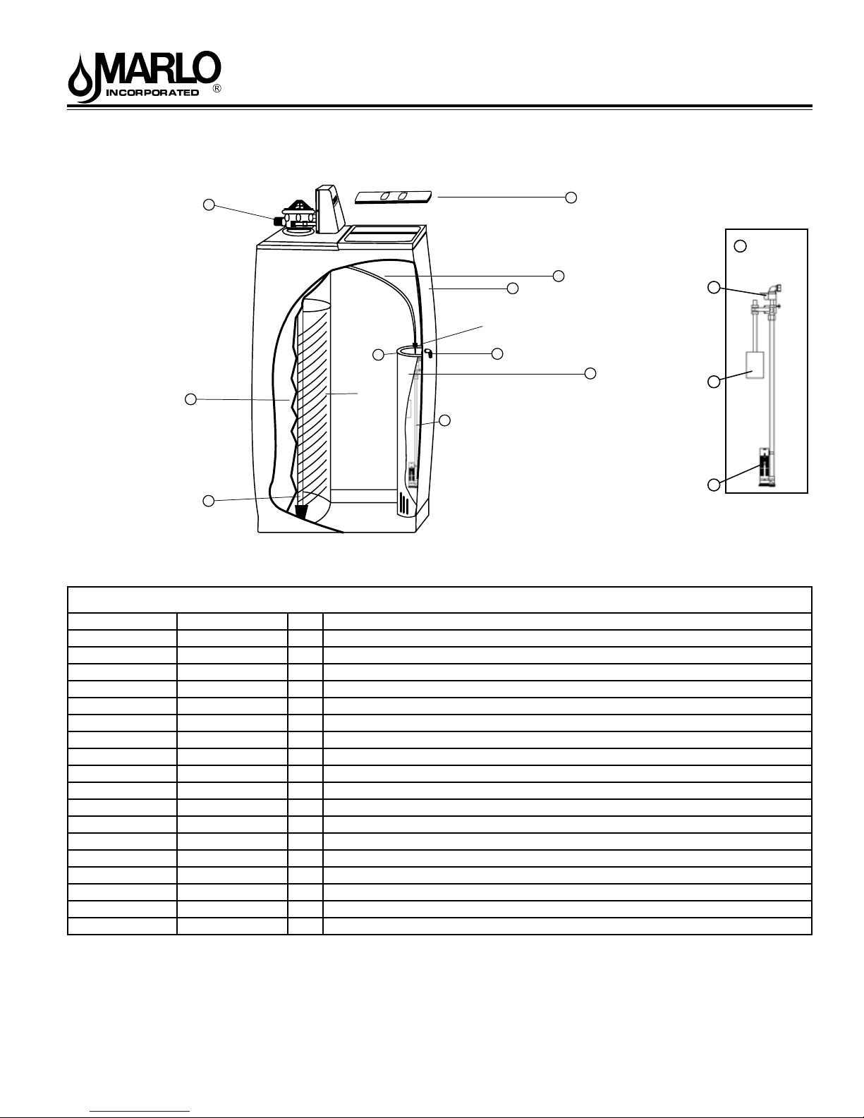
“C” Series
1
Valve
(Does not include
Bypass)
Media Tank
Distributor Tube w/
Distributor Screen
11
“CMP” & “C” Series Automatic Water Conditioners
Lo Pro Cover
2
Salt Port Cover
Brine
12
Valve
Assembly
9
10
8
Brine Well
Cover
5
Media
Drain Line Elbow
Overflow Elbow
6
Brine Tube with Air
8
Check
Cabinet
3
Brine Line Hose
7
Brine Well
4
Brine
Valve
Safety
Brine Float
Brine Tube w/
Air Check
Parts Listing
Part Number Control Number No. Description
Contact Factory 1 Valve Metered (Complete - Specify Model)
A2103030 2 Lo Pro Cover
A2274004 3 Cabinet w/ cover
A2071005 4 Brine Well
A2072003 5 Brine Well Cap
B1227002 6 Overow Elbow
B1227003 7 Brine Line Hose w/ inserts
A2118010 8 Brine Tube w/ air check
A2005058 9 Brine Valve Safety
A2107023 10 Brine Float
A2255101 11 9 x 35 Media Tank w/o Base CMP-22KC C-22-C
A2255102 11 10 x 35 Media Tank w/o Base CMP-30KC C-30-C
Contact Factory -- Media (Specify Model)
B1023050 -- Distributor Tube W/Distributor Screen (All)
B1180011 12 Brine Valve Assembly - Complete - includes #’s 8, 9, & 10
A2355023 13 *1” Bypass Does not include tting kit (Not Shown)
B1021009 -- *Grid Set(Optional-Not Shown) CMP-30-KC C-30-C
B1021010 -- *Grid Set(Optional-Not Shown) CMP-22-KC C-30-C
13
8-171 R5
Page 14
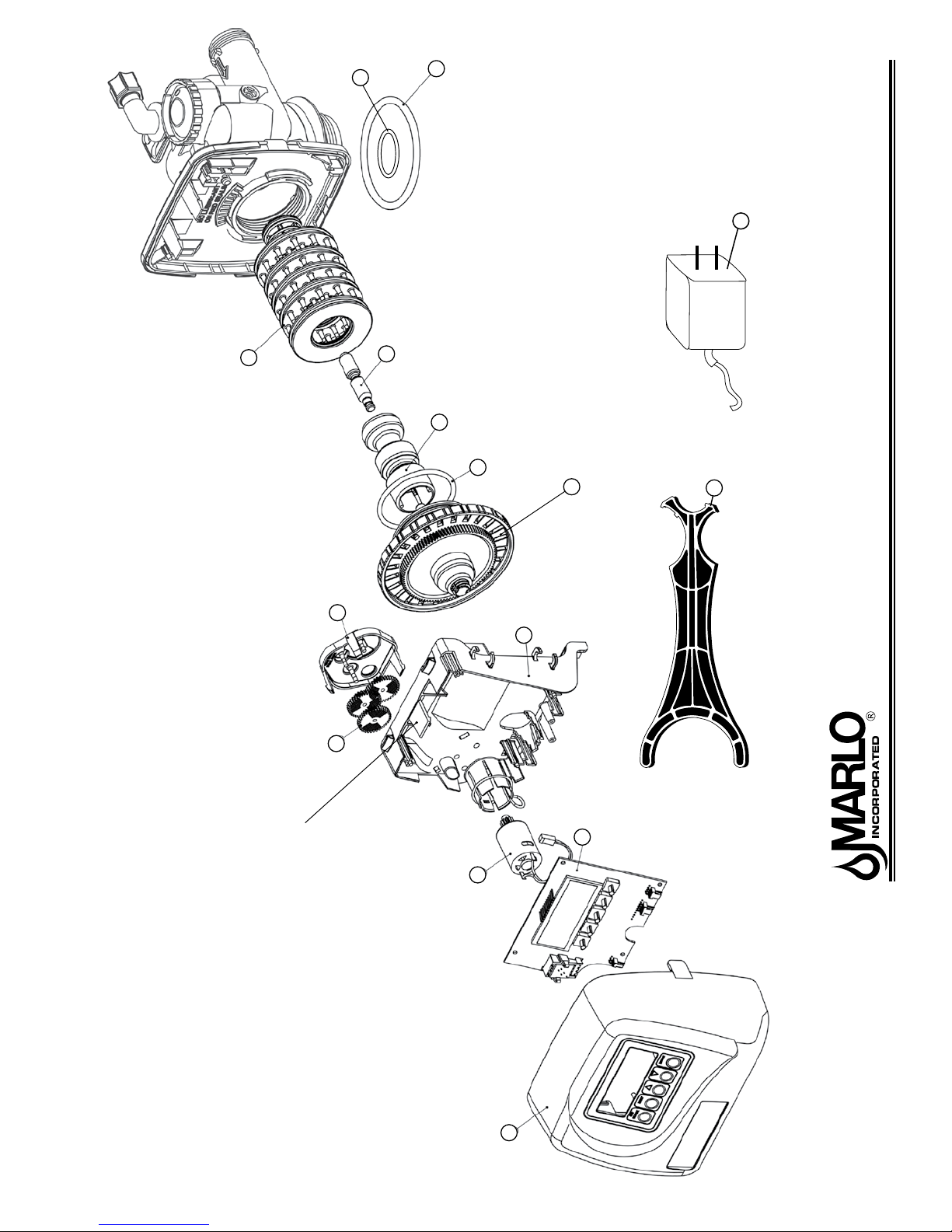
t
15
1
5
t
6
Not used on
“Backwash Only”
Type Filters
4
14
O-rings on Spacer Stack
not available separately
12
11
t
3
9
Turn counter-clockwise to remove.
Turn clockwise to install.
2
13
Service Tool
(Optional)
Part of Kit, O-ring (Item #51)
t
“CMP” & “C” Series Automatic Water Conditioners
10
8
Lift tab to remove item 10
Drive Cap Assembly, Downow Piston,
Regenerant Piston and Spacer Stack Assembly
& Front Cover and Drive Assembly
7
8-171 R5
14
Page 15
“CMP” & “C” Series Automatic Water Conditioners
Drive Cap Assembly, Downow Piston, Upow Piston,
Regenerant Piston and Spacer Stack Assembly
Item No. Part No. Description Quantity
1 A2466034 *Spacer Stack Assembly w/o o-rings 1
2 A2080077 Drive Cap Assembly 1
3 use item 16 O-Ring 228 (use Valve O-ring Kit) 1
t
4 A2309040 Piston Downow Assembly 1
p
5 A2438033 Regenerant Piston 1
V
6 use item 51 O-Ring 337 (use Valve O-ring Kit) 1
t
use item 51
15
t
Item #4 identied with “DN” code.
p
Item #5 not used with Backwash Only lter applications.
V
See page 20 for Valve O-ring Kit.
t
O-Ring 215
Front Cover and Drive Assembly
Item No. Part No. Description Quantity
7 A2103133 Front Cover ASSY 1
8 A2085050 Motor 1
9 A2328046 Drive Bracket & Spring Clip 1
10 A2341012 PC Board 1
11 A2393046 Drive Gear 12 x 36 3
12 A2103132 Drive Gear Cover 1
13 A2491086 Service Tool 1
14 A2242054 Transformer 110V - 12V 1
(use Valve O-ring Kit)
1
15
8-171 R5
Page 16
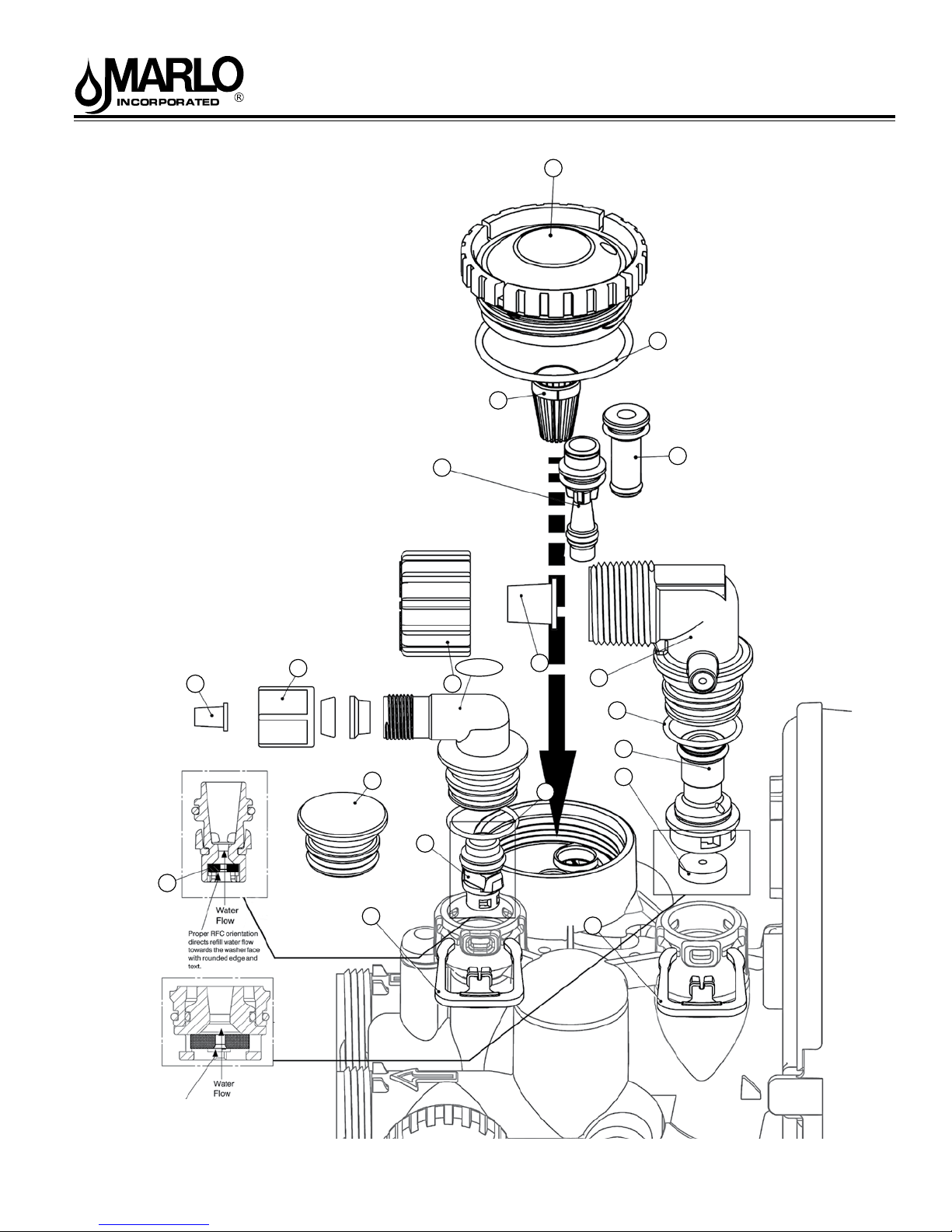
“CMP” & “C” Series Automatic Water Conditioners
Injector Cap, Injector Screen, Injector, Plug ,
O-Ring, Rell and Rell Port Plug,
&Drain Line - 3/4”
Part of Kit, O-ring (Item #51, pg. 20)
t
18
16
17
28
23
24
21
27
20
31
25a, 25b
19
30
32
33
34
35
26
Proper ow washer orientation
directs water ow towards the
washer face with rounded edge.
Flow washer indentication
numbers must be visible after
installation.
22
16
29
8-171 R5
Page 17
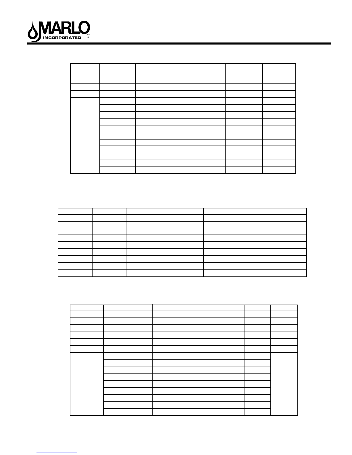
“CMP” & “C” Series Automatic Water Conditioners
Injector Cap, Injector Screen, Injector, Plug and O-Ring
Item No. Part No. Description Quantity
16 A2080079 Injector Cap 1
17 Use Item 51 O-Ring 135
t
18 A2142016 Injector Screen 1
19 A2079059 Injector Assembly Z Plug See note 1
A2079060 Injector Assembly A Black
A2079048 Injector Assembly B Brown
A2079046 Injector Assembly C Violet
A2079045 Injector Assembly D Red
20 A2079049 Injector Assembly E White
A2079047 Injector Assembly F Blue
A2079050 Injector Assembly G Yellow
A2079055 Injector Assembly H Green
A2079062 Injector Assembly I Orange
A2079063 Injector Assembly J Light Blue
A2079064 Injector Assembly K Light Green
*The injector plug and the injector each contain one 011 (lower) and 013 (upper) o-ring.
Note: For downow brine, injector is located in the down hole and injector plug in the up hole.
For a lter that only backwashes injector plugs are located in both holes.
Rell and Rell Port Plug
Drawing No. Order No. Description Quantity
21 A2287059 Rell Port Plug Assembly This part is required for backwash only systems
22 A2411015 Elbow Locking Clip 1
23 A2409016 Polytube insert 3/8 1
24 A2095071 Nut 3/8 1
25a A2080078 Elbow Cap 3/8 (use w/ 3/8” tubing) 1
25b A2129100 Elbow 1/2” with nut and insert (use w/ 1/2” tubing) Option
26 Use Item 51 O-Ring 019
t
27 A2104033 RFC Retainer Assembly* 1
28 A2253108 RFC Brine Rell Flow Washer 1
*Assembly includes RFC.
(Use Valve O-ring Kit) 1
(
Use Valve O-ring Kit
)
1
1
Drawing No. Order No. Description Quantity
29 A2411015 Elbow Locking Clip 1
30 A2409013 Polytube insert 5/8 Option
31 A2095065 Nut 3/4 Drain Elbow Option
32 A2099056 Drain Elbow 3/4 Male Assembly 1
33 Use Item 51 O-Ring 019
t
34 A2104034 Drain Flow Washer Retainer Assembly 1
A2253114 Drain Flow Washer 0.7 gpm for 3/4
A2253099 Drain Flow Washer 1.0 gpm for 3/4
A2253084 Drain Flow Washer 1.3 gpm for 3/4
A2253083 Drain Flow Washer 1.7 gpm for 3/4
35
A2253081 Drain Flow Washer 2.2 gpm for 3/4
A2253082 Drain Flow Washer 2.7 gpm for 3/4
A2253085 Drain Flow Washer 3.2 gpm for 3/4
A2253086 Drain Flow Washer 4.2 gpm for 3/4
A2253087 Drain Flow Washer 5.3 gpm for 3/4
Drain Line - 3/4”
(Use Valve O-ring Kit) 1
One
DLFC
must be
used if 3/4
tting is
used
8-171 R5
17
Page 18
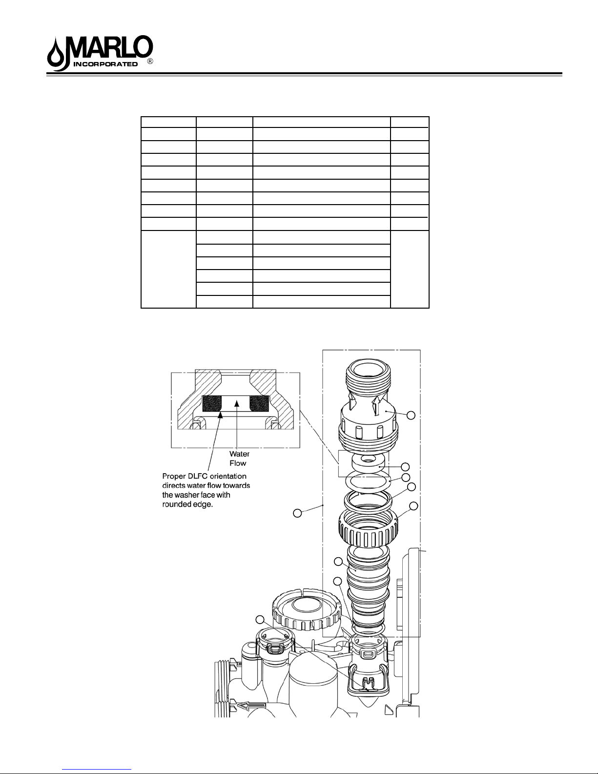
“CMP” & “C” Series Automatic Water Conditioners
Drain Line - 1”
Drawing No. Order No. Description Quantity
1 A2411015 Elbow Locking Clip 1
2 A2099072 Drain FTG 1” Straight 1
3* A2005075 Drain FTG Body 1” 1
4* A2097040 Drain FTGAdapter 1” 1
5* A2077179 O-Ring 019 1
6* A2453012 Split Ring 1
7* A2095069 Nut 1” Quick Connect 1
8* A2077178 O-Ring 215 1
A2253117 DLFC 9.0 gpm for 1
A2253118 DLFC 11.0 gpm for 1
A2253119 DLFC 13.0 gpm for 1
A2253120 DLFC 17.0 gpm for 1
9
A2253121 DLFC 20.0 gpm for 1
A2253122 DLFC 25.0 gpm for 1
*Can be ordered as a set order number A2099072, description: Drain FTG 1 Straight.
One
DLFC
must be
used if 1
tting is
used
3
9
8
6
2
4
5
1
7
18
8-171 R5
Page 19
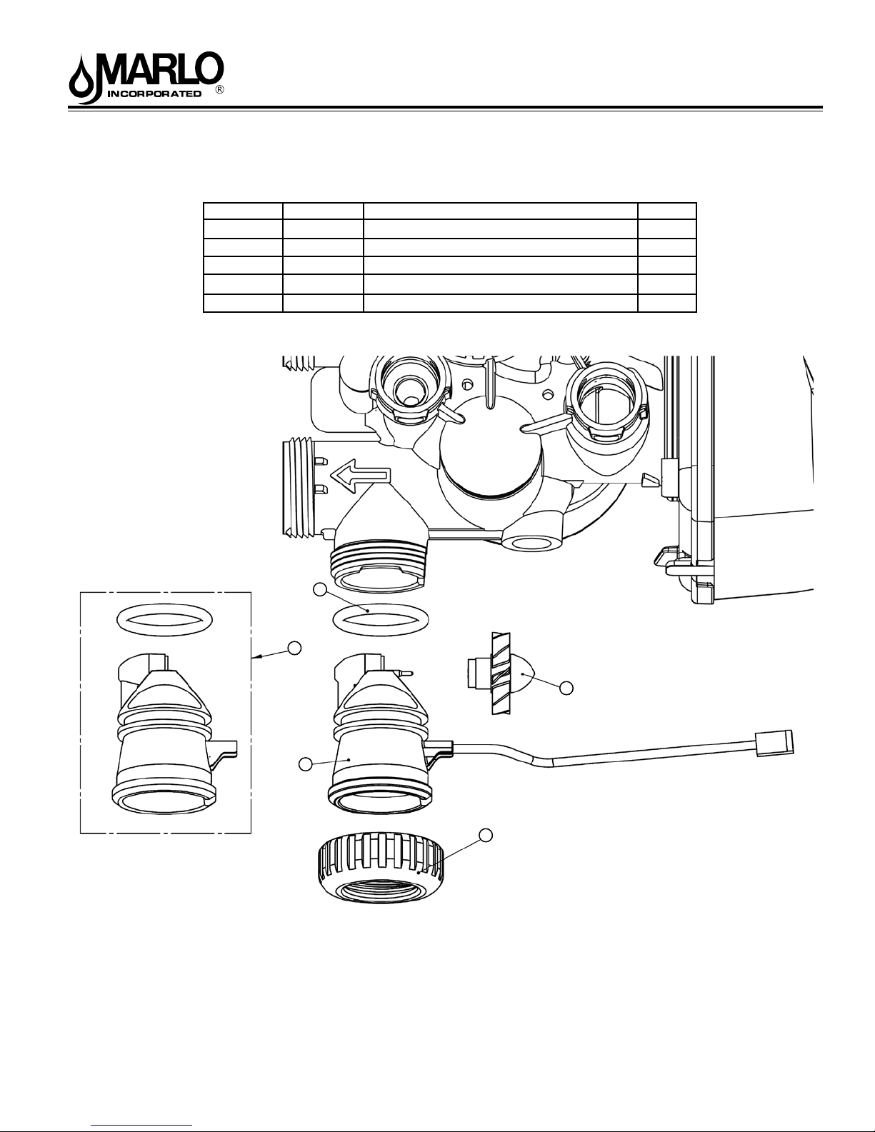
“CMP” & “C” Series Automatic Water Conditioners
Water Meter and Meter Plug
Item No. Part No. Description Quantity
36 A2095069 Nut 1” Quick Connect 1
*37 A2360039 Meter Assembly 1
38 A2100027 Turbine Assembly 1
39 use item 51 O-Ring 215 (Use Valve O-ring Kit) 1
40 A2287077 Meter Plug Assembly (Time clock option) 1
*Item #37 includes Items #38 & #39.
t
Part of Kit, O-ring (Item 51, pg. 20)
t
39
40
38
37
36
19
8-171 R5
Page 20
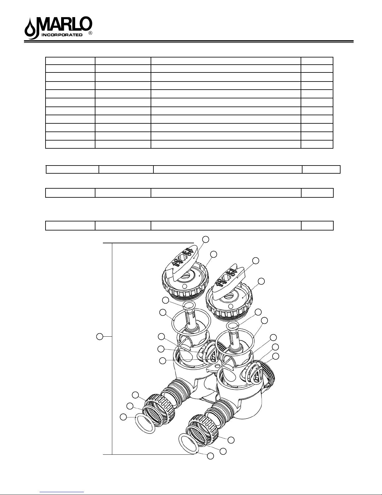
“CMP” & “C” Series Automatic Water Conditioners
Item No. Part No. Description Quantity
41 A2095069 Nut 1” Quick Connect 2
42 A2453012 Split Ring 2
l
43 use item 52 O-Ring 215 (Kit available - see Item #10) 2
44 A2607004 Bypass 1” Rotor 2
45 A2080090 Bypass Cap 2
46 A2395009 Bypass Handle 2
47 A2104036 Bypass Rotor Seal Retainer 2
l
48 use item 52 O-Ring 135 (use Bypass Valve Kit) 2
l
49 use item 52 O-Ring 112 (use Bypass Valve Kit) 2
l
50 use item 52 O-Ring 214 (use Bypass Valve Kit) 2
l
Part of Kit, O-ring By-Pass(Item 52)
Valve O-ring Kit
s
51 B1213022 KIT O-ring (contains 1 each of 3, 6, 15, 17, 26, & 33) 1 per valve
Bypass Valve O-ring Kit
52 B1213021 KIT O-ring Bypass (Incl. 2 ea. of items 43,48,49,& 50) 1 per valve
(Not Shown) Order No. A2412076, Description Bypass Vertical Adapter Assembly
l
Complete Assembly
53 A23540231 Bypass Valve Complete / Less Connectors 1 per valve
46
45
46
5
49
l
l
48
l
53
41
44
50
l
47
49
48
l
44
50
l
47
42
43
l
20
41
42
43
l
8-171 R5
Page 21
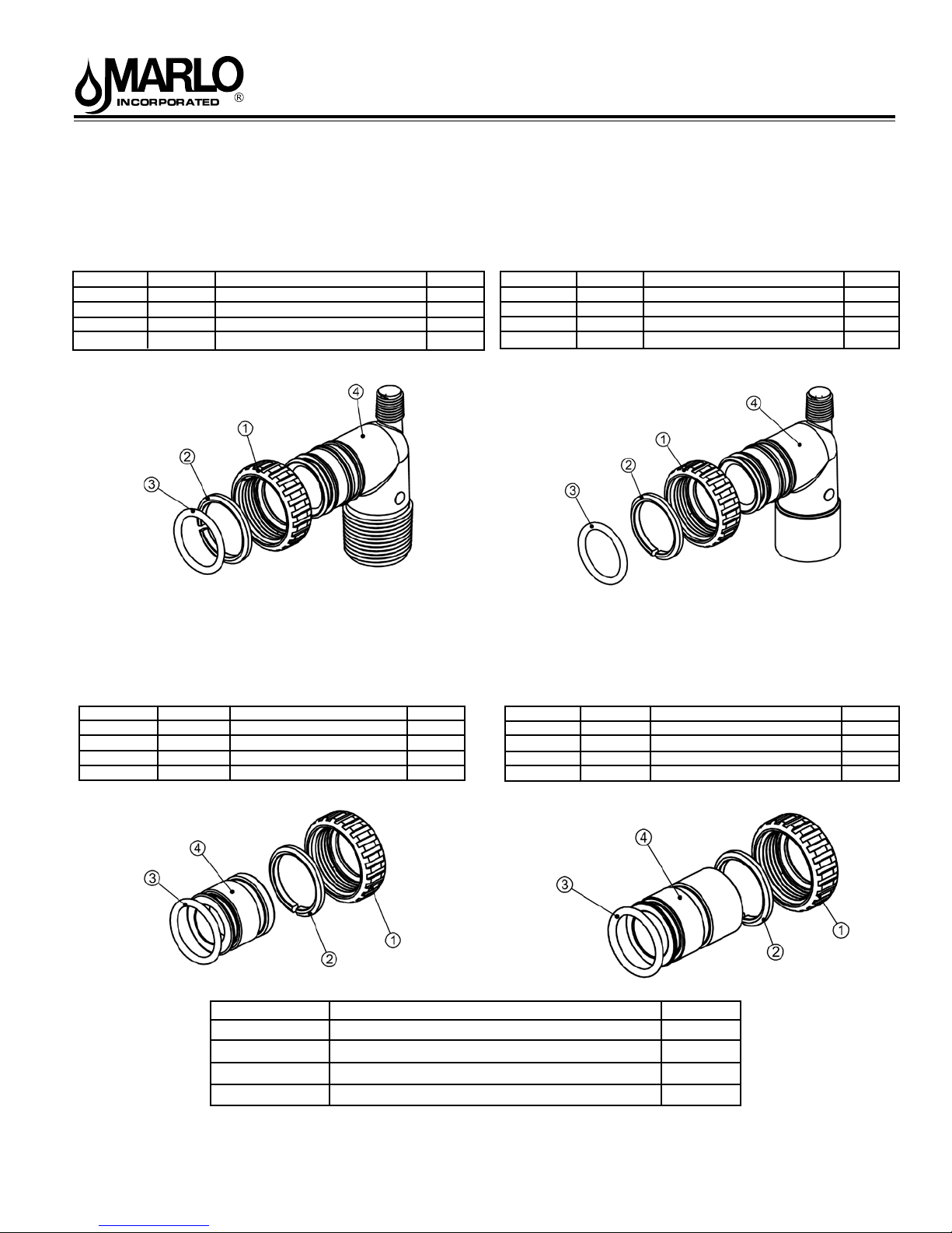
“CMP” & “C” Series Automatic Water Conditioners
Description: Fitting 1” PVC Male NPT Elbow Assembly
Order No: A2129080 (Optional)
Drawing No. Order No. Description Quantity
1 A2095069 Nut 1” Quick Connect 2
2 A2453012 Split Ring 2
3 A2077178 O-Ring 215 2
4 A2129101 Fitting 1”PVCMaleNPT Elbow 2
Order No: A2435068 (Standard)
Description: Fitting 1” Brass Sweat Assembly
Order No: A2099054 (Optional)
Description: Fitting 3/4” & 1” PVC Solvent 900 Asy
Drawing No. Order No. Description Quantity
1 A2095069 Nut 1” Quick Connect 2
2 A2453012 Split Ring 2
3 A2077178 O-Ring 215 2
4 A2569008 Fitting 3/4&1 PVC Solvent 90 2
Order No: A2435072 (Optional)
Description: Fitting 3/4” Brass Sweat Assembly
Drawing No. Order No. Description Quantity
1 A2095069 Nut 1” Quick Connect 2
2 A2453012 Split Ring 2
3 A2077178 O-Ring 215 2
4 A2569006 Fitting 1” Brass Sweat 2
Part No. Description Quantity
A2095069 Nut 1” Quick Connect 2
A2453012 Split Ring 2
A2077178 O-Ring 215 2
A2412076 Bypass Vertical Adapter Assembly 2
Drawing No. Order No. Description Quantity
1 A2095069 Nut 1” Quick Connect 2
2 A2453012 Split Ring 2
3 A2077178 O-Ring 215 2
4 A2569007 Fitting 3/4” Brass Sweat 2
21
8-171 R5
Page 22
“CMP” & “C” Series Automatic Water Conditioners
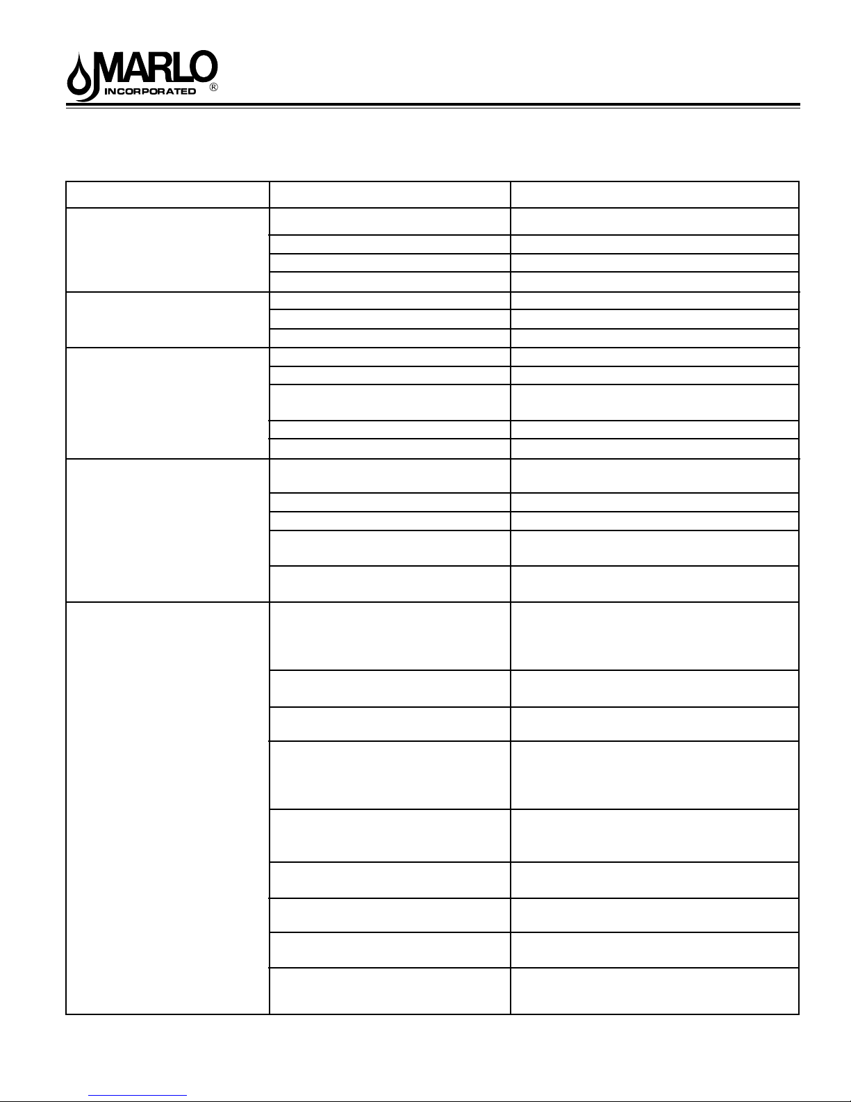
Table 15
Troubleshooting Procedures
Problem Possible Cause Solution
1. Timer does not display
time of day
2. Timer does not display
correct time of day
3. No softening/ltering
display when water is
owing
4. Control valve regenerates
at wrong time of day
5.ERROR followed by
code number
1001 Error Code -
Unable to recognize start
of regeneration
1002 Error Code Unexpected stall
1003 Error Code -
Motor ran to long, timed
out trying to reach next
cycle position
1004 Error Code -
Motor ran to long, timed out
trying to reach home
position
If other Error Codes display
contact the factory
ERROR Reset Procedure:
1. Correct error condition.
2. Press NEXT and
REGEN simultaneously
for three seconds.
a. Transformer unplugged
b. No electric power at outlet
c. Defective transformer
d. Defective PC board
a. Switched outlet
b. Power outage
c. Defective PC board
a. Bypass valve in bypass position
b. Meter connection disconnected
c. Restricted/stalled meter turbine
d. Defective meter
e. Defective PC board
a. Power outages
b. Time of day not set correctly
c. Time of regeneration incorrect
d. Control valve set at “on 0”
(immediate regeneration)
e. Control valve set at NORMAL +
on 0
a. Control valve has just been ser-
viced
b. Foreign matter is lodged in control
valve
c. High drive forces on piston
d. Control valve piston not in home
position
e. Motor not inserted fully to engage
pinion, motor wires broken or
disconnected, motor failure
f. Drive gear label dirty or damaged,
missing or broken gear
g. Drive bracket incorrectly aligned
to back plate
h. PC board is damaged or defective
i. PC board incorrectly aligned to
drive bracket
a. Connect power
b. Repair outlet or use working outlet
c. Replace transformer
d. Replace PC board
a. Use uninterrupted outlet
b. Reset time of day
c. Replace PC board
a. Put bypass valve in service position
b. Connect meter to PC board
c. Remove meter and check for rotation
or foreign material
d. Replace meter
e. Replace PC board
a. Reset control valve to correct time of
day
b. Reset to correct time of day (a.m./p.m.)
c. Reset regeneration time (a.m./p.m.)
d. Check control valve set-up procedure
regeneration time option
e. Check control. valve set-up procedure
regeneration time option
a. Press NEXT and REGEN for 3
seconds or unplug power source jack
(black wire) and plug back in to reset
control valve
b. Check piston and spacer stack as-
sembly for foreign matter
c. Replace piston(s) and spacer stack
assembly
d. Press NEXT and REGEN for 3
seconds or unplug power source jack
(black wire) and plug back in to reset
control valve
e. Check motor and wiring. Replace
motor if necessary
f. Replace or clean drive gear(s)
g. Reseat drive bracket properly
h. Replace PC board
i. Ensure PC board is correctly snapped
on to drive bracket
22
8-171 R5
Page 23
“CMP” & “C” Series Automatic Water Conditioners
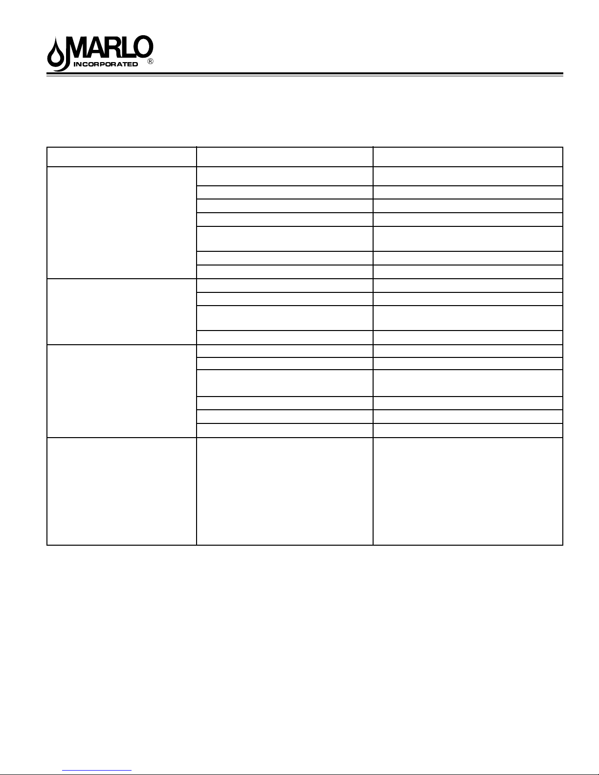
Troubleshooting Procedures
(continued)
Problem Possible Cause Solution
6. Control valve stalled in
regeneration
7. Control valve does not
regenerate automatically
when REGEN button is
depressed and held
8. Control valve does not
regenerate automatically
but does when REGEN
button is depressed
9 Time of day ashes on
and off
a. Motor not operating
b. No electric power at outlet
c. Defective transformer
d. Defective PC board
e. Broken drive gear or drive cap
assembly
f. Broken piston retainer
g. Broken main or regenerant piston
a. Transformer unplugged
b. No electric power at outlet
c. Broken drive gear or drive cap
assembly
d. Defective PC board
a. By-pass valve in bypass position
b. Meter connection disconnected
c. Restricted/stalled meter turbine
d. Defective meter
e. Defective PC board
f. Set-up error
a. Power has been out more than
two hours, the transformer was
unplugged and then plugged
back into the wall outlet, the
transformer plug was unplugged
and then plugged back into the
board or the NEXT and REGEN
buttons were pressed to reset the
valve.
a. Replace motor
b. Repair outlet or use working outlet
c. Replace transformer
d. Replace PC board
e. Replace drive gear or drive cap as-
sembly
f. Replace drive cap assembly
g. Replace main or regenerant piston
a. Connect transformer
b. Repair outlet or use working outlet
c. Replace drive gear or drive cap as-
sembly
d. Replace PC board
a. Put control valve in service position
b. Connect meter to PC board
c. Remove meter and check for rotation
or foreign material
d. Replace meter
e. Replace PC board
f. Check control valve set-up procedure
a.. Reset the time of day
23
8-171 R5
Page 24

NOTES
2227 South Street
P.O. Box 044170
Racine, WI 53404-7003
Ph. (262) 681-1300
Fax (262) 681-1318
www.Marlo-Inc.com
8-171 R5
 Loading...