

Page 1
BLADE MAX MIN. INTAKE
CFM VOL TS WATTS AMPS HP RPM DIA. SHUTTER A TTIC AREA REQUIRED
*1520 120 255 2.6 1/5 1100 16” STD. WOOD 2170 5.1 Sq. Ft.
LOUVER Sq. Ft.
1860 120 250 2.6 1/5 1115 16” METAL 2656 6.2 Sq. Ft.
LOUVER Sq. Ft.
READ AND SAVE THESE INSTRUCTIONS
MODEL GV 16
GABLE MOUNTED
VENTILATOR
READ INSTRUCTIONS CAREFULLY BEFORE ATTEMPTING TO INSTALL, OPERATE OR SERVICE THE
PATTON ATTIC VENTILATOR. FAILURE TO COMPLY WITH INSTRUCTIONS COULD RESULT IN PERSONAL INJURYAND/OR PROPERTY DAMAGE!
RETAIN INSTRUCTIONS FOR FUTURE REFERENCE.
IMPORTANT SAFETY INSTRUCTIONS
WARNING:
TO REDUCE RISK OF FIRE, ELECTRICAL SHOCK OR INJURY
TO PERSONS, OBSERVE THE FOLLOWING:
Description
The Marley Engineered Products gable mounted attic ventilator is
fully automatic and designed for general ventilating use only in the
attic spaces of houses, apartments and other small buildings. Unit
can be installed behind existing attic louvers to exhaust hot air or
pull in cool air. An accessory dehumidistat can be used with this
unit to automatically activate in the winter to help eliminate excessive moisture.
The ventilator comes complete with mounting brackets, 18”
armored flexible cable, prewired automatic thermostat mounted in
junction box, thermally protected motor, and heavy gauge plated
steel housing.
Unpacking
Unpack carefully. Inspect for loose, missing or damaged parts. In
the event of missing components or hidden damage, immediately
contact your distributor or the delivering carrier concerning discrepancies. The motor/fan assembly has been carefully factorybalanced. Care should be taken when handling to avoid damage
resulting in unnecessary vibration and noise.
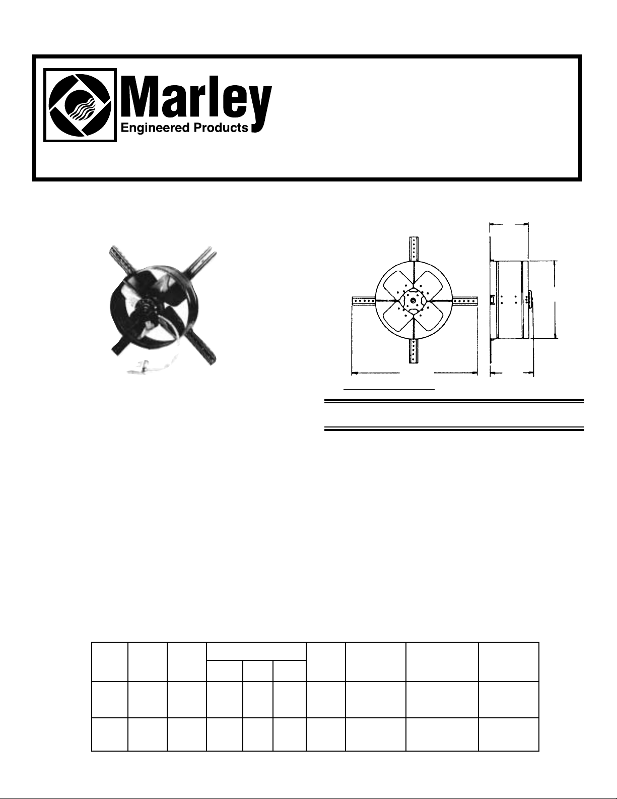
Specifications
MOTOR
* H.V.I. Certified at 0.03” Static Pressure
Figure 2
— Dimensions
1. Do not use this fan with any Solid-State Speed Control Device.
2. Use this unit only in the manner intended by the manufacturer. If you
have questions, contact the manufacturer.
3. Before servicing or cleaning unit, switch power off at service panel and
lock service panel to prevent power from being switched on accidentally.
4. Installation work and electrical wiring must be done by qualified person(s) in accordance with all applicable codes and standards, including
fire-rated construction.
5. Sufficient air is needed for proper combustion and exhausting of gases
through the flue (chimney) of fuel burning equipment to prevent back
drafting. Follow the heating equipment manufacturer’s guideline and
safety standards such as those published by the National Fire Protection
Association (NFPA), and the American Society for Heating and Air
Conditioning Engineers (ASHRAE), and the local code authorities.
Dimensions 7”
16
9
⁄16”
32
13
⁄16”
8
5
⁄8”
Page 2
UNRESTRICTED WOOD LOUVER METAL LOUVER
5.1 Sq. Ft. 6.4 Sq. Ft. 5.9 Sq. Ft.
6. “When cutting or drilling into wall or ceiling, Do Not damage
electrical wiring or other hidden utilities.
7. CAUTION: This unit has an unguarded impeller. Do not use in
locations readily accessible to people or animals.
8. CAUTION: For general ventilation use only! Do not use to exhaust
hazardous or explosive materials and vapors.
INSTALLATION
NOTE: For maximum operating efficiency, proper intake air opening must be provided to allow replacement of exhaust air. One
square foot of free open air inlet per 300 CFM of fan capacity is recommended. The best location for air intake is at the opposite end
of the attic. See:
MINIMUM A TTICINTAKEAREA REQUIRED
section.
1. This gable ventilator is designed to mount behind existing
louvers in an attic. If a louver is not present and one must be
installed, it should be mounted in the center of the uppermost
portion of the gable. The area of the louver should be greater
than outlet area of ventilator. (See Figures 4 and 5.)
2. There are four sets of holes spaced 90
º apart in housing,
providing a choice of four depth positions. Reversing brackets
produces eight positions. Select proper mounting holes to
align bracket and mounting structure on louvers. (See Fig. 3.)
Figure 3
— Mounting Housing to Brackets
3. Ventilator may be mounted directly against a gable louver as
shown in Figure 4. If louver is sufficiently strong, mounting
brackets may be nailed or screwed onto it.
Figure 4
— Mounting to Gable Louvers
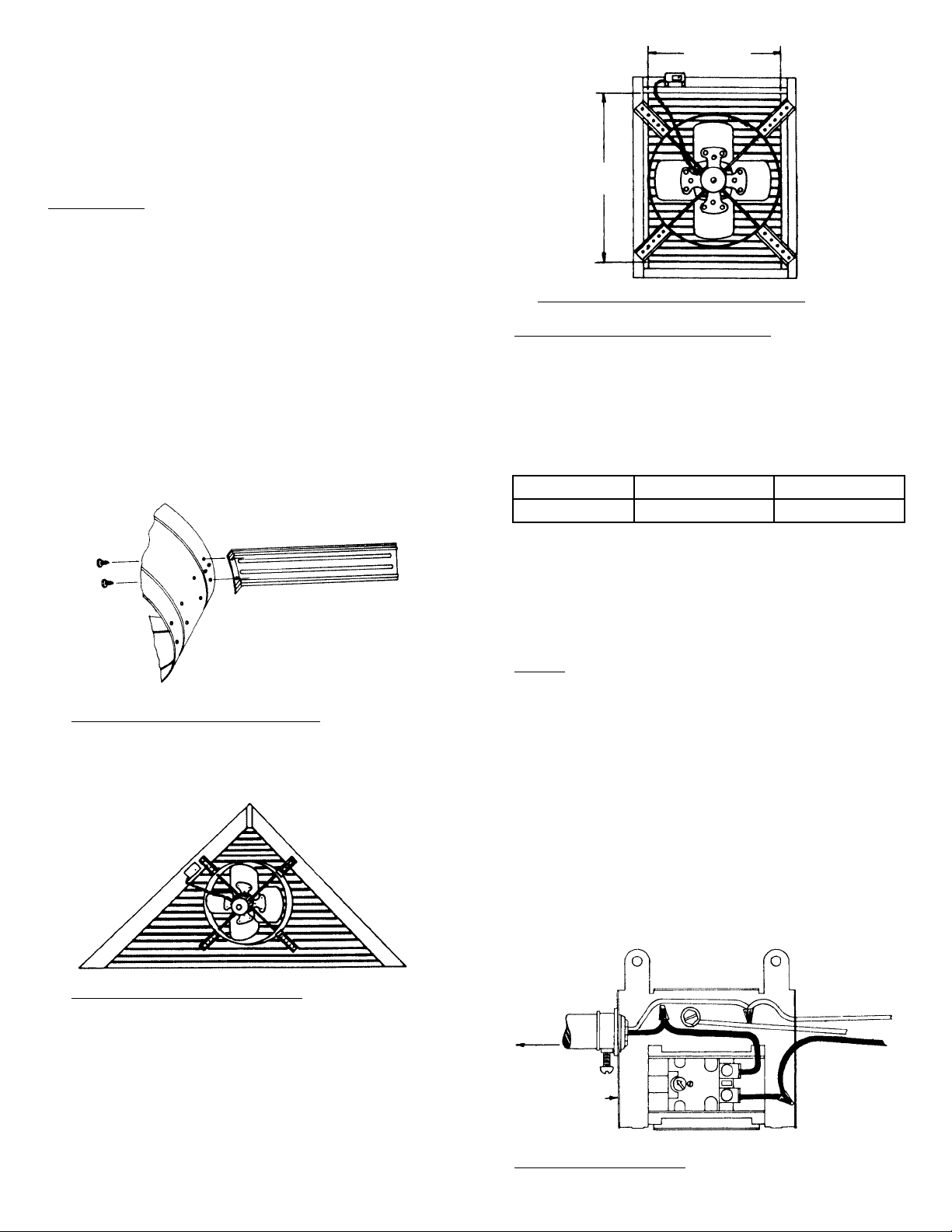
4. If mounting the vent directly to gable louver is undesirable, a
pair of furring strips may be suspended vertically at a minimum
of 16 3/4” apart.
5. Ventilator may also be mounted on rectangular louvers as
shown in Figure 5.
6. For better performance, cover any open louvered area around
vent with plywood or other suitable material. This will improve
efficiency of air exchange between attic and outside air. It will
also prevent thermostat from being directly affected by outside
air.
Figure 5
— Mounting to Rectangular Louvers
MINIMUM ATTIC
INTAKE
AIR REQUIRED
Sufficient intake area must be provided in the attic to ensure that
fan will not be overloaded and that it will deliver its rated CFM. This
can be accomplished with some type of attic venting such as gable
louvers or undereave vents. The table below shows minimum
intake area needed for each fan installed.
MINIMUM ATTIC INTAKE OPENING REQUIRED
Note: If openings are covered with 1/2” hardware cloth or large
mesh expanded metal, increase area by 20%. Double area if fly
screen is used.
WIRING
WARNING: TO REDUCE RISK OF FIRE OR ELECTRIC
SHOCK, DO NOT USE THIS FAN WITH ANY SOLID STATE
SPEED CONTROL DEVICE.
Note: This fan is designed to run on 120V, 60 HZ power only.
1. Thermostat box can be screwed or nailed to a rafter by
mounting bracket provided. If nailed, remove thermostat from
box before nailing to avoid damage. Connection to existing
circuit must conform to local electrical code regulations.
2. Wiring of this unit is done inside attic. Remove cover from
thermostat/junction box. Bring power cable at least 6 inches
into the box. Fasten power cable to box with appropriate
connector.
3. For standard installation, connect the two leads in thermostat/
junction box to the two supply leads. Attach ground wire from
the supply to the green ground screw in the box. (See Fig. 6.)
F
igure 6 — Wiring Diagram
163⁄4” MIN.
16
3
⁄4” MIN.
120V, 60 Hz
SUPPLY
WHITE
GROUND
BLACK
TO FAN
MOTOR
THERMOSTAT &
JUNCTION BOX
ASSEMBLY
Page 3

Excessive 1. Propeller blade contacting 1. Realign or replace.
noise. housing.
2. Foreign material inside 2. Clean.
housing.
3. Motor loose. 3. Secure properly.
4. Motor needs oiling. 4. See Maintenance section.
5. Dirt accumulation on pro- 5. Clean.
peller, causing imbalance.
Insufficient 1. Not enough eave vents to 1. See installation section.
air flow. provide make-up air.
2. Clogged screen. 2. Clean or replace.
Unit fails to 1. Blown fuse or open cir- *1. Replace fuse or reset ciroperate. cuit breaker. cuit breaker.
2. Defective motor. *2. Replace.
3. Improper setting of ther- *3. See Operation section.
mostat. (REMEMBER THE
15
º DIFFERENTIAL)
4. Defective thermostat. *4. Replace
SYMPTOM POSSIBLE CAUSE CORRECTIVE ACTION
MAINTENANCE
WARNING: MOTORS ARE THERMALLY PROTECTED
AND AUTOMATICALLY TEMPERATURE CONTROLLED AND MAY START WITHOUT WARNING.
THEREFORE, MAKE CERTAIN THAT POWER SOURCE
IS DISCONNECTED BEFORE ANY ATTEMPT TO SERVICE OR DISASSEMBLE ANY COMPONENTS! IF
POWER DISCONNECT IS OUT-OF-SIGHT, LOCK IT IN
THE OPEN POSITION AND TAG TO PREVENT APPLICATION OF POWER.
Lubricate motor every 6 months using SAE 20 non-detergent oil.
Insert 2-3 drops of oil in the oiling hole on the back plate of the
motor.
4. See Fig. 7 for wiring dehumidistat to ventilator.
TROUBLESHOOTING CHART
WARNING: ITEMS MARKED WITH AN ASTERISK (*)
SHOULD BE PERFORMED ONLY BY EXPERIENCED AND
QUALIFIED PERSONNEL.
Figure 7 — W
iring Diagram for Dehumidistat
5. Replace cover to thermostat/junction box.
OPERATION
Set automatic thermostat to meet your requirements. The thermostat has an adjustable range from 60
º to 120º and operates on
a 15
º differential. For example, factory setting is 100º. At this set-
ting, as soon as temperature reaches 115
º, thermostat will close
and start ventilator. When temperature has been reduced to 100
º,
thermostat will open and ventilator will stop. Dial pointer may be
set at temperature that is best for local conditions.
NOTE: Remember the 15
º differential. If dial point is set on 120º,
ventilator will start at 135
º and operate until temperature has been
reduced to 120
º, a difference of 15º. (See Figure 8.)
Figure 8
— Thermostat
120V, 60 Hz
SUPPLY
WHITE
GROUND
BLACK
DEHUMIDISTAT
TO FAN
MOTOR
THERMOSTAT &
JUNCTION BOX
ASSEMBLY
F
A
N
O
F
F
90
60ºF
120
Page 4

Part No. 5200-2550-000 PPD 035
3-00
PARTS LIST
REF. NO. DESCRIPTION QTY.
1 FAN BLADE ASSEMBLY 1
2 SHROUD ASSEMBLY 1
3 + SHROUD 1
4 + POP RIVET, 1/8 X 1/8 STEEL 8
5 * SCREW 1/4”- 20 X 1.5” 2
6 + MOTOR BAND 1
7 + MOTOR BRACKET 4
8 SPEED NUT, 1/4 X 20 1
9 + RIVET, 1/8 X 5/32 STEEL 8
10 MOTOR, PSC 115V 1/5 HP 1
11 BOOT, CAPACITOR TERMINALCOVER 1
12 CAPACITOR, 4 MFD, 370 VAC 1
13 * KEPS NUT, #8-32 1
14 CUP, BX 1
15 CONDUIT, FLEXIBLE 1
16 THERMOSTAT ASSEMBLY 1
17 + BX CONNECTOR 1
18 ANTI SHORT BUSHING 1
19 MOUNTING BRACKET 4
20 * SCREW #8 X 3/8” TYPE AB 8
21 † INSTRUCTION SHEET 1
* STANDARD HARDWARE ITEM AVAILABLE
LOCALLY
+ NOT A VAILABLE AS AREPLACEMENT PART
† ITEM NOT SHOWN
HOW TO ORDER REPAIR PARTS
In order to obtain any needed repair or replacement
parts, warranty service or technical information, please
contact Marley Engineered Products Service Center tollfree by calling 1-800-642-HEAT.
When ordering repair parts, always give the information listed as follows:
1. The Part Number
2. The Model Number
3. The Part Description
4. Date of Manufacture
SPX Corporation
470 Beauty Spot Rd. East
Bennettsville, SC 29512 USA
 Loading...