

Marley Engineered Products Electric Radiant Ceiling Heat Panels User Manual
a
Electric Radiant
Ceiling Heat
Panels
Installation & Maintenance Instructions
a
Read Carefully - These instructions are written to help you prevent
difficulties that might arise during installation of heaters. Studying the
instructions first may save you considerable time and money later.
Observe the following procedures and cut your installation time to a
minimum.
1. To prevent possible electrical shock, disconnect ALL power coming to heater at main service panel before wiring or servicing.
2. All wiring must be in accordance with the National and Local
Electrical Codes and the heater must be grounded as a precaution against possible electrical shock.
3. Verify the power supply voltage coming to the heater matches the
ratings printed on the heater nameplate before energizing.
4. This heater is NOT suitable for use in hazardous locations as
described by the National Fire Protection Association (NFPA).
DO NOT use in areas where gasoline, paint or other flammable
liquids are used or stored. DO NOT use in wet areas or areas
where corrosive agents are present, such as marine, green
house, chemical storage, swimming pool, or areas of high
humidity, unless special custom panels are used. Special custom
panels may be available for certain environments. Contact manufacturer for details.
5. To prevent a possible injury or fire from falling panels, panels
MUST be securely fastened to the building structure.
When T
-bar Mounted: The T-bar grid work frame must be
secured to the building to provide adequate support for the panels. Holes are provided in the sides of each panel for attachment
of steel support wires for additional support of the panels where
the T-bar grid work frame strength is questionable. Support wire
must be steel and at least 18 gage (0.047 in. dia. / 0.119 cm. dia).
When Surface or Recess Mounted:
The surface or recess mounting frame accessory kits (Models ASF . . . or ARF . . . ) must be
used. Kits must be sized to match heaters being used. Do not
drill holes, drive nails, screws, etc., into or through panels. To do
so may result in fire, electric shock, or permanent damage to
heater. Surface or recess kits must be securely fastened to building structure using a minimum of four (4) 1/4 inch (.635 cm) diameter screws or bolts.
6. To prevent possible fire due to the overheating of wiring, all field
wiring coming to heating panels must be rated at least 90° C
when junction box is allowed to lie on top of heating panel or is
enclosed between heater and ceiling above. When thermal insulation is used on top of heater, the junction box must be above
the insulation.
7. Panels are intended for ceiling installation only. Do not install on
walls, floor, etc. Painted (bottom) surface of panel is hot. Panels
must be installed at least seven (7) feet off floor and should not
be installed where panels can be easily contacted during use.
WARNING
SA VE THESE INSTRUCTIONS
Dear Owner,
Congratulations! Thank you for purchasing this new heater manufactured by a division of Marley
Engineered Products. You have made a wise investment selecting the highest quality product in the heating industry. Please carefully r ead the installation and maintenance directions shown in this manual. You
should enjoy years of efficient heating comfort with this product from Marley Engineered Products . . .
the industry’s leader in design, manufacturing, quality, and service.
. . . The Employees of
Marley Engineered Products
FILE #E21069
Marley Engineered Products Radiant Heating Panels are
designed to provide comfort by warming the surfaces
below the heaters just as the sun warms surfaces through
radiant energy. This heating process heats objects in a
room without having to bring the room air temperature up
to the same level. These panels are ideal for spot heating
in high heat loss areas. Panels may be installed side by
side or individually above areas requiring additional heat. If
used as a sole source of heat, more heat will be felt while
standing directly under the panel.
Although the heater contains thermal insulation, it will
operate more efficiently in well insulated rooms. Four or
more inches of insulation above an exposed ceiling will
increase both comfort and economy.
The heaters are intended to be controlled by a remote wall
mounted thermostat. The thermostat should be located in
the same room on a side wall. It should also be above
five feet above the floor, but not directly under the heater.
GENERAL
1
!
NOTE: For a period of time after the panels are put into
operation the owner may notice a “new smell” coming
from the heaters. This is expected on new installations
and will dissipate after approximately 24 hours of operation.
PAINTING
1. Heaters may be repainted. Do not remove paint from
heaters. The surface must be first free of grease or
oil. Use only a thin brush-on coat of high quality pure
acrylic water base flat latex. An off-white will give better
coverage.
Do not paint with aluminum, oil base, vinyl-latex or
rubber-base latex paint.
T-BAR MOUNTING
1. The heater panels are designed for installation in T-Bar
ceilings.
2. Three (3) inch (7.67cm) minimum distance must be provided between the front painted surface and the ceiling
above. However, installation may be difficult and six (6)
inches (15.2 cm) or more clearance will improve installation of heaters and inspection or wiring. It may be necessary to remove a cross tee for installation when T-Bars
are at the close distances to the ceiling.
3. Locate T-Bar hanger wires at the corners where the
cross tees intersect the main tees so that they do not
interfere with installation or removal of panels.
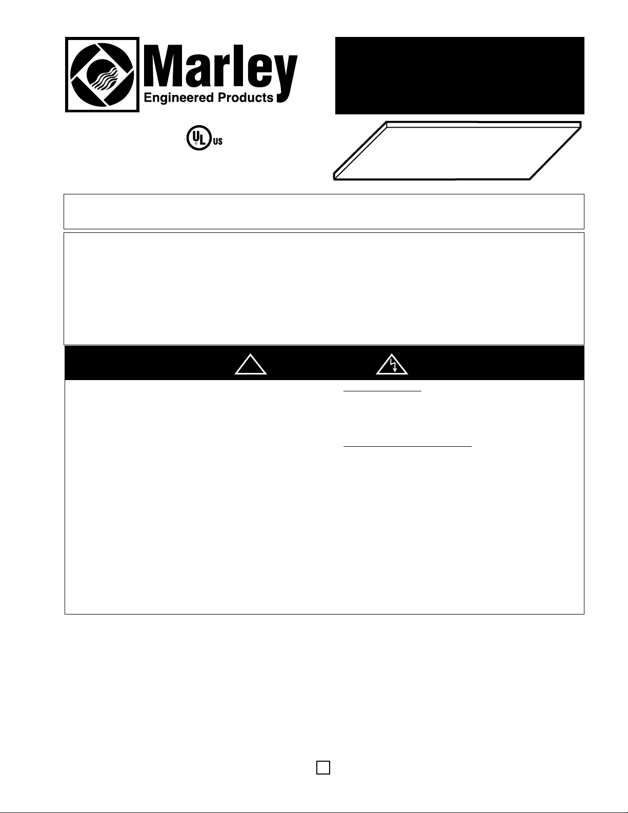
4. The heater panels are supplied with four hold-down
clips. Install two hold-down clips on each short side of
the heater panel (see Fig. 1). Wedge the short end of the
clip behind the heating panel flange.
5. Carefully lift heater panel into place, making sure holddown clips hook securely over T-bar.
WIRING
1. Maximum number of heaters per circuit is limited to circuit wiring and thermostat or switch capacity. See catalog for available thermostats and Warning No. 2.
2. Make wiring connections in accordance with Fig. 3 (on
following page) and wiring instructions. The heater must
be properly grounded as a precaution against electrical
shock. Use a properly grounded junction box for connecting the heater to the power supply.
3. Always use a properly grounded junction box when
splicing. See wiring diagrams for proper connections.
Install only in a location where the power supply con-
nections will be accessible. Install junction box as far
above panel as possible and above building insulation,
where present. Use field wiring suitable for 90 ºC if
junction box is allowed to lie on heater or is enclosed
between heater and ceiling above. When installed in a
drop ceiling, the wiring terminals should be accessible
through removable ceiling sections with adequate clearance to permit access to the top of the heater.
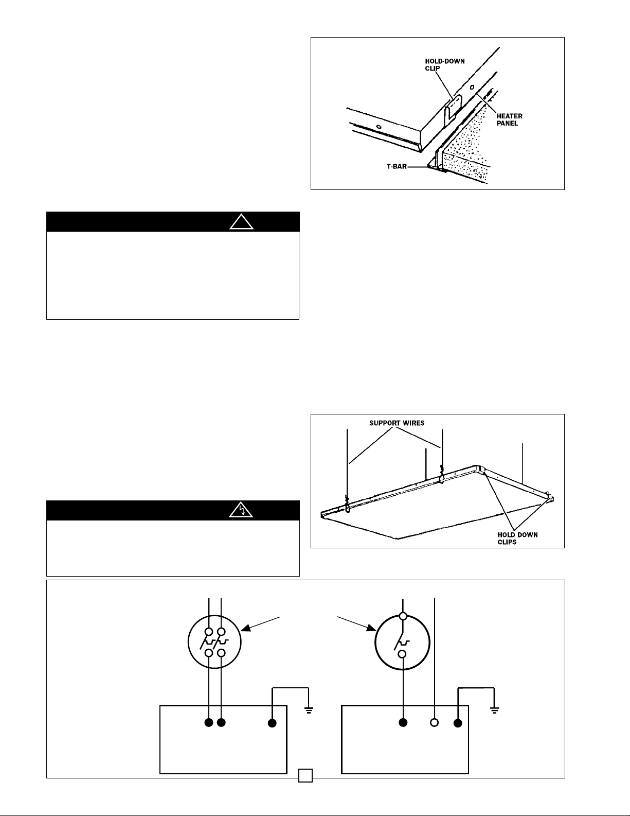
To prevent possible injury from falling panels, the T-Bar
must be securely fastened to the building structure and
capable of supporting the weight of the panel (30
pounds). Extra holes are provided for suspending the
heater panel (see Fig. 2) on steel wires no smaller than
No. 18 ga. (0.047 in. diameter / 0.119 cm diameter).These
extra support wires must be used where T-Bar strength
is inadequate or where vibration is anticipated.
CAUTION
To prevent possible injury from electric shock, make
sure that electricity is turned off at the main switch. All
wiring must be done in accordance with national and
local codes and the unit must be properly grounded as
a precaution against electrical shock.
CAUTION
Fig. 1
Fig. 2
Fig. 3
2
!
SEE NAMEPLATE FOR
LINE VOLTAGE SUPPLY
SEE NAMEPLATE FOR
LINE VOLTAGE SUPPLY
WIRING
DIAGRAM
HEATERS MUST BE
PROPERLY GROUNDED
BLACK
BLACK G
208 OR 240 VOLT
HEATER
LINE VOLTAGE
THERMOSTAT
OR SWITCH
(NOT INCLUDED -
SEE CATALOG)
BLACK WHITE
120, 277 OR 347 VOLT
HEATER
G
 Loading...