

Page 1
This low voltage room thermostat opens on temperature
rise and is designed for use on various types of heating
equipment. It is equipped with a heat anticipator which
may be adjusted for primary control current draws of .15
to 1.0 Amps.
SELECTION LOCATION
The proper location of the room thermostat is most
important to insure that it will provide a comfortable
ambient temperature. Observe the following general
rules when selecting a location:
1. Locate it about 5 ft. above the floor.
2. Install it on a partitioning wall, not on an outside, windows, or adjoining outside walls.
3. Never expose it to direct light from lamps, sun, fire
places, etc.
4. Avoid locations close to doors that lead to outside,
windows, or adjoining outside walls.
5. Avoid locations close to radiators, warm air registers, or
in the direct path of heat from them.
6. Make sure there are no pipes or duct work in that part of
the wall chosen for the thermostat location.
7. Never locate it in a room that is warmer or cooler than the
rest of the home, such as kitchen or hallway.
8. The living or dining room is normally a good location,
provided there is no cooking range or refrigerator on
opposite side of wall.
ROUTING WIRES T O LOCATION
1. Before drilling hole in wall at selected location, take up
quarter round and drill a small guide hole for sighting.
From basement, drill 3/4" hole in partition floor next to
guide hole. (On basementless houses, drill 1/2" hole
through ceiling above partition.)
2. Probe for obstructions in the partition. Then drill 1/2"
hole through wall at selected location.
3. Through this hole in wall drop a light chain, or 6" chain
attached to a strong cord, and snag cord with hooked
wire from basement. (On basementless houses, drop
cord from ceiling and snag it at the thermostat location.)
4. Attach thermostat cable to cord and pull cable through
hole in wall so that 6" of cable protrudes.
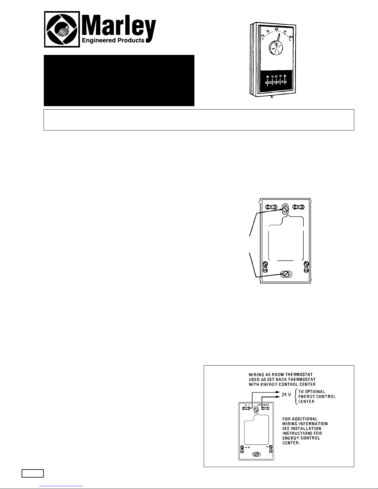
MOUNTING THERMOST A T
1. Pull thermostat wires through large hole in center of wall
mounting plate and fasten wires beneath two terminal
screws on bottom side of plate.
2. Push excess wire into wall or switch box and plug up hole
to prevent drafts from affecting thermostat operation.
3. Thermostat must be level to assure optimum performance.
Place level on top of wall mounting plate and mark hole
locations for mounting screws provided. Again place
level on top of plate to be sure it is level. Then tighten
screws.
4. Remove cover from thermostat base by pulling outward.
Remove and discard pad (shipping protection for switch).
Place thermostat base onto wall mounting plate and
tighten all three screws securely. Then snap on
thermostat cover.
WIRING
All wiring should be done according to local
and national electrical codes and ordinances.
WIRING AS ROOM THERMOSTAT
Because of the many possible uses of these room thermostats, no wiring diagrams are presented. Use the wiring
diagram that is shown on the instruction sheet that is packed
with the primary control, or the one that is supplied by the
manufacturer of the heating equipment.
LO W VOL TA GE
ROOM THERMOST A T
Catalog Number WR-1E30-S
MOUNTING
SCREWS
WALL
MOUNTING
PLATE
UP VERT
9
A
R
5
4
Installation Instructions
1
Page 2
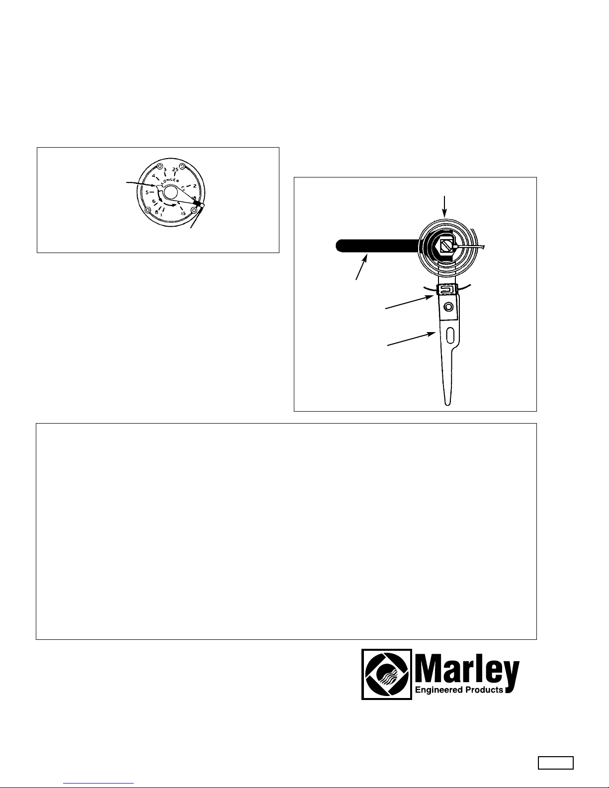
HEAT ANTICIPATION (Figure 1)
This thermostat is equipped with an adjustable heat anticipator.
Set heater indicator to match the current rating of
the primary control.
The heater may be adjusted for cur-
rent ratings from .15 to 1.0 Amps.
Adjustments
Cycles too long
— Set adjustable heater to a slightly
lower dial setting (1/2 division).
Cycles too short — Set adjustable heater to a slightly
higher dial setting (1/2 division).
CALIBRATION ADJUSTMENT (Figure 2)
These thermostats have been carefully adjusted at the factory and should not require re-calibration.
A few degrees difference between the indicator setting of
the thermostat and actual room temperature is not considered too important. However, if the temperature is much
greater, first make sure that the thermostat is properly located and leveled. Then, if re-calibration still seems necessary, proceed as follows:
1. Move temperature adjustment level to a setting about
5°
above room temperature.
2. Remove thermostat cover. Slip standard 7/32" wrench
onto hex nut beneath bimetal, and, holding temperature
adjustment lever stationary, turn hex nut
clockwise until
mercury shifts to right end of tube.
3. Move temperature adjustment lever to lowest setting.
4. Replace thermostat cover. Wait 10 minutes for bimetal
temperature to stabilize. Don’t stand near thermostat
during this period as your breath and body heat will
affect the temperature of the bimetal.
5. Move temperature adjustment lever to correspond to
actual room temperature. Then remove thermostat
cover.
6. Slip 7/32" wrench onto hex nut, holding temperature
adjustment lever stationary, turn hex nut
counterclock-
wise
until mercury just barely shifts to left end of tube.
Then replace cover and set thermostat to desired
tem perature.
HOW TO ORDER REPAIR PARTS
In order to obtain any needed repair or replacement parts, warranty
service or technical information, please contact Marley Engineered
Products Service Center toll-free by calling 1-800-642-HEAT.
When ordering repair parts, always give the information listed as follows:
1. The Part Number 3. The Part Description
2. The Model Number 4. Date of Manufacture
ECR 32524
5/95
5200 0918 002
2
HEATER INDICATOR
(MOVE INDICATOR
TO MATCH CURRENT
RATING OF PRIMARY
CONTROL.)
USE THIS LEVER TO
ADJUST INDICATOR
BIMETAL
STANDARD 7 / 32" WRENCH
SET BACK RESISTOR
TEMPERATURE
ADJUSTMENT
LEVER
FIGURE 2
FIGURE 1
LIMITED W ARRANTY
All products covered by this instruction sheet are warranted against defects in workmanship and materials for one year from
date of installation. This warranty does not apply to damage from accident, misuse, or alteration; nor where the connected
voltage is more than 5% above the nameplate voltage; nor to equipment improperly installed or wired or maintained in violation of this instruction sheet. All claims for warranty work must be accompanied by proof of the date of installation.
The customer shall be responsible for all costs incurred in the removal or reinstallation of products, including labor costs,
and shipping costs incurred to return products to a Marley Engineered Products Service Center, and we will repair or
replace, at our option, at no charge to you with return freight paid by Marley. It is agreed that such repair or replacement is
the exclusive remedy available from Marley Engineered Products.
THE ABOVE WARRANTIES ARE IN LIEU OF ALL OTHER WARRANTIES EXPRESSED OR IMPLIED, AND ALLIMPLIED
WARRANTIES OF MERCHANTABILITY AND FITNESS FOR A PARTICULAR PURPOSE WHICH EXCEED THE AFORESAID EXPRESSED WARRANTIES ARE HEREBY DISCLAIMED AND EXCLUDED FROM THIS AGREEMENT. MARLEY
ENGINEERED PRODUCTS SHALL NOT BE LIABLE FOR CONSEQUENTIAL DAMAGES ARISING WITH RESPECT TO
THE PRODUCT, WHETHER BASED UPON NEGLIGENCE, TORT, STRICT LIABILITY, OR CONTRACT.
Some states do not allow the exclusion on limitation of incidental or consequential damages, so the above exclusion or limitation may not apply to you. This warranty gives you specific legal rights, and you may also have other rights which vary
from state.
For the address of your nearest authorized service center, contact Marley Engineered Products, 470 Beauty Spot Road
East, Bennettsville, SC 29512 USA. Merchandise returned to the factory must be accompanied by a return authorization
and service identification tag, both available from the above location. When requesting return authorization, include all catalog numbers shown on the product.
SPX Corporation
470 Beauty Spot Rd. East
Bennettsville, SC 29512 USA
 Loading...