

Marley WH4407, WH4307, WH4408, WH44083, WH44043 Installation & Maintenance Instructions Manual
...
WH Series
Fan Forced
Wall Heaters
Dear Owner,
Congratulations! Thank you for purchasing this new heater manufactured by Marley Engineered
Products. You have made a wise investment selecting the highest quality product in the heating industry. Please carefully read the installation and maintenance directions shown in this manual. You should
enjoy years of efficient heating comfort with this heater from Marley Engineered Products... the industry’s leader in design, manufacturing, quality and service.
... The Employees of
Marley Engineered Products
Installation & Maintenance Instructions
Read Carefully - These instructions are written to help
you prevent difficulties that might arise during installation
of heaters. Studying the instructions first may save you
considerable time and money later. Observe the following
procedures, and cut your installation time to a minimum.
TO REDUCE RISK OF FIRE OR ELECTRIC SHOCK:
1. Disconnect all power coming to heater at main service panel
before wiring or servicing.
2. All wiring must be in accordance with the National and Local
Electrical Codes and the heater must be grounded.
3. Verify the power supply voltage coming to heater matches the
ratings printed on the heater nameplate before energizing.
4. This heater is hot when in use. To avoid burns, do not let bare
skin touch hot surfaces.
5. Do not insert or allow foreign objects to enter any ventilation
or exhaust opening as this may cause an electric shock,
fire,or damage to the heater.
6. Do not block air intakes or exhaust in any manner. Keep
combustible materials, such as crates, drapes, etc., away
from heater. Do not install behind doors, furniture, towels,
or boxes.
7. A heater has hot and arcing or sparking parts inside. Do not
use it in areas where gasoline, paint, or flammable liquids are
stored.
8. Use this heater only as described in this manual. Any other
use not recommended by the manufacturer may cause fire,
electric shock, or injury to persons.
9. This heater is not approved for use in corrosive atmospheres
such as marine, green house, or chemical storage areas.
SAVE THESE INSTRUCTIONS
WARNING
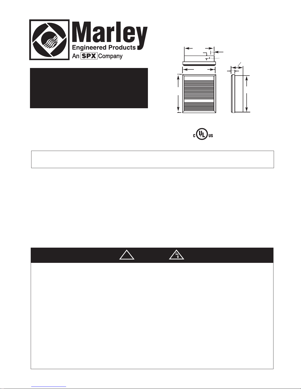
2" (50.8mm)
1-5/16" (33mm)
1-21/32"
(42mm)
5/14"
(133mm)
Knockout
14-3/8"
(365mm)
19-3/16"
(487mm)
18-1/4"
464mm
15-21/64"
(389mm)
File E21609
!
Installation of Recessed Back
Box in New Construction
1.Mounting Back Box (See Figure 1).
a. Place the back box between two 16" (406 mm) center-to-center wall
studs at the desired mounting height but no closer than 8" (203 mm)
to adjacent wall or floor.
Note: If wall studs are spaced greater than 16” on center, additional
framing supports may be necessary.
b. Align back box such that the bottom and sides will be flush with
finished wall surface (top flange of back box should protrude approximately 1/2" (12.7 mm) from finished wall surface).
c. Secure the back box in position with wood screws or nails as shown
in Figure 1.
2.Power Supply Wiring (See Figure 1)
Note: Wire compartment volume - 119in
3
(1950cm3).
a. Run a power supply cable into the knockout area in the upper right
hand corner of the back box. All wiring must be in accordance with
National and Local Electrical Codes. Refer to Table 1 for correct
wire size.
b. Remove disconnect switch bracket by loosening two screws on the
right side.
c. Install a cable clamp in the “knockout” in the top of the back box.
d. Insert power supply cable through cable clamp, allowing at least 6"
(152mm) of leads to extend inside the back box. Connect the blue
lead wires of disconnect switch to the supply wire leads using wire
connectors (see wiring diagram, pg. 4).
e. Ground the back box using the green screw located in the inside top
of the back box.
f. Secure disconnect switch bracket in place by tightening screws.
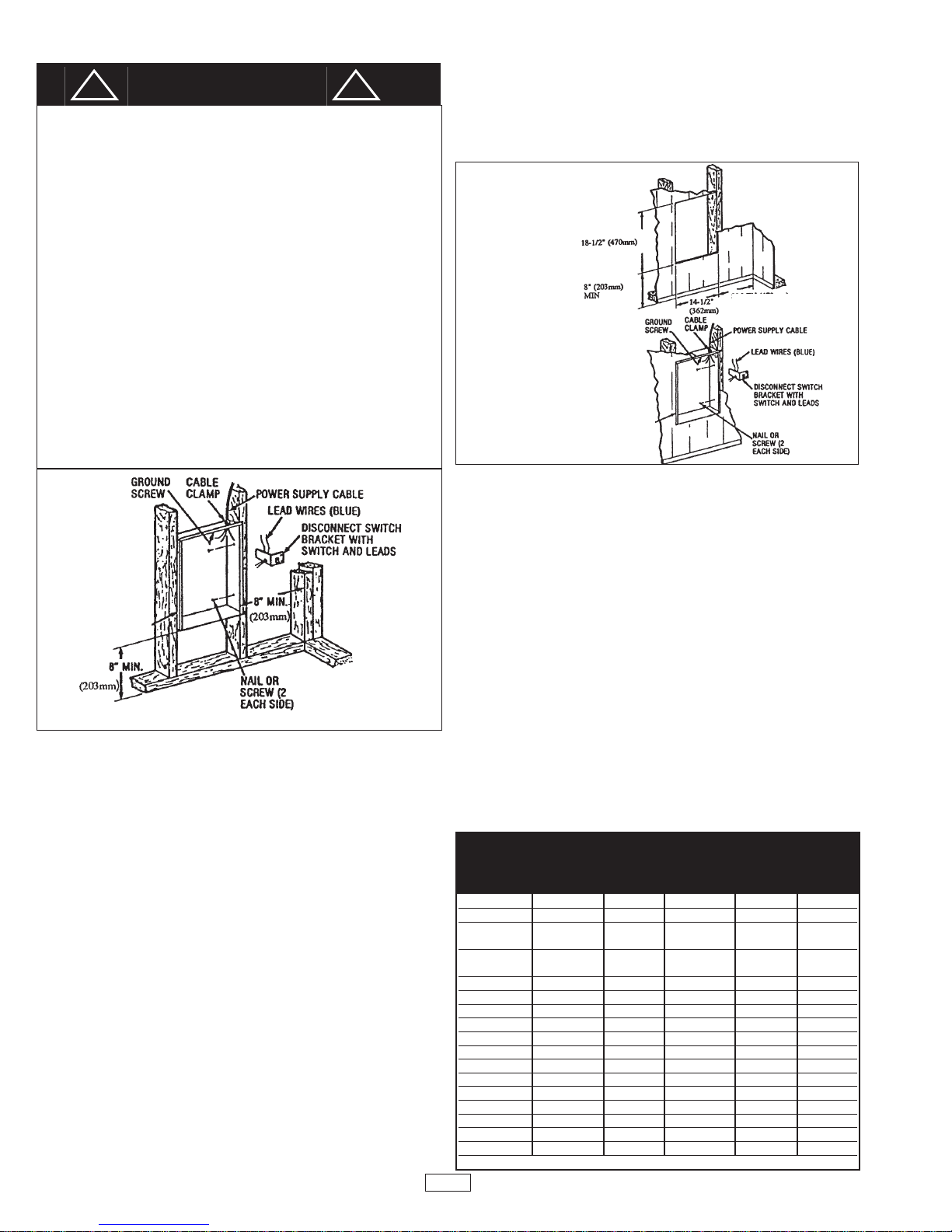
Installation of Recessed Back Box
in Existing Construction
1. Provide a wall opening 14-1/2" (362mm) wide by 18-1/2" (470mm) high
at the desired mounting height, but no closer than 8" (203mm) from floor.
(See Figure 2.)
Note: Locate so at least one side of opening is at wall stud.
2. Power Supply Wiring
Note: Wiring Compartment Volume - 119in
3
(1950cm3).
a. Run a power supply cable into the area above the top of the wall open-
ing. All wiring must be in accordance with National and Local electrical
codes. Refer to Table 1 for correct wire size.
b. Remove disconnect switch bracket by loosening the two screws on the
right side.
c. Install a cable clamp in the “knockout” in the top of back box.
d. Insert power supply cable through cable clamp, allowing approximate-
ly 6" (152mm) of cable length to remain inside the back box to facili-
tate connections.
3. Mounting Back Box
a. Place the back box into wall opening flush with finished wall surface on
bottom and sides of box. (Top flange of back box should protrude
approximately 1/2" or 12.7mm from finished wall surface).
b. Secure the back box in place with wood screws or nails.
4. Wiring Disconnect Switch
a. Connect the power supply wires to the blue wires of the disconnect switch
using wire connectors (see wiring diagram,pg. 4.)
b. Ground the back box using the green ground screw located in the
inside top of the back box.
c. Secure disconnect switch bracket in place by tightening screws.
CAUTION
FOR SAFE OPERATION AND REDUCED RISK OF FIRE, INJURY OR
HEATER DAMAGE, OBSERVE THE FOLLOWING:
1. Do NOT use a remote thermostat with this heater. Built in thermostat
cycles the heating element only. Fan delay control automatically turns
fan ON and OFF, and provides a fan delay OFF feature to remove
residual heat after thermostat has turned heating elements off. Wiring
of heater in any manner which defeats the fan delay OFF feature can
result in overheating and permanent damage to heater, and will void
the warranty.
2. For wall mounting only with air discharge downward. Do NOT install
in floor, ceiling, upside down (air discharge upward), or sideways.
3. Do NOT operate heater without grille installed.
4. Maintain the following clearances:
• Bottom of heater to floor – 8” (203mm)
• Sides of heater to adjacent wall – 8” (203mm)
• Top of heater to ceiling – 36” (915mm)
5. This heater is hot when in use. Do NOT install heater behind door,
behind towel rack, inside closet, where drapery could touch heater or
be damaged by heat, or where airflow to heater may be obstructed.
Keep electrical cords, bedding, furniture, and other items away from
heater.
6. Heater must be cleaned periodically (at least annually) to assure
proper performance and prevent overheating. See section on
cleaning and maintenance.
Fig. 1: Locating Back Box in New Construction
Fig. 2: Locating Back
Box in Existing Construction
8” (203mm) MIN
!
Back Box
Back Box
Table 1
Min.
Supply
Catalog Wire
Number Volts Phase Watts Amps Gauge
WH3150 120 1 1500 12.5 12
WH3180 120 1 1800 15.0 12
WH4404* 240/208 1
4000/3000 16.7/14.5 10
2000/1500 8.3/7.2 12
WH4407* 277/240 1
4000/3000 14.5/12.5 12
2000/1500 7.2/6.3 12
WH4307* 277 1 3000/1500 10.8/5.4 12
WH4408* 208 1 4000/2000 19.2/9.6 10
WH44083 208 3 4000 11.1 14
WH44043 240 3 4000 9.7 14
WH4303 347 1 3000 8.6 14
WH4306 600 3 3000 3 14
WH4508 208 1 4800 23.1 10
WH4504 208/240 1 3600/4800 17.3/20.0 10
WH4507 240/277 1 3600/4800 15.0/17.3 10
WH45083 208 3 4800 13.3 12
WH45043 240 3 4800 11.6 14
WH4503 347 1 4800 13.8 12
WH4506 600 1 4800 8 14
*NOTE: Factory wired for higher wattage, field convertible to half wattage.
2
!
 Loading...