

Page 1
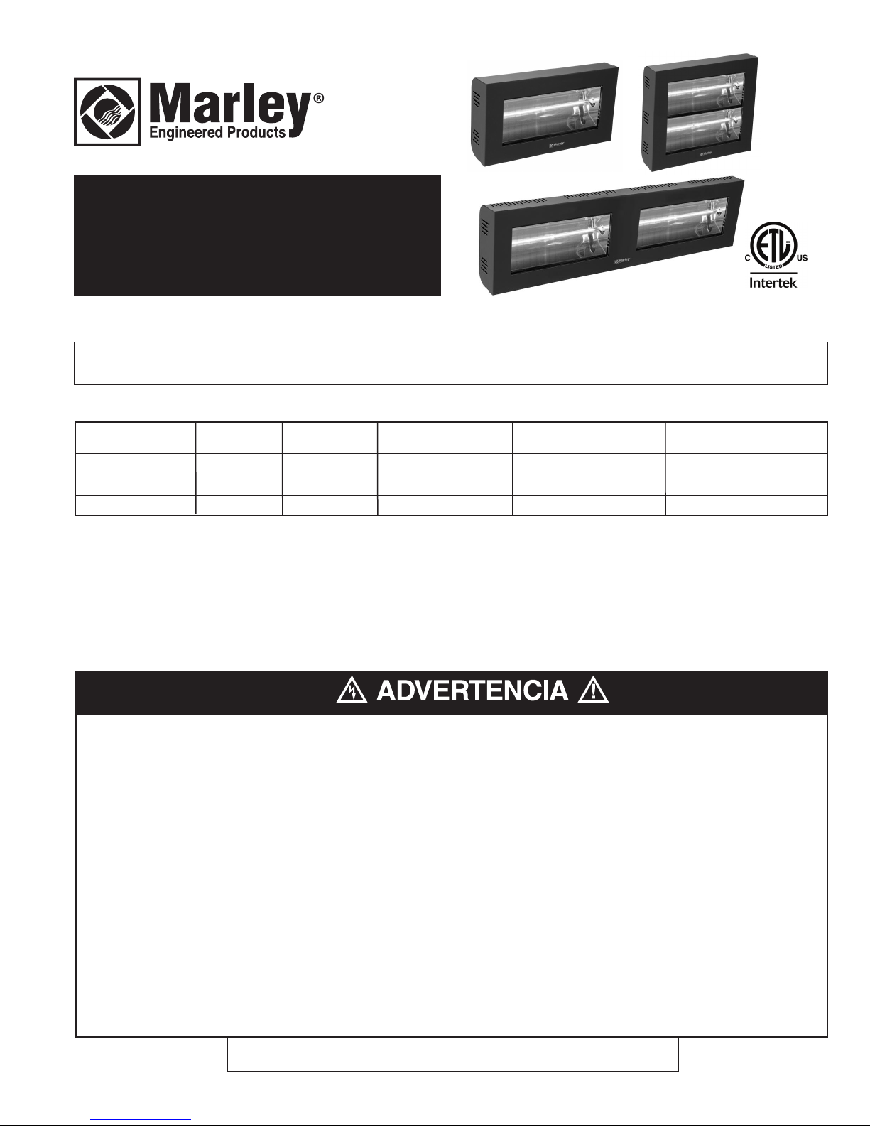
VRC44 Series
Commercial Radiant Heaters
Meets ANSI/UL 2021
nd CSA C22.2 No. 46
a
Installation, Operation & Maintenance Instructions
Table 1. Specifications
MODEL VOLTS PHASE WATTS AMPS BTUHR
VRC4420SG 240 1 2000 8.4 6824
VRC4440DWG 240 1 4000 16.7 13648
VRC4440DTG 240 1 4000 16.7 13648
IMPORTANT INSTRUCTIONS
Read Carefully – This instruction sheet contains vital information for the proper installation, use, and efficient operation
of the heater described. Carefully read this manual before installation, cleaning, or operation of the heater. Failure to
adhere to the instructions could result in fire, electrical shock, death, serious personal injury, or property damage. Save
these instructions and review frequently for continuing safe operation and instructing future users.
WHEN USING ELECTRICAL APPLIANCES, BASIC PRECAUTIONS SHOULD ALWAYS BE FOLLOWED TO REDUCE THE
RISK OF FIRE, ELECTRIC SHOCK, AND INJURY TO PERSONS, INCLUDING THE FOLLOWING:
1. Read all instructions before installing or using this heater.
2. All wiring must comply with the National Electrical Code
(NEC) in the USA, Canadian Electrical Code (CEC) in
Canada and all applicable local codes and the heater must
be grounded..
3. This heater is hot when in use. To avoid burns, do not let
bare skin touch hot surfaces. Keep combustible materials,
such as furniture, pillows, bedding, papers, clothes, etc. and
curtains at least 7 ft. (2.1 M) from the front of the heater.
4. Extreme caution is necessary when any heater is used by or
near children or invalids and whenever the heater is left
operating and unattended.
SAVE THESE INSTRUCTIONS
PPD 48648 11/14 5200-11225-000
5. This heater is IPX5 Rated for use in outdoor areas always
disconnect power to heater before spraying with water.
7. Do not insert or allow foreign objects to enter heater as this
may cause an electric shock, fire, or damage the heater.
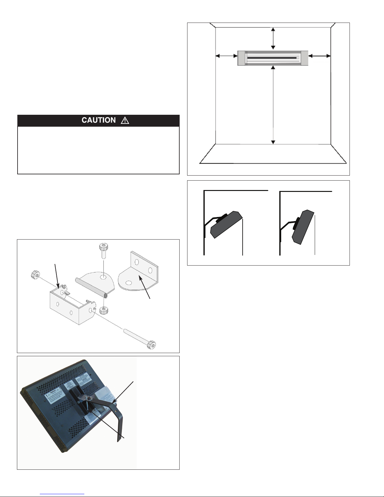
8. To prevent a fire, use care to never block heater and maintain required clearances. See Fig. 2.
9. A heater has hot and arcing or sparking parts inside. Do not
use in areas where gasoline, paint, or flammable vapors or
liquids are used or stored.
10. Use this heater only as described in this manual. Any other
use not recommended by the manufacturer may cause fire,
electric shock, or injury to persons. Do not modify this heater
in any way.
11. Do not use as a residential or household heater.
Page 2
INSTALLATION
45°
WALL
Maximum Tilt
(Recommended)
H
e
ate
r
Ceiling
4°
WALL
Minimum Tilt
Ceiling
He
at
e
r
INSTRUCTIONS
1. Carefully open the carton containing your heater and check
for damage. If you find any damage, notify your carrier as
freight damage is not covered by the manufacturer’s warranty.
File damage claim directly with carrier.
2. Avoid touching the bulb as oils from your hand will cause a
premature failure of the bulb.
Should you accidentially touch the bulb, clean it with a
soft cloth and alcohol.
THIS HEATER OPERATES AT HIGH TEMPERATURES AND
WILL DAMAGE MATERIALS (SUCH AS VINYL SIDING, PLASTICS OR FABRICS) IF THESE TYPE MATERIALS ARE
PLACED TO CLOSE TO HEATER OR IF HEATER IS NOT
INSTALLED PER THESE INSTRUCTIONS. REFER TO FIGS 2
AND 3 FOR CLEARANCE AND MOUNTING INSTRUCTIONS.
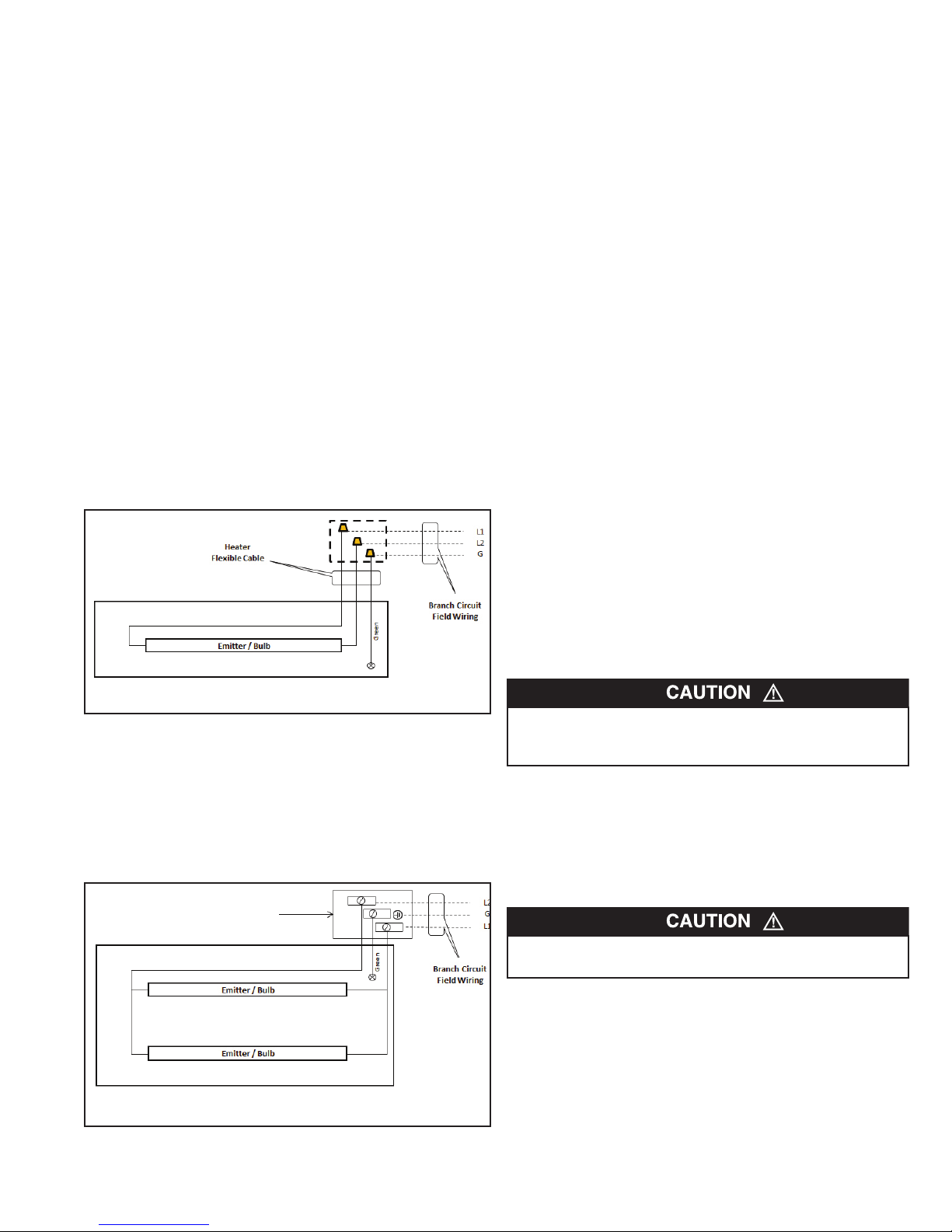
3. This heater is intended for wall mounting only using wall
bracket provided with heater - See Fig. 1. See Fig. 2 for
Minimum Mounting Clearances and Fig. 3 for mounting
instructions..
4. Heater must be installed in horizontal position only and parallel to mounting wall. Do not tilt heater from side to side as
this could cause overheating of adjacent wall or other
objects. (as shown).
12"
(305 mm)
6"
3
914 mm)
(
Model VCR4420SGA -
'3" (2.5 M)
8
odels VCR444DWGA
M
and VCR444DTGA 9'10" (3 M)
Figure 2 - Minimum Mounting Clearances
6"
3
(914 mm)
Bracket Permanently
Attached to Heater
Bracket Permanently
Attached to wall
Figure 1A - Mounting for single bulb model
Figure 1B - Mounting for two bulb models
NOTE: this is angular wall bracket mounting
Wall Bracket Installed
Onto heater - Ready to
Mount to Wall
Factory installed
bracket with stop
bolt - do not
remove or adjust.
Figure 3 - Mounting Angles (Min and Max)
5. Heater must be securely mounted to building structure to
assure it will not fall.
6. Heater is IPX5 Rated for outdoor use.
7. Heater bracket will allow the heater mounting angle to be
adjusted from approximately 4°- 45 ° from vertical. The optimum angle is 45 ° - see Fig. 3
8. Do not locate heater directly below an outlet.
Safety Note: VRC4440DWG and VRC4440DTG models are factory assembled with the heater bracket attached to the heater.
This bracket has a stop bolt installed to provide for the correct
mounting angle. Do not remove or adjust this bolt. To do could
allow the heater to be tilted incorrectly and cause a fire.
WIRING
INSTRUCTIONS
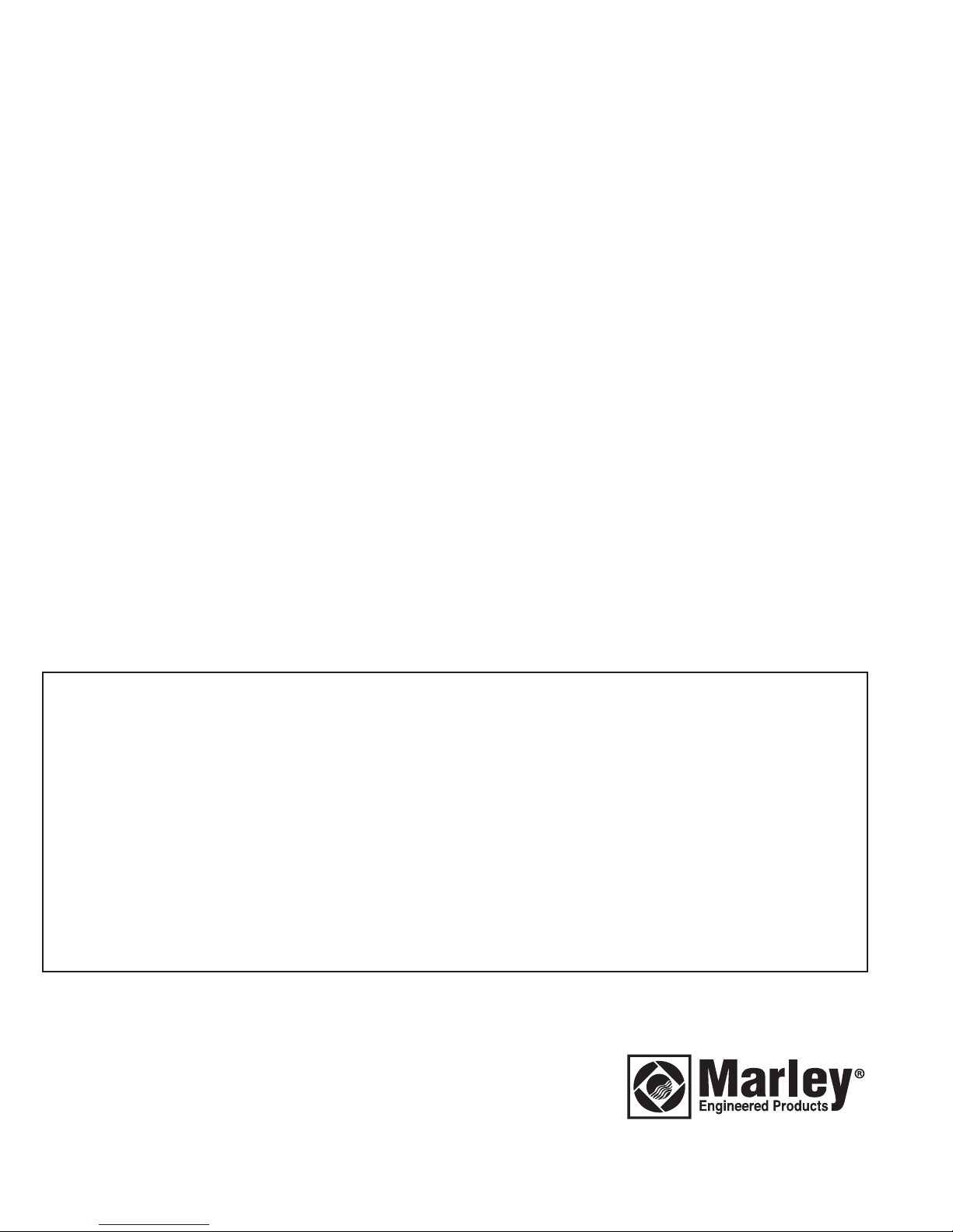
Model VRC4420SG is provided with a flexible power cord for
hard wiring into an approved field wiring box. Models
VRC4440DWG and VRC4440DTG are is provided with a field
wiring compartment for hard wire connection to branch circuit at
the heater. All field wiring coming to heater must be rated 90 °C
min.
Note: Installer must determine how the heater will be controlled
(ON-OFF) and provide branch circuit equipment as needed.
Care must be given if automatic controls such as timers or
programmable
2
Page 3
controllers are used to make sure the heaters are not blocked
and materials are not stored within 7 ft. (2.1 M) distance in front
of heater. It is recommended that these heaters only be used in
attended areas.
Model VRC4420SG (single element):
This model is provided with a section of weatherproof flexible
power cable to allow for ease in wiring. Installer must bring
branch circuit wiring to area near heater location and provide an
approved junction box for making connections. Note: Do not
install heater directly below a junction box.
Warning: To prevent a possible electric shock hazard, make sure
all power coming to heater is OFF at main disconnect before
wiring.
1. Route heater cable to junction box and cut excess cable to
allow approximately 6 inches of cable inside box for wiring
connections.
2. Install appropriate cable clamp/strain relief to cable and
secure into junction box.
3. After removing the outer jacket, strip approximately ½” of
insulation from each wire to assure only the copper wire is
within connectors and make all connections using the appropriate sized listed connectors. Connect the green colored
appropriate conduit. Wiring coming to heater must be rated at
least 90 °C for all connections inside heater junction box. Use
copper wire only.
Warning: To prevent a possible electric shock hazard, make sure
all power coming to heater is OFF at main disconnect before
1. Bring field wiring to heater and install appropriate conduit and
fittings in accordance with the NEC (USA) and CEC
(Canada). Allow 6 inches of wire inside junction box for connections.
2. Connect the earth ground to center terminal marked with
Ground mark making sure connection is tight.
3. Connect the two remaining power wires to the L1 and L2 terminals on terminal block making sure connections are tight to
avoid overheating. – See Wiring diagram Fig.4B.
4. Replace wiring box cover and secure using screws provided.
INITIAL CHECK OUT
1. After all wiring has been completed, energize the heater circuit by turning on the breaker or disconnect switch provided.
Heater should immediately come on.
2. Allow heater to operate for at least 10 minutes to verify all
wiring is correct.
3. Disconnect power.
ield Supplied for VRC4420SG
F
Figure 4A - Wiring Diagram (1 element model shown)
wire from heater to the earth ground wire. Connect the
remaining two heater wires to the two power wires. To avoid
overheating, make sure all connections are tight. See wiring
diagram Fig.4A.
4. Install appropriate junction box cover.B
Models VRC4440DWG and VRC4440DTG
(two element models):
These models are provided with a field wiring box on the back of
the heater. Branch circuit wiring must be routed to heater using
Heater Wiring Box for VRC4440DWG
and VRC4440DTG
OPERATING
INSTRUCTIONS
1. Your heater operates using infrared short wave technology to
heat objects, not the air. Therefore, the heater installation
should direct the rays towards the object(s) needing heat.
TO AVOID A POSSIBLE FIRE DO NOT PLACE ANY OBJECTS
CLOSER THAN 7 FT (2.1 M) IN FRONT OF HEATER OR 36 "
(914 MM) FROM SIDES..
2. Your heater comes completely assembled except for the
attachment of the heater to the wall bracket. Do not operate
your heater unless it is properly installed as indicated in the
INSTALLATION INSTRUCTIONS section.
3. To operate, energize the electrical circuit to heater by turning
on the breaker or disconnect switch feeding the heater.
Heater should immediately come on with bulb lighting up.
NEVER STARE AT BULB DURING OPERATION AS THIS
COULD CAUSE A POSSIBLE EYE INJURY.
Figure 4B - Wiring Diagram (2 element model shown)
3
Page 4
MAINTENANCE
INSTRUCTIONS
1. Your heater is designed and constructed to provide years of
trouble free operation with little maintenance. Periodic cleaning and inspection for damage is necessary to assure safe
and efficient operation.
2. Always disconnect power to heater and allow it to cool before
performing any maintenance function.
3. The external heater housing may be cleaned using a cloth
with mild detergent. Do not allow water to enter inside
heater.
4. The reflector and bulb should be kept clean to help the
heater operate efficiently. Using a soft cloth, gently wipe the
reflector and bulb to remove any residue.
IMPORTANT NOTE: Avoid touching the bulb with your fingers
as oils from your body will cause a premature failure of the bulb .
Should you accidentally touch the bulb, immediately clean it with
a soft cloth moistened with alcohol.
5. Periodically inspect the power cable and heater for damage.
Do not use if damaged. Consult an electrician to make any
necessary repairs.
BULB REPLACEMENT:
Periodically the bulb may need to be replaced if it fails to operate. This must be done by a qualified electrician or electrical
repair service. Replacement bulbs can be obtained by contacting 1-800-654-3545 or by visiting www.marleymep.com
Be sure to note the model number noted on the heater
ID nameplate and date code.
LIMITED WARRANTY for HRA and VRC Series Infrared Heaters
The products covered by this installation manual, manufactured and/or sold by Marley Engineered Products, are warranted against defects in workmanship and materials
for two years from date of purchase, except emitters (or bulbs) which are warranted against defects in workmanship and materials for 60 days from date of purchase. This
warranty does not apply to damage from accident, misuse, or alteration; nor where the connected voltage is more than 5% above the nameplate voltage; nor to equipment
improperly installed or wired or maintained in violation of the product’s installation instructions. All claims for warranty work must be accompanied by proof of the date of
purchase.
The customer shall be responsible for all costs incurred in the removal or reinstallation of products, including labor costs, and shipping costs incurred to return products to
Marley Engineered Products Returned Goods Department. Within the limitations of this warranty, inoperative units should be returned to 470 Beauty Spot Road,
Bennettsville, SC 29512, with a complete description of the problem, proof of purchase documents, and customer’s full name and address. Merchandise returned to the
factory must also be accompanied by a Material Return Authorization (MRA) a available from Marley Engineered Products. For warranty questions and assistance in
obtaining the MRA documents required for return of the product, contact Marley Engineered Products in Bennettsville, SC, at 1-800-642-4328.
When requesting the MRA, include Model numbers and date code as shown on the product’s nameplate. In warranty returns will be repaired or replaced, at our option, at
no charge to you with return freight paid by Marley. It is agreed that such repair or replacement is the exclusive remedy available from Marley Engineered Products.
THE ABOVE WARRANTIES ARE IN LIEU OF ALL OTHER WARRANTIES EXPRESSED OR IMPLIED, AND ALL IMPLIED WARRANTIES OF MERCHANTABILITY AND
FITNESS FOR A PARTICULAR PURPOSE WHICH EXCEED THE AFORESAID EXPRESSED WARRANTIES ARE HEREBY DISCLAIMED AND EXCLUDED FROM THIS
AGREEMENT. MARLEY ENGINEERED PRODUCTS SHALL NOT BE LIABLE FOR CONSEQUENTIAL DAMAGES ARISING WITH RESPECT TO THE PRODUCT,
WHETHER BASED UPON NEGLIGENCE, TORT, STRICT LIABILITY, OR CONTRACT.
Some states do not allow the exclusion or limitation of incidental or consequential damages, so the above exclusion or limitation may not apply to you. This warranty gives
you specific legal rights, and you may also have other rights which vary from state to state.
HOW TO OBTAIN WARRANTY SERVICE AND
WARRANTY PARTS PLUS GENERAL INFORMATION
1. Warranty Service or Parts 1-800-642-4328
2. Purchase Replacement Parts 1-800-654-3545
3. General Product Information www.marleymep.com
Note: When obtaining service always have the following:
1. Model number of the product
2. Date of manufacture
3. Part number or description
Note: Do not return to manufacturer.
470 Beauty Spot Rd. East
Bennettsville, SC 29512 USA
4
Page 5
Calefactores radiantes
comerciales
VRC44 Series
eets ANSI/UL 2021
M
and CSA C22.2 No. 46
Instrucciones de instalación, manejo y mantenimiento
Tabla 1. Especificaciones
MODEL VOLTIOS FASE WATTS AMPERIOS BTUHR
VRC4420SG 240 1 2000 8.4 6824
VRC4440DWG 240 1 4000 16.7 13648
VRC4440DTG 240 1 4000 16.7 13648
INSTRUCCIONES IMPORTANTES
Lea cuidadosamente – Esta hoja de instrucciones contiene información muy importante para la instalación apropiada,
uso y manejo eficiente del calefactor descrito. Lea cuidadosamente este manual antes de la instalación, limpieza o
manejo del calefactor. No cumplir las instrucciones podría resultar en incendio, descarga eléctrica, muerte, lesiones
personales graves o daño a la propiedad. Guarde estas instrucciones y repáselas frecuentemente para continuar el
manejo seguro e instruir los usuarios futuros.
AL UTILIZAR APARATOS ELÉCTRICOS, SIEMPRE DEBEN
SEGUIRSE PRECAUCIONES BÁSICAS PARA REDUCIR EL
RIESGO DE INCENDIO, DESCARGA ELÉCTRICA Y
LESIONES A PERSONAS, INCLUYENDO LO SIGUIENTE:
1. Lea todas las instrucciones antes de instalar o utilizar este
calefactor.
2. Todas las conexiones de cables deben cumplir el Código
Eléctrico Nacional (NEC) en EE.UU., el Código Eléctrico
Canadiense (CEC) en Canadá y todos los códigos locales
aplicables; y el calefactor debe conectarse a tierra.
3. Este calefactor estará caliente mientras está en uso. Para
evitar quemaduras, no permita que la piel desnuda haga
contacto con las superficies calientes. Mantenga los materiales combustibles, tales como muebles, almohadas, ropa
de cama, papeles, ropa, etc. y cortinas a 7 pies (2.1 m) de
distancia como mínimo de la parte delantera del calefactor.
4. Se debe tener extrema precaución cuando el calefactor se
utiliza cerca de niños o personas discapacitadas y cuando
el calefactor se deja funcionando sin supervisión.
GUARDE ESTAS INSTRUCCIONES
5. Este calefactor tiene clasificación IPX5 para uso en exteriores.
6. No inserte ni permita que objetos extraños ingresen al calefactor ya que esto podría causar una descarga eléctrica,
incendio, o daño del calefactor.
7. Para evitar un incendio, tenga cuidado de no obstaculizar el
calefactor y de mantener los espacios libres requeridos.
8. Un calefactor tiene en su interior piezas calientes, piezas
que forman arcos eléctricos o piezas que producen chispa.
No utilice esta unidad en áreas donde se utiliza o almacena
gasolina, pintura, vapores o líquidos inflamables.
9. Utilice este calefactor únicamente según se describe en
estemanual. Cualquier otro uso no recomendado por el fabricante podría causar un incendio, descarga eléctrica, o
lesiones a personas.
10. No utilice como calefactor residencial o casero.
5
Page 6

INSTRUCCIONES DE
45°
WALL
Maximum Tilt
(Recommended)
H
e
ate
r
Ceiling
4°
WALL
Minimum Tilt
Ceiling
He
at
e
r
INSTALACIÓN
1. Abra cuidadosamente la caja de cartón que contiene su
calefactor y revise en busca de daños. Si usted encuentra
algún daño, notifique a su empresa de transportes ya que el
daño por transporte no está cubierto por la garantía del fabricante. Presente el reclamo por daño directamente a la
empresa de transportes.
2. Evite tocar el foco/bombilla ya que los aceites de su mano
causarán daño prematuro del foco/bombilla.
Si usted toca accidentalmente el foco/bombilla, límpielo
con un trapo suave y alcohol.
ESTE CALENTADOR FUNCIONA A ALTAS TEMPERATURAS
Y DAÑARÁ LOS MATERIALES (COMO EL REVESTIMIENTO
DE VINILO, PLÁSTICO O TEJIDOS) SI ESTOS MATERIALES
TIPO SE COLOCAN DEMASIADO CERCA DEL CALENTADOR O SI EL CALENTADOR NO ESTÁ INSTALADO SEGÚN
ESTAS INSTRUCCIONES. CONSULTE A LAS FIGURAS 2 Y 3
PARA EL DESPACHO Y LAS INSTRUCCIONES DE MONTAJE
3. Este calefactor está diseñado sólo para montaje en pared
utilizando el soporte en pared suministrado con el calefactor
- vea la Fig. 1. El calefactor debe montarse a una distancia
mínima de 8' 3" (2.5 m) del piso. No monte el calefactor en
cielos rasos / techos. La parte superior de calefactor debe
estar ubicada a una distancia mínima de 12" (305 mm) del
cielo raso / techo y 36" (914 mm) de las paredes adyacentes.
Vea la Figura 2.
Soporte sujetable de
manera permanente al
calefactor
Soporte sujetable de
manera permanente
a la pared
Figure 1A - Montaje por solo bulbo
Soporte de pared instalado
en el calentador - Listo
para montar en la pared
12"
(305 mm)
6"
6"
3
914 mm)
(
8'3"
2.5 M)
(
3
(914 mm)
Figura 2 - Distancias de montaje mínimas
Cielo Raso Cielo Raso
Max. Ladeó
Min. Ladeó
(Recomendado)
or
act
ef
cal
PARED
PARED
or
calefact
Figura 3 - Ángulos de montaje (Mín. y Máx.)
4. El calefactor debe instalarse en posición horizontal únicamente (según se muestra).
5. El calefactor debe montarse de manera segura a la estructura de la edificación para garantizar que éste no se caerá.
6. Este calefactor tiene clasificación IPX5 para uso en exteriores.
7. El soporte del calefactor permitirá que el ángulo de montaje
del calefactor se ajuste desde aproximadamente 4° hasta 45°
con respecto a la horizontal. El ángulo óptimo es 45° - vea la
Fig. 3
8. No coloque el calefactor directamente debajo de un tomacorriente.
Aviso de seguridad: Modelos VRC4440DWG y VRC4440DTG
son ensamblados con el soporte del calentador conectado al
calentador de fábrica. Este soporte tiene un perno de tope instalado para proporcionar el ángulo de montaje correcta. No quite o
ajustar este perno. Para ello podría permitir que el calentador se
puede inclinar de forma incorrecta y provocar un incendio..
Figure 1B - Montaje para dos bombilla
NOTA: esto es un montaje soporte de pared angular
Soporte instalado
de fábrica con el
perno de parada No desmonte ni
ajuste.
6
Page 7

INSTRUCCIONES DE
CABLEADO
VRC4440DWG y VRC4440DTG se suministran con una caja de
conexiones en campo ubicada en el calefactor para conexión
con el circuito de derivación. Todo el cableado suministrado en
campo que llega al calefactor debe tener una capacidad para 90
°C.
Nota: El instalador debe determinar cómo se controlará (ONOFF) el calefactor y debe suministrar los equipos del circuito de
derivación según se requiera. Si se utilizan controles automáticos tales como temporizadores o controladores programables,
debe tenerse cuidado para garantizar que no se obstaculicen
los calefactores y que no se almacenen materiales a una distancia menor de 7 pies (2.1 m) al frente del calefactor. Se
recomienda que estos calefactores sólo se utilicen en áreas que
no se queden solas o sin atención.
Modelo VRC4420SG (un solo elemento calefactor):
Este modelo se suministra con una sección de cable flexible
impermeable de suministro de energía para facilitar la instalación eléctrica. El instalador debe traer los cables del circuito de
derivación al área cercana al calefactor y proporcionar una caja
de conexiones aprobada para realizar las conexiones. Nota: No
instale el calefactor directamente debajo de una caja de conexiones. Advertencia: Para evitar un posible peligro de descarga
eléctrica, asegúrese que toda la energía que llega al calefactor
esté apagada (OFF) en la desconexión principal, antes de
realizar la conexión de los cables..
El campo suministra para VRC4420SG
Cable flexible
del calefactor
Cables en campo del
circuito de derivación
Emisor / Foco (Bombilla)
circuito de derivación deben tenderse hasta el calefactor utilizando un conducto apropiado. Los cables que llegan al calefactor
deben tener una capacidad mínima para 90 °C para todas las
conexiones dentro de la caja de conexiones del calefactor.
alentador Caja de cableado para
C
VRC4440DWG
y VRC4440DTG
Cables en campo del
ircuito de derivación
misor / Foco (Bombilla)
E
Emisor / Foco (Bombilla)
Figure 4B - Diagrama de conexiones (2 elementos)
Advertencia: Para evitar un posible peligro de descarga eléctrica,
asegúrese que toda la energía que llega al calefactor esté apagada (OFF) en la desconexión principal, antes de realizar el
cableado.
1. Traiga los cables de campo hasta el calefactor e instale el
conducto y acoples apropiados de acuerdo con los códigos
NEC (EE.UU.) y CEC (Canadá). Deje 6 pulgadas (15 cm) de
cable dentro de la caja de conexiones para las conexiones.
2. Conecte la toma de tierra a la terminal central marcada con la
marca de fabricación de tierra que la conexión esté apretada.
3. Conecte los dos cables de alimentación que quedan a los terminales L1 y L2 en el bloque terminal asegurándose de que
las conexiones estén apretadas para evitar el sobrecalentamiento. - Ver Esquema de conexiones Fig.4B.
4. Coloque nuevamente la tapa de la caja de conexiones y asegure utilizando los tornillos suministrados.
c
REVISIÓN INICIAL
Figure 4
Figure 4A Diagrama de conexiones
1. Faites passer le câble du radiateur jusqu’au boîtier de raccordement et coupez l’excédent de câble pour ne laisser
qu’environ 6" (15 cm) de câble à l’intérieur du boîtier pour les
connexions.
2. Installez un collier/serre-câble approprié pour le câble et
fixez-le sur le boîtier.
3. Après avoir enlevé la gaine extérieure, dénudez environ sur
1/2" (13 mm) l’isolant de chaque fil pour assurer que seule
leur âme en cuivre sera prise dans les connecteurs, et
effectuez les raccordements en utilisant des connecteurs
approuvés d’un calibre adéquat. Raccordez le fil de couleur
verte venant du radiateur au fil de terre de l’arrivée secteur.
Raccordez les deux autres fils d’alimentation du radiateur sur
la phase et le neutre de l’arrivée secteur. Pour éviter une surchauffe, assurez-vous que les connexions sont bien serrées.
Consultez le schéma de câblage en Fig. 4.
4. Installez le couvercle approprié sur le boîtier de raccordement
Modelos VRC4440DWG y VRC4440DTG
(modelos de dos elementos calefactores):
Estos modelos se suministran con una caja de conexiones en
campo ubicada en la parte trasera del calefactor. Los cables del
1. Después de finalizar todo el cableado, energice el circuito del
calefactor encendiendo el cortacircuitos (breaker) o el interruptor de desconexión suministrado. El calefactor debe
encenderse inmediatamente.
2. Permita que el calefactor funcione durante al menos 10 minutospara verificar que el cableado está correcto.
3. Desconecte el suministro eléctrico.
INSTRUCCIONES DE
MANEJO
1. Su calefactor funciona utilizando la tecnología de ondas cortas infrarrojas para calentar objetos, no para calentar el aire.
Por lo tanto, la instalación del calefactor debe dirigir los rayos
hacia el objeto(s) que necesita calor.
PARA EVITAR UN POSIBLE INCENDIO, NO COLOQUE
NINGÚN OBJETO A MENOS DE 7 PIES (2.1 M) EN FRENTE
DEL CALEFACTOR O 36" (914 MM) DE LOS LADOS.
7
Page 8

2. Su calefactor viene completamente ensamblado excepto por
la fijación del calefactor al soporte en pared. No ponga en
funcionamiento su calefactor a menos que esté instalado
apropiadamente según se indica en la sección de INSTRUCCIONES DE INSTALACIÓN..
3. Para poner en funcionamiento, energice el circuito eléctricohacia el calefactor encendiendo el cortacircuitos (breaker) o
el interruptor de desconexión que alimenta el calefactor. El
calefactor debe encender inmediatamente con el foco/bombilla iluminando.
NUNCA MIRE FIJAMENTE EL FOCO/BOMBILLA DURANTE
EL FUNCIONAMIENTO YA QUE ESTO PODRÍA CAUSAR
POSIBLES LESIONES EN LOS OJOS.
4. El reflector y el foco/bombilla deben mantenerse limpios para
ayudar el calefactor a funcionar de manera eficiente.
Utilizando un trapo suave, limpie frotando suavemente el
reflector y el foco/bombilla para remover cualquier residuo.
NOTA IMPORTANTE: Evite tocar el foco/bombilla con sus dedos
ya que los aceites de su cuerpo causarán una falla prematura
del foco/bombilla. Si usted toca accidentalmente el foco/bombilla, límpielo inmediatamente con un trapo suave humedecido con
alcohol.
5. Inspeccione periódicamente el cable de energía y el calefactor en cuanto a daño. No utilice este producto si está dañado.
Consulte un electricista para realizar cualquier reparación
necesaria.
REEMPLAZO DE FOCO/BOMBILLA:
INSTRUCCIONES DE
Periódicamente el foco/bombilla podría necesitar reemplazo si
éste deja de funcionar. Esto debe ser realizado por un electricista calificado o un servicio de reparación eléctrica. Los
MANTENIMIENTO
1. Su calefactor está diseñado y construido para proporcionar
años de funcionamiento sin problemas y con poco mantenimiento. La limpieza periódica e inspección en busca de
focos/bombillas de reemplazo pueden obtenerse comunicándose con el 1-800-654-3545 ó visitando: www.marleymep.com
Asegúrese de anotar el número de modelo indicado en la placa
de datos de identificación del calefactor y el código de fecha.
daños es necesaria para garantizar el funcionamiento seguro
y eficiente.
2. Antes de realizar cualquier tarea de mantenimiento, siempre
desconecte la energía hacia el calefactor y permita que éste
se enfríe.
3. La carcasa externa del calefactor puede limpiarse utilizando
un trapo con detergente suave. No permita que el agua
ingrese al interior del calefactor.
GARANTÍA LIMITADA para los Calefactores Infrarrojos Serie HRA y VRC
Los productos mencionados en este manual de instalación, fabricados y/o vendidos por Marley Engineered Products, están garantizados contra defectos en manufactura
y materiales durante dos años a partir de la fecha de compra, excepto los emisores (o bulbos) los cuales están garantizados contra defectos en manufactura y materiales durante 60 días a partir de la fecha de compra. Esta garantía no aplica a daño por accidente, uso incorrecto, o alteración; ni donde el voltaje conectado sea superior en 5% al voltaje indicado en la placa de datos; ni aplica a equipo instalado o cableado o mantenido de manera inapropiada incumpliendo las instrucciones de instalación del producto. Todas las reclamaciones de trabajo de garantía deben incluir un documento que compruebe la fecha de compra.
El cliente será responsable de todos los costos incurridos en la remoción o reinstalación de los productos, incluyendo los costos de mano de obra, y los costos de envío
incurridos en la devolución de los productos al Departamento de Devolución de Productos (Returned Goods Department) de Marley Engineered Products. Dentro de las
limitaciones de esta garantía, las unidades inoperantes deben devolverse a 470 Beauty Spot Road, Bennettsville, SC 29512, con una descripción completa del problema,
con documentos comprobantes de la compra, y el nombre completo y dirección del cliente. El producto devuelto a la fábrica también debe incluir una Autorización de
Devolución de Material (Material Return Authorization = MRA) que se puede conseguir en Marley Engineered Products. Para preguntas sobre la garantía y ayuda para
obtener los documentos de Autorización de Devolución de Material (MRA) requeridos para la devolución del producto, comuníquese con Marley Engineered Products en
Bennettsville, SC, al 1-800-642-4328.
Al solicitar la Autorización de Devolución de Material (MRA), incluya los números de Modelo y el código de fecha según se muestran en la placa datos del producto. Los
productos devueltos en garantía serán reparados o reemplazados, según nuestra elección, sin costo para usted; y con los gastos de envío de devolución pagados por
Marley. Se establece que dicha reparación o reemplazo es el remedio único disponible de parte de Marley Engineered Products.
LAS ANTERIORES GARANTÍAS REEMPLAZAN CUALQUIER OTRA GARANTÍA EXPLÍCITA O IMPLÍCITA, Y TODAS LAS GARANTÍAS IMPLÍCITAS DE COMERCIALIDAD Y CONVENIENCIA PARA UN PROPÓSITO ESPECÍFICO QUE EXCEDEN LAS GARANTÍAS EXPLÍCITAS MENCIONADAS ANTERIORMENTE SON NEGADAS
MEDIANTE ESTE DOCUMENTO Y EXCLUIDAS DE ESTE ACUERDO. MARLEY ENGINEERED PRODUCTS NO SERÁ RESPONSABLE POR DAÑOS CONSIGUIENTES QUE SURJAN CON RESPECTO AL PRODUCTO, ESTÉN O NO BASADOS EN OMISIÓN, INFRACCIÓN, RESPONSABILIDAD ESTRICTA, O CONTRATO.
Algunos estados no permiten la exclusión o la limitación de los daños secundarios o resultantes, de modo que la anterior exclusión o limitación tal vez no se aplique a
usted. Esta garantía le otorga derechos legales específicos, y además, usted tal vez tenga otros derechos que varían de un estado a otro.
CÓMO OBTENER EL SERVICIO DE GARANTÍA Y LAS PIEZAS
DE GARANTÍA, Y ADEMÁS, INFORMACIÓN GENERAL
1. Servicio o piezas de garantía 1-800-642-4328
2. Compra de piezas de repuesto 1-800-654-3545
3. Información general sobre productos www.marleymep.com
Nota: Al solicitar servicio, siempre tenga a mano lo siguiente:
1. Número de modelo del producto
2. Fecha de fabricación
3. Número o descripción de la pieza
Nota: No devuelva al fabricante.
470 Beauty Spot Rd. East
Bennettsville, SC 29512 USA
8
Page 9

Série VRC44
Radiateurs radiants
commerciaux
eets ANSI/UL 2021
M
nd CSA C22.2 No. 46
a
Instructions d’installation, d’utilisation et d’entretien
Tableau 1. Spécifications
MODÈLE VOLTS PHASE WATTS AMPS BTUHR
VRC4420SG 240 1 2000 8.4 6824
VRC4440DWG 240 1 4000 16.7 13648
VRC4440DTG 240 1 4000 16.7 13648
INSTRUCTIONS IMPORTANTES
À lire attentivement – Cette fiche d'instructions contient des informations vitales pour une installation et une utilisation
correctes du radiateur décrit. Lisez soigneusement ce manuel avant d'installer et d'utiliser le radiateur, ou de le nettoyer.
Le non-respect de ces instructions peut entraîner un départ d'incendie, une commotion électrique, une blessure grave
voire mortelle, ou des dégâts matériels. Conservez ces instructions, et repassez-les en revue fréquemment pour poursuivre un fonctionnement sûr et former de futurs utilisateurs.
LORS DE L’UTILISATION D’APPAREILS ÉLECTRIQUES, DES
PRÉCAUTIONS DE BASE DOIVENT TOUJOURS ÊTRE
SUIVIES AFIN DE RÉDUIRE LE RISQUE DE DÉPART D'INCENDIE, DE COMMOTION ÉLECTRIQUE ET DE
BLESSURES AUX PERSONNES, INCLUANT CELLES QUI
SUIVENT :
1. Lisez toutes les instructions avant d’installer ou d’utiliser le
radiateur.
2. Tout le câblage doit être en conformité avec la norme électrique américaine (NEC) aux USA et la norme électrique
canadienne (CEC) au Canada, et avec toutes les normes
locales applicable, et le radiateur doit être relié à la terre.
3. Ce radiateur est chaud quand il est en fonctionnement. Pour
éviter des brûlures, ne laissez pas de peau nue toucher ses
surfaces chaudes. Maintenez les matières combustibles
comme le mobilier, les oreillers, la literie, les papiers, les
vêtements et les couvertures, à au moins 7 pieds (210 cm)
de distance de l’avant du radiateur.
4. Il faut faire très attention quand un radiateur quelconque est
utilisé par des enfants ou des personnes invalides ou près
d’eux, et à chaque fois que le radiateur est laissé en marche
sans surveillance.
CONSERVEZ CES INSTRUCTIONS
5. Ce radiateur est approuvé pour des ambiances d’extérieur
classifiées IPX5.
7. N’insérez pas d’objets étrangers, et ne permettez pas qu’il
en entre le radiateur, car cela peut causer une commotion
électrique ou un départ d’incendie, ou endommager le radiateur.
8. Pour éviter un départ d’incendie, veillez à ne jamais obstruer
le radiateur et à maintenir les dégagements requis.
9. Un radiateur comporte à l’intérieur des parties chaudes, et
pouvant produire un arc ou des étincelles électriques. Ne l’utilisez pas dans des zones où de l’essence ou des liquides
inflammables sont utilisés ou entreposés.
10. N’utilisez ce radiateur que comme c’est décrit dans ce
manuel. Toute autre utilisation non recommandée par le
constructeur peut causer un départ d’incendie, une commotion électrique ou des blessures corporelles.
11. N’utilisez pas ce radiateur pour une utilisation résidentielle
en chauffage domestique.in any way.
11. Do not use as a residential or household heater.
9
Page 10

INSTRUCTIONS
45°
WALL
Maximum Tilt
(Recommended)
H
e
ate
r
Ceiling
4°
WALL
Minimum Tilt
Ceiling
He
at
e
r
D'INSTALLATION
1. Ouvrez avec précautions le carton contenant votre radiateur
et contrôlez l’absence de dommages. Si vous constatez un
quelconque dommage, prévenez votre transporteur car des
dommages dus au transport ne sont pas couverts par la
garantie du constructeur. Remplissez le formulaire de réclamation pour dommages directement avec le transporteur.
2. Évitez de toucher la lampe avec vos doigts, cas des huiles
corporelles déposées pourraient écourter la durée de service
de la lampe.
Si vous touchiez accidentellement la lampe, nettoyez-la
avec un chiffon doux et de l’alcool.
3. Ce chauffage est prévu pour un montage mural uniquement
en utilisant le support mural fourni avec (Voir la Fig. 1). Le
radiateur doit être placé à au moins 8’ 3" pieds (250 cm) audessus du plancher. Ne montez pas ce radiateur au plafond.
Le haut du radiateur doit se trouver à au moins 12" (305 mm)
du plafond et à 36" (914 mm) des murs adjacents. Voir la
Figure 2.
12"
(305 mm)
6"
3
914 mm)
(
8'3"
2.5 M)
(
(914 mm)
Figure 2 - Dégagements minimaux au montage
Plafond
Plafond
6"
3
CE
T A
P
É
RATURE
(CO
MME
S
I
CE
DE
CHA
CE
S
3
P
O
MO
NT
S
upport
sur le r
Figur
PPA
REI
L
DE
CHA
UFF
S
ÉLEVÉ
PA
REME
S
MATÉ
UFFE
I
NS
TRUCTI
UR
LE
DÉ
A
G
E.
fixé en permanence
adiateur
e
1
A -
Montag
RI
O
A
U
O
DO
UX
NT DE
SI
NS
UA
E
S E
DE
CHA
. REP
NEME
e pour le
A
G
T ENDO
V
I
NY
TY
P
E
UFFE
O
RTE
NT
modè
E
LE
SO
NE
Z-V
E
FO
MMA
,
P
NT P
T
LE
le d'a
NCTI
O
NNE
G
E
R LE
LA
S
TI
Q
UE
LA
CÉ
E
S
T
PA
S
O
US
A
UX
S
I
NS
TRUCTI
S
upport
per
m
l
e mur
mpoule unique
Su
pp
o
rt m
su
r cha
mo
n
ter a
À
DES
S
MATÉ
O
U TI
S
TRO
P P
I
NS
T
ALLÉ
FI
G
URE
O
NS
fi
xé en
anence sur
u
r
a
l installé
u
ffe
- prêt à
u
mu
r
TE
RI
S
S
A
S
US)
RÈ
PA
2 E
M
UX
DE
-
S
R
T
Max. Inclinaison
(Recommandé)
Chauff
Mur
e
g
a
Min. Inclinaison
Mur
C
f
uf
ha
Figure 3 - Inclinaisons de montage (min. et max.)
4. Le radiateur ne doit être installé qu’en position horizontale
(comme c’est illustré).
5. Le radiateur doit être solidement fixé à la structure du bâtiment pout lui éviter toute chute.
6. Le radiateur est classifié IPX5 pour une utilisation à l’extérieur;
7. Le support du radiateur permettra de régler son angle d’inclinaison d’environ 4 à 45° par rapport à l’horizontale. L’angle
d’inclinaison optimal est de 45° (Voir la Fig. 3).
8. Ne placez pas de radiateur directement sous une sortie.
Note de sécurité: Modèles VRC4440DWG et VRC4440DTG
sont assemblés en usine avec le support de l'appareil attaché à
l'appareil de chauffage. Ce support a un boulon d'arrêt installé
pour fournir de l'angle de montage correcte. Ne pas supprimer
ou modifier ce boulon. Pour ce faire pourrait permettre à l'appareil de chauffage d'être incliné de manière incorrecte et provoquer un incendie..
e
g
a
Figure 1B - Montage pour deux modèle de l'ampoule
NOTE: ce est un montage de support mural angulaire
Usine support
installé avec
boulon d'arrêt Ne pas enlever ou
ajuster.
10
Page 11

INSTRUCTIONS DE
CÂBLAGE
Modèle VRC4420SG est fourni avec un câble souple pour le
câblage dur dans une boîte de câblage approuvé. Modèles
VRC4440DWG et sont VRC4440DTG est fourni avec un champ
compartiment de câblage pour le branchement électrique difficile de circuit de dérivation au niveau du chauffe. Tous les
câblages venir à chauffage doit être évalué à 90 ° C min.
Remarque: L’installateur doit déterminer comment le radiateur
sera contrôlé (Marche/Arrêt) et fournir l’équipement d’une
branche de circuit secteur selon le besoin. Il fait faire attention si
des contrôles automatiques comme des minuteries ou des commandes programmables sont utilisées, pour s’assurer que les
radiateurs ne restent pas bloqués et que des matériaux ne
soient pas entreposés à moins de 7 pieds (210 cm) de l’avant
du radiateur. Il est recommandé que ce type de radiateurs ne
soit utilisé que dans des zones occupées.
Modèle VRC4420SG (Un seul élément chauffant):
Pour éviter la possibilité d’une commotion électrique, assurez-
vous que toute l’alimentation arrivant au radiateur est coupée à
l’interrupteur général en amont avant de câbler
Avertissement: Pour éviter la possibilité d’une commotion électrique, assurez-vous que toute l’alimentation arrivant au radiateur est coupée à l’interrupteur général en amont avant de
câbler
Champ Fourni VRC4420SG Boîte de
Câble flexible du
radiateur
Arrivée de la branche
de circuit secteur
Émetteur / lampe
Figure 4A - Schéma de câblage (Modèle à
1 éléments montré ici)
1. Faites passer le câble du radiateur jusqu’au boîtier de raccordement et coupez l’excédent de câble pour ne laisser
qu’environ 6" (15 cm) de câble à l’intérieur du boîtier pour les
connexions.
2. Installez un collier/serre-câble approprié pour le câble et
fixez-le sur le boîtier.
3. Après avoir enlevé la gaine extérieure, dénudez environ sur
1/2" (13mm) l’isolant de chaque fil pour assurer que seule
leur âme en cuivresera prise dans les connecteurs, et
effectuez les raccordements en utilisant des connecteurs
approuvés d’un calibre adéquat. Raccordez le fil de couleur
verte venant du radiateur au fil de terre de l’arrivée secteur.
Raccordez les deux autres fils d’alimentation du radiateur sur
la phase et le neutre de l’arrivée secteur. Pour éviter une surchauffe, assurez-vous que les connexions sont bien serrées.
Consultez le schéma de câblage en Fig. 4.
4. Installez le couvercle approprié sur le boîtier de raccordement.
Modèles VRC4440DWG et VRC4440DTG
(Deux éléments chauffants):
Ces modèles sont fournis avec un boîtier de raccordement sur
site à l’arrière du radiateur. Le câblage du circuit de branche
secteur doit se faire jusqu’au radiateur en utilisant un conduit
approprié. Le câblage arrivant au radiateur doit pouvoir supporter jusqu’à 90 °C pour toutes les connexions à réaliser à l’intérieur du boîtier de raccordement.
Avertissement : Pour éviter la possibilité d’une commotion électrique, assurez-vous que toute l’alimentation arrivant au radiateur est coupée à l’interrupteur général en amont avant de
câbler
âblage de chauffage pour
c
VRC4440DWG et VRC4440DTG
Arrivée de la branche
e circuit secteur
d
Émetteur / lampe
metteur / lampe
É
Figure 4B - Schéma de câblage (Modèle à
deux éléments montré ici)
1. Amenez le câblage local jusqu’au radiateur et mettez en
place le conduit et les raccords appropriés en conformité
avec les Normes NEC et CEC pour les USA et le Canada
respectivement. Laissez 6" (15 cm) de fils dépasser dans le
boîtier de raccordement pour les connexions.
2. Branchez la prise de terre à la borne centre marqué Rez
marque fait que la connexion est serré.
3. Branchez les deux autres câbles d'alimentation aux bornes
L1 et L2 sur le bornier se assurant que les connexions sont
bien serrées pour éviter la surchauffe. - Voir Schéma Fig.4B.
4. Remettez en place le couvercle du boîtier de raccordement
et fixezle avec les vis fournies
CONTRÔLE INITIAL
1. Une fois que le câblage est effectué, mettez sous tension le
circuit alimentant le radiateur au niveau du disjoncteur ou
interrupteur fourni en amont. Le radiateur doit immédiatement
s’activer.
2. Laissez le radiateur fonctionner au moins 10 minutes pour
vérifier que le câblage était correct.
3. Coupez l’alimentation secteur.
11
Page 12

INSTRUCTIONS
INSTRUCTIONS
D’UTILISATION
1. Votre radiateur fonctionne en utilisant une technologie d’ondes courtes en infrarouge pour réchauffer les objets, et non
l’air. De ce fait, son installation doit cibler son rayonnement
vers le(s) objet(s) nécessitant de la chaleur.
POUR ÉVITER TOUTE POSSIBILITÉ DE DÉPART D’INCENDIE,NE PLACEZ AUCUN OBJET PLUS PRÈS QUE 7
PIEDS (210 CM) DE L’AVANT DU RADIATEUR.
2. YVotre radiateur est livré complètement monté sauf la fixation
sur le support mural. Ne faites pas fonctionner votre radiateur
s’il n’est pas correctement installé comme c’est indiqué à la
section INSTRUCTIONS D’INSTALLATION.
3. Pour le mettre en fonctionnement, activez le circuit secteur alimentant le radiateur au niveau du disjoncteur/interrupteur
général en amont du radiateur. Le radiateur doit immédiatement s’activer immédiatement avec l’éclairage de la lampe.
NE REGARDEZ JAMAIS DIRECTEMENT LA LAMPE EN
FONCTIONNEMENT CAR CELA POURRAIT AFFECTER
VOTRE VISION.
D’ENTRETIEN
1. Votre radiateur est conçu et fabriqué pour fournir des années
de bon fonctionnement sans souci avec un entretien minime.
Un nettoyage périodique avec inspection pour trouver
d’éventuels dommages est nécessaire afin d’assurer un fonc
tionnement sûr et efficace.
2. Débranchez toujours le radiateur et laissez-le refroidir avant
n’importe quelle intervention dessus.
3. La partie extérieure du carter de radiateur peut se nettoyer
en utilisant un chiffon et un détergent doux. Ne laissez pas
d’eau entrer à l’intérieur du radiateur.
4. Le réflecteur et la lampe doivent être gardés propres pour
contribuer au bon fonctionnement du radiateur. À l’aide d’un
chiffon doux, passez doucement sur le réflecteur et la lampe
pour éliminer tout résidu. REMARQUE IMPORTANTE: Évitez
de toucher la lampe avec vos doigts, cas des huiles corporelles déposées pourraient écourter la durée de service de
la lampe. Si vous touchiez accidentellement la lampe, nettoyez- la avec un chiffon doux humecté avec de l’alcool.
5. Inspectez périodiquement le cordon d’alimentation et le radiateur pour voir d’éventuelles détériorations. Ne l’utilisez pas
s’il est endommagé. Consultez un électricien pour effectuer
toute réparation nécessaire.
REMPLACEMENT DE LAMPE : Périodiquement il faudra remplacer la lampe si elle devient défectueuse. Cela doit être effectué par un électricien qualifié ou un atelier de réparations électriques. Des lampes de remplacement peuvent être obtenues en
appelant le 1-800-654-3545 ou en allant sur le site Web
www.marleymep. com.
Assurez-vous de bien noter avant la référence de modèle et le
code de date trouvés sur la plaque signalétique du radiateur.
Les produits couverts dans ce manuel d’installation, fabriqués et/ou vendus par Marley Engineered Products, sont garantis contre des défauts dus à la main-d’œuvre et
GARANTIE LIMITÉE pour radiateurs à infrarouge de Séries HRA et VRC
aux matériaux pendant deux ans à partir de la date d’achat, saufs les émetteurs (ampoules à infrarouge) qui sont garantis de la même façon pendant 90 jours après
l’achat. Cette garantie ne s’applique pas pour des dommages résultant d’accidents, de mésusage ou d’altération ; ni si la tension secteur envoyée fait 5 % ou plus audessus de la tension nominale de la plaque signalétique ; ni sur l’équipement est incorrectement installé, câblé ou entretenu, en violation avec les instructions d’installation du produit. Toutes les demandes d’exercice de la garantie devront être accompagnées de la preuve de date d’achat.
Le client doit être responsable de tous les coûts occasionnés pour le démontage ou la réinstallation des produits, incluant les coûts de main-d’œuvre, et les coûts d’expédition pour renvoyer les produits au centre de service de Marley Engineered Products. Dans le cadre des limitations de cette garantie, les appareils défectueux doivent
être renvoyés à 470 Beauty Spot Road, Bennettsville, SC 29512, USA. Vous devez joindre à cet envoi une description complète du problème, des documents attestant de
son achat, et vos coordonnées complètes (nom de client et adresse). Toute marchandise renvoyée à l’usine doit aussi être accompagnée d’une autorisation de retour de
matériel (MRA), fournie par Marley Engineered Products. Pour les questions touchant à la garantie et l’assistance pour l’obtention du MRA nécessaire au retour du produit, contactez Marley Engineered Products (Bennettsville, SC, USA) au 1-800-642-4328.
Lors de la demande d’un MRA, fournissez la référence de modèle et le code de date, qui se trouvent sur la plaque signalétique du produit. Les retours sous garantie seront
réparés ou remplacés, à notre choix, sans frais pour vous, le coût du fret de retour étant pris en charge par Marley. Il est convenu que cette réparation ou ce remplacement sera le seul remède à attendre de Marley Engineered Products.
LES GARANTIES QUI PRÉCÈDENT TIENNENT LIEU DE TOUTES LES AUTRES GARANTIES, EXPLICITES OU IMPLICITES, ET TOUTES LES GARANTIES
IMPLICITES DE VALEUR MARCHANDE ET D’ADÉQUATION POUR UNE FINALITÉ SPÉCIFIQUE EXCÉDANT LES DISPOSITIONS DE GARANTIE PRÉCÉDEMMENT
ÉNONCÉES SONT ICI REJETÉES ET EXCLUES DE CET ACCORD. MARLEY ENGINEERED PRODUCTS NE SERA PAS TENU POUR RESPONSABLE DES DOMMAGES CONSÉCUTIFS SURVENANT EN RELATION AVEC LE PRODUIT, QU’ILS SOIENT À BASE DE NÉGLIGENCE, TORT, RESPONSABILITÉ PURE OU CONTRACTUELLE.
Certains États ou Provinces ne permettent pas l’exclusion ou la limitation des dommages consécutifs ou annexes, de ce fait l’exclusion ou la limitation qui précède peut
ne pas s’appliquer à votre cas. Cette garantie vous donne des droits légaux spécifiques, qui varient d’une province à l’autre.
COMMENT OBTENIR DU SERVICE ET DES PIÈCES DANS LE
CADRE DE LA GARANTIE ET DES INFORMATIONS GÉNÉRALES
1. Service et pièces sous garantie 1-800-642-4328
2. Pièces détachées à acheter 1-800-654-3545
3. Informations générales sur les produits www.marleymep.com
Remarque : Pour obtenir le service sous garantie vous devez toujours avoir préparé :
1. Référence de modèle du produit
2. Date de fabrication
3. Numéro ou description de pièce
Remarque : Ne rien renvoyer au constructeur.
12
470 Beauty Spot Rd. East
Bennettsville, SC 29512 USA
Page 13

GA02VRC44 elsabL
eateplamN
sginWarn
ag TrdCo
13
Page 14

VRC4440DTGA VRC&
WGA D0444VRC elsabL
eeatamN
sginWarn
14
Page 15

15
Page 16

16
 Loading...