

Marley U1000FA, U2007FA, U2004FA, U1500FA Instructions Manual
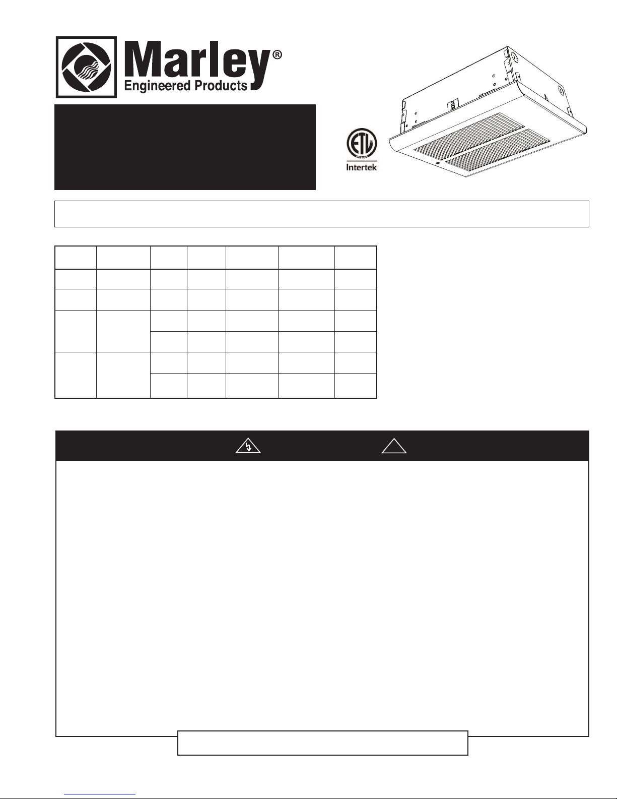
U Series
Fan Forced
Ceiling Mounted Heater
Conforms to ANSI/UL2021
and CSA C22.2 No. 46.
Installation, Operation & Maintenance Instructions
Specifications
MODEL CATALOG WIRE
NO. NO. VOLTS AMPS WATTS BTU/HR SIZE
U1000FA QCH1101 120
U1500FA QCH1151 120
240
U2004FA QCH1202
208
277
U2007FA QCH1207
240
8.4 1000 3413
4.2 500 1706
12.5 1500 5120
6.25 750 2560
8.4 2000 6826
4.2 1000 3413
7.3 1500 5120
3.62 750 2560
7.2 2000 6826
3.6 1000 3413
6.3 1500 5120
3.1 750 2560
14AWG
12AWG
14AWG
14AWG
14AWG
14AWG
IMPORTANT INSTRUCTIONS
WARNING
!
WHEN USING ELECTRIC APPLIANCES, BASIC PRECAUTIONS SHOULD ALWAYS BE FOLLOWED TO REDUCE THE
RISK OF FIRE, ELECTRIC SHOCK, AND INJURY TO PERSONS, INCLUDING THE FOLLOWING:
1. Read all instructions before installing or using this heater.
2. This heater is hot when in use. To avoid burns, do not let
bare skin touch hot surfaces. Keep combustible materials,
such as furniture, pillows, bedding, papers, clothes, etc. and
curtains at least 3 feet (0.9 m) from the front of the heater.
3. Extreme caution is necessary when any heater is used by or
near children or invalids and whenever the heater is left
operating and unattended.
4. Do not operate any heater after it malfunctions. Disconnect
power at service panel and have heater inspected by a reputable electrician before using.
5. Do not use outdoors.
6. To disconnect heater, turn controls to off, and turn off power
to heater circuit at main disconnect panel.
7. Do not insert or allow foreign objects to enter any ventilation
or exhaust opening as this may cause an electric shock, fire,
or damage to the heater.
8. To prevent a possible fire, do not block air intake or exhaust
in any manner.
SAVE THESE INSTRUCTIONS
9. A heater has hot and arcing or sparking parts inside. Do not
use it in areas where gasoline, paint, or flammable liquids
are used or stored.
10. Use this heater only as described in this manual. Any other
use not recommended by the manufacturer may cause fire,
electric shock, or injury to persons.
11. This heater is provided with a red alarm light that will illuminate only if the heater has turned off as a result of overheating. If you see the light on, immediately turn the heater
off and inspect for any objects on or adjacent to the heater
that may have blocked the airflow or otherwise caused high
temperatures to have occurred. DO NOT OPERATE THE
HEATER WITH THE ALARM LIGHT ILLUMINATING.
12. This heater is intended for comfort heating applications and
not intended for use in special environments. Do not use in
damp or wet locations such as marine or greenhouse or in
areas where corrosive or chemical agents are present.
13. When installing, see INSTALLATION INSTRUCTIONS for
additional warnings and precautions.
14. For safe and efficient operation, and to extend the life of your
heater, keep your heater clean - See MAINTENANCE
INSTRUCTIONS.
PPD 41511 12/14 5200-11226-000
INSTALLATION
INSTRUCTIONS
To prevent a possible fire, injury to persons or damage to the
heater, adhere to the following:
1. Disconnect all power coming to heater at main service
panel before wiring or servicing.
2. All wiring procedures and connections must be in accordance with the National and Local Codes having jurisdiction and the heater must be grounded.
3. Power supply must enter back box through the knockout
behind the disconnect switch.
4. Verify the power supply voltage coming to heater matches
the ratings as shown on the heater nameplate.
CAUTION: ENERGIZING HEATER AT A VOLTAGE GREATER
THAN THE VOLTAGE PRINTED ON THE NAMEPLATE WILL
DAMAGE THE HEATER AND VOID THE WARRANTY AND
COULD CAUSE A FIRE.
5. CAUTION - High temperature, risk of fire, keep electrical
cords, drapery, furnishings, and other combustibles at least
3 feet (0.9 m) from front of heater. Do not install heater
behind doors, below towel racks, or in an area where it is
subject to being blocked by furniture, curtains or storage
materials. Hot air from the heater may damage certain fabrics and plastics.
6. To reduce the risk of fire, do not store or use gasoline or
other flammable vapors and liquids in the vicinity of the
heater.
7. This heater is to be mounted only using back box. Back box
must be securely mounted to the building structure. Building
structure must be capable of supporting the heater and all
accessories (approximately 18 lbs (8.2 kg)).
This heater is intended for ceiling installation only. DO NOT install
8.
heater closer than 6 feet (1829 mm) from the floor. DO NOT install
closer than 12” (305 mm) to adjacent walls. DO NOT install in walls,
floor, or other locations.
9. Do not operate the heater without the grille installed.
10. Do not use this heater for dry out as the paint, plaster, sawdust and drywall sanding dust will permanently damage the
heater and must be kept out of the heater.
GENERAL
The heater is designed for recessed installation in 2” X 4” (50mm
X 101mm) joist or larger ceiling section using the back box provided. The heater may also be surface mounted by using the
Surface Mounting Frame. The heater is intended to be controlled by a single pole, wall mounted thermostat (ordered separately). The heater may be wired with standard building wire
(60°C). (See Fan Delay Notice Above). Refer to specification
chart (see pg. 4) for correct supply voltage and wire size.
NOTE: The optimum mounting height for this heater is 8’
(2440mm) from floor to bottom of back box. In any case do not
install closer than 6’ (1830mm) from the floor, or closer than 12”
(305mm) to adjacent walls.
INSTALLATION OF BACK BOX IN NEW CONSTRUCTION
NOTE: If the finished ceiling surface is already up, follow
instructions for “INSTALLATION OF BACK BOX IN EXISTING
CONSTRUCTION”.
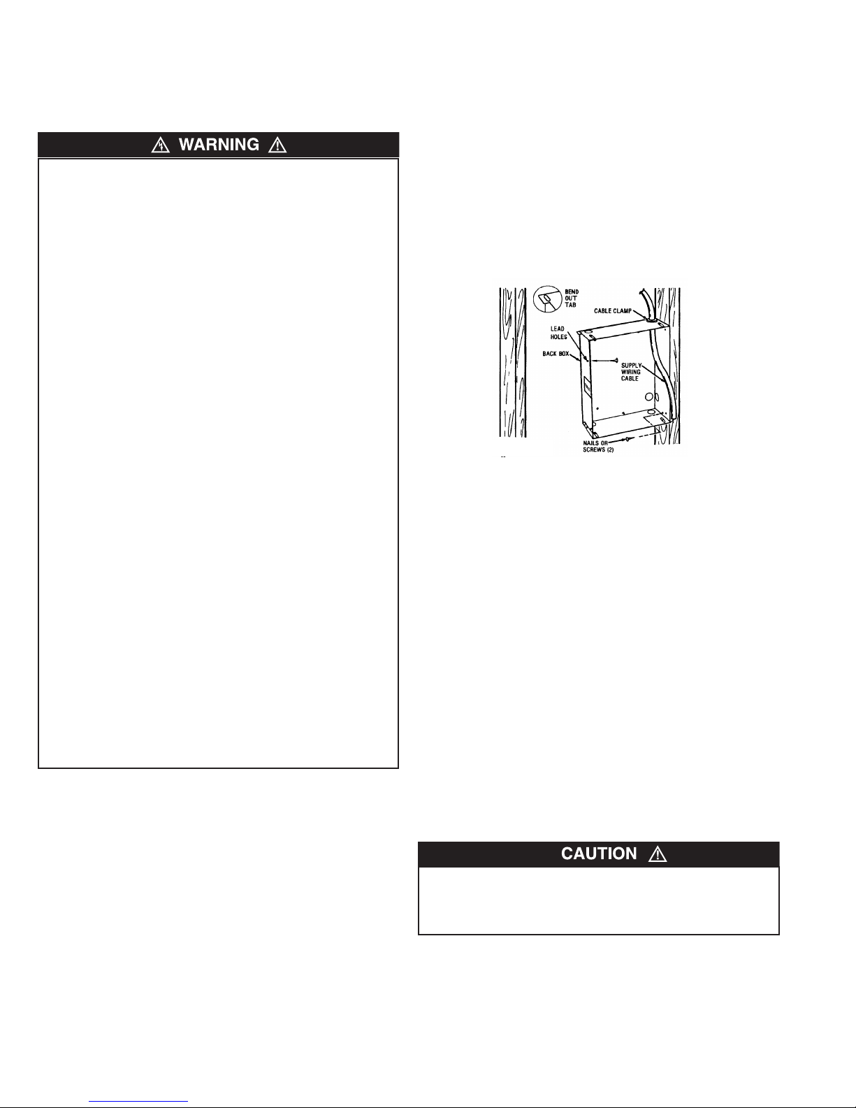
1. Determine which side of the back box is to be mounted
against a joist and bend the tabs at the rear corners out 90
degrees so that the back box will be square with the joist
after installation. (See Figure 1).
2. Remove one of the knockouts on socket side of the back box
and install a cable or conduit connector.
3. Position back box against side of joist and secure using
nails or screws as shown in Figure 1.
Ceiling joist
Figure 1
NOTE: The back box must be installed with the front edge flush
with the finished surface.
4. Run power supply cable through the connector, leaving about
8” (203mm)of wire inside the box.
5. Run thermostat cable from wall thermostat to heater location
leaving at least 6” (153mm) of cable inside the box. (See
Fan Delay Notice.)
6. Connect the supply cable ground wire to green ground screw
provided.
NOTE: Lead holes for a #8 sheet metal screw have been provided in the sides of the back box. After the finished ceiling has
been put up, drive a # 8(m4) sheet metal screw (recommended
1”) through the side of the box not mounted to the joist. This will
prevent the back box from pulling out when installing the heater
assembly. (See Figure 1)
Installation of Back Box in Existing Construction
1. Carefully mark and cut a hole measuring 9-3/8" (235mm)
wide by 11-1/8" (283mm) long. One edge of the hole must be
cut along the edge of a joist.
2. Proceed to No. 1 through 6 (Installation of Back Box in New
Construction).
AN ELECTRICAL SHOCK, FIRE, OR WATER DAMAGE
COULD RESULT IF WIRING OR PIPING IS DAMAGED DURING CUTTING. MAKE SURE ALL WIRING AND PIPING ARE
CLEAR OF AREA BEFORE CUTTING.
2
Installation of Heater in T-Bar Ceiling
1
2
3
4
1
2
3
4
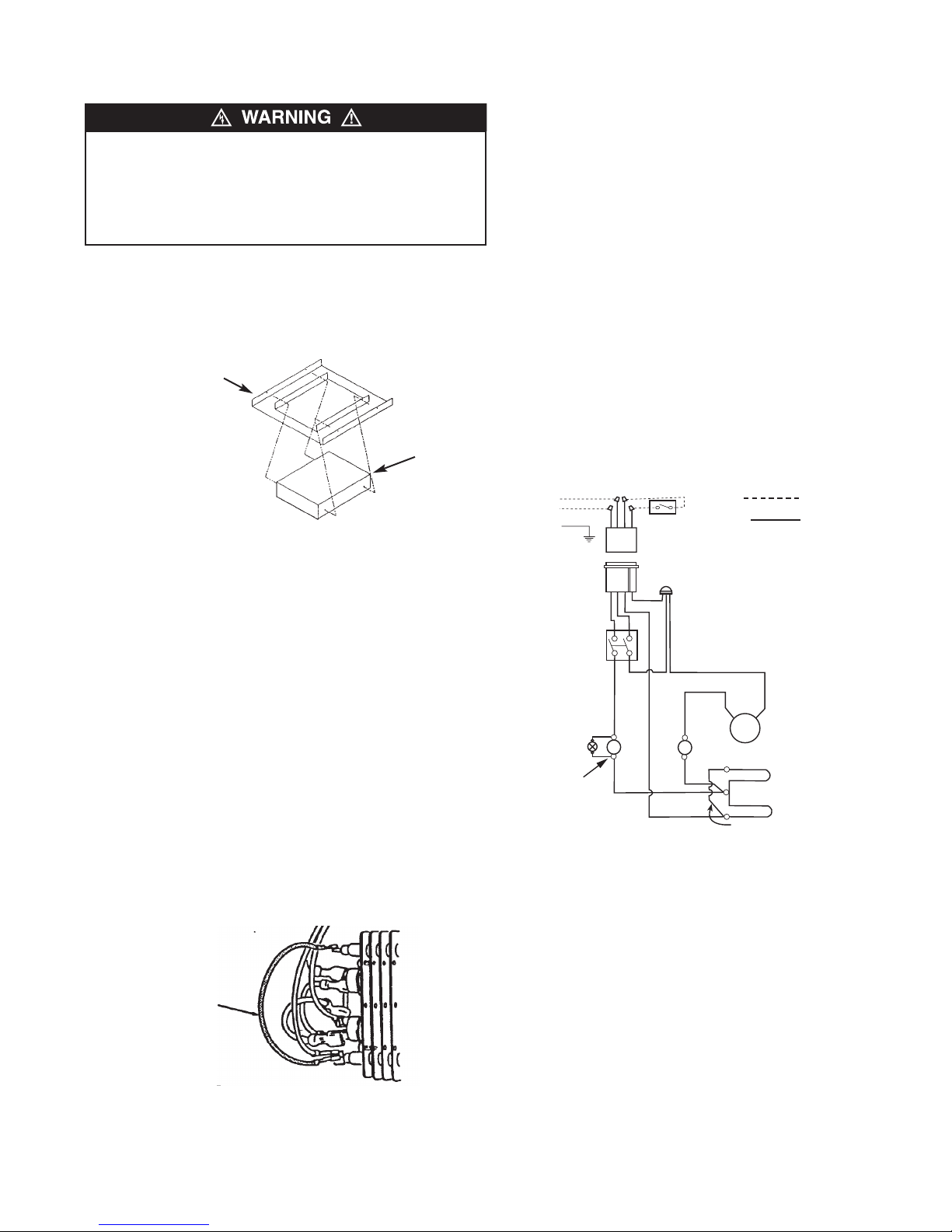
Disconnect
Switch
Assembly
OverTemperature
Limit
Fan Delay Control
Elements
Fan Motor
Red Jumper
(Remove for half wattage)
L1
L2
Tstat leads (Red)
G
Power leads
(Black & White)
Alarm
Light
Using Frame Kit Model HTBF
RISK OF FALLING – THE HEATER BACKBOX MUST BE
SECURELY MOUNTED TO THE BUILDING STRUCTURE AND
THE BUILDING STRUCTURE MUST BE CAPABLE OF SUPPORTING THE HEATER WITH ALL ACCESSORIES. THE
HEATER WEIGHT WITH ACCESSORIES IS AT LEAST 18 LBS
(18.2 KG).
1. Determine the desired location for the heater.
2. Remove heater from carton, remove front cover, heater
assembly from back box.
3. Remove T-Bar frame, envelope containing mounting screws
from carton.
HTBF Frame
Back box
Wiring of Heater
1. Following wiring diagram (Figure 4) connect supply wiring
and thermostat wiring to heater lead wires in back box.
NOTE: For 120 and 277 volt heaters connect the white neutral
supply lead to the heaters white pigtail lead, and connect the
black supply lead to the heaters black pigtail lead. For 208 and
240 volt heaters change the color of the heaters white pigtail
lead to black by wrapping with black electrical tape. (Most electrical codes require the supply leads to be conneced to black
leads). Then connect the two black supply leads to the two
black receptacle leads. Connect the two red thermostat leads to
thermostat as shown in wiring diagram.
2. Insert wiring plug from heater/fan assembly into socket in
back box.
3. Fit heater/fan assembly into back box and secure in place
with (2) screws provided through the center slots in the fan
assembly.
NOTE: Use the screws provided by the factory to install
heater/fan assembly to the back box.
4. Turn disconnect switch mounted on heater/fan assembly
“ON”.
Figure 2
4. Mount the heater backbox to the HTBF kit frame using the
four screws provided. Refer to figure 2.
5. Place the HTBF frame with heater backbox installed in ceiling framing and secure in position. Secure the frame to the
building structure as necessary using appropriate wire to pre
vent the heater and frame from falling.
6. Bring power supply cable to heater location. Remove the
desired knockout in backbox and install cable using an
appropriate cable clamp, leaving at least six inches (153mm)
of wire in box for connections.
NOTE: Power supply cable must enter backbox in location
behind the disconnect switch assembly.
7. Complete the installation by following the steps in the "Wiring
of heater" and "Installation of Front Cover(Grille)" sections."
Field Conversion for Lower Wattage
NOTE: Refer to specification chart for lower wattage ratings
which are available.
To convert heater to lower wattage rating, completely remove red
jumper wire from both heating elements (See Figure 3). Discard
this jumper. Be sure remaining wires are securely connected.
Remove red jumper
for lower wattage
rating
Figure 3
FIELD WIRING
FACTORY WIRING
Figure 4 - Wiring Diagram
INSTALLATION OF FRONT COVER (GRILLE)
1. Mount grille over brackets at the top of the heater. Sheet
metal tabs at the top end of the grille hook onto the brackets
at the top end of the heater’s fan panel assembly.
2. Insert screw through bottom hole on the grille. The screw with
thread into the backbox. Tighten the screw until the grille is
flush to the ceiling or mounting frame. BE CAREFUL NOT TO
OVER TIGHTEN.
3
OPERATING
MAINTENANCE
INSTRUCTIONS
1. Heater must be properly installed before operation.
2. Rotate wall thermostat knob counterclockwise until control
stops. This is the minimum heat setting.
3. Turn power supply to heater “ON” at main switch panel.
4. Heater should not operate. If it operates, disconnect power
and re-check wiring.
5. Rotate wall thermostat knob clockwise until it stops (maximum heat setting) and wait at least 2 minutes. Fan control
will delay fan coming on until element is warm.
6. If heater and fan do not come on, disconnect power and
check wiring.
7. Allow heater to continue to operate until room temperature
reaches desired comfort level. Then rotate wall thermostat
knob counterclockwise slowly until thermostat clicks off. Fan
must continue to operate for a minute or so until element
cools. If fan turns off immediately when thermostat is turned
off, disconnect power and check wiring. (See Fan Delay
Notice).
8. It may be necessary to readjust thermostat a time or so until
exact comfort level is attained. Rotation in the clockwise
direction will increase the amount of time the heater will produce heat. Rotation in the counterclockwise direction will
reduce the amount of time the heater is on.
NOTE: For best results, the heater should be left “ON” constantly during the heating season as the thermostat, when properly
set, will maintain the desired temperature. In the full counterclockwise position the heater will remain off until the room temperature drops well below freezing.
Operational Notice:
Your heater is equipped with an automatic reset over-temperature limit control that will automatically turn the heater off to prevent a fire if the heater overheats. If heater cycles off on this control, a red alarm light will illuminate.
INSTRUCTIONS
It is important to keep this heater clean. Your heater will give you
years of service and comfort with only minimum care. To assure
efficient operation follow the simple instructions below.
ALL SERVICING BEYOND SIMPLE CLEANING THAT
REQUIRES DISASSEMBLY SHOULD BE PERFORMED BY
QUALIFIED SERVICE PERSONNEL.
TO REDUCE RISK OF FIRE AND ELECTRIC SHOCK OR
INJURY, DISCONNECT ALL POWER COMING TO HEATER
AT MAIN SERVICE PANEL AND CHECK THAT THE ELEMENT
IS COOL BEFORE SERVICING OR PERFORMING
MAINTENANCE.
User Cleaning Instructions:
1. After the heater has cooled, a vacuum cleaner with brush
attachment may be used to remove dust and lint from exterior
surfaces of the heater including the grille openings.
2. With a damp cloth, wipe dust and lint from grille and exterior
surfaces.
3. Return power to heater and check to make sure it is operating properly.
Maintenance Cleaning Instructions:
(To be performed only by Qualified Service Personnel)
At least annually, the heater should be cleaned and serviced by
a qualified service person to assure safe and efficient operation.
This should include the removal of the grille and, as necessary
the heater from the backbox to clean residue from the unit. After
completing the cleaning and servicing, the heater should be fully
reassembled and checked for proper operation.
DO NOT TAMPER WITH OR BYPASS ANY SAFETY LIMITS
INSIDE HEATER.
CAUTION - DO NOT CONTINUE TO ATTEMPT TO USE THE
HEATER IF THE SAFETY CONTROL REPEATEDLY OPERATES AFTER BEING RESET. TO DO SO COULD PERMANENTLY DAMAGE THE HEATER OR CREATE A FIRE OR
SAFETY HAZARD.
4
All products manufactured by Marley Engineered Products are warranted against defects in workmanship and materials for one year from date of installation, except
LIMITED WARRANTY
heating elements which are warranted against defects in workmanship and materials for five years from date of installation. This warranty does not apply to damage from
accident, misuse, or alteration; nor where the connected voltage is more than 5% above the nameplate voltage; nor to equipment improperly installed or wired or
maintained in violation of the product’s installation instructions. All claims for warranty work must be accompanied by proof of the date of installation.
The customer shall be responsible for all costs incurred in the removal or reinstallation of products, including labor costs, and shipping costs incurred to return products to
Marley Engineered Products Service Center. Within the limitations of this warranty, inoperative units should be returned to the nearest Marley authorized service center
or the Marley Engineered Products Service Center, and we will repair or replace, at our option, at no charge to you with return freight paid by Marley. It is agreed that such
repair or replacement is the exclusive remedy available from Marley Engineered Products.
THE ABOVE WARRANTIES ARE IN LIEU OF ALL OTHER WARRANTIES EXPRESSED OR IMPLIED, AND ALL IMPLIED WARRANTIES OF MERCHANTABILITY AND
FITNESS FOR A PARTICULAR PURPOSE WHICH EXCEED THE AFORESAID EXPRESSED WARRANTIES ARE HEREBY DISCLAIMED AND EXCLUDED FROM THIS
AGREEMENT. MARLEY ENGINEERED PRODUCTS SHALL NOT BE LIABLE FOR CONSEQUENTIAL DAMAGES ARISING WITH RESPECT TO THE
PRODUCT, WHETHER BASED UPON NEGLIGENCE, TORT, STRICT LIABILITY, OR CONTRACT.
Some states do not allow the exclusion or limitation of incidental or consequential damages, so the above exclusion or limitation may not apply to you. This warranty gives
you specific legal rights, and you may also have other rights which vary from state to state.
For the address of your nearest authorized service center, contact Marley Engineered Products in Bennettsville, SC, at 1-800-642-4328. Merchandise returned to the fac-
tory must be accompanied by a return authorization and service identification tag, both available from Marley Engineered Products. When requesting return authorization,
include all catalog numbers shown on the products.
HOW TO OBTAIN WARRANTY SERVICE AND
WARRANTY PARTS PLUS GENERAL INFORMATION
1. Warranty Service or Parts 1-800-642-4328
2. Purchase Replacement Parts 1-800-654-3545
3. General Product Information www.marleymep.com
Note: When obtaining service always have the following:
1. Model number of the product
2. Date of manufacture
3. Part number or description
470 Beauty Spot Rd. East
Bennettsville, SC 29512 USA
 Loading...