

Page 1
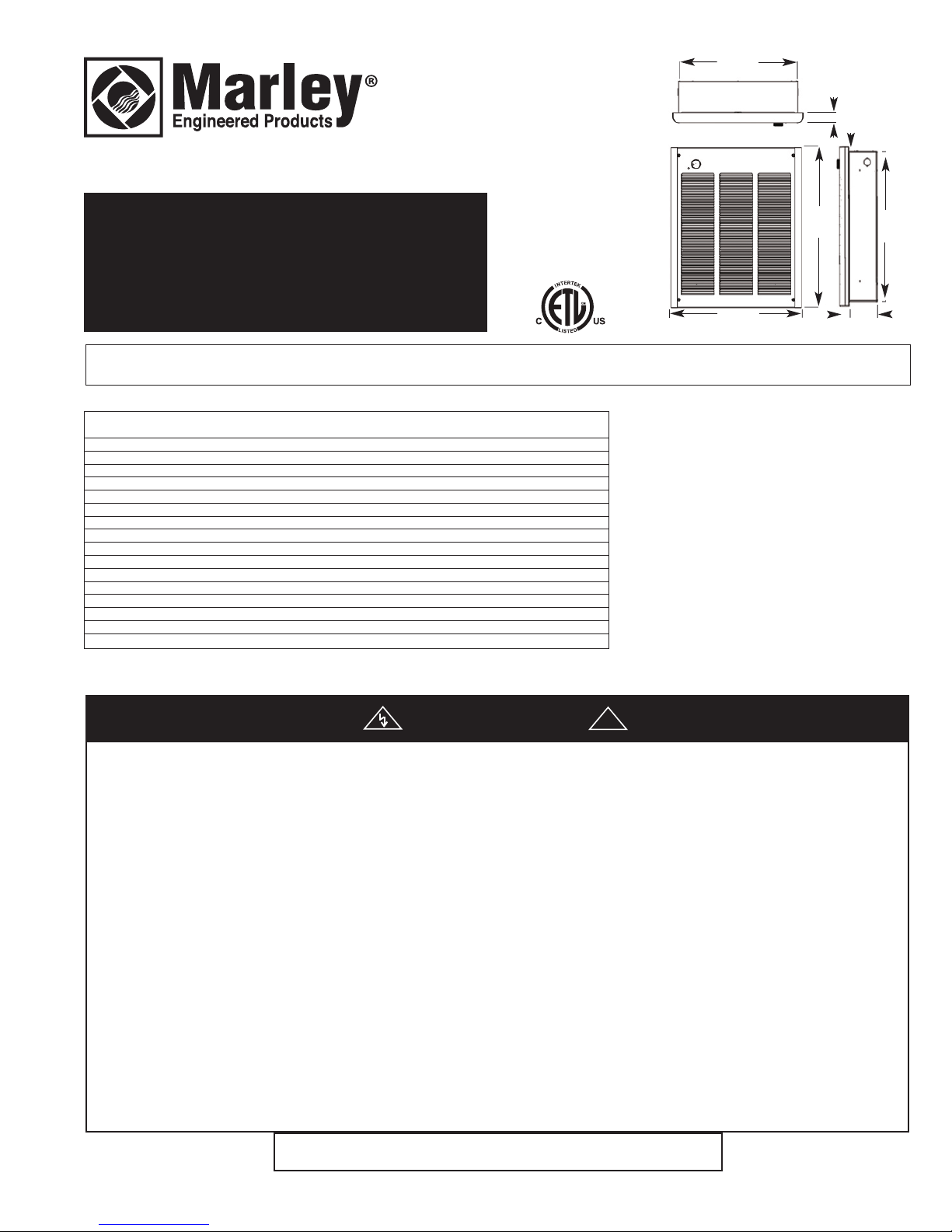
14-5/16”
3
64 mm
1
-3/8”
35 mm
1-1/2”
39 mm
K Series
Fan Forced
Wall Heaters
Installation, Operation & Maintenance Instructions
Specifications
ODEL SHIP WT.
M
NUMBER VOLTAGE WATTAGE PHASE CFM AMPS (LBS.)
151FC 120 1500 1 100 12.5 22
K
K204FC 240/208 2000/1500 1 100 8.3/7.3 22
K303FC 347 3000 1 100 8.6 25
K304FC 240 3000 1 100 12.5 22
306FC 600 3000 3 100 5.0 25
K
K404FC 240/208 4000/3000 1 100 16.7/14.4 22
K403FC 347 4000 1 100 11.5 25
K406FC 600 4000 3 100 6.7 25
K408FC 208V 4000 1 100 19.2 22
K483FC 347 4800 1 100 13.8 25
K484FC 240/208 4800/3600 1 100 20.9/17.3 22
K486FC 600 4800 3 100 8 25
K4083FC 208V 4000 3 100 11.1 23
K487FC 277V/240 4800/3600 1 100 17.3 23
K488FC 208V 4800 1 100 23.1 23
K4883FC 208V 4800 3 100 13.3 23
15-3/4”
400 mm
19-1/8”
86
4
mm
3-7/8”
99 mm
18-1/4”
464
mm
IMPORTANT INSTRUCTIONS
WARNING
WHEN USING ELECTRIC APPLIANCES, BASIC
PRECAUTIONS SHOULD ALWAYS BE FOLLOWED TO
REDUCE THE RISK OF FIRE, ELECTRIC SHOCK, AND
INJURY TO PERSONS, INCLUDING THE FOLLOWING:
1. Read all instructions before installing or using this heater.
2. This heater is hot when in use. To avoid burns, do not let
bare skin touch hot surfaces. Keep combustible materials,
such as furniture, pillows, bedding, papers, clothes, etc. and
curtains at least 3 feet (0.9 m) from the front of the heater.
3. Extreme caution is necessary when any heater is used by or
near children or invalids and whenever the heater is left
operating and unattended.
4. Do not operate any heater after it malfunctions. Disconnect
power at service panel and have heater inspected by a
reputable electrician before using.
5. Do not use outdoors.
6. To disconnect heater, turn controls to OFF, and turn off
power to heater circuit at main disconnect panel.
7. Do not insert or allow foreign objects to enter any ventilation
or exhaust opening as this may cause an electric shock, fire,
or damage to the heater.
!
8. To prevent a possible fire, do not block air intake or exhaust
in any manner.
9. A heater has hot and arcing or sparking parts inside. Do not
use it in areas where gasoline, paint, or flammable liquids
are used or stored.
10. Use this heater only as described in this manual. Any other
use not recommended by the manufacturer may cause fire,
electric shock, or injury to persons.
11. This heater is intended for comfort heating applications and
not intended for use in special environments. Do not use in
damp or wet locations such as marine or greenhouse or in
areas where corrosive or chemical agents are present.
12. When installing, see INSTALLATION INSTRUCTIONS for
additional warnings and precautions.
13. For safe and efficient operation, and to extend the life of your
heater, keep your heater clean - See MAINTENANCE
INSTRUCTIONS.
SAVE THESE INSTRUCTIONS
PPD 41511 7/14 5200-11210-000 (ISS 1.0)
Page 2
INSTALLATION
INSTRUCTIONS
To prevent a possible fire, injury to persons or damage to the
heater, adhere to the following:
1. Disconnect all power coming to heater at main service
panel before wiring or servicing.
2. All wiring procedures and connections must be in
accordance with the National and Local Codes having
jurisdiction and the heater must be grounded.
3. Power supply must enter back box through the knockouts.
See also TOP marking on the back box for proper
orientation.
4. Verify the power supply voltage coming to heater matches
the ratings as shown on the heater nameplate.
CAUTION: ENERGIZING HEATER AT A VOLTAGE GREATER
THAN THE VOLTAGE PRINTED ON THE NAMEPLATE WILL
DAMAGE THE HEATER AND VOID THE WARRANTY AND
COULD CAUSE A FIRE.
5. CAUTION - High temperature, risk of fire, keep electrical
cords, drapery, furnishings, and other combustibles at least
3 feet (0.9 m) from front of heater. Do not install heater
behind doors, below towel racks, in the ceiling, or in an area
where it is subject to being blocked by furniture, curtains or
storage materials. Hot air from the heater may damage certain fabrics and plastics.
6. To reduce the risk of fire, do not store or use gasoline or
other flammable vapors and liquids in the vicinity of the
heater.
7. This heater is to be mounted only using back box and may
be installed with the back box recessed or surface mounted
as described within this manual.
8. The following minimum clearances must be maintained:
Bottom of heater to floor - 8” (203 mm) - optimum height
is 18” to 24”.
Sides of heater to adjacent wall - 8” (203 mm) optimum minimum 12” (305 mm).
Top of heater to ceiling - 36” (915 mm).
9. Do not operate the heater without the grille installed.
10. Do not use this heater for dry out as the paint, plaster,
sawdust and drywall sanding dust will permanently damage
the heater and must be kept out of the heater.
GROUND
SCREW
BACK BOX
” MIN.
8
(203mm)
CABLE
LAMP
C
POWER SUPPLY CABLE
” MIN.
8
(203mm)
AIL OR SCREW
N
(2 EACH SIDE)
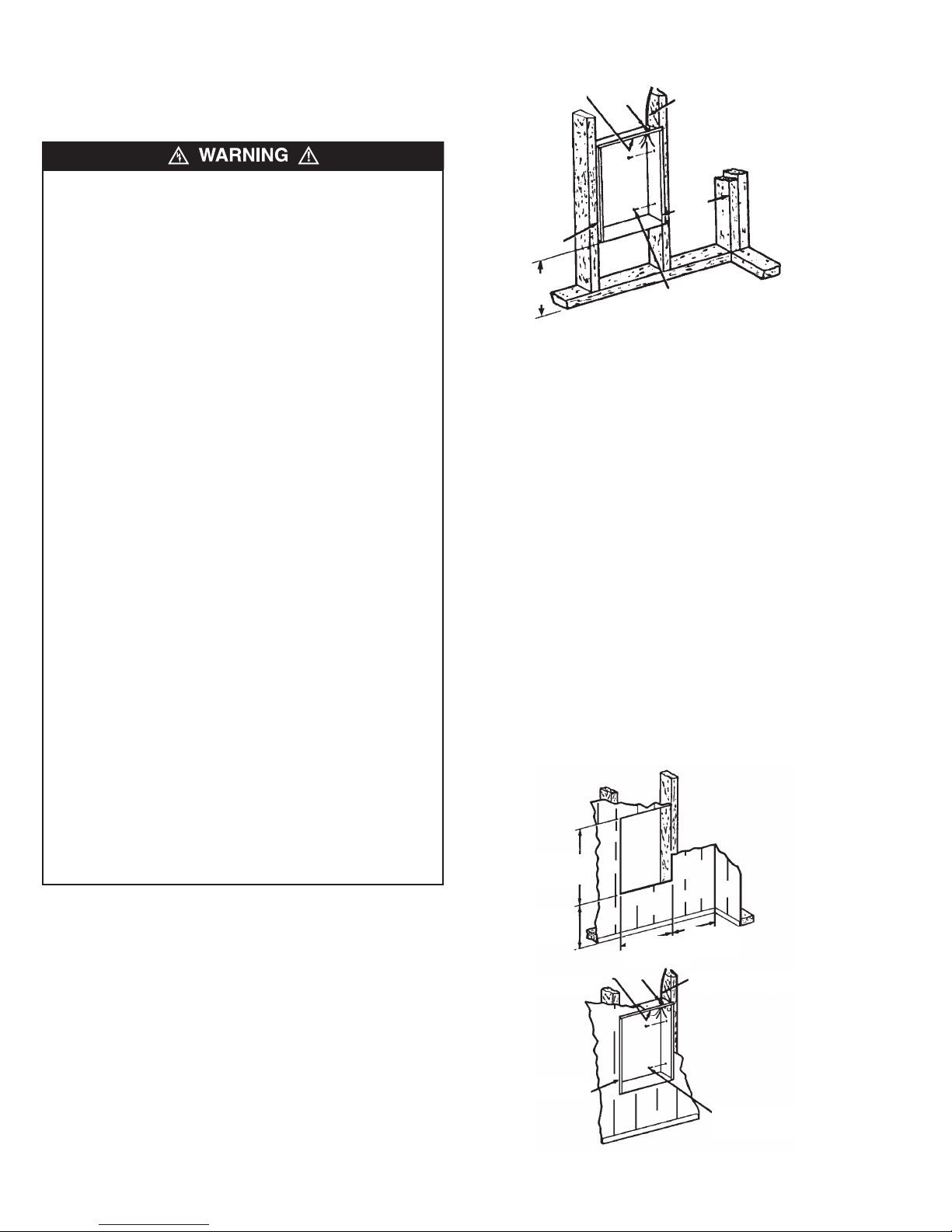
Figure 1: Locating Recessed Back Box in New Construction
NOTE: Wire compartment volume - 119 in
3
(1950 cm3).
a. Run a power supply cable into the knockout area in the
upper right hand corner of the back box. All wiring must be
in accordance with National and Local Electrical Codes.
Refer to Specifications, page 1 for correct wire size.
b. Remove knockout in the top of the back box and install a
cable clamp.
c. Insert power supply cable through cable clamp, allowing at
least 6" (152 mm) of leads to extend inside the back box.
d. Ground the back box by connecting the supply ground
lead wire to the green ground screw located in the inside
top of the back box.
Installation of Back Box in Existing Construction
1. Provide a wall opening 14-1/2" (362 mm) wide by 18-1/2"
(470 mm) high at the desired mounting height, but no closer
than 8" (203 mm) to adjacent wall or floor. (see Figure 2.)
NOTE: Locate so at least one side of opening is at wall stud.
2. Power Supply Wiring
NOTE: Wiring Compartment Volume - 119 in3 (1950 cm3).
18-1/2” MIN.
(470mm)
Installation of Back Box in New Construction
1. Mounting Back Box (see Figure 1).
a. Place the back box between two 16" (406 mm) center-
to-center wall studs at the desired mounting height but
no closer than 8" (203 mm) to adjacent wall or floor.
NOTE: If wall studs are spaced greater than 16” on center, additional framing supports may be necessary.
b. Align back box such that the bottom and sides will be
flush with finished wall surface (top flange of back box
should protrude approximately 1/2" (12.7 mm) from finished wall surface).
c. Secure the back box in position with wood screws or
nails as shown in Figure 1.
2. Power Supply Wiring (see Figure 1)
8” MIN.
(203mm)
CABLE CLAMP
GROUND SCREW
BACK BOX
14-1/2” MIN.
(362mm)
8” MIN.
(203mm)
POWER SUPPLY CABLE
NAIL OR SCREW
(2 EACH SIDE)
Figure 2: Locating Recessed Back Box in Existing Construction
2
Page 3
a. Run a power supply cable into the area above the top of
the wall opening. All wiring must be in accordance with
National and Local electrical codes. Refer to Table 1,
page 1 for correct wire size.
b. Install a cable clamp in the knockout in the top of back
box.
c. Insert power supply cable through cable clamp, allowing at
least 6" (152mm) of cable length to remain inside the back
box to facilitate connections.
d. Ground the back box by connecting the supply ground wire
to the green ground screw located in the inside top of the
back box.
3. Mounting Back Box
a. Place the back box into wall opening flush with finished
wall surface on bottom and sides of box. (Top flange of
back box should protrude approximately 1/2" (12.7mm)
from finished wall surface).
b. Secure the back box in place with wood screws or nails.
(Optional) Installation of Back Box With
Surface-Mounting Frame (see Figure 3).
1. Secure back box to wall (with knockouts in upper right
hand corner) using screws and anchors.
2. Hang the surface-mounting frame on the back box.
Ensure that the back edge of the surface-mounting
frame is flush against the wall.
3-13/16"
(97mm)
MOUNT BACK BOX TO
WALL USING REAR
MOUNTING HOLES.
HANG FRAME
ON BACK BOX
15-5/32"
(385mm)
Figure 3: Surface Mounting Installation
NOTE: If heater is located in a high traffic area where it may be
subjected to vandalism or abuse, take extreme care to see that
the box is firmly attached to the wall.
3. Power Supply Wiring
NOTE: Wiring Compartment Volume - 119"3 (1950cm3).
a. Run a power supply cable into the area of the upper right
corner of the mounting frame. All wiring must be in accordance to National and local Electrical Codes. Refer to
Table 1 for proper wire sizes.
NOTE: If the wiring is to run through the wall, cut a hole in the
wall near the top of the back box. Run the supply wire through
this hole. Then remove the knockout from the top of the box and
proceed to step c.
b. Remove the knockout on the top side of the frame.
c. Feed the power supply cable through the frame allowing 6"
(152mm) of lead to remain inside the frame
d. Secure the power supply cable to the back box (using
cable clamps, connector, or other suitable strain relief)
allowing 6”(152mm) of lead to remain inside the inner
housing.
19"
(482mm)
e. Ground the back box by connecting the supply ground
leadwire to the green ground screw located in the inside
top of the back box.
Installation of Heater Assembly and Grille
After back box is completely installed and no further construction
dirt is expected, clean debris from back box, remove heater
assembly from its carton, then refer to Figure 4 and proceed as
follows:
1. Insert the heater assembly into back box, placing the four
mounting holes (with key-hole slots) over the screws in the
back box. Tighten all screws securely.
NOB
THERMOSTAT
RECESS BACK
BOX
HEATER
ASSEMBLY
Figure 4
2. If surface-mounting frame is used, ensure that the frame is
even with all four heater assembly tabs before tightening
screws.
3. Connect the lead wires from the disconnect switch to the
lead wires from the fan deck. (see wiring diagrams)
After connection, push wires back into opening.
4. Turn thermostat to the extreme counterclockwise position.
5. Mount the grille using four (4) long screws provided. The
screws thread into holes located in the side flanges of the
back box.
6. Push thermostat knob onto thermostat shaft.
1500, 4800, 4000, & 3000 WATT HEATERS
120V, 208V, 240V, OR 277V (Full wattage heaters can be
converted to half wattage by removing the red jumper wire
connecting the top and bottom element terminals.)
NOTE: Conversion not applicable on K151FC.
K
GRILLE
3
Page 4
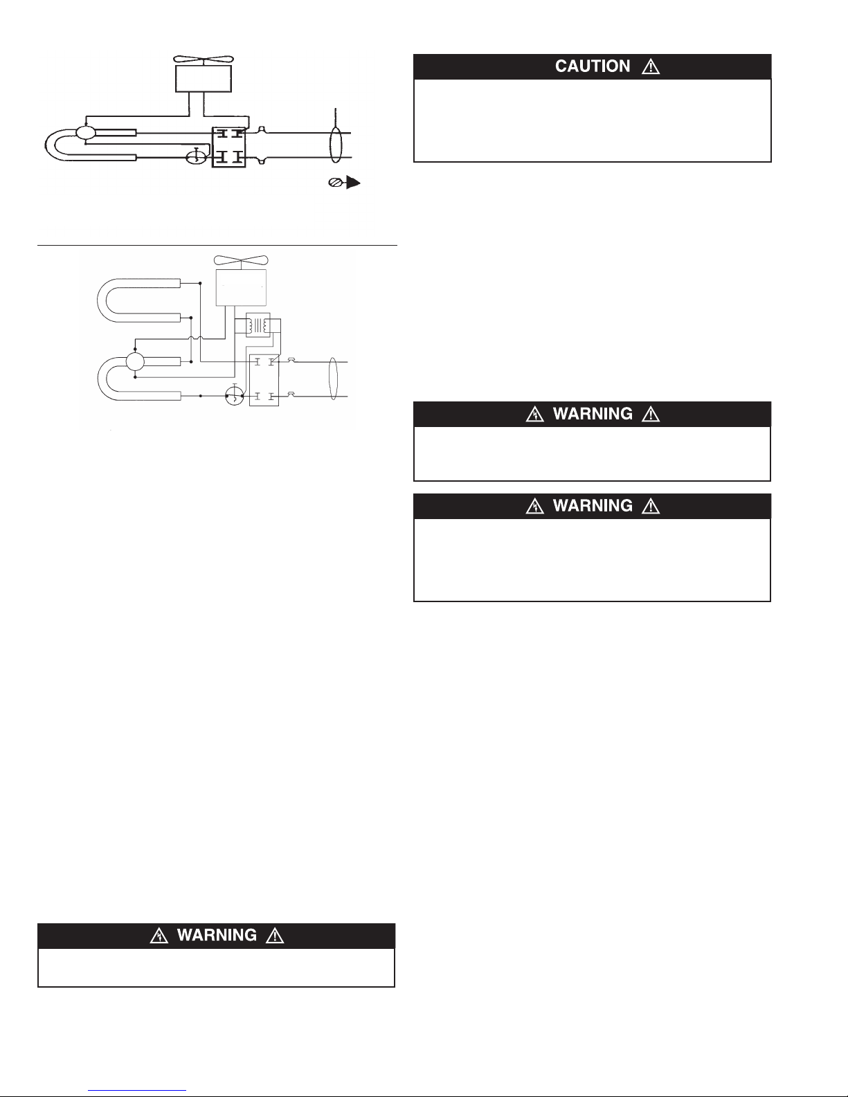
F.D.
Element
2000 & 1500 WATT HEATERS
208V, 240V, OR 277V
Manual Reset
Limit
an Motor
F
T
’Stat
G
Wiring
ND
ield
F
CAUTION - DO NOT CONTINUE TO ATTEMPT TO USE THE
HEATER IF THE SAFETY CONTROL REPEATEDLY OPERATES AFTER BEING RESET. TO DO SO COULD PERMANENTLY DAMAGE THE HEATER OR CREATE A FIRE OR
SAFETY HAZARD.
Special Note: In addition to the over-temperature safety control,
this heater is provided with a back-up thermal fuse (one shot)
that will permanently shut the heater off if for some reason the
over-temperature safety control should not function as intended.
If this thermal fuse activates, the heater will not reset and must
be repaired by a qualified repair person.
Fan Motor
Element
F.D.
lement
E
4800, 4000, & 3000 WATT HEATERS
347V, 600V
Manual Reset
T’Stat
Limit
OPERATING
INSTRUCTIONS
1. Heater must be properly installed before operation.
2. Turn power to heater on at main switch panel. Rotate the
thermostat knob fully clockwise. This should energize the
heating elements and the fan, causing air to flow from the air
discharge at the openings in the bottom of the grille.
3. After the discharge air has become warm, rotate the thermostat knob to the desired position to obtain room comfort.
NOTE: For best results, the heater should be left “ON” constantly during the heating season as the thermostat, when properly
set, will maintain the desired temperature. In the full counterclockwise position the heater will remain off until the room temperature drops well below freezing.
How To Reset Over -Temperature Safety Control:
Your heater is equipped with a manual reset thermal limit safety
control that will automatically turn the heater off to prevent a fire
if the heater overheats. This control is located on the fan panel
assembly between the element and fan blade and marked
“RESET”. The red reset button can be seen through the front
grille when the heater is installed. To reset, allow the heater to
cool, then push the red button that is visible through the hole in
the fan panel. The heater should immediately return to normal
operation.
MAINTENANCE
INSTRUCTIONS
It is important to keep this heater clean. Your heater will give you
years of service and comfort with only minimum care. To assure
efficient operation follow the simple instructions below.
ALL SERVICING BEYOND SIMPLE CLEANING THAT
REQUIRES DISASSEMBLY SHOULD BE PERFORMED BY
QUALIFIED SERVICE PERSONNEL.
TO REDUCE RISK OF FIRE AND ELECTRIC SHOCK OR
INJURY, DISCONNECT ALL POWER COMING TO HEATER
AT MAIN SERVICE PANEL AND CHECK THAT THE ELEMENT
IS COOL BEFORE SERVICING OR PERFORMING
MAINTENANCE.
User Cleaning Instructions:
1. After the heater has cooled, a vacuum cleaner with brush
attachment may be used to remove dust and lint from exterior
surfaces of the heater including the grille openings.
2. With a damp cloth, wipe dust and lint from grille and exterior
surfaces.
3. Return power to heater and check to make sure it is operating properly.
Maintenance Cleaning Instructions:
(To be performed only by Qualified Service Personnel)
At least annually, the heater should be cleaned and serviced by
a qualified service person to assure safe and efficient operation.
This should include the removal of the grille and, as necessary
the heater from the backbox to clean residue from the unit. After
completing the cleaning and servicing, the heater should be fully
reassembled and checked for proper operation.
DO NOT TAMPER WITH OR BYPASS ANY SAFETY LIMITS
INSIDE HEATER.
4
Page 5
All products manufactured by Marley Engineered Products are warranted against defects in workmanship and materials for one year from date of installation, except
LIMITED WARRANTY
heating elements which are warranted against defects in workmanship and materials for five years from date of installation. This warranty does not apply to damage from
accident, misuse, or alteration; nor where the connected voltage is more than 5% above the nameplate voltage; nor to equipment improperly installed or wired or
maintained in violation of the product’s installation instructions. All claims for warranty work must be accompanied by proof of the date of installation.
The customer shall be responsible for all costs incurred in the removal or reinstallation of products, including labor costs, and shipping costs incurred to return products to
Marley Engineered Products Service Center. Within the limitations of this warranty, inoperative units should be returned to the nearest Marley authorized service center
or the Marley Engineered Products Service Center, and we will repair or replace, at our option, at no charge to you with return freight paid by Marley. It is agreed that such
repair or replacement is the exclusive remedy available from Marley Engineered Products.
THE ABOVE WARRANTIES ARE IN LIEU OF ALL OTHER WARRANTIES EXPRESSED OR IMPLIED, AND ALL IMPLIED WARRANTIES OF MERCHANTABILITY AND
FITNESS FOR A PARTICULAR PURPOSE WHICH EXCEED THE AFORESAID EXPRESSED WARRANTIES ARE HEREBY DISCLAIMED AND EXCLUDED FROM THIS
AGREEMENT. MARLEY ENGINEERED PRODUCTS SHALL NOT BE LIABLE FOR CONSEQUENTIAL DAMAGES ARISING WITH RESPECT TO THE
PRODUCT, WHETHER BASED UPON NEGLIGENCE, TORT, STRICT LIABILITY, OR CONTRACT.
Some states do not allow the exclusion or limitation of incidental or consequential damages, so the above exclusion or limitation may not apply to you. This warranty gives
you specific legal rights, and you may also have other rights which vary from state to state.
For the address of your nearest authorized service center, contact Marley Engineered Products in Bennettsville, SC, at 1-800-642-4328. Merchandise returned to the factory must be accompanied by a return authorization and service identification tag, both available from Marley Engineered Products. When requesting return authorization,
include all catalog numbers shown on the products.
HOW TO OBTAIN WARRANTY SERVICE AND
WARRANTY PARTS PLUS GENERAL INFORMATION
1. Warranty Service or Parts 1-800-642-4328
2. Purchase Replacement Parts 1-800-654-3545
3. General Product Information www.marleymep.com
Note: When obtaining service always have the following:
1. Model number of the product
2. Date of manufacture
3. Part number or description
470 Beauty Spot Rd. East
Bennettsville, SC 29512 USA
Page 6

Notes/Notas/Notes
6
Page 7

Serie K
Calefactores de pared
14-5/16”
64 mm
3
9-1/8”
1
486
-3/8”
1
35 mm
1
-1/2”
39 mm
18-1/4”
64
m
m
4
mm
con ventilador
15-3/4”
400 mm
3-7/8”
9
Instrucciones de instalación, operación y mantenimiento
Especificaciones
E MODELO VOLTAGE WATTAGE PHASE CFM AMPS SHIP WT. (LBS.)
D
K151FC 120 1500 1 100 12.5 22
K204FC 240/208 2000/1500 1 100 8.3/7.3 22
K303FC 347 3000 1 100 8.6 25
K304FC 240 3000 1 100 12.5 22
306FC 600 3000 3 100 5.0 25
K
K404FC 240/208 4000/3000 1 100 16.7/14.4 22
403FC 347 4000 1 100 11.5 25
K
K406FC 600 4000 3 100 6.7 25
K408FC 208V 4000 1 100 19.2 22
K483FC 347 4800 1 100 13.8 25
K484FC 240/208 4800/3600 1 100 20.9/17.3 22
K486FC 600 4800 3 100 8 25
K4083FC 208V 4000 3 100 11.1 23
K487FC 277V/240 4800/3600 1 100 17.3 23
K488FC 208V 4800 1 100 23.1 23
K4883FC 208V 4800 3 100 13.3 23
INSTRUCCIONES IMPORTANTES
ADVERTENCIA
AL UTILIZAR ARTEFACTOS ELÉCTRICOS, PARA
REDUCIR EL RIESGO DE INCENDIO, CHOQUE
ELÉCTRICO Y LESIONES PERSONALES DEBEN
OBSERVARSE SIEMPRE ALGUNAS PRECAUCIONES
BÁSICAS, COMO LAS SIGUIENTES:
1. Lea todas las instrucciones antes de instalar o utilizar este
calefactor.
2. Cuando está en funcionamiento, el calefactor está muy
caliente. Para evitar quemaduras, no deje que su piel haga
contacto directo con las superficies calientes. Mantenga los
materiales combustibles como muebles, almohadas, ropas
de cama, papeles, ropas, cortinas, etc. a 0.9 m (3 pies)
como mínimo del frente del calefactor.
3. Se necesita extremo cuidado al utilizar cualquier calefactor
junto a o cerca de niños o inválidos, y en todo momento en
que el calefactor quede funcionando y desatendido.
4. No opere ningún calefactor después de que haya tenido una
falla de funcionamiento. Desconecte la alimentación eléctrica en el tablero de servicio y haga revisar el calefactor por
un electricista calificado antes de usarlo.
5. No use el equipo en exteriores.
6. Para desconectar el calefactor, lleve los controles a la posición Apagado (OFF) y desconecte la alimentación del circuito del calefactor en el tablero de desconexión principal.
7. No inserte ni permita que entren objetos extraños en ninguna abertura de ventilación o de descarga, porque esto
puede ser causa de choque eléctrico, incendio o daño al
calefactor.
8. Para evitar un posible incendio, no bloquee de ningún modo
la entrada ni la descarga de aire.
9. Un calefactor tiene en su interior piezas calientes, y piezas
en donde se producen arcos o chispas. No lo utilice en
áreas en las que se utilice o almacene gasolina, pintura o
líquidos inflamables.
10. Utilice este calefactor únicamente de la manera descrita en
este manual. Cualquier otra forma de uso no recomendada
por el fabricante puede ser causa de incendio, choque eléctrico o daños personales.
11. Este calefactor está destinado a aplicaciones de calefacción
ambiental, y no es para utilizar en ambientes especiales. No
lo use en lugares húmedos o mojados como zonas marítimas o invernaderos, ni en áreas en las que estén presentes
agentes químicos o corrosivos.
12. Al realizar la instalación, vea las advertencias y precauciones adicionales en las INSTRUCCIONES DE INSTALACIÓN.
13. Para asegurar una operación segura y eficiente, y para
extender la vida útil de su calefactor, manténgalo limpio. Vea
las INSTRUCCIONES DE MANTENIMIENTO.
!
9 mm
GUARDE ESTAS INSTRUCCIONES
PPD 41511 7/14 5200-11210-000 (ISS 1.0)
Page 8

INSTRUCCIONES DE
INSTALACIÓN
Para evitar un posible incendio, lesiones personales o daños al cale-
factor, observe lo siguiente:
1. Antes de proceder a tareas de conexionado o de reparación del
calefactor, desconecte toda la alimentación eléctrica que llega al
mismo desde el tablero principal de servicio.
2. Todos los procedimientos de cableado y conexiones deben hacerse de conformidad con los códigos nacionales y locales que tengan jurisdicción, y el calefactor debe estar conectado a tierra.
3. La alimentación eléctrica debe ingresar a la caja posterior a través
de los prepunzonados. Verifique también la marca ARRIBA (TOP)
de la caja posterior para asegurar una orientación correcta.
4. Verifique que la tensión de alimentación provista al calefactor coincida con la tensión nominal indicada en la placa de características
del mismo.
ATENCIÓN: SI SE ENERGIZA UN CALEFACTOR CON UNA TENSIÓN MAYOR QUE EL VALOR DE TENSIÓN IMPRESO EN LA
PLACA DE CARACTERÍSTICAS, SE DAÑARÁ EL CALEFACTOR, SE
ANULARÁ LA GARANTÍA, Y PODRÍA PRODUCIRSE UN INCENDIO.
5. ATENCIÓN: alta temperatura, riesgo de incendio. Mantenga los
cables eléctricos, cortinados, muebles y otros elementos combustibles a 0.9 m (3 pies) como mínimo del frente del calefactor. No
instale el calefactor detrás de puertas, debajo de toalleros, en el
cielorraso, ni en un área en la que esté sujeto a bloqueo por muebles, cortinas o materiales almacenados. El aire caliente que sale
del calefactor puede dañar algunas telas y plásticos.
6. Para reducir el riesgo de incendio, no almacene ni use gasolina u
otros vapores y líquidos inflamables en las cercanías del calefactor.
7. Este calefactor debe montarse únicamente con la caja posterior, y
puede instalarse con la caja posterior empotrada o montada sobre
la superficie, como se describe en este manual.
8. Deben mantenerse las distancias mínimas que se indican a continuación:
Del fondo del calefactor al piso: 203 mm (8”); la altura
óptima es de 45.7 cm (18”) a 61.0 cm (24”).
De los costados del calefactor a la pared adyacente:
203 mm (8”); la distancia óptima es 305 mm (12”).
Del extremo superior del calefactor al cielorraso:
915 mm (36”).
9. No haga funcionar el calefactor sin haber instalado la rejilla.
10. No utilice este calefactor para fines de secado, ya que la pintura, el
yeso, el aserrín y el polvo proveniente del lijado de paredes secas
provocarán daños permanentes al calefactor, por lo que no deben
entrar al mismo.
ABRAZAD
RA PARA
TORNILLO DE
PUESTA A TIERRA
CAJA POSTERIOR
” MIN.
8
(203 mm)
E
CABLES
CABLE DE ALIMENTACIÓN
LÉCTRICA
E
” MIN.
8
(203 mm)
LAVO O TORNILLO
C
(2 DE CADA LADO)
Figura 1: Ubicación de la caja posterior empotrada en una construcción nueva
NOTA: Volumen del compartimiento de cables = 1950 cm
3
(119 pulgadas cúbicas)
a. Tienda un cable de alimentación eléctrica hacia el área de los
prepunzonados, en el ángulo superior derecho de la caja posterior. Todo el cableado debe hacerse de acuerdo con los códigos
eléctricos nacionales y locales. Vea los calibres correctos de
cables en Especificaciones, página 1.
b. Quite el prepunzonado de la cara superior de la caja posterior e
instale una abrazadera para cables.
c. Inserte el cable de alimentación eléctrica a través de la
abrazadera, dejando al menos 152 mm (6”) de cables de conexión para su extensión dentro del alojamiento.
d. Conecte a tierra la caja posterior, conectando el conductor de tier-
ra de la alimentación eléctrica al tornillo verde de puesta a tierra
ubicado en el interior de la cara superior de la caja posterior.
Instalación de la caja posterior en una construcción
existente
1. Practique en la pared una abertura de 362 mm (14-1/2”) de ancho
por 470 mm (18-1/2”) de alto, a la altura deseada para la instalación,
pero a no menos de 203 mm (8”) de la pared adyacente y del piso
(vea la Figura 2).
NOTA: elija la ubicación de modo que al menos un lado de la abertura
coincida con un travesaño de la pared.
2. Cableado de la fuente de alimentación
NOTA: volumen del compartimiento de cables = 1950 cm
(119 pulgadas cúbicas)
3
Instalación de la caja posterior en una construcción
nueva
1. Montaje de la caja posterior (vea la Figura 1).
a. Coloque la caja posterior entre dos travesaños de la pared
con una distancia entre centros de 406 mm (16”), a la altura
de montaje deseada, pero a no menos de 203 mm (8”) de una
pared adyacente y del piso.
NOTA: si los travesaños de la pared están espaciados más de 406 mm
(16”) entre centros, puede que se necesiten soportes de armazón adicionales.
b. Alinee la caja posterior de modo que la cara inferior y los
costados estén enrasados con la superficie de la pared terminada (el reborde superior de la caja posterior debe sobresalir
aproximadamente 12.7 mm [1/2”] de la superficie de la pared
terminada).
c. Asegure la caja posterior en su posición con tornillos para
madera o con clavos, como se muestra en la Figura 1.
2. Cableado de la fuente de alimentación (vea la Figura 1)
18-1/2” MIN.
(470 mm)
8” MIN.
(203 mm)
ABRAZADERA PARA CABLES
TORNILLO DE
PUESTA A TIERRA
CAJA POSTERIOR
Figura 2: Ubicación de la caja posterior empotrada en una
construcción existente
8
14-1/2” MIN.
(362 mm)
8” MIN.
(203 mm)
CABLE DE ALIMENTACIÓN
ELÉCTRICA
CLAVO O TORNILLO
(2 DE CADA LADO)
Page 9

a. Tienda un cable de alimentación eléctrica hacia el área que está
encima de la parte superior de la abertura de la pared. Todo el
cableado debe hacerse de acuerdo con los códigos eléctricos
nacionales y locales. Vea los calibres correctos de cables en la
Tabla 1 de la página 1.
b. Instale una abrazadera para cables en el prepunzonado situado
en la cara superior de la caja posterior.
c. Inserte el cable de alimentación eléctrica a través de la
abrazadera, dejando como mínimo 152 mm (6”) de longitud de
cable dentro de la caja, para facilitar las conexiones.
d. Conecte a tierra la caja posterior, conectando el cable de tierra de
la alimentación eléctrica al tornillo verde de puesta a tierra ubicado en el interior de la cara superior de la caja.
3. Montaje de la caja posterior
a. Coloque la caja posterior en la abertura de la pared, enrasada
con la superficie de la pared terminada en la cara inferior y los
costados de la caja. (El reborde superior de la caja posterior debe
sobresalir aproximadamente 12.7 mm [1/2”] de la superficie de la
pared terminada).
b. Asegure la caja posterior en su posición con tornillos para
madera o clavos.
(Opcional) Instalación de la caja posterior con el
Bastidor de Montaje Superficial (vea la Figura 3)
1. Asegure la caja posterior a la pared (con los prepunzonados en el
ángulo superior derecho) mediante tornillos y anclajes.
2. Ajuste el bastidor de montaje superficial en la caja posterior.
Asegúrese de que el borde posterior del bastidor de montaje superficial esté enrasado contra la pared.
3-13/16"
(97 mm)
e. Conecte a tierra la caja posterior, conectando el conductor de tier-
ra de la alimentación eléctrica al tornillo verde de puesta a tierra
ubicado en el interior de la cara superior de la caja.
Instalación del conjunto del calefactor y de la rejilla
Una vez que la caja posterior esté completamente instalada y no deba
producirse más suciedad de construcción, limpie los desperdicios de la
caja posterior, extraiga el conjunto del calefactor de su caja y continúe
como sigue, de acuerdo con la Figura 4:
ERILLA
P
REJILLA
CAJA POSTERIOR
EMPOTRADA
Figura 4
ERMOSTATO
T
ONJUNTO DE
C
CALEFACTOR
MONTE LA CAJA POSTERIOR EN LA PARED,
MEDIANTE LOS AGUJEROS DE MONTAJE
POSTERIORES.
AJUSTE EL BASTIDOR
EN LA CAJA POSTERIOR
15-5/32"
(385 mm)
19"
(482 mm)
Figura 3: Instalación de montaje superficial
NOTA: si el calefactor está ubicado en un sitio de alto tráfico, en el que
pueda estar sujeto a vandalismo o maltrato, tenga mucho cuidado de
verificar que la caja esté firmemente fijada a la pared.
3. Cableado de la fuente de alimentación
NOTA: volumen del compartimiento de cables = 1950 cm
(119 pulgadas cúbicas).
a. Tienda un cable de alimentación eléctrica hacia el área del ángu-
lo superior derecho del bastidor de montaje. Todo el cableado
debe hacerse de acuerdo con los códigos eléctricos nacionales y
locales. Vea los calibres correctos de cables en la Tabla 1.
NOTA: si el cableado debe pasar a través de la pared, corte un agujero
en la pared cerca de la cara superior de la caja posterior. Pase el cable
de alimentación eléctrica por este agujero. Luego extraiga el prepunzonado de la cara superior de la caja, y continúe con el paso c.
b. Extraiga el prepunzonado de la cara superior del bastidor.
c. Pase el cable de alimentación eléctrica a través del bastidor,
dejando 152 mm (6") de cable dentro del bastidor.
d. Asegure el cable de alimentación eléctrica a la caja posterior (use
abrazaderas o conector para cables, u otro alivio de tensiones
adecuado) dejando 152 mm (6”) de cable dentro del alojamiento
interior.
3
1. Inserte el conjunto de calefactor en la caja posterior, colocando los
cuatro agujeros de montaje (con ranuras tipo bocallave) sobre los
tornillos de la caja. Apriete firmemente todos los tornillos.
2. Si se utiliza el bastidor de montaje superficial, antes de apretar los
tornillos asegúrese de que el bastidor esté nivelado con las cuatro
lengüetas del conjunto de calefactor.
3. Conecte los cables de conexión del interruptor de desconexión a los
cables de conexión de la plataforma de ventilador (vea los diagramas de conexionado). Después de la conexión, empuje los cables
nuevamente dentro de la abertura.
4. Lleve el termostato hasta su posición extrema en sentido antihorario.
5. Monte la rejilla con los cuatro (4) tornillos largos provistos. Los tornillos se enroscan en agujeros ubicados en los rebordes laterales de la
caja posterior.
6. Empuje la perilla del termostato sobre el eje del termostato.
Motor del
Elemento calefactor
Elemento calefactor
ventilador
Rojo
Límite térmico con
reposición manual.
Termostato
Conexionad
o del sitio
TIERRA
CALEFACTORES DE 1500, 4800, 4800, 4000 y 3000 WATTS
120 V, 208 V, 240 V ó 277 V (los calefactores de potencia [watts] plena
pueden convertirse a media potencia [watts], quitando el puente de
cable rojo que conecta los terminales de los elementos calefactores
superior e inferior).
NOTA: la conversión no es aplicable en K151FC.
9
Page 10

otor del
M
ventilador
onexiona
C
do del sitio
NO ALTERE NI PUENTEE NINGÚN LÍMITE DE SEGURIDAD
INTERNO DEL CALEFACTOR..
F.D.
Elemento calefactor
ímite térmico
L
con reposición
anual
m
ermostato
T
IERRA
T
CALEFACTORES DE 2000 Y 1500 WATTS
208 V, 240 V ó 277 V
otor del
M
Elemento calefactor
F.D.
lemento calefactor
E
ventilador
Límite térmico con
eposición manual
r
Termostato
CALEFACTORES DE 4800, 4000 Y 3000 WATTS
347 V, 600 V
INSTRUCCIONES DE
OPERACIÓN
ATENCIÓN: SI EL CONTROL DE SEGURIDAD SE ACTIVA
REPETIDAMENTE DESPUÉS DE LA REPOSICIÓN, NO
VUELVA A INTENTAR USAR EL CALEFACTOR. SI LO HACE,
EL CALEFACTOR PUEDE SUFRIR DAÑOS PERMANENTES,
O PROVOCAR UN INCENDIO O RIESGO PARA LA
SEGURIDAD.
Nota especial: además del control de seguridad contra sobretemperatura, este calefactor está equipado con un fusible térmico de reserva (disparo único) que apagará permanentemente el calefactor si por alguna
razón el control de seguridad contra sobretemperatura no funciona
como está previsto. Si se activa este fusible térmico el calefactor no
volverá a funcionar, y debe ser reparado por un técnico de servicio calificado.
INSTRUCCIONES DE
MANTENIMIENTO
Es importante mantener limpio este calefactor. Su calefactor le brindará
muchos años de servicio y confort con sólo un mínimo de cuidado. Para
asegurar un funcionamiento eficiente, observe las instrucciones simples
que se indican a continuación.
1. El calefactor debe instalarse correctamente antes de ponerlo en funcionamiento.
2. Conecte la alimentación eléctrica al calefactor en el tablero de distribución principal. Haga girar la perilla del termostato hasta su posición extrema en sentido horario. Esto debe energizar los elementos
calefactores y el ventilador, de modo que circule el aire desde la
descarga de aire de las aberturas situadas en la parte inferior de la
rejilla.
3. Después de que el aire de descarga se haya calentado, haga girar la
perilla del termostato hasta la posición deseada para obtener el confort deseado en la habitación.
NOTA: para obtener los mejores resultados, el calefactor debe permanecer constantemente ENCENDIDO (‘ON’) durante la temporada en
que se necesite calefacción, ya que el termostato, siempre que esté correctamente ajustado, mantendrá la temperatura deseada. En la posición
extrema en sentido antihorario, el calefactor permanecerá Apagado
(‘OFF’) hasta que la temperatura de la habitación disminuya bien por
debajo del punto de congelación.
Cómo efectuar la reposición del control de seguridad
contra sobretemperatura:
Su calefactor está equipado con un límite térmico de seguridad de
reposición manual que lo apagará automáticamente para impedir su
sobrecalentamiento, que podría provocar un incendio. Este control está
ubicado en el conjunto del panel del ventilador, entre el elemento calefactor y la paleta del ventilador, y está marcado con la palabra ‘REPOSI-
CIÓN’ (‘RESET’). El botón rojo de reposición puede verse a través de la
rejilla frontal, cuando se instala el calefactor. Para efectuar la reposición,
espere a que el calefactor se enfríe y luego pulse el botón rojo que es
visible a través de un agujero del panel del ventilador. El calefactor debe
volver inmediatamente a su funcionamiento normal.
TODO SERVICIO, MÁS ALLÁ DE UNA SIMPLE LIMPIEZA,
QUE REQUIERA UN DESMONTAJE DEBE SER REALIZADO
POR PERSONAL DE SERVICIO CALIFICADO.
PARA REDUCIR EL RIESGO DE INCENDIO Y DE CHOQUE
ELÉCTRICO O LESIONES, DESCONECTE TODA LA ALIMENTACIÓN ELÉCTRICA QUE LLEGA AL CALEFACTOR EN
EL TABLERO PRINCIPAL DE SERVICIO Y VERIFIQUE QUE
EL ELEMENTO CALEFACTOR ESTÉ FRÍO ANTES DE
PRESTAR SERVICIO O DE REALIZAR EL MANTENIMIENTO.
Instrucciones de limpieza para el usuario:
1. Después de que el calefactor se haya enfriado, puede utilizarse una
aspiradora con accesorio de cepillo para eliminar el polvo y la
pelusa de las superficies exteriores del calefactor, incluidas las aberturas de la rejilla.
2. Con un paño húmedo, elimine el polvo y la pelusa de la rejilla y las
superficies exteriores.
3. Vuelva a conectar la alimentación eléctrica al calefactor y asegúrese
de que funcione correctamente.
Instrucciones de limpieza de mantenimiento:
(a realizarse únicamente por personal de servicio calificado)
Al menos una vez por año, un técnico de servicio calificado debe limpiar
y prestar servicio al calefactor para asegurar un funcionamiento seguro
y eficiente. Esto debe incluir la extracción de la rejilla y, de ser necesario,
la extracción del calefactor de la caja posterior para limpiar residuos en
la unidad. Después de terminada la limpieza y servicio, el calefactor
debe volver a montarse completamente y verificarse que funcione correctamente.
10
Page 11

Todos los productos fabricados por Marley Engineered Products están garantizados contra defectos de fabricación y de materiales por 1 año desde la fecha de
GARANTÍA LIMITADA
instalación. Esta garantía no se aplica a daños debidos a accidente, mal uso o alteración, ni a los casos en que la tensión eléctrica conectada supere a la tensión
nominal -indicada en la placa de características- en más de 5 %, ni a equipos que hayan sido instalados o cableados incorrectamente, o mantenidos en forma
que no cumpla lo indicado en las instrucciones de instalación del producto. Todo reclamo por trabajos en garantía debe acompañarse con una prueba de la fecha
de instalación.
El cliente será responsable de todos los costos incurridos en el retiro o reinstalación de productos, incluyendo los costos de mano de obra y los costos de envío
incurridos para regresar productos a un Centro de Servicio de Marley Engineered Products. Dentro de las limitaciones de esta garantía, las unidades que no
funcionan deben regresarse al centro de servicio autorizado Marley más cercano, o al Centro de Servicio de Marley Engineered Products, y nosotros lo
repararemos o reemplazaremos, a nuestra opción, sin cargo para usted, con el flete de retorno pagado por Marley. Se acuerda que tal reparación o reemplazo es
el único recurso que Marley Engineered Products pone a su disposición.
LAS GARANTÍAS EXPUESTAS MÁS ARRIBA TOMAN EL LUGAR DE TODA OTRA GARANTÍA, EXPRESA O IMPLÍCITA, Y POR LA PRESENTE SE
DECLINA Y EXCLUYE DE ESTE ACUERDO TODA GARANTÍA IMPLÍCITA DE COMERCIABILIDAD Y ADECUACIÓN A UN PROPÓSITO PARTICULAR QUE
EXCEDA LAS GARANTÍAS EXPRESAS ANTEDICHAS. MARLEY ENGINEERED PRODUCTS NO SE HARÁ RESPONSABLE POR DAÑOS CONSIGUIENTES
QUE SE PRODUZCAN CON RESPECTO AL PRODUCTO, EN BASE YA SEA A NEGLIGENCIA, AGRAVIO, RESPONSABILIDAD ESTRICTA, O CONTRATO.
Algunos estados o jurisdicciones no permiten la exclusión o limitación de daños incidentales o consiguientes, de modo que la exclusión o limitación expresada
más arriba puede no aplicarse a su caso. Esta garantía le da derechos legales específicos, y usted puede tener también otros derechos, que varían de un estado o jurisdicción a otro.
Para obtener la dirección de su centro de servicio autorizado más cercano comuníquese con Marley Engineered Products en Bennettsville, SC, Estados Unidos,
llamando al 1-800-642-4328. Toda mercadería regresada a la fábrica debe ser acompañada por una autorización de retorno y una etiqueta de identificación de
servicio, disponibles ambas en Marley Engineered Products. Cuando solicite la autorización de retorno, incluya todos los números de catálogo mostrados en los
productos.
CÓMO OBTENER SERVICIO EN GARANTÍA, PIEZAS DE
REPUESTO E INFORMACIÓN GENERAL
1. Servicio o repuestos en garantía 1-800-642-4328
2. Compra de repuestos 1-800-654-3545
3. Información general sobre productos www.marleymep.com
Nota: cuando solicite servicio, siempre dé la información que sigue:
1. Número de modelo del producto
2. Fecha de fabricación
3. Número de parte o descripción
470 Beauty Spot Rd. East
Bennettsville, SC 29512 USA
Page 12

Notes/Notas/Notes
12
Page 13

14-5/16”
364 mm
1-3/8”
3
5 mm
1-1/2”
3
9 mm
Série K
Radiateurs muraux
à air pulsé
Instructions d’installation, d’utilisation et d’entretien
Spécifications
MODÈLE VOLTAGE WATTAGE PHASE CFM AMPS (LBS.)
K151FC 120 1500 1 100 12.5 22
K204FC 240/208 2000/1500 1 100 8.3/7.3 22
K303FC 347 3000 1 100 8.6 25
304FC 240 3000 1 100 12.5 22
K
K306FC 600 3000 3 100 5.0 25
K404FC 240/208 4000/3000 1 100 16.7/14.4 22
403FC 347 4000 1 100 11.5 25
K
K406FC 600 4000 3 100 6.7 25
K408FC 208V 4000 1 100 19.2 22
K483FC 347 4800 1 100 13.8 25
K484FC 240/208 4800/3600 1 100 20.9/17.3 22
K486FC 600 4800 3 100 8 25
K4083FC 208V 4000 3 100 11.1 23
K487FC 277V/240 4800/3600 1 100 17.3 23
K488FC 208V 4800 1 100 23.1 23
K4883FC 208V 4800 3 100 13.3 23
SHIP WT.
15-3/4”
400 mm
19-1/8”
486
mm
3
9
-7/8”
9 mm
18-1/4”
4
64
mm
INSTRUCTIONS IMPORTANTES
AVERTISSEMENT
LORS DE L’UTILISATION D’APPAREILS ÉLECTRIQUES, DES PRÉCAUTIONS DE BASE DOIVENT TOUJOURS ÊTRE SUIVIES AFIN
DE RÉDUIRE LE RISQUE DE DÉPART D'INCENDIE, DE COMMOTION ÉLECTRIQUE ET DE BLESSURES AUX PERSONNES,
INCLUANT CELLES QUI SUIVENT :
1. Lisez toutes les instructions avant d’installer ou d’utiliser le
radiateur.
2. Ce radiateur est chaud quand il est en fonctionnement. Pour éviter
des brûlures, ne laissez pas de peau nue toucher ses surfaces
chaudes. Maintenez les matières combustibles comme le mobilier,
les oreillers, la literie, les papiers, les vêtements et les couvertures,
à au moins 3 pieds (90 cm) de distance de l’avant du radiateur.
3. Il faut faire très attention quand un radiateur quelconque est utilisé
par des enfants ou des personnes invalides ou près d’eux, et à
chaque fois que le radiateur est laissé en marche sans surveillance.
4. N’utilisez plus un radiateur s’il a présenté des dysfonctionnements.
Débranchez son alimentation au panneau de distribution du secteur
et faites-le inspecter par un bon électricien avant de le réutiliser.
5. Ne l’utilisez pas à l’extérieur.
6. Pour déconnecter le radiateur, passez sa commande sur arrêt (Off)
et coupez le secteur en amont au panneau de distribution.
7. N’insérez pas d’objets étrangers, et ne permettez pas qu’il en entre,
!
dans toute ouverture d’admission ou d’évacuation, car cela peut
causer une commotion électrique ou un départ d’incendie, ou
endommager le radiateur.
8. Pour éviter un possible départ d’incendie, n'obstruez en aucune
façon les admissions et les échappements d’air.
9. Un radiateur comporte à l’intérieur des parties chaudes, et pouvant
produire un arc ou des étincelles électriques. Ne l’utilisez pas dans
des zones où de l’essence ou des liquides inflammables sont utilisés ou entreposés.
10. N’utilisez ce radiateur que comme c’est décrit dans ce manuel.
Toute autre utilisation non recommandée par le constructeur peut
causer un départ d’incendie, une commotion électrique ou des
blessures corporelles.
11. Ce radiateur est prévu pour des applications de chauffage de confort, et n’est pas conçu pour une utilisation dans des endroits spéciaux. Ne l’utilisez pas dans des lieux humides ou mouillés, tels que
dans un contexte marin ou une serre, ou dans des endroits où il y
a présence d’agents corrosifs ou chimiques.
12. Lors de l’installation, voyez les INSTRUCTIONS D’INSTALLATION
pour des mises en gardes et précautions supplémentaires.
13. Pour un fonctionnement sûr et efficace, et pour prolonger sa durée
de service, gardez votre radiateur propre – Voyez les INSTRUCTIONS D’ENTRETIEN.
CONSERVEZ CES INSTRUCTIONS
PPD 41511 7/14 5200-11210-000 (ISS 1.0)
Page 14

INSTRUCTIONS
D'INSTALLATION
Pour éviter un possible départ d’incendie, des blessures corporelles ou des
dommages au radiateur, respectez ces consignes :
1. Débranchez toute alimentation secteur arrivant au panneau de service
principal avant de câbler ou d’intervenir pour du service.
2. Toutes les procédures de câblage et les raccordements doivent être en
conformité avec les normes nationales et locales applicables, et le radiateur doit être relié à la terre.
3. L’alimentation secteur doit entrer dans le boîtier arrière au travers des
pastilles à enfoncer. Voir également le marquage de HAUT sur le boîtier
arrière pour la bonne orientation.
4. Vérifiez que la tension du secteur arrivant au radiateur correspond bien
aux valeurs spécifiées sur sa plaque signalétique.
ATTENTION : ALIMENTER LE RADIATEUR AVEC UNE TENSION DÉPASSANT LA VALEUR IMPRIMÉE SUR LA PLAQUE SIGNALÉTIQUE ENDOMMAGERA LE RADIATEUR ET ANNULERA SA GARANTIE, ET CELA PEUT
PROVOQUER UN DÉPART D’INCENDIE.
5. ATTENTION – Température élevée et risque de départ d’incendie, gardez
les cordons électriques, les draperies et textiles d’intérieur, et d’autres
matières combustibles, à au moins 3 pieds (90 cm) de l’avant du radiateur.
N’installez pas le radiateur derrière des portes, sous des porte-serviettes,
dans un grenier, ou dans une zone où il est susceptible d’être bloqué par
des meubles, des rideaux ou des matériaux de rangement. L’air chaud
venant du radiateur peut endommager certains tissus et plastiques.
6. Pour réduire le risque de départ d’incendie, n’entreposez pas et n’utilisez
pas d’essence ou d’autres produits inflammables sous forme de liquide ou
de vapeurs à proximité du radiateur.
7. Ce radiateur est prévu pour être monté en utilisant un boîtier arrière fourni,
et peut s’installer avec ce boîtier encastré ou placé en surface, comme
décrit dans ce manuel.
8. Les écartements suivants doivent être respectés :
Bas du radiateur au sol - 8” (203 mm) – hauteur optimale de
18” à 24” (457-610 mm).
Côtés du radiateur à mur adjacent - 8” (203 mm) - minimum
optimal de 12” (305 mm).
Du haut du radiateur au plafond - 36” (915 mm).
9. Ne faites pas fonctionner le chauffage sans que sa grille soit en place.
10. N’utilisez pas ce radiateur pour faire sécher de la peinture, du plâtre. De
la sciure ou de la poussière de ponçage de cloison sèche endommageraient de façon permanente le radiateur, et doivent être tenues à l’écart.
VIS DE
TERRE
BOÎTIER
RRIÈRE
A
” MIN.
8
(203mm)
SERRE-
ÂBLE
C
CÂBLE D’ALIMENTATION
ECTEUR
S
” MIN.
8
(203mm)
LOU OU VIS
C
(2 DE CHAQUE CÔTÉ)
Figure 1 : Positionnement du boîtier arrière dans une construction neuve
2. Câblage de l’alimentation électrique (Voir la Figure 1).
REMARQUE : Volume du compartiment de câblage : 119 pouces
3
(1 950 cm3).
a. Tirez un câble secteur dans la zone dans la pastille défoncée à
l’angle supérieur droit du boîtier arrière. Tout le câblage doit être
réalisé en conformité avec les normes électriques nationales et
locales. Référez-vous au Tableau 1 en page 1 pour les bons calibres de fils.
b. Enfoncez une pastille sur le haut du boîtier arrière et installez un
serre-câble.
c. Passez le câble secteur au travers du serre-câble, en laissant au
moins 6" (152 mm) de fils dépasser à l’intérieur du boîtier arrière.
d. Branchez le fil de terre du bâtiment sur le boîtier arrière en util-
isant la vis verte située en haut à l’intérieur du boîtier arrière.
Positionnement du boîtier arrière dans une
construction existante
1. Préparez une ouverture murale de 14-1/2" (362 mm) de large sur
18-1/2" (470 mm) de haut à la hauteur de montage voulue, mais pas
plus près que 8" (203 mm) d’un mur adjacent ou du sol (Voyez la
Figure 2).
REMARQUE : Positionnez l'ouverture pour qu’un de ses côtés soit le long
d’un poteau mural.
2. Câblage de l’alimentation secteur
18-1/2” MIN.
(470mm)
Positionnement du boîtier arrière dans une
construction neuve
1. Montage du boîtier arrière (Voir la Figure 1).
a. Placez le boîtier arrière entre deux poteaux muraux adjacents
avec un entraxe de16" (406 mm), à la hauteur de montage
voulue, mais pas plus près de 8" (203 mm) du sol ou d’un mur
adjacent.
REMARQUE : Si les poteaux muraux sont espacés avec un entraxe de
plus de 16”, des supports d’encadrement supplémentaires peuvent être
nécessaires.
b. Alignez le boîtier arrière de façon à ce que son bas et ses
côtés soient de niveau avec la surface de la finition murale (le
rebord supérieur du boîtier arrière doit dépasser d’environ 1/2"
(12,7 mm) de cette surface.
c. Fixez le boîtier arrière en place avec des vis à bois ou des
clous comme c'est montré en Figure 1.
8” MIN.
(203mm)
SERRE-CÂBLE
VIS DE TERRE
BOÎTIER ARRIÈRE
14-1/2” MIN.
(362mm)
8” MIN.
(203mm)
CÂBLE D’ALIMENTATION
SECTEUR
CLOU OU VIS
(2 DE CHAQUE CÔTÉ)
Figure 2: Positionnement du boîtier arrière dans une construction existante
14
Page 15

REMARQUE : Volume du compartiment de câblage : 119 pouces
3
(1 950 cm3).
a. Tirez un câble d’alimentation secteur dans la zone au-dessus du
haut de l’ouverture murale. Tout le câblage doit être réalisé en
conformité avec les normes électriques nationales et locales.
Référez-vous au Tableau 1 en page 1 pour les bons calibres de
fils.
b. Installez un serre-câble dans la pastille défoncée en haut du boîti-
er arrière.
c. Passez le câble secteur au travers du serre-câble, en laissant au
moins 6" (152 mm) de fils dépasser à l’intérieur du boîtier arrière
pour faciliter les raccordements.
d. Branchez le fil de terre du bâtiment sur le boîtier arrière en util-
isant la vis verte située en haut à l’intérieur du boîtier arrière.
3. Montage du boîtier arrière
a. Placez le boîtier arrière dans l’ouverture du mur au niveau de la
surface murale en bas et sur les côtés du boîtier (Le rebord
supérieur du boîtier arrière peut dépasser d’environ 1/2" ou 12,7
mm de la surface de finition murale).
b. Fixez le boîtier arrière en place avec des vis à bois ou des clous.
Installation (optionnelle) du boîtier arrière avec l’encadrement de montage sur surface (Voir la Figure 3)
1. Fixez le boîtier arrière sur le mur (avec les trous à enfoncer dans
l’angle supérieur droit) en utilisant des vis et des chevilles.
2. Suspendez l’encadrement de montage en surface sur le boîtier
arrière. Assurez-vous que le bord arrière de l’encadrement de montage en surface arrive juste sur le mur.
REMARQUE : Si le radiateur est situé dans une zone à fort trafic, où il
peut subir du vandalisme ou des abus, vérifiez bien que le boîtier est
fixé très fermement au mur.
boîtier arrière.
d. Fixez ce câble sur le boîtier arrière (en utilisant passe-fils,
connecteur, ou autre attache convenable) en laissant au
moins 6" (152mm) de fils dépasser à l’intérieur du boîtier
arrière.
e. Branchez le fil de terre du bâtiment sur le boîtier arrière en
utilisant la vis verte située en haut à l’intérieur du boîtier
arrière.
Installation de l’ensemble de radiateur et de la grille
Une fois que le boîtier arrière est complètement installé et qu’il n’y a plus
de poussière due à la construction d’attendue, nettoyez les débris du
boîtier arrière, sortez l’ensemble de radiateur de son carton, puis
référez-vous à la Figure 4 et procédez comme ceci :
1. Insérez l’ensemble de radiateur dans le boîtier arrière, en plaçant
ses quatre trous de montage (avec fente en trou de serrure) pardessus les vis dans le boîtier arrière. Serrez bien ces vis.
2. Si un encadrement pour montage en surface est utilisé, assurezvous qu’il est bien de niveau avec les quatre pattes de l’ensemble de
radiateur avant de serrer les vis.
3. Branchez les fils de câblage venant du commutateur de coupure aux
fils de câblage venant du bloc de ventilateur (Voir les schémas de
câblage). Après la connexion repoussez les fils dans l’ouverture.
4. Tournez le thermostat complètement en sens antihoraire.
5. Fixez la grille avec les quatre (4) vis longues de montage fournies.
OUTON
THERMOSTAT
B
3-13/16"
(97 mm)
FIXEZ LE BOÎTIER
ARRIÈRE AU MUR EN
UTILISANT SES TROUS
DE MONTAGE AU DOS.
SUSPENDEZ
L’ENCADREMENT
SUR LE BOÎTIER
ARRIÈRE.
15-5/32"
(385 mm)
19"
(482 mm)
Figure 3: Installation de montage en surface
3. Câblage de l’alimentation secteur
REMARQUE : Volume du compartiment de câblage : 119 po.
(1 950 cm3).
a. Tirez un câble d’alimentation secteur dans la zone de l’an-
gle supérieur droit de l’encadrement de montage. Tout le
câblage doit être réalisé en conformité avec les normes
électriques nationales et locales. Référez-vous au Tableau
1 en page 1 pour le calibre correct de fils.
REMARQUE : Si le câblage doit passer au travers du mur,
percez un trou dans le mur dans la zone du haut du boîtier
arrière. Passez le câble d’alimentation secteur au travers de ce
trou. Puis enfoncez la pastille en haut du boîtier, et passez à
l’étape C.
b. Enfoncez la pastille sur le côté du dessus de l’en-
cadrement.
c. Passez le câble d’alimentation secteur au travers de l’en-
cadrement en laissant 6" (152 mm) de fils à l’intérieur du
BOÎTIER ARRIÈRE
ENCASTRÉ
Rouge
Restauration
ENSEMBLE DE
RADIATEUR
Moteur de
ventilateur
manuelle
Thermostat
Figure 4
3
Élément
Élément
RADIATEURS DE 1 500, 4 800, 4 000 ET 3 000 W
En 120, 208, 240 ou 277 volts (Des radiateurs sur pleine
puissance peuvent se convertir pour demi-puissance en
enlevant le cavalier à fil rouge qui relie les bornes du haut
des éléments de chauffe).
REMARQUE: La conversion n’est pas applicable sur le
modèle K151FC.
1515
GRILLE
Câblage
sur site
TERRE
Page 16

Moteur de
ventilateur
âblage
C
sur site
NE TOUCHEZ PAS ET NE CONTOURNEZ PAS LES LIMITES
DE SÉCURITÉ À L’INTÉRIEUR DU RADIATEUR
F.D.
Élément
estauration
R
manuelle de
limite
hermostat
T
ERRE
T
RADIATEURS DE 2 000 ET 1 500 WATTS
EN 208 V, 240 V, OU 277 V
oteur de
M
lément
É
F.D.
Élément
ventilateur
Restauration
manuelle de
imite
l
Thermostat
RADIATEURS DE 4 800, 4 000 ET 3 000 WATTS
EN 347 V OU 600 V
Ces vis s’engagent dans les trous situés sur les brides latérales du
boîtier arrière.
6. Enfoncez le bouton de thermostat sur son axe.
INSTRUCTIONS
NE CONTINUEZ PAS D’ESSAYER D’UTILISER LE RADIATEUR SI SON CONTRÔLE DE SÉCURITÉ SE DÉCLENCHE
À RÉPÉTITION APRÈS SA RESTAURATION. EN LE
FAISANT VOUS POURRIEZ L’ENDOMMAGER DE FAÇON
IRRÉMÉDIABLE OU CAUSER UN DÉPART D’INCENDIE OU
DES RISQUES POUR LA SÉCURITÉ.
Note spéciale : En plus d’un contrôle de sécurité sur surchauffe, le radiateur est fourni avec un fusible thermique de secours (un seul usage)
qui coupera le radiateur de façon permanente si pour une quelconque
raison le contrôle de sécurité sur surchauffe n’avait pas fonctionné
comme prévu. Si ce fusible thermique grille, le radiateur ne se restaurera
pas et il faudra le faire réparer par une personne qualifiée.
INSTRUCTIONS
D’ENTRETIEN
Il est important de garder propre le radiateur. Votre radiateur vous fournira des années de bon service et de confort avec juste un minimum de
soins. Pour assurer son fonctionnement efficace, suivez les instructions
simples ci-dessous :
TOUTE INTERVENTION DE SERVICE AU-DELÀ D’UN SIMPLE NETTOYAGE, QUI NÉCESSITE UN DÉMONTAGE,
DEVRA ÊTRE RÉALISÉE PAR DU PERSONNEL DE SERVICE QUALIFIÉ.
D’UTILISATION
1. Le radiateur doit être correctement installé avant d’être mis en
marche.
2. Mettez le radiateur en marche (ON) au panneau de commande principal. Tournez le bouton du thermostat complètement en sens
horaire Cela doit activer les éléments de chauffe et le ventilateur,
faisant que de l’air tiède circule de la sortie d’air chaud aux ouvertures du bas de grille.
3. Après que l’air envoyé soit devenu chaud, ramenez le bouton de
thermostat à la position voulue pout obtenir une température
ambiante confortable.
REMARQUE : Pour obtenir les meilleurs résultats, le radiateur doit rester
en marche (ON) en permanence durant la saison de chauffage, du fait
que le thermostat quand il est bien réglé maintiendra la température
désirée. Un réglage jusqu’au bout en sens antihoraire descend plus bas
que le seuil de gel.
Comment restaurer le fonctionnement – Contrôle de sécurité sur température :
Votre radiateur est équipé d’un dispositif de protection, réenclenchable
manuellement, qui coupe automatiquement le radiateur pour éviter un
départ d'incendie en cas de surchauffe. Ce contrôle est situé sur
l’ensemble de panneau de ventilateur entre l’élément et la pale de ventilateur, et marqué “RESET”. Le bouton rouge de restauration peut être vu
au travers de la grille frontale quand le radiateur est installé. Pour restaurer, laissez le radiateur refroidir, puis appuyez sur le bouton rouge qui est
visible au travers du trou dans le panneau de ventilateur. Le radiateur
doit immédiatement revenir en fonctionnement normal.
POUR RÉDUIRE LE RISQUE DE DÉPART D’INCENDIE ET
DE COMMOTION ÉLECTRIQUE OU DE BLESSURE,
DÉBRANCHEZ TOUTE ALIMENTATION ÉLECTRIQUE
ALLANT AU RADIATEUR EN AMONT AU PANNEAU DE SERVICE, ET VÉRIFIEZ QUE L'ÉLÉMENT DE CHAUFFE EST
FROID AVANT D’INTERVENIR POUR DU SERVICE OU DE
L’ENTRETIEN..
Instructions de nettoyage par l’utilisateur :
1. Une fois que le radiateur est froid, vous pouvez utiliser un aspirateur
avec son accessoire brosse pour éliminer la poussière et les
peluches des surfaces extérieures du radiateur, y compris les ouvertures de la grille.
2. Avec un chiffon humide, enlevez poussière et peluche de la grille et
des surfaces extérieures.
3. Remettez le radiateur sous tension et vérifiez son bon fonctionnement.
Instructions de nettoyage d’entretien :
(Ne doit être exécuté que par du personnel de service
qualifié)
Au moins une fois par an le radiateur doit être nettoyé et vérifié par une
personne de service qualifiée afin d’assurer un fonctionnement sûr et
efficace. Cela doit inclure la dépose de la grille et si nécessaire la sortie
du radiateur du boîtier arrière, afin de nettoyer les résidus de l’appareil.
Une fois le nettoyage et le service terminés, le radiateur doit être complètement remonté et son bon fonctionnement vérifié.
16
Page 17

Tous les produits fabriqués par Marley Engineered Products sont garantis contre les défauts de fabrication et de matériau pendant une année à compter de leur date d’in-
GARANTIE LIMITÉE
stallation, sauf les éléments chauffants, lesquels sont garantis contre les défauts de fabrication et de matériau pendant dix ans à compter de la date d’installation. Cette
garantie ne couvre pas les dommages causés par un accident, une mauvaise utilisation ou une altération et ne s’applique pas si la tension d’alimentation dépasse de 5%
ou plus celle de la plaque signalétique, si l’équipement est mal installé, mal câblé ou mal entretenu, contrairement aux instructions d’installation et d’utilisation du produit.
Toutes les réclamations sous garantie doivent être accompagnées d’une preuve de date d’installation.
Le client sera responsable de tous les coûts encourus pour enlever et réinstaller le produit, ce qui inclut les frais de main-d’œuvre et les frais de port encourus pour
retourner le produit au centre de réparation de la société Marley Engineered Products. Sous réserve des restrictions figurant dans cette garantie, tout appareil défectueux
doit être retourné au centre de réparation agréé par Marley le plus près ou au centre de réparation de la société Marley Engineered Products. Il sera ensuite gratuitement
réparé ou remplacé, à notre discrétion, et les frais de port de retour seront pris en charge par Marley. Il est entendu que cette réparation ou ce remplacement constitue le
seul et unique recours disponible auprès de la société Marley Engineered Products.
LA GARANTIE CI-DESSUS REMPLACE ET PRÉVAUT SUR TOUTE AUTRE GARANTIE EXPRESSE OU IMPLICITE ET TOUTE GARANTIE IMPLICITE DE COMMERCIALISATION OU DE CONVENANCE À UN USAGE QUELCONQUE ALLANT AU-DELÀ DE LA GARANTIE EXPRESSE CI-DESSUS EST PAR LES PRÉSENTES
RÉFUTÉE ET EXCLUE DE CETTE ENTENTE. LA SOCIÉTÉ MARLEY ENGINEERED PRODUCTS NE PEUT SOUS AUCUNE CIRCONSTANCE ÊTRE RESPONSIBLE
DE QUELQUE DOIMMAGE ACCESSOIRE ASSOCIÉ À CE PRODUIT, SANS QU’IL SOIT POSSIBLE D’INVOQUER UNE NÉGLIGENCE, UN DÉLIT CIVIL, UNE
RESPONSABILITÉ STRICTE OU UNE OBLIGATION CONTRACTUELLE.
Puisque certaines juridictions interdisent d’exclure ou de limiter les dommages indirects et accessoires, il est possible que les exclusions et restrictions ci-dessus ne s’appliquent pas à vous. Cette garantie vous accorde des droits juridiques spécifiques, mais il est possible que vous ayez également d’autres droits selon votre lieu de résidence.
Pour connaître l’adresse du centre de réparation agréé le plus près, contactez la société Marley Engineered Products à Bennettsville (Caroline du Sud) au 1-800-642-
4328. Les produits retournés à l’usine doivent être accompagnées d’un numéro d’autorisation de retour et d’une étiquette d’identification de service, tous deux disponibles
auprès de la société Marley Engineered Products. Lorsque vous demandez une autorisation de retour, indiquez tous les numéros de catalogue indiqués sur les produits.
POUR OBTENIR UNE RÉPARATION OU DES
PIÈCES SOUS GARANTIE, DE MÊME QUE DES
INFORMATIONS GÉNÉRALES
1. Réparations et pièces sous garantie 1-800-642-4328
2. Achat de pièces de rechange 1-800-654-3545
3. Informations générales sur les produits www.marleymep.com
Remarque: Lorsque vous demandez une intervention, ayez toujours
en main les informations suivantes:
1. Numéro de modèle du produit
2. Date de fabrication
3. Numéro de pièce ou description
470 Beauty Spot Rd. East
Bennettsville, SC 29512 USA
 Loading...