

Page 1
M A N U A L
Series 20, 20T & 20.1
STANDARD AND TYPE CC (EXTENDED FAN SHAFT)
®
GEAREDUCER
●
FIELD REPAIR–SERIES 20, 20T & 20.1 GEAREDUCERS
Field Repair
Instructions
JANUARY 1992 RM-20H
– 1 –
Page 2
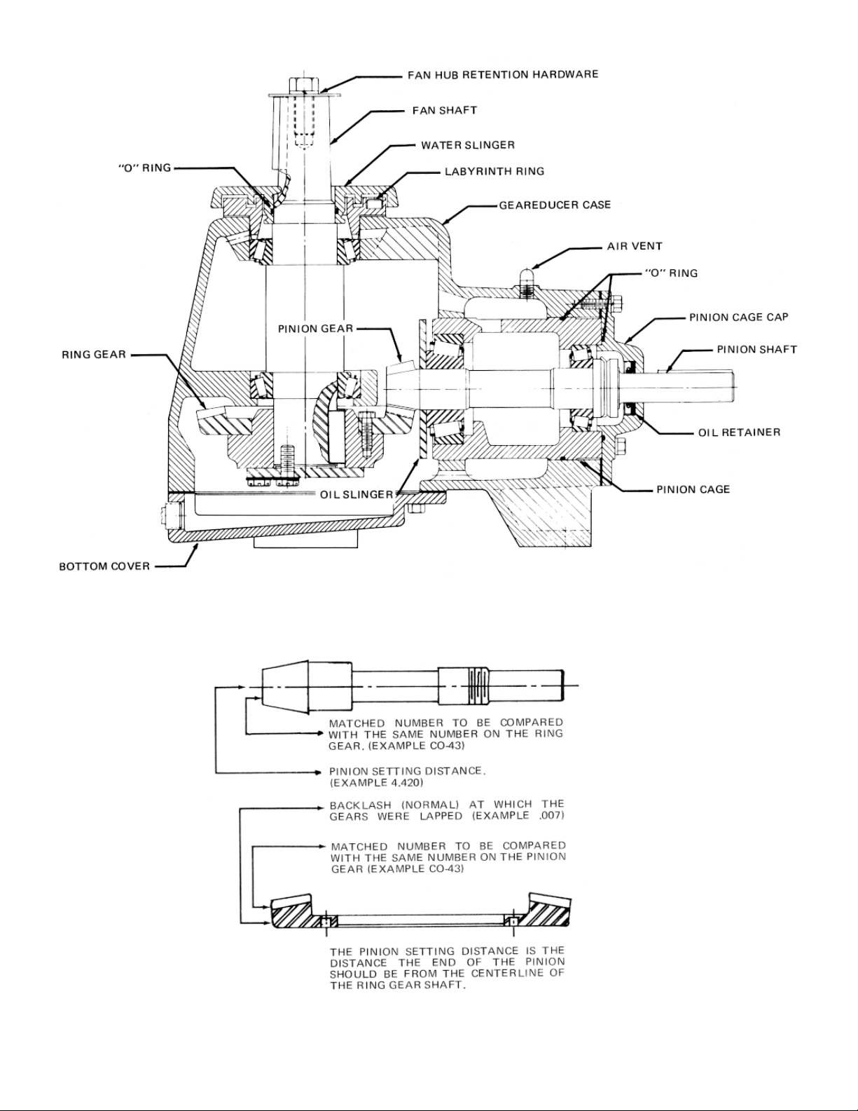
Series 20, 20T & 20.1 Cross Section
Figure 1. Gear Match Numbers and Setting Data
– 2 –
Page 3

Field Repair Instructions
FOR SERIES 20, 20T & 20.1 MARLEY GEAREDUCER
STANDARD AND TYPE CC (EXTENDED FAN SHAFT)
GENERAL
Geareducers can be repaired in the field; however, major
repairs require the use of a fully equipped machine shop.
When field repair or replacement of parts is necessary, the
following procedure is recommended for the disassembly and
assembly of the unit. If any “O” ring, oil retainer or gasket is to
be re-used, care should be taken not to damage it during
disassembly. Parts which contain “O” rings or seals should not
be jerked or twisted past a shoulder or edge. These parts are
marked with an asterisk (*) in the description below. All “O”
rings, oil retainers, and gaskets should be carefully inspected
for damage before being reinstalled. Marley recommends that
new “O” rings and oil retainer be installed during a major
overhaul. Gasket is replaced by Permatex No. 2. See Figure
5, page 7.
DISASSEMBLY
Item numbers refer to Fig. 2, pages 4 and 5.
1. Remove drain plug (Item 1) and drain oil.
2. Remove outer ring of bolts (Item 2.1) in pinion cage cap
(Item 2.2) and remove pinion sub-assembly* (Item 2).
CAUTION: The thickness of this shim pack (Item 2.3) is
important in the resetting of the gears. The shim pack
should either be saved or carefully measured with a
micrometer. If the gears are to be replaced, record the
pinion setting distance that is etched on the pinion gear.
3. Remove bottom cap (Item 3).
4. Remove fan shaft disc (Item 5) and shim pack (Item 5.1)
and pull ring gear hub (Item 6).
CAUTION: The thickness of this shim pack (Item 5.1) is
important in the backlash setting of the gears. The shim
pack should either be saved or carefully measured with a
micrometer.
fan shaft disc and place bolts, or a hub puller can be used
by making a special plate; similar to the fan shaft disc, with
a clearance hole that will allow the puller to push against
The gear hub may be removed by using the
the fan shaft (Item 10). Loosely attach plate to gear hub
and pull against plate with hub puller. A metal disc should
be placed between the fan shaft and the hub puller to
protect the end of the fan shaft.
5. Remove water slinger* (Item 7).
6. Remove labyrinth ring (Item 8) and shim (Item 9).
7. Press or pull fan shaft (Item 10). The top bearing cup (Item
11) will be removed with the fan shaft.
8. Remove ring gear (Item 12) from ring gear hub.
PINION CAGE DISSASSEMBLY
1. Remove pinion cage cap* (Item 2.2) from pinion cage
(Item 2.4).
2. Remove “O” rings (Items 2.5 and 2.6).
3. Remove locknuts (Item 2.7) and lockwasher (Item 2.8);
then press pinion shaft (Item 2.9) out of pinion cage. This
will free tail bearing cone (Item 2.10). A hydraulic press or
jack is recommended for removing or assembling press fit
parts.
4. Press oil slinger (Item 2.11) and head bearing cone (Item
2.12) from the pinion shaft. Bearings must not be exposed
to dirt, dust or moisture.
5. Press bearing caps (Item 2.13 and 2.14) out of pinion
cage.
6. If oil retainer (Item 2.15) in pinion cage cap is worn or
damaged and is to be replaced, it can be removed with a
hammer and punch.
FAN SHAFT ASSEMBLY
1. Press or pull top bearing cone (Item 13) from end of fan
shaft.
2. Press or pull bottom bearing cone (Item 14) from fan shaft.
3. Press bottom fan shaft bearing cup (Item 15) out of case.
– 3 –
Page 4

Figure 2. Exploded Cross-Section Series 20, 20T & 20.1 Geareducer
– 4 –
Page 5

Figure 3. Gear Backlash Measurement
– 5 –
Figure 4. Bottom Cap
Early models were supplied with a
gasket between the case and bottom
cap. In place of gasket, use Permatex
"Form-A-Gasket" No. 2 as shown.
Page 6

ASSEMBLY
Before assembling a new pinion gear in the pinion cage, check
match numbers on pinion gear and spiral bevel ring gear to be
certain that they are a matched set. Gears are lapped in
matched sets at the factory and should not be separated.
Numbers are etched on both the pinion and ring gear as
illustrated in Fig. 1, page 2.
All parts that are to be reused should be thoroughly cleaned
with Kerosene before being reinstalled. Do not remove new
bearings from carton until ready to use. Wash all bearings (new
or old) with Kerosene. Do not spin-dry bearings. Take each
bearing set and roll the cup on the cone to note any roughness.
Replace bearing if necessary. If bearings cannot be installed
immediately after washing, lubricate and cover them to protect
against dust, moisture, etc.
If a press is not available to install bearing cones, they can be
heated as long as the temperature does not exceed 275°300°F. If the bearings get hotter than this, they will begin to
draw and soften. Bearings can be heated with infrared lamps
or with oil baths. If an oil bath is used, the bearing should be
supported an inch or so above the pan to prevent local
overheating.
PINION CAGE SUB-ASSEMBLY
1. Place oil slinger (Item 2.11) on pinion shaft (Item 2.9).
2. Press head bearing cone (Item 2.12) on pinion shaft
making sure oil slinger and bearing are against gear.
3. Press bearing cups (Items 2.13 and 2.14) into pinion cage
(Item 2.4).
4. Lower pinion cage on pinion shaft, until head bearing cone
and cup mate.
5. Press tail bearing cone (Item 2.10) on pinion shaft until it
mates with its bearing cup.
6. Install locknuts (Item 2.7) and lockwasher (Item 2.8).
Tighten nuts on bearing cone until 5 to 15 inch pounds of
bearing preload is obtained. Bearing preload is the resistance in the bearings to shaft rotation measured in in./lbs.
torque required to rotate the shaft at uniform velocity.
Preload is necessary to insure the stability of the gear
engagement. Crimp the lockwasher to hold the two nuts
in place.
7. Install “O” ring (Item 2.6) in groove.
8. Install oil retainer (Item 2.15) in pinion cage cap (Item 2.2).
This seal is to prevent oil leaking out of the Geareducer;
therefore, the sealing lip must point inward. Clean oil
retainer seat in cap and press retainer in place. Use a
short piece of pipe with outside diameter .010 to .020 in.
Iess than the retainer outside diameter. Do not apply
hammer blows or uneven pressure directly to seal surface. Be careful not to tip retainer while installing it.
Provide a sleeve to protect the seal lip as it passes over
the shaft keyway. Shim stock .010 to .015 inch thick can
be used for this sleeve as long as the lapping edge is
smoothed off and the seal is turned with the lap in the
sleeve rather than against it. A small amount of light
grease can be used to lubricate the sealing lip.
9. Position “O” ring (Item 2.5) and push cap (Item 2.2) (with
seal and sleeve) in place on shaft. Attach cap to pinion
cage and slide sleeve from cap.
10. Record the pinion setting distance that is etched on the
pinion gear.
INSTALLATION OF FAN SHAFT
1. Press bottom bearing cup (Item 15) in case.
2. Press bearing cones (Item 13 and 14) on fan shaft (Item
10).
3. Lower fan shaft into case until bearing cone mates with
bearlng cup.
4. Press top bearing cup (Item 11 ) into case.
5. Install labyrinth ring (Item 8) and adjust cap screws (Item
16) until a bearing preload of 5 to 15 inch pounds is
obtained. Measure the gap between the labyrinth ring and
the case. Make a shim pack (Item 9) equal to the thickness
of this gap. Remove ring and install shim pack. Reinstall
labyrinth ring and check bearing preload. If necessary,
adjust shim gap to obtain the proper bearing preload .
INSTALLATION OF RING GEAR HUB
1. Attach ring gear (Item 12) to hub (Item 6). (Use 30 to 35
foot pounds torque on place bolts.)
2. Press ring gear hub on the fan shaft.
CAUTION: Block the end of the fan shaft while pressing
hub on shaft. Do not press against top bearing.
tapped hole (5/8-11NC x 1.00 deep) in the end of the fan
shaft may be used to pull the hub on. (If the tapped hole
is used, check around the hole after the hub is on to be
sure there are no raised edges that would keep the shims
(Item 5.1 ) from seating properly against the shaft.) Stop
the bottom edge of the hub approximately .100 from the
end of the shaft.
INSTALLATION OF PINION CAGE
1. The “X” marked pinion and gear teeth should be clearly
identified with chalk or other markings which can be seen
from the inspection opening or the bottom of the case.
2. Find the difference between the pinion setting distance of
the old gear and the new pinion gear and adjust the old
shim pack (Item 2.3) or make a new shim pack to compensate for the different setting distances.
The
– 6 –
Page 7

Correct Pinion & Gear Tooth Contact Patterns Incorrect Ring Gear Tooth Contact Pattern
Figure 5. Tooth Contact Pattern Correct and Incorrect
Example:
Pinion setting distance of old gear 2.883
Pinion settinq distance of new qear
2.878
Difference .005
Remove .005 from shim gap.
3. Install shims (Item 2.3) and pinion cage sub-assembly
(Item 2). CARE MUST BE TAKEN NOT TO DAMAGE the
pinion gear teeth by forcing them into the ring gear teeth.
GEAR SETTING PROCEDURE
The proper mounting of the gear set is essential to obtain long
life and smooth operation of the gears. The pinion and ring
gears were positioned approximately in the preceding steps.
The correct gear position is determined by the gear tooth
contact pattern and by the backlash.
With the “X” marked tooth on the pinion gear engaged between
the two “X” marked teeth on the ring gear, check the backlash
with a dial indicator as shown in Fig. 3. Lock the pinion shaft
against rotation. The amount of movement of the fan shaft,
measured at a distance equal to the outside radius of the ring
gear is the backlash. The backlash on all gear ratios should be
between .005 and .012. With the “X” teeth engaged the
backlash should be approximately in the middle of the allowable range. Adjust the ring gear axially until the proper backlash is obtained. Check the backlash at three other points
around the ring gear to be sure the backlash is within the
specified limits. The fan shaft disc and the standard place bolts
may be used to adjust the ring gear in either direction. After the
correct backlash is obtained, remove fan shaft disc and measure the distance from the end of the fan shaft with a depth
micrometer. Install a shim pack (Item 5.1) equal to this depth
and replace the disc. (Tighten the inside bolt circle before
tightening the outside bolt circle. Use 85 to 90 foot pounds
torque.)
With gears adjusted to the proper backlash, blue (Prussian
blue in oil) the pinion teeth. (By using a long handled brush or
swab, the pinion teeth can be reached through the inspection
opening.) Drive the pinion by turning the fan shaft in both
directions for several revolutions. Observe the markings on
both gears on both sides of the teeth. Compare the markings
with the contact pattern shown in Figure 5. If contact pattern is
incorrect, adjust the pinion position with shims between the
pinion cage cap and Geareducer case.
When tooth contact is correct, recheck backlash. If necessary,
adjust ring gear to obtain proper backlash and recheck contact
pattern. Proper contact is the more important of the two. On a
used set of gears, it may be necessary to set the gears with
slightly greater backlash in order to obtain proper tooth contact. Should a condition be encountered where correct contact
cannot be obtained, the Geareducer should be returned to
Marley’s Olathe, Kansas plant in exchange for a factory
reconditioned unit.
FINAL ASSEMBLY
1. Apply 1/8" diameter bead of Permatex No. 2 to flange of
bottom cap. Bead to be centered on flange, and to be
inside of and adjacent to bolt holes (see Figure 4).
2. Install bottom cap and tighten attaching cap screws to 25
ft./lbs. torque.
3. Install “O” ring (Item 17) in water slinger (Item 7).
4. Fill grooves of the labyrinth ring (Item 8) and water slinger
(Item 7) with a lithium base grease (NLGI-2).
5. Install water slinger on fan shaft (Item 10).
6. Replace air vent and all pipe plugs.
7. Fill with lubricant selected from Table 1, page 8. Refer to
Geareducer Service Manual for complete service and
lubrication instructions.
Recheck the backlash to make sure it is within the proper limits.
– 7 –
Page 8

LUBRICANTS FOR MARLEY GEAREDUCERS
To insure maximum performance and service life, The Marley
Cooling Tower Company recommends Marley factory approved oils be used in all Marley spiral bevel Geareducers. You
can purchase Marley approved oils through your local Marley
sales office in one-gallon and five-gallon containers.
If you must use any oil other than Marley factory approved oil,
the lubricant must not contain any additives (such as deter-
Turbine-type mineral oils conforming to the viscosity requirements outlined in Table I may be used. These lubricants will provide
service life of up to six months.
gents or EP additives) which are adversely affected by moisture and could reduce the service life of the Geareducer. The
responsibility for use of oils other than Marley approved
lubricants rests with the customer/user and the lubricant
supplier.
Seasonal temperature changes may require one viscosity of
oil for summer operation and another for winter operation. Use
the following table as a guide.
Table I. Air Temperature at Geareducer
Winter
Below 32°F
SAE 20
Viscosity S.U.S.
At 100°F 230-310
(Heat Exchangers Only)
The Mobil synthetic lubricants listed below may be used where extended service intervals are desired (up to five years).
Winter or Summer
32°F to 110°F
SAE 30
Viscosity S.U.S.
At 100°F 450-610
Summer
Above 110°F
SAE 40
Viscosity S.U.S.
At 100°F 750-1000
Table II. Air Temperature at Geareducer
Winter or Summer
32°F to 110°F
Mobil SHC 629
Severe Duty/High Temperature
Above 110°F
Mobil SHC 630
5800 Foxridge Drive — P.O. Box 2912 — Mission, Kansas 66202
913 362-1818
– 8 –
 Loading...