

Page 1
NOTE: Accessories described in this instruction manual are
intended for use with Marley Engineered Products G Series Fan
Forced Wall Heaters only.
INSTALLATION
NOTE: It is recommended that no more than one thermostat be
used in each room (or area).
1. The thermostat must be installed in right end of the heater.
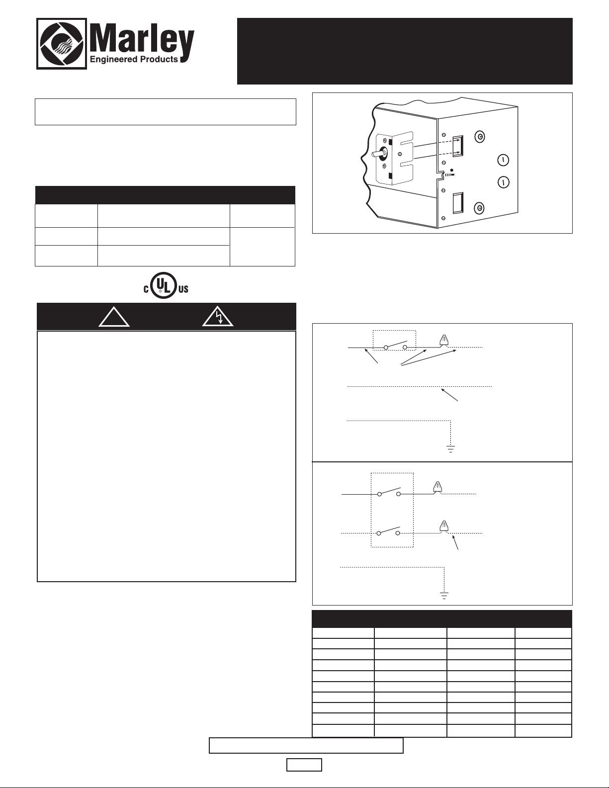
2. Position thermostat above slot in right end of back box.
Push tab on thermostat bracket through slot in top, right end
of back box until the bracket locks in place. See Fig. 1.
3. If the thermostat is controlling more than one heater, the total
of all heater amperage ratings (Table 1) cannot exceed 22
amps at 120 volts AC thru 240 volts AC. Refer to Table 2 for
correct wire, circuit breaker, or fuse sizing.
4. Connect thermostat to heater and power wiring per wiring
diagram (Fig. 2a & 2b) using properly sized listed wire nuts.
5. Fold wires back into wiring compartment. Remove 1/2”
knockout from grille and install grille. Push thermostat knob
on thermostat shaft.
6. Reconnect power at main fuse or circuit breaker distribution
panel.
G Series Thermostat Accessories
Single & Double Pole
Installation Instructions
Model No.
GTSP
GTDP
Electrical
Ratings
22 A
120/240 AC
Description
Single Pole
Double Pole
SPECIFICATIONS
WARNING
!
This instruction sheet contains vital information for the proper
installation and use of the accessories described herein.
Carefully read this manual before installation, operation, or service of the accessory. Failure to follow these instructions could
result in fire, electric shock, death, serious personal injury, or
property damage. Save these instructions for reference by future
users.
WARNING: HAZARD OF FIRE OR ELECTRIC SHOCK.
1. Be sure electric power is disconnected at main fuse or circuit
breaker distribution panel before installation or servicing.
2. The installation must comply with all Local and National
Electrical Codes and utility requirements.
3. Refer to installation instructions provided with the heater
when installing these accessories.
4. Check accessory and heater nameplate to verify power
requirements match power supply coming to heater and
accessory. Make sure total power requirements do not
exceed ratings of accessory..
1
SAVE THESE INSTRUCTIONS
1-pole stat
Black
To Heater
L2 or N
To Heater
White-120V
Black-208V
Red-240V
GND-Green
2-pole stat
To Heater
L2 or N
To Heater
White-120V
Black-208V
Red-240V
GND-Green
Red
L1
Off
L2
Cycle
Red
Black
Black Black
L1
L1
Figure 2a
Figure 2b
Figure 1
TABLE 1
MODEL
G0512IF
G1012IF
G1512IF
G2028IF
G0524IF
G1024IF
G1524IF
G2024IF
G2224IF
VOLTS
120
120
120
208
240
240/208
240/208
240/208
240/208
WATTS
500
1000
1500
2000
500
1000/750
1500/1125
2000/1500
2250/1688
AMPS
4.2
8.3
12.5
9.6
2.1
4.2/3.6
6.3/5.4
8.3/7.2
9.4/8.1
Page 2
OPERATION CHECK
1. After your G Series wall heater has been completely
installed, all thermostats, whether single pole or double pole,
should be turned to LOW or OFF. Turn on breakers or
install fuses. Wait 3 to 5 minutes and check to make sure the
heater is not operating. Should it be operating, disconnect
power and check your wiring. If not operating, turn the
thermostat to the highest position and wait another 3 to 5
minutes. Then check to see that all heaters are operating.
Should it not be operating, again disconnect power and
check your wiring.
2. Allow heater to operate steadily for 1/2 hour.
3. Select the setting for your comfort level.
NOTE: Your electric heating system has many advantages,
one of which is zone or room-by-room control. If you desire to
keep a seldom used room at a lower temperature, this may be
done by lowering the thermostat setting and closing the door.
However, DO NOT try to control different rooms at different temperatures unless the doors are kept closed. This will tend to
increase operating cost and decrease comfort. It is advisable,
if rooms are kept open, that all thermostats have the same setting. By following these instructions you will enjoy greater comfort.
LIMITED WARRANTY
All products covered by this instruction sheet are warranted against defects in workmanship and materials for one year from date of installation. This warranty does not apply
to damage from accident, misuse, or alteration; nor where the connected voltage is more than 5% above the nameplate voltage; nor to equipment improperly installed or wired
or maintained in violation of this instruction sheet. All claims for warranty work must be accompanied by proof of the date of installation.
The customer shall be responsible for all costs incurred in the removal or reinstallation of products, including labor costs, and shipping costs incurred to return products to a
Marley Engineered Products Service Center, and we will repair or replace, at our option, at no charge to you with return freight paid by Marley. It is agreed that such repair
or replacement is the exclusive remedy available from Marley Engineered Products.
THE ABOVE WARRANTIES ARE IN LIEU OF ALL OTHER WARRANTIES EXPRESSED OR IMPLIED, AND ALL IMPLIED WARRANTIES OF MERCHANTABILITY AND
FITNESS FOR A PARTICULAR PURPOSE WHICH EXCEED THE AFORESAID EXPRESSED WARRANTIES ARE HEREBY DISCLAIMED AND EXCLUDED FROM THIS
AGREEMENT. MARLEY ENGINEERED PRODUCTS SHALL NOT BE LIABLE FOR CONSEQUENTIAL DAMAGES ARISING WITH RESPECT TO THE PRODUCT,
WHETHER BASED UPON NEGLIGENCE, TORT, STRICT LIABILITY, OR CONTRACT.
Some states do not allow the exclusion on limitation of incidental or consequential damages, so the above exclusion or limitation may not apply to you. This warranty gives
you specific legal rights, and you may also have other rights which vary from state.
For the address of your nearest authorized service center, contact Marley Engineered Products, 470 Beauty Spot Road East, Bennettsville, SC 29512 USA. Merchandise
returned to the factory must be accompanied by a return authorization and service identification tag, both available from the above location. When requesting return authorization, include all catalog numbers shown on the products.
5200-2426-001
10/08
ECR 37958
2
FIELD WIRE & PROTECTION CHART
TABLE 2
TOTAL AMPS
0 thru 12
12.1 thru 16
16.1 thru 24
WIRE SIZE
(COPPER)
#14
#12
#10
CIRCUIT BREAKER
OR FUSE SIZE
15 Amps
20 Amps
30 Amps
IMPORTANT INFORMATION
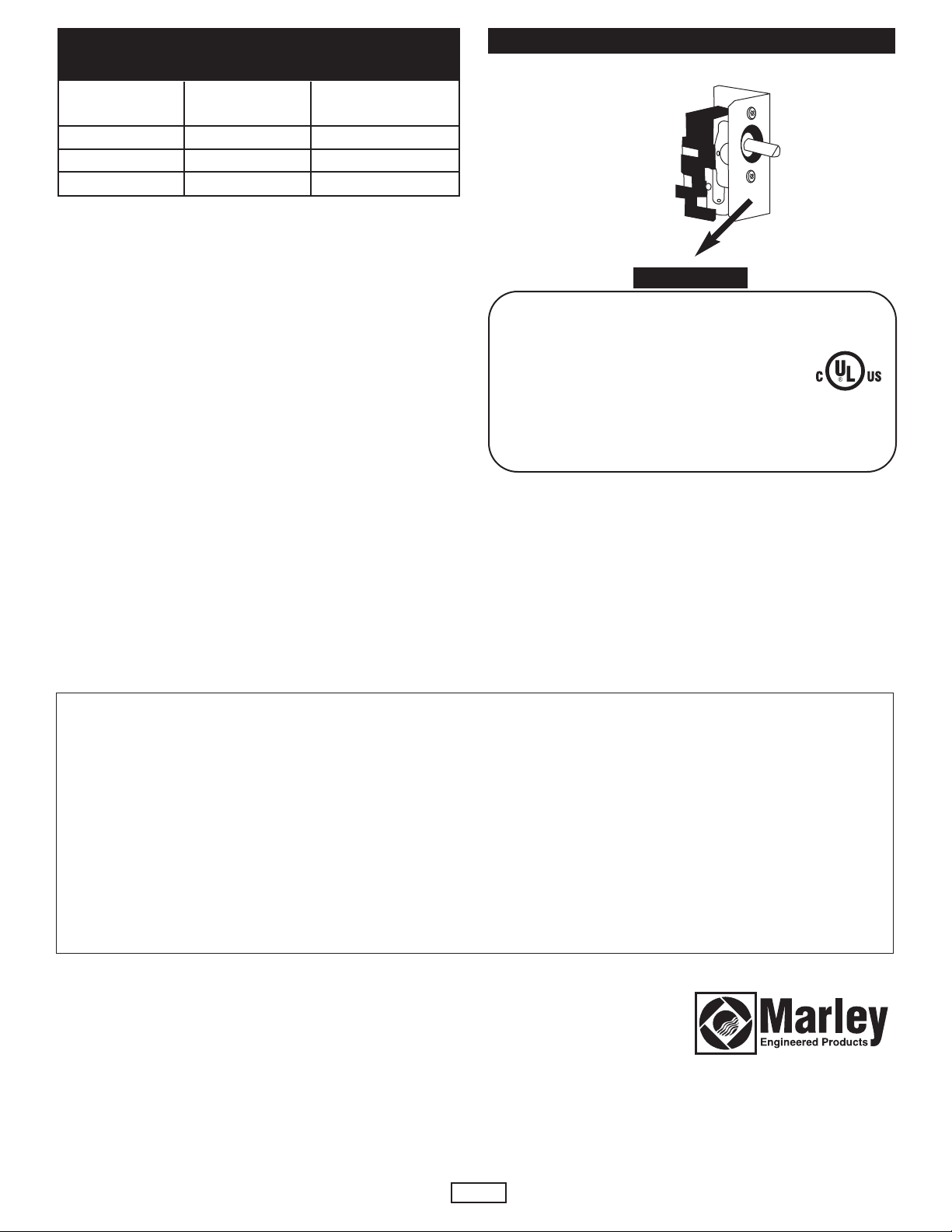
NAMEPLATE
DATE CODE
0399 GTSP
Marley Engineered Products1 POLE STAT
BENNETTSVILLE, SC 29512 774G LISTED
ROOM HEATER
ACCESSORY
4104-2160-004 VAC 60 HZ AMPS
120 - 240 22 RES.
470 Beauty Spot Rd. East
Bennettsville, SC 29512 USA
HOW TO OBTAIN WARRANTY SERVICE AND
WARRANTY PARTS PLUS GENERAL INFORMATION
1. Warranty Service or Parts 1-800-642-4328
2. Purchase Replacement Parts 1-800-654-3545
3. General Product Information www.marleymep.com
Note: When obtaining service always have the following:
1. Model number of the product
2. Date of manufacture
3. Part number or description
 Loading...