

Page 1
Type CSL
Commercial Sill Height
Commercial
Sill Height Convection Heaters
(Type CSL)
Convectors
Installation, Operation & Maintenance Instructions
IMPORTANT INSTRUCTIONS
General
This heater is designed to provide years of efficient, trouble free operation as a primary or supplemental heat source for comfort
heating in residential (Model CSLAS, 250 watt max only) and commercial applications. Installation or use of this product in any
manner not described within this manual will void the warranty and could result in injury, damage to property, or permanent damage
to heater.
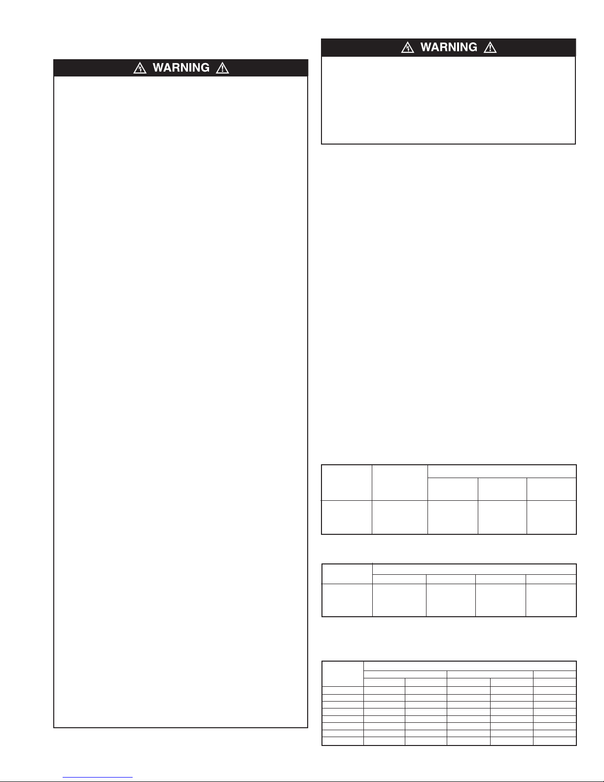
WARNING
WHEN USING ELECTRICAL APPLIANCES, BASIC PRECAUTIONS SHOULD ALWAYS BE FOLLOWED TO REDUCE
THE RISK OF FIRE, ELECTRIC SHOCK, AND INJURY TO
PERSONS, INCLUDING THE FOLLOWING:
1. Read all instructions before installing or using the heater.
2. A heater has hot and arcing or sparking parts inside. Do not
use in areas where gasoline or flammable liquids are used
or stored. Do not use in corrosive environment or any area
where explosive materials are used or stored.
3. This heater is hot when in use. To avoid burns, do not let
bare skin touch hot surfaces. Keep combustible materials,
such as furniture, pillows, bedding, papers, clothes, and cur-
RECEIVING
Material when shipped was in good order and Marley
Engineered Products holds clear bill of lading, therefore any
concealed damage must be reported at once to the carrier for
inspection and settlement.
SAVE THESE INSTRUCTIONS
!
tains away from heater.
4. To prevent a possible fire, do not block air intakes or
exhaust in any manner.
5. Do not insert or allow foreign objects to enter any ventilation
or exhaust opening as this may cause an electric shock, fire,
or damage the heater.
6. Serious injury or death could result from electric shock.
Make sure electrical power supply circuit coming to heater
is disconnected at main disconnect or service panel before
installing or servicing this heater.
7. This heater is not for residential or household use, except
model CSLAS @ 250 watts per foot.
Note:
It is advisable to store cartons in a central area to be
drawn upon as needed per room requirements. If called for on
order, the cartons will have been tagged with proper room
number.
Page 2
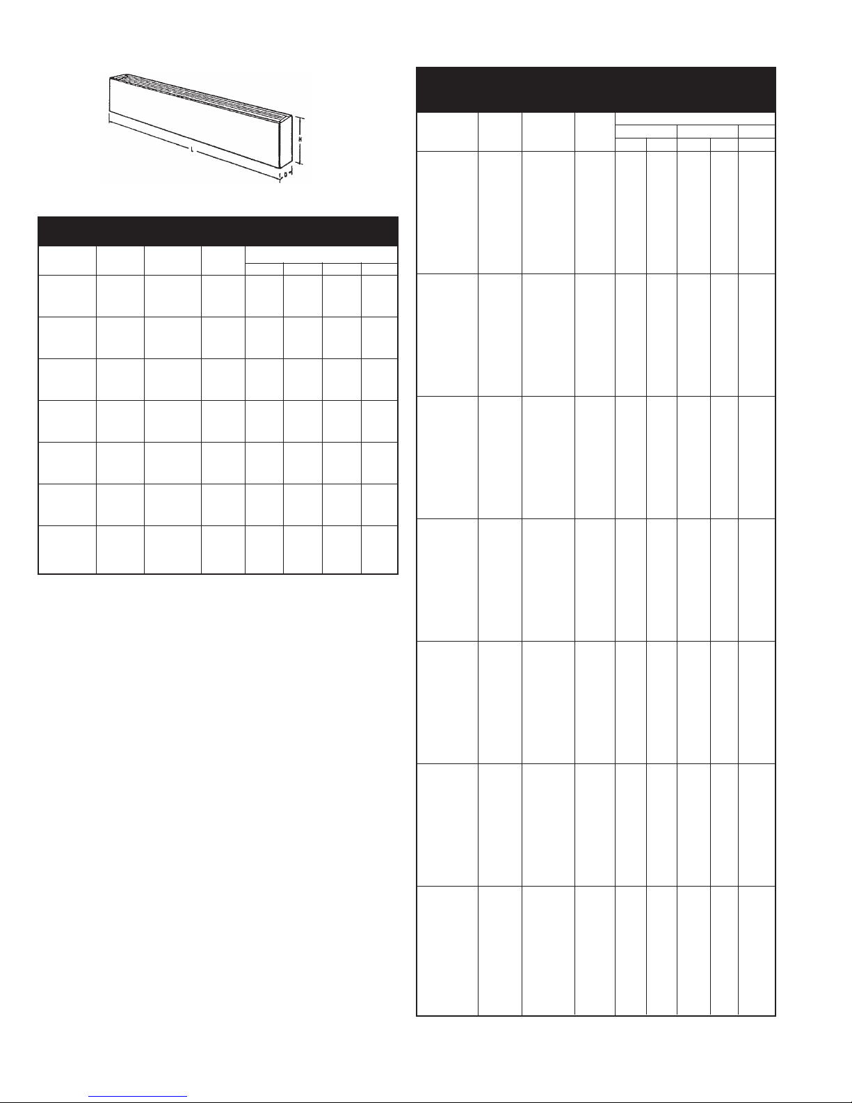
SPECIFICATIONS
Type CSL
Figure 1
Table A
Model CSLAS (H=5 1/2”; D=3”)
Catalog Length Total Amperage
Number* “L” Watts/Ft. Watts 120V 208V 240V 277V
-2125 125 250 2.4 1.2 1.0 0.9
-2188 28” 188 375 3.1 1.8 1.6 1.4
-2250 250 500 4.2 2.4 2.1 1.8
-3125 125 375 3.1 1.8 1.6 1.4
-3188 3’ 188 564 4.7 2.7 2.4 2.0
-3250 250 750 6.2 3.6 3.1 2.7
-4125 125 500 4.2 2.4 2.1 1.8
-4188 4 188 750 6.2 3.6 3.1 2.7
-4250 250 1000 8.3 4.8 4.2 3.6
-5125 125 625 5.2 3.0 2.6 2.2
-5188 5 188 940 7.8 4.5 3.9 3.4
-5250 250 1250 10.4 6.0 5.2 4.5
-6125 125 750 6.2 3.6 3.1 2.7
-6188 6 188 1125 9.4 5.4 4.7 4.1
-6250 250 1500 12.5 7.2 6.2 5.4
-8125 125 1000 - 4.8 4.2 3.6
-8188 8’ 188 1500 - 7.2 6.2 5.4
-8250 250 2000 - 9.6 8.3 7.2
-10125 125 1250 - 6.0 5.2 4.5
-10188 10’ 188 1875 - 9.0 7.8 6.7
-10250 250 2500 - 12.0 10.4 9.0
Clearance Chart
For safe and efficient operation, maintain at least the following
Minimum clearances at all times:
Bottom of heater to finished floor
Watts/Ft Heater Length Bottom Inlet Front Inlet
125, 188 and 250 1-3/4” (44 mm) 0” (0 mm)
376 500, 625, and 750 3” (76 mm) 0” (0 mm)
Top of heater to bottom of Drapes above heater:
Minimum 12 inches (305 mm)
Important Note:
vinyl blinds) may become damaged by the heated air from the
heater and should not be installed above the heater.
Front of heater to full length drapes in front of heater:
Minimum between bottom of drapes and floor - 2 1/2 inches
(64 mm)
Minimum between top of drapes and ceiling - 1/2 inches
(13 mm)
Minimum between front of heater and nearest fold of drape 2 inches
Top of heater to bottom of window sill:
Minimum 12 inches (305 mm)
Certain fabrics and vinyl materials ( such as
Table A (continued)
Model CSLAM (H=7”; D=5”)
Model CSLAL (H=14”; D=5”)
Amperage
Catalog Length Total 208V 240V 277V
Number** “L” Watts/Ft Watts 1Ø 3Ø 1Ø 3Ø 1Ø
-2125 125 250 1.2 - 1.0 - 0.9
-2188 188 375 1.8 - 1.6 - 1.4
-2250 250 500 2.4 - 2.1 - 1.8
-2375 28” 375 750 3.6 - 3.1 - 2.7
-2500 500 1000 4.8 - 4.2 - 3.6
-2564 564 1125 5.4 3.1 4.7 2.7 4.0
-2625 625 1250 6.0 3.5 5.2 3.0 4.5
-2750 750 1500 7.2 4.2 6.2 3.6 5.4
-3125 125 375 1.8 - 1.6 - 1.4
-3188 188 564 2.7 - 2.4 - 2.0
-3250 250 750 3.6 - 3.1 - 2.7
-3375 3’ 375 1125 5.4 - 4.7 - 4.0
-3500 500 1500 7.2 - 6.2 - 5.4
-3564 564 1690 8.1 4.7 7.4 4.3 6.1
-3625 625 1875 9.0 5.2 7.8 4.5 6.7
-3750 750 2250 11.0 6.5 9.4 5.4 8.1
-4125 125 500 2.4 - 2.1 - 1.8
-4188 188 750 3.6 - 3.1 - 2.7
-4250 250 1000 4.8 - 4.2 - 3.6
-4375 4’ 375 1500 7.2 - 6.2 - 5.4
-4500 500 2000 9.6 - 8.3 - 7.2
-4564 564 2250 10.8 6.2 9.4 5.4 8.0
-4625 625 2500 12.0 6.9 10.4 6.0 9.0
-4750 750 3000 14.4 8.3 12.5 7.2 10.8
-5125 125 625 3.0 - 2.6 - 2.2
-5188 188 940 4.5 - 3.9 - 3.4
-5250 250 1250 6.0 - 5.2 - 4.5
-5375 5’ 375 1875 9.0 - 7.8 - 6.7
-5500 500 2500 12.0 - 10.4 - 9.0
-5564 564 2820 13.5 7.8 11.8 6.8 10.2
-5625 625 3125 15.0 8.7 13.0 7.5 11.3
-5750 750 3750 18.0 10.4 15.6 9.0 13.5
-6125 125 750 3.6 - 3.1 - 2.7
-6188 188 1125 5.4 - 4.7 - 4.0
-6250 250 1500 7.2 - 6.2 - 5.4
-6375 6’ 375 2250 10.8 - 9.4 - 8.1
-6500 500 3000 14.4 - 12.5 - 10.8
-6564 564 3380 16.2 9.4 14.1 8.1 12.2
-6625 625 3750 18.0 10.4 15.6 9.0 13.5
-6750 750 4500 21.6 12.5 18.7 10.8 16.2
-8125 125 1000 4.8 - 4.2 - 3.6
-8188 188 1500 7.2 - 6.2 - 5.4
-8250 250 2000 9.6 - 8.3 - 7.2
-8375 8’ 375 3000 14.4 - 12.5 - 10.8
-8500 500 4000 19.2 - 16.7 - 14.4
-8564 564 4500 21.6 12.5 18.7 10.8 16.2
-8625 625 5000 24.0 13.9 20.8 12.0 18.0
-8750 750 6000 28.6 16.5 15.0 14.4 21.6
-10125 125 1250 6.0 - 5.2 - 4.5
-10188 188 1875 9.0 - 7.8 - 6.7
-10250 250 2500 12.0 - 10.4 - 9.0
-10375 10’ 375 3750 18.0 - 15.6 - 13.5
-10500 500 5000 24.0 - 20.8 - 18.0
-10564 564 5640 27.2 15.7 23.5 13.6 20.4
-10625 625 6250 30.0 17.3 26.0 15.0 22.6
-10750 750 7500 36.0 20.8 31.3 18.1 27.0
2
Page 3
INSTALLATION INSTRUCTIONS
TO REDUCE THE RISK OF FIRE AND ELECTRIC SHOCK
OR INJURY TO PERSONS, OBSERVE THE FOLLOWING:
1. Before installing this heater, remove and discard shipping
pads located within heater. Check to make sure heater is
not damaged.
2. Serious injury or death could result from electric shock.
Make sure electrical power supply circuit coming to heater
is disconnected at main disconnect or service panel
before installing this heater.
3. Wiring procedures and connections must be in accordance with the National Electrical Code (NEC) and local
codes. Refer to Wiring Diagram on heater and Figure 9.
Make sure all electrical connections are tight to prevent
possible overheating. Use Copper Supply Wire Only.
4. Verify the electrical power supply voltage matches the
voltage rating as printed on the heater nameplate.
CAUTION
the nameplate voltage as this will damage the heater and
could cause a fire.
5. Do not install the heater against combustible low-density
6. Do not install heater below an electrical convenience
CAUTION
trical cords (including telephone and computer cables),
drapes, and other furnishings away from heater. For efficient
and safe operation, we recommend maintaining a minimum of
6 inches (152 mm) clearance above and in front of the heater
at all times.
7. To reduce the risk of fire, do not store or use gasoline or
8. Do not install heater upside down or in any position other
9. Do not recess heater in wall or install heater inside any
10. When mounting heater, use care to secure heater to
11. Do not remove or bypass the safety limit control (thermal
12. The factory installed wires inside wireway are used to
13. Heaters that are not installed end to end must have end
- Never connect a heater to a voltage greater than
cellulose fiberboard surfaces, against or below vinyl wall
coverings, or below any materials that may be damaged
by heat such as vinyl or plastic blinds, curtains, etc. If
heater is intended to be installed against vinyl wall coverings, Stand Off Kits, Cat. No. SO1 or SO2, must be used.
See instructions supplied with kits.
receptacle (outlet).
– Heater operates at high temperatures. Keep elec-
other flammable vapors or liquids in the vicinity of the
heater.
than as shown in this manual. Caution label with word
“TOP” must be at the top when heater is installed.
type enclosure as this will cause heater to overheat and
could create a hazard.
building structure and avoid damaging internal heater
components.
protector) as this could allow heater to become a fire hazard – see heater wiring diagram supplied with heater.
connect the built-in controls. Limit the maximum current
to no more than 45 total amps. Refer to instructions and
current capacity rating as provided with the accessory.
caps installed to cover exposed ends of heater.
14. All field wiring brought in to heater must be rated minimum 75°C.
15 Do not allow objects to be placed on top of heater as they
may be damaged or create a fire hazard.
16. Before energizing, make sure that heater is completely
assembled with grille, front cover, end caps and any
accessories installed.
Rough-in Wiring
1. Run branch circuit of proper voltage and wire size to location
of left or right junction box as indicated on heater wiring diagram. Basic heaters are prewired and can be connected to
branch circuit at either end. Heaters with controls are
prewired for connection to branch circuit at one end only
(refer to heater wiring diagram), however, heater can be
wired from opposite end by running wire through heater wireway.
2. If it is necessary to run wires through the heater wireway,
use Table B to size the field installed wiring.
3. The factory installed wires in the heater wireway can be
loaded up to 45 amps. Refer to Table C for maximum length
of heater run when the heaters are connected in parallel.
Thermostat
Transformer relay
05A units: 22 amps @ 120-240 VAC
07A-14A Units: 25 AMPS @ 120-240 VAC
Power relay
Disconnect switch
Table B. Sizing Field Installed Wiring
Copper Maximum no.
wire size of wires Up to 3 4 to 6 7 thru 9
75º C in wireway Conductors Conductors Conductors
No. 12 AWG 9 11.5 amps 9.3 amps 8.1 amps
No. 10 AWG 8 17.4 amps 14.0 amps 12.1 amps
No. 8 AWG 4 24.0 amps 21.0 amps –
Table C. Maximum Length of Heater Run
(CSLAS-1Ø)
Watts/Ft. of Maximum allowable length of heater run (feet)
the heaters 120 Volts 208 Volts 240 Volts 277 Volts
125 33 58 67 77
188 22 38 44 51
250 16 29 33 38
Note:
For mix of watt densities, calculate amp draw. Do not
exceed values indicated in step 3 above.
Table D. Maximum Length of Heater Run
(CSLAM and CSLAL)
Watts/Ft.
of Heaters
125 74 - 86 - 99
188 49 - 57 - 66
250 37 - 43 - 49
376 24 - 28 - 33
500 18 - 21 - 24
564 16 27 19 32 22
625 15 24 17 29 20
750 12 20 14 24 16
1 Ph 3 Ph 1 Ph 3 Ph 1 Ph
3
24 amps @ 120-240 VAC
22 amps @ 277 VAC
Pilot duty– 125 VAC (all voltages)
19 amps @ 277 VAC
22 AMPS @ 277 VAC
25 amps @ 120-277 VAC- see wiring diagram on heater
20 amps @ 120-277 VAC
Maximum allowable current
Max. allowable length of heater run in feet (meters)
208V 240V 277V
Page 4
4. Standard 75ºC wiring must be used in junction boxes, wire-
HEATER
HEATERS
BUTTED
TOGETHER
HEATER
FILLER
SECTION
HEATER
INSIDE
CORNER
HEATER
OUTSIDE
CORNER
HEATER
END
CAP
TYPICAL INSTALLATION
SPLICE PLATE
KIT
SPLICE PLATE
KIT
ways, blank sections, filler sections, and corner sections.
Room Layout
Refer to heating plans for exact room arrangements of heaters
(with or without thermostat and/or relays and/or switches and
accessories.)
Check the heater section dimensions and the additional wall
length required for telescoping accessories (Figure 2) before
starting wall-to-wall type installation. Be certain all heaters and
accessories needed are at hand and are of correct finish.
10
N
N
N
N
/4”
3
2-15/16”
-1/4”
1
1-7/16”
ACK PANEL
B
1-1/8” & 7/8” DIA.
CONCENTRIC K.O.’s
1-7/16”
/8” & 1-1/8” DIA.
7
CONCENTRIC K.O.’s
ACK PANEL
B
B
A
1-15/16”
-1/4”
1
2-1/2”
3/4”
1-3/8” & 1-3/4” DIA.
ONCENTRIC K.O.’s
C
1-9/16”
10
7
3
Figure 2
Typical Installation
See page 8 for N dimensions
2
4
1
8
N
5
6
N
9
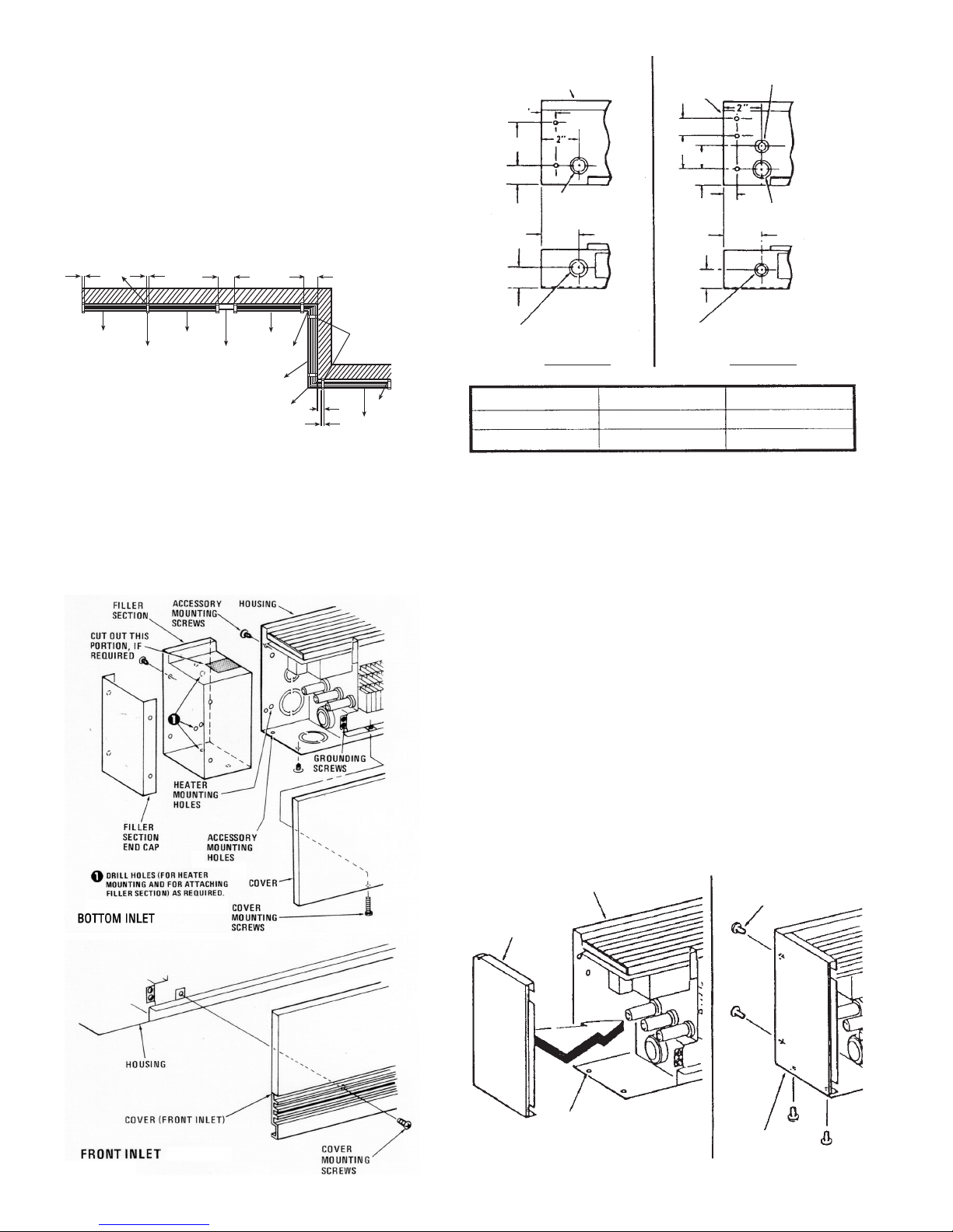
Installation of Single Unit
Note:
For ease of installation, it is important that the sequence
of operations indicated below be followed in order.
1. Remove front cover by removing mounting screws (Figure
3).
2. Remove appropriate electrical knockout from either junction
box. See Figure 4 for location of knockouts.
1-3/8” & 1-1/8” DIA.
ONCENTRIC K.O.’s
C
BOTTOM VIEW
1-3/8” & 1-3/4” DIA.
ONCENTRIC K.O.’s
C
BOTTOM VIEW
CSLAM CSLAL
A
B
4”
N/A
5”
5”
Figure 4
3. Install end caps (must be purchased separately) on both
ends of the heater housing. Refer to Figure 5 for details of
end cap installation.
4. If filler section is desired to terminate the heater, install the
filler section in the end of the heater and extend to desired
length. Mark the mounting hole locations, remove the filler
section and drill the required mounting holes. Install the filler
section in the heater and the end cap on the filler section as
shown in Figure 3.
Note:
If a thermostat and/or disconnect switch are installed in
the heater left junction box, it may be necessary to cut away a
portion of the filler section to allow access to these controls
(Figure 3).
5 Position heater housing on wall to check for evenness of
wall. Do not draw the heater against an uneven wall surface.
If an uneven wall is encountered, use shims to keep the
heater housing straight.
6. Run proper size branch circuit to the junction box through the
selected knockout.
Figure 3
HOUSING
MOUNTING
SCREWS
END
CAP
ACCESSORY
MOUNTING
END CAP
HOLES
Figure 5
4
Page 5
7. Drill the required size mounting holes in the back of the
heater housing and install the housing on the wall using
screws, bolts or anchors (by installer) to suit the wall construction.
Note:
Predrilled 1/4” diameter mounting holes are provided in
each junction box. Additional mounting holes will have to be
drilled in the housing to support the weight of long length
heaters (6’ and longer). Do not drill any additional holes in the
junction boxes.
8. Tighten mounting screws and back off 1/4 to 3/4 turn to
allow for expansion and contraction of the heater.
9. Following the wiring diagram secured to the heater, make
electrical connections. Ground the heater using the ground
screws provided (Figure 3).
10. Replace front cover and secure with mounting screws. (See
Figure 3).
Installation of Multiple Wall to Wall Units
Note:
For ease of installation, it is important that the sequence
of operations indicated below be followed in order.
1. Remove all the front covers from the heaters by removing
mounting screws (Figure 3).
2. Refer to wiring diagram for power supply entry and remove
appropriate electrical knockout (Figure 4) from the heater in
which power supply connections are to be made. The power
supply may be brought in to the end of only one heater and
the remaining heaters may be connected in parallel using the
wireway. Use Table B to size the field installed wiring in the
wireway.
3. If conduit cover (must be purchased separately) is desired,
cut off the appropriate length and install to the wall.
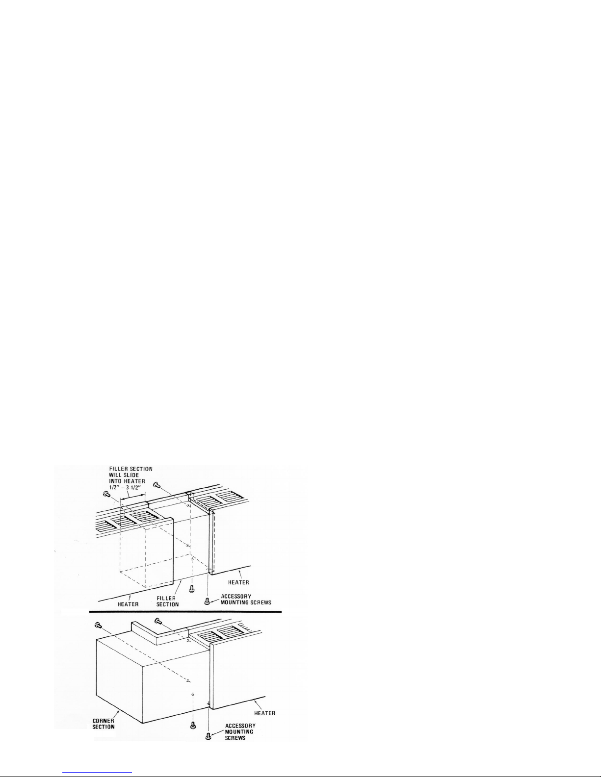
4. If required by plan, install filler section (1), (Figure 1) to either
heater (2) or (3) by means of four #6 screws supplied with
filler section. (Refer to Figure 6.) Discard filler section end
cap in this application.
Note:
Heaters may butt against each other, thus eliminating the
filler piece, if so desired.
Note:
If a heater has a disconnect switch and / or thermostat
and is to have a filler section or a corner section at the left end,
the section must be mounted to the heater since the thermostat
or disconnect switch will prevent the section from telescoping
into the heater.
5 If the wall run has inside or outside corners, install corner (4
and 5) to the heater (2 and 9) by means of four #6 screws
supplied with corner section. (Refer to Figure 6).
6. Install end caps (6) on the outer end of the last heater(7) and
(9) using four #6 screws supplied with end caps. (Refer to
Figure 5 for details of end cap installation.)
7. Drill the required size mounting holes in all the heater housings.
Note:
Predrilled 1/4” diameter mounting holes are provided in
each junction box. These holes may be used only when no slipin accessory is to be installed in that end of the heater ( such as
when heater(3 and 7) are butted together as shown in Figure 2).
Additional mounting holes will have to be drilled in the housing
to support the weight of long-length heaters (6’ and longer). Do
not drill any additional holes in junction boxes.
8. Check for evenness of wall. Do not draw the heaters
against an uneven wall surface. If an uneven wall is
encountered, use shims to keep the heater housing
straight.
9. Run proper size branch circuit to the junction box through
the selected knockout.
10. Mount the heater (2, Figure 2) on the wall using screws,
bolts or anchors (by installer) to suit the wall construction.
11. Telescope the heater housing (3) over the filler section (1)
by the desire amount and mount the housing to the wall.
12. Telescope the heater housing (8) over the corner section
(4) by the desired amount and mount the housing to the
wall.
13. Mount the remaining heaters as described above, making
sure that the heaters with end caps are installed at the end
of the run.
14. Blank sections, if any are installed in the same manner as
the heaters.
Note:
75ºC field wiring may be run through the blank sections,
filler sections and corner sections.
15. Control sections, if any, are installed in the same manner
as heaters. Refer to wiring diagram on control sections for
connecting the wiring to the heaters
Figure 6
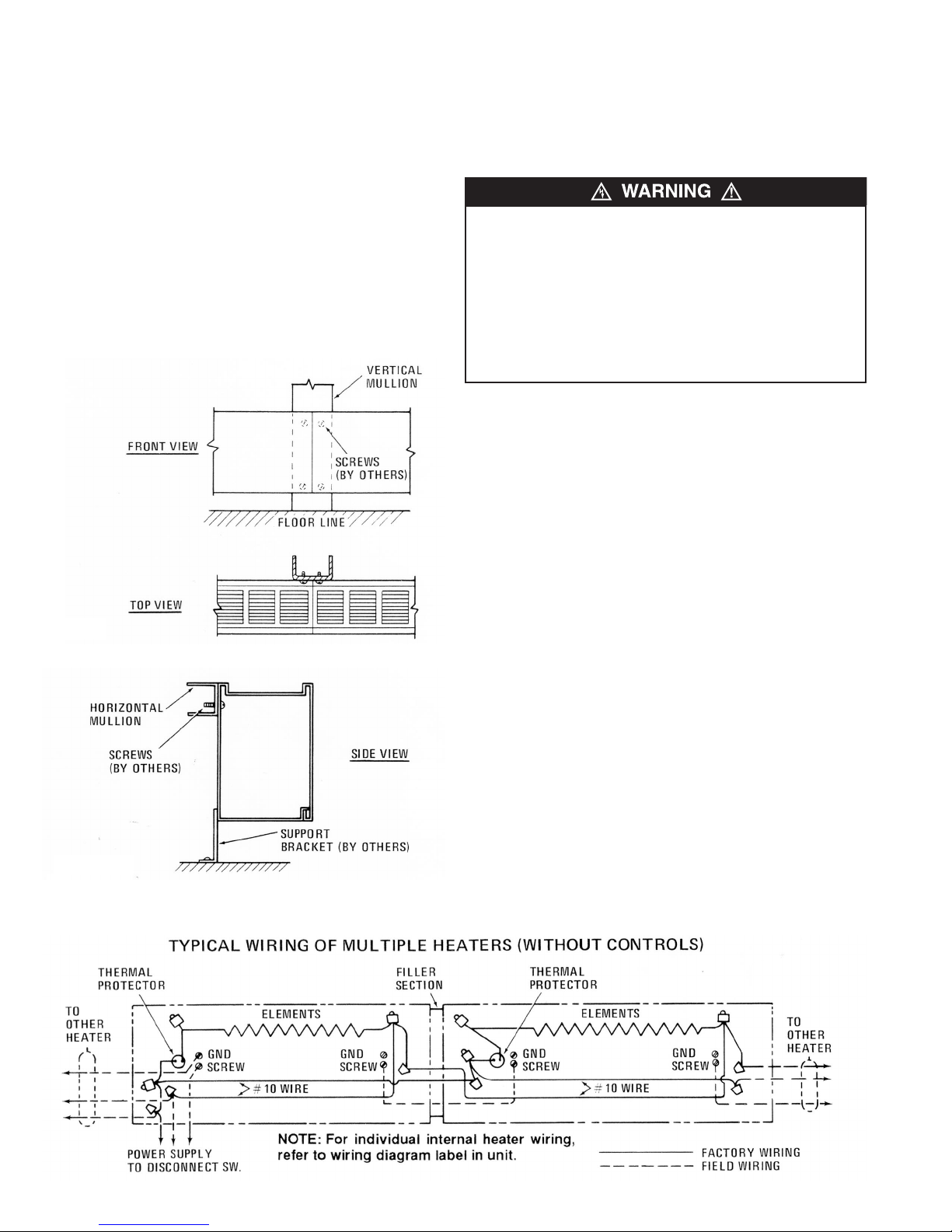
Installation of Mullion to Mullion Units
The back of the heater housing contains no mounting holes
(other than those at the ends) and therefore is ideal for installation in front of glass curtain walls. The housing back presents
an attractive appearance when viewed from the outside through
the glass wall.
Installation procedures are similar to those for wall-to-wall installation (Step Six) except for the following differences.
1. Attach the housing to the mullion using the mounting holes
provided in the junction boxes as shown in Figure 7.
2. On horizontal mullion installation, install support brackets as
shown in Figure 8.
5
Page 6
OPERATION INSTRUCTIONS
1. This heater must be properly installed before it is used.
2. If the heater is equipped with a built-in thermostat, adjust the
shaft to the mid-range and let the heater run for a few hours.
If the room temperature is too hot, rotate the shaft counterclockwise; if too cool, rotate the shaft clockwise until a comfortable temperature is obtained. Let room temperature stabilize after each setting change. The heater will automatically cycle around this set point on the thermostat.
Note:
If a thermostat or disconnect switch is provided in the
heater, these components are accessible through the grille
openings at the left or right end of the heater.
Figure 7
MAINTENANCE INSTRUCTIONS
For efficient and safe operation and to extend the life of the
heaters, they should be cleaned and inspected for damage at
least annually (preferably at the beginning fo the heater season)
or more often in dirty environments. Other than cleaning, your
heaters require no other preventative maintenance.
1. Serious injury or death could result from electric shock.
Make sure electrical power supply circuit(s) coming to
heater is/are disconnected at main disconnect or service
panel before servicing this heater. Allow heater to cool
before cleaning to prevent a possible burn.
Note:
More than one power source may enter heater. Be
sure all power is disconnected to heater before cleaning or
servicing.
2. Use care when cleaning element fins to avoiding damaging
fins. Note also that fins are sharp and may cause cuts so
avoid contact.
1. The user can perform periodic cleaning of the outer cabinet.
All other servicing is to be done by qualified service personnel.
2. Heater cabinet may be cleaned using a damp cloth to
remove dust that may have accumulated on surfaces. Do not
use harsh cleaners or waxes on surfaces since these could
damage the finish or discolor in use.
3. A vacuum cleaner and/or compressed air may be used to
remove dust and lint that may have accumulated inside
heater around element fins. If heater must be disassembled
for cleaning, use care when cleaning element fins to avoid
damaging fins.
4. After cleaning and servicing, always reassemble replacing
any hardware removed, restore power and check to make
sure the heaters are operating properly.
Important Note:
the heaters including one or more over-temperature limit controls (Thermal Protector) - see Wiring Diagram on heater for
specific controls provided. These safety controls are provided to
cycle the heater off to maintain safe temperatures in the event of
a blockage or other abnormal condition. DO NOT remove or
bypass these important safety controls as they are provided to
limit the temperatures and prevent a possible fire in the event
the heater is subjected to an overheating condition. If it is determined that the heater is cycling off on the safety controls during
normal use, discontinue using the heater until it can be
inspected and repaired by a qualified service personnel.
There are built-in safety devices provided within
Figure 8
Figure 9 - Wiring Diagram
6
Page 7
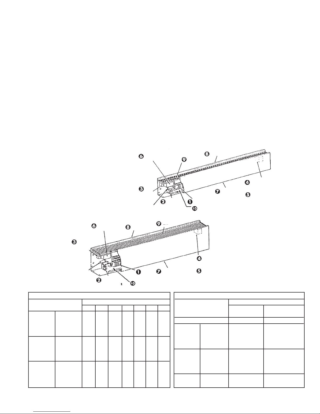
RENEWAL PARTS
IDENTIFICATION:
CSLAS, CSLAM, CSLAL
THERMOSTAT
(OPTIONAL)
DISCONNECT
SWITCH
(OPTIONAL)
ELEMENT BUSHING
1213-2000-001
OVERLOAD
PROTECTOR
GRILLE
HEATING
ELEMENT
WIREWAY COVER
BACK PANEL
FRONT
COVER
TRANSFORMER
RELAY
(OPTIONAL)
POWER RELAY
(OPTIONAL)
BACK PANEL
FRONT COVER
1402-0315-VAR (OSH07A)
1402-0314-VAR (OSH14A)
DISCONNECT
SWITCH
(OPTIONAL)
ELEMENT BUSHING
1213-2000-001
THERMOSTAT
(OPTIONAL)
OVERLOAD
PROTECTOR
4502-0007-VAR
GRILLE
HEATING
ELEMENT
WIREWAY COVER
6405-0053-VAR
Heater Element (Part No. Prefix 1802-2001)
Description Heater Length
28” 3’ 4’ 5’ 6’ 8’ 10’
125 W/ft. 120 Volts 085 087 089 091 093 – –
per 208 Volts 086 088 090 092 094 095 096
Element 240 Volts 048 054 060 066 072 077 081
277 Volts 049 055 061 067 073 078 082
188 W/ft. 120 Volts 005 011 017 023 029 – –
per 208 Volts 002 008 014 020 026 032 036
Element 240 Volts 001 007 013 019 025 031 035
277 Volts 000 006 012 018 024 030 034
250 W/ft. 120 Volts 004 010 016 022 028 ––
per 208 Volts 003 009 015 021 027 033 037
Element 240 Volts 002 008 014 020 026 032 036
277 Volts 001 007 013 019 025 031 035
TRANSFORMER
RELAY
(OPTIONAL)
POWER RELAY
(OPTIONAL)
Built-in Controls (Optional)
Description Part Number
CSLAM & CSLAS UNITS
CSLAL UNITS
Disconnect Switch 5216-0124-000 5216-0124-000
Transformer 120 Volts R13700002B001 410043001
Relay 208 Volts R13700002B002 410043002
240 Volts R13700002B003 410043003
277 Volts R13700002B004 410043004
Power 24 Volts 5018-2006-000 5018-2006-000
Relay 120 Volts 5018-2006-001 5018-2006-001
208/240 Volts 5018-2006-002 5018-2006-002
277 Volts 5018-2006-003 5018-2006-003
Thermostat 1 Pole 5813-0024-000 5813-0024-000
2 Pole 5813-0023-000 5813-0023-000
7
Page 8
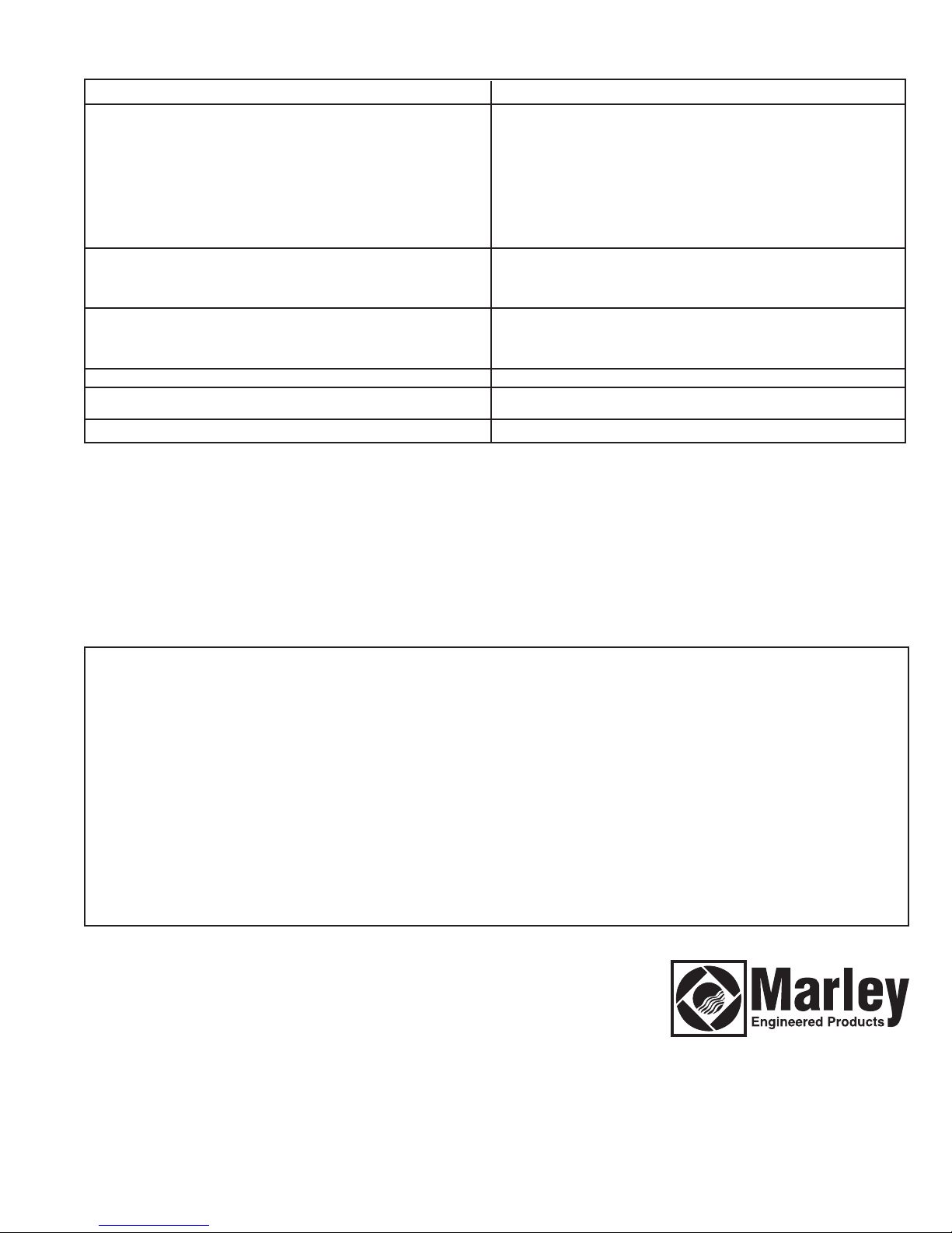
Renewal Parts Identification: Optional Controls: CSLAMBCS, CSLALBCS
Description Part Number
Mercury relay, 1 pole 30 amps, 24 Volt coil 5018-7050-001
Mercury relay, 1 pole 60 amps, 24 Volt coil 5018-7049-001
Mercury relay, 1 pole 30 amps, 120 Volt coil 5018-7050-002
Mercury relay, 1 pole 60 amps, 120 Volt coil 5018-7049-002
Mercury relay, 1 pole 30 amps, 208 Volt coil 5018-7050-003
Mercury relay, 1 pole 60 amps, 208 Volt coil 5018-7049-003
Mercury relay, 1 pole 30 amps, 240 Volt coil 5018-7050-004
Mercury relay, 1 pole 60 amps, 240 Volt coil 5018-7049-004
Mercury relay, 1 pole 30 amps, 277 Volt coil 5018-7050-005
Mercury relay, 1 pole 60 amps, 277 Volt coil 5018-7050-005
Circuit breaker, 2 pole 30 amps 1226-7009-013
Circuit breaker, 2 pole 60 amps 1226-7009-010
Circuit breaker, 3 pole 30 amps 1226-7009-005
Circuit breaker, 3 pole 60 amps 1226-7009-002
24V Transformer, 120 Volt primary 5814-7017-007
24V Transformer, 208 Volt primary 5814-7017-002
24V Transformer, 240 Volt primary 5814-7017-007
24V Transformer, 277 Volt primary 5814-7017-001
Disconnect Switch 5216-0124-000
Thermostat, 1 pole 5813-0024-000
Thermostat, 2 stage 5813-0023-000
Pneumatic Control 5216-7027-001
All products manufactured by Marley Engineered Products are warranted against defects in workmanship and materials for one year from date of installation, except
LIMITED WARRANTY
heating elements which are warranted against defects in workmanship and materials for five years from date of installation. This warranty does not apply to damage from
accident, misuse, or alteration; nor where the connected voltage is more than 5% above the nameplate voltage; nor to equipment improperly installed or wired or
maintained in violation of the product’s installation instructions. All claims for warranty work must be accompanied by proof of the date of installation.
The customer shall be responsible for all costs incurred in the removal or reinstallation of products, including labor costs, and shipping costs incurred to return products
to Marley Engineered Products Service Center. Within the limitations of this warranty, inoperative units should be returned to the nearest Marley authorized service center or the Marley Engineered Products Service Center, and we will repair or replace, at our option, at no charge to you with return freight paid by Marley. It is agreed that
such repair or replacement is the exclusive remedy available from Marley Engineered Products.
THE ABOVE WARRANTIES ARE IN LIEU OF ALL OTHER WARRANTIES EXPRESSED OR IMPLIED, AND ALL IMPLIED WARRANTIES OF MERCHANTABILITY AND
FITNESS FOR A PARTICULAR PURPOSE WHICH EXCEED THE AFORESAID EXPRESSED WARRANTIES ARE HEREBY DISCLAIMED AND EXCLUDED FROM
THIS AGREEMENT. MARLEY ENGINEERED PRODUCTS SHALL NOT BE LIABLE FOR CONSEQUENTIAL DAMAGES ARISING WITH RESPECT TO THE
PRODUCT, WHETHER BASED UPON NEGLIGENCE, TORT, STRICT LIABILITY, OR CONTRACT.
Some states do not allow the exclusion or limitation of incidental or consequential damages, so the above exclusion or limitation may not apply to you. This warranty gives
you specific legal rights, and you may also have other rights which vary from state to state.
For the address of your nearest authorized service center, contact Marley Engineered Products in Bennettsville, SC, at 1-800-642-4328. Merchandise returned to the factory must be accompanied by a return authorization and service identification tag, both available from Marley Engineered Products. When requesting return authorization,
include all catalog numbers shown on the products.
HOW TO OBTAIN WARRANTY SERVICE AND
WARRANTY PARTS PLUS GENERAL INFORMATION
1. Warranty Service or Parts
2. Purchase Replacement Parts
3. General Product Information
Note:
When obtaining service always have the following:
1. Model number of the product
2. Date of manufacture
3. Part number or description
1-800-642-4328
1-800-654-3545
www.marleymep.com
470 Beauty Spot Rd. East
Bennettsville, SC 29512 USA
Part No. 5200-2210-002
ECR 38636
12/10
Page 9

Convectores
Calefactores
comerciales a nivel
de convección comerciales a nivel de zócalo
(Tipo CSL)
de zócalo
Tipo CSL
Instrucciones de instalación, operación y mantenimiento
INSTRUCCIONES IMPORTANTES
Información general
Este calefactor está diseñado para proporcionar muchos años de funcionamiento eficiente y sin problemas como fuente de calor
principal o complementaria para calefacción ambiental, en aplicaciones residenciales (modelo CSLAS, 250 watts por pie máx. únicamente) y comerciales. La instalación o uso de este producto de cualquier manera no descrita en este manual anulará la garantía,
y podría provocar lesiones, daños materiales o daño permanente al calefactor.
ADVERTENCIA
AL UTILIZAR ARTEFACTOS ELÉCTRICOS, PARA REDUCIR
EL RIESGO DE INCENDIO, CHOQUE ELÉCTRICO Y
LESIONES PERSONALES DEBEN OBSERVARSE SIEMPRE
ALGUNAS PRECAUCIONES BÁSICAS, COMO LAS SIGUIENTES:
1. Lea todas las instrucciones antes de instalar o utilizar el
calefactor.
2. Un calefactor tiene en su interior piezas calientes, y piezas
en donde se producen arcos o chispas. No lo utilice en
áreas en las que se utilice o almacene gasolina o líquidos
inflamables. No lo utilice en entornos corrosivos ni en
ningún lugar en el que se utilicen o almacenen materiales
explosivos.
3. Cuando está en funcionamiento, el calefactor está muy
caliente. Para evitar quemaduras, no deje que su piel haga
contacto directo con las superficies calientes. Mantenga
RECEPCIÓN
Cuando el material se envió estaba en buenas condiciones, y
Marley Engineered Products cuenta con un conocimiento de
embarque limpio (sin objeciones), por lo que todo daño oculto
debe informarse enseguida al transportista para su inspección y
resolución.
!
lejos del calefactor los materiales combustibles como muebles, almohadas, ropas de cama, papeles, ropas y cortinas.
4. Para evitar un posible incendio, no bloquee de ningún modo
las entradas o la descarga de aire.
5. No inserte ni permita que entren objetos extraños en ninguna abertura de ventilación o de descarga, porque esto
puede ser causa de choque eléctrico, incendio o daño al
calefactor.
6. Un choque eléctrico podría producir lesiones graves o la
muerte. Asegúrese de que el circuito de alimentación eléctrica del calefactor esté desconectado en el tablero de servicio o desconectador principal, antes de instalar o prestar
servicio a este calefactor.
7. Este calefactor no es para uso residencial o doméstico,
excepto el modelo CSLAS con 820 watts por metro / 250
watts por pie.
Nota:
es aconsejable almacenar las cajas en un área central,
para enviar las unidades a las habitaciones a medida que lo
requieran. Si las cajas constituyen un pedido, estarán etiquetadas con el número correcto de la habitación.
GUARDE ESTAS INSTRUCCIONES
Page 10

ESPECIFICACIONES
Typo CSL
Figura 1
Tabla A
Modelo CSLAS (H = 5 1/2"; D = 3”)”)
Número de Longitud Watts Corriente, A
catálogo* “L” Watts/pie . totales 120 V 208 V 240 V 277 V
-2125 125 250 2.4 1.2 1.0 0.9
-2188 28” 188 375 3.1 1.8 1.6 1.4
-2250 250 500 4.2 2.4 2.1 1.8
-3125 125 375 3.1 1.8 1.6 1.4
-3188 3’ 188 564 4.7 2.7 2.4 2.0
-3250 250 750 6.2 3.6 3.1 2.7
-4125 125 500 4.2 2.4 2.1 1.8
-4188 4 188 750 6.2 3.6 3.1 2.7
-4250 250 1000 8.3 4.8 4.2 3.6
-5125 125 625 5.2 3.0 2.6 2.2
-5188 5 188 940 7.8 4.5 3.9 3.4
-5250 250 1250 10.4 6.0 5.2 4.5
-6125 125 750 6.2 3.6 3.1 2.7
-6188 6 188 1125 9.4 5.4 4.7 4.1
-6250 250 1500 12.5 7.2 6.2 5.4
-8125 125 1000 - 4.8 4.2 3.6
-8188 8’ 188 1500 - 7.2 6.2 5.4
-8250 250 2000 - 9.6 8.3 7.2
-10125 125 1250 - 6.0 5.2 4.5
-10188 10’ 188 1875 - 9.0 7.8 6.7
-10250 250 2500 - 12.0 10.4 9.0
Cuadro de espacios libres
Para garantizar un funcionamiento seguro y eficiente mantenga
como mínimo, en todo momento, los espacios libres que se indican
a continuación:
Del fondo del calefactor al piso terminado
Watts/pie de longitud
de los calefactores Enrada inferior Entrada frontal
125, 188 y 250 44 mm (1-3/4”) 0 mm (0”)
376 500, 625, y 750 76 mm (3”) 0 mm (0”)
Del extremo superior del calefactor al extremo inferior de los
cortinados situados arriba del calefactor:
Mínimo: 305 mm (12 pulgadas)
Nota importante:
sianas vinílicas) pueden sufrir daños por el aire caliente proveniente del
calefactor, y no deben instalarse sobre el mismo.
Del frente del calefactor a cortinados largos situados frente a él:
Mínimo entre el borde inferior de los cortinados y el piso: 64 mm
(21/2 pulgadas)
Mïnimo entre el borde superior de los cortinados y el cielorraso:
13 mm (1/2 pulgada)
Mïnimo entre el frente del calefactor y el pliegue más cercano del
cortinado: 51 mm (2 pulgadas)
Del extremo superior del calefactor al extremo inferior del
alféizar de una ventana:
Mínimo: 305 mm (12 pulgadas)
algunas telas y materiales vinílicos (como las per-
Tabla A (continuación)
Modelo CSLAM (H = 7”; D = 5”)
Modelo CSLAL (H = 14”; D = 5”)
Corriente, A
Número de Longitud Watts 208 V 240 V 277 V
catálogo** “L” Watts/pie totales 1Ø 3Ø 1Ø 3Ø 1Ø
-2125 125 250 1.2 - 1.0 - 0.9
-2188 188 375 1.8 - 1.6 - 1.4
-2250 250 500 2.4 - 2.1 - 1.8
-2375 28” 375 750 3.6 - 3.1 - 2.7
-2500 500 1000 4.8 - 4.2 - 3.6
-2564 564 1125 5.4 3.1 4.7 2.7 4.0
-2625 625 1250 6.0 3.5 5.2 3.0 4.5
-2750 750 1500 7.2 4.2 6.2 3.6 5.4
-3125 125 375 1.8 - 1.6 - 1.4
-3188 188 564 2.7 - 2.4 - 2.0
-3250 250 750 3.6 - 3.1 - 2.7
-3375 3’ 375 1125 5.4 - 4.7 - 4.0
-3500 500 1500 7.2 - 6.2 - 5.4
-3564 564 1690 8.1 4.7 7.4 4.3 6.1
-3625 625 1875 9.0 5.2 7.8 4.5 6.7
-3750 750 2250 11.0 6.5 9.4 5.4 8.1
-4125 125 500 2.4 - 2.1 - 1.8
-4188 188 750 3.6 - 3.1 - 2.7
-4250 250 1000 4.8 - 4.2 - 3.6
-4375 4’ 375 1500 7.2 - 6.2 - 5.4
-4500 500 2000 9.6 - 8.3 - 7.2
-4564 564 2250 10.8 6.2 9.4 5.4 8.0
-4625 625 2500 12.0 6.9 10.4 6.0 9.0
-4750 750 3000 14.4 8.3 12.5 7.2 10.8
-5125 125 625 3.0 - 2.6 - 2.2
-5188 188 940 4.5 - 3.9 - 3.4
-5250 250 1250 6.0 - 5.2 - 4.5
-5375 5’ 375 1875 9.0 - 7.8 - 6.7
-5500 500 2500 12.0 - 10.4 - 9.0
-5564 564 2820 13.5 7.8 11.8 6.8 10.2
-5625 625 3125 15.0 8.7 13.0 7.5 11.3
-5750 750 3750 18.0 10.4 15.6 9.0 13.5
-6125 125 750 3.6 - 3.1 - 2.7
-6188 188 1125 5.4 - 4.7 - 4.0
-6250 250 1500 7.2 - 6.2 - 5.4
-6375 6’ 375 2250 10.8 - 9.4 - 8.1
-6500 500 3000 14.4 - 12.5 - 10.8
-6564 564 3380 16.2 9.4 14.1 8.1 12.2
-6625 625 3750 18.0 10.4 15.6 9.0 13.5
-6750 750 4500 21.6 12.5 18.7 10.8 16.2
-8125 125 1000 4.8 - 4.2 - 3.6
-8188 188 1500 7.2 - 6.2 - 5.4
-8250 250 2000 9.6 - 8.3 - 7.2
-8375 8’ 375 3000 14.4 - 12.5 - 10.8
-8500 500 4000 19.2 - 16.7 - 14.4
-8564 564 4500 21.6 12.5 18.7 10.8 16.2
-8625 625 5000 24.0 13.9 20.8 12.0 18.0
-8750 750 6000 28.6 16.5 15.0 14.4 21.6
-10125 125 1250 6.0 - 5.2 - 4.5
-10188 188 1875 9.0 - 7.8 - 6.7
-10250 250 2500 12.0 - 10.4 - 9.0
-10375 10’ 375 3750 18.0 - 15.6 - 13.5
-10500 500 5000 24.0 - 20.8 - 18.0
-10564 564 5640 27.2 15.7 23.5 13.6 20.4
-10625 625 6250 30.0 17.3 26.0 15.0 22.6
-10750 750 7500 36.0 20.8 31.3 18.1 27.0
INSTRUCCIONES DE INSTALACIÓN
10
Page 11

PARA REDUCIR EL PELIGRO DE INCENDIO, CHOQUE ELÉCTRICO O DAÑO A LAS PERSONAS, OBSERVE LO SIGUIENTE::
1. Antes de instalar este calefactor, extraiga y deseche las almohadillas de embalaje que están dentro del mismo. Revise el calefactor para asegurarse de que no esté dañado.
2. Un choque eléctrico podría producir lesiones graves o la muerte.
Asegúrese de que el circuito de alimentación eléctrica del calefactor esté desconectado en el tablero de servicio o desconectador principal, antes de instalar este calefactor.
3. Los procedimientos de cableado y las conexiones deben estar
de acuerdo con el Código Eléctrico Nacional (NEC) de los EE.
UU. y los códigos locales. Consulte el Diagrama de conexionado
que está en el calefactor y en la Figura 9. Asegúrese de que
todas las conexiones eléctricas estén firmes, para evitar posibles
sobrecalentamientos. Utilice cables de alimentación de cobre
únicamente.
4. Verifique que la tensión de alimentación eléctrica coincida con la
tensión nominal que está impresa en la placa de características
del calefactor.
PRECAUCIÓN:
no conecte nunca un calefactor a una tensión mayor
que la nominal que se indica en la placa de características, ya
que esto dañará el calefactor y podría originar un incendio.
5. No instale el calefactor contra superficies de tableros combustibles de fibra de celulosa de baja densidad, contra o debajo
de revestimientos de pared vinílicos, ni debajo de ningún material que pueda dañarse por el calor, como cortinas o persianas
vinílicas o plásticas, etc.Si el calefactor se va a instalar contra
revestimientos de pared vinílicos deben utilizarse los Juegos de
soporte separador, Nº de catálogo SO1 o SO2. Vea las instrucciones que se proporcionan con los juegos.
6. No instale el calefactor debajo de un tomacorriente eléctrico.
PRECAUCIÓN:
el calefactor funciona a altas temperaturas.
Mantenga los cordones eléctricos (incluidos los cables de teléfono y de computadora), cortinados y otros elementos del mobiliario, alejados del calefactor. Para garantizar un funcionamiento
eficiente y seguro, recomendamos mantener en todo momento
un espacio libre de 152 mm (6 pulgadas) como mínimo por encima y frente al calefactor.
7. Para reducir el riesgo de incendio, no almacene ni use gasolina
u otros vapores y líquidos inflamables en las cercanías del calefactor.
8. No instale el calefactor en posición invertida ni en cualquier otra
posición diferente de la que se muestra en esta hoja de instrucciones. La etiqueta de precaución con la palabra ‘ARRIBA’
(‘TOP’) debe quedar en la parte superior cuando se instale el
calefactor.
9. No instale el calefactor embutido en la pared ni dentro de gabinetes de ningún tipo, ya que esto hará que se sobrecaliente, lo
que podría crear un riesgo.
10. Al montar el calefactor, tenga cuidado al sujetarlo a la estructura
del edificio y evite dañar sus componentes internos.
11. No retire ni puentee el control de límite de seguridad (protector
térmico), ya que esto podría crear en el calefactor un riesgo de
incendio; vea el diagrama de conexionado del calefactor, que se
suministra con él.
12. Los cables instalados en fábrica dentro del canal de cables se
utilizan para conectar los controles incorporados. Limite la corriente máxima a no más de 45 amperes en total. Consulte las
instrucciones y los valores nominales de capacidad de corriente
que se suministran con el accesorio.
13. Los calefactores que no están instalados extremo a extremo
deben tener tapas extremas instaladas, para cubrir los extremos
expuestos de cada calefactor.
14. Todo el conexionado del sitio que llega al calefactor debe ser
apto para 75 ºC como mínimo.
15. No permita la colocación de objetos sobre el calefactor, ya que
pueden dañarse o crear un riesgo de incendio.
16. Antes de energizarlo, asegúrese de que el calefactor esté completamente montado, con la rejilla, la cubierta frontal, las tapas
extremas y los accesorios que se hubieran instalado.
Cableado de instalación
1. Realice el tendido de un circuito de derivación, de la tensión y calibre de cables adecuado, hasta la ubicación de la caja de conexiones izquierda o derecha, como se indica en el diagrama de conexionado del calefactor. Los calefactores básicos están precableados y
pueden conectarse al circuito de derivación por cualquiera de sus
extremos. Los calefactores con controles están precableados para
su conexión al circuito de derivación por uno solo de sus extremos
(consulte el diagrama de conexionado del calefactor); sin embargo,
el calefactor puede cablearse a partir del extremo opuesto si se
tiende el cable a través del canal de cables del calefactor.
2. Si fuera necesario tender cables por el canal de cables del calefactor, utilice la Tabla B para dimensionar el conexionado instalado en
el sitio.
3. Los cables instalados en fábrica en el canal de cables del calefactor
pueden cargarse hasta 45 A. Para conocer la longitud máxima del
tramo de calefactores cuando se los conecta en paralelo, consulte la
Tabla C.
Termostato
24 A @ 120-240 V CA
22 A @ 277 V CA
Servicio auxiliar – 125 V CA
(todas las tensiones)
Relé con transformador
Unidades 05A: 22 A @ 120-240 V CA
19 A @ 277 V CA
Unidades 07A-14A: 25 A @ 120-240 V CA
22 A @ 277 V CA
Relé de potencia
Interruptor de desconexión
25 A @ 120-277 V CA; vea el diagrama de
conexionado en el calefactor
20 A @ 120-277 V CA
Tabla B. Dimensionamiento del conexionado
instalado en el sitio
Calibre de Cantidad máx.
cable de de cables Hasta 3 4 a 6 7 a 9
cobre, 75 ºC en el canal conductores conductores conductores
No. 12 AWG 9 11.5 amperes 9.3 amperes 8.1 amperes
No. 10 AWG 8 17.4 amperes 14.0 amperes 12.1 amperes
No. 8 AWG 4 24.0 amperes 21.0 amperes –
Corriente máxima admisible
Tabla C. Longitud máxima del tramo de calefactores (CSLAS,
monofásico)
Watts/pie de los
calefactores 120 volts 208 volts 240 volts 277 volts
125 33 58 67 77
188 22 38 44 51
250 16 29 33 38
Nota:
para casos de mezcla de densidades de potencia, calcule el consumo de
corriente. No supere los valores indicados en el paso 3 anterior.
Longitud máxima admisible del tramo de calefactores (pies
)
Tabla D. Longitud máxima del tramo de calefactores
(CSLAM y CSLAL)
Watts/pie
de los
calefactores
125 74 - 86 - 99
188 49 - 57 - 66
250 37 - 43 - 49
376 24 - 28 - 33
500 18 - 21 - 24
564 16 27 19 32 22
625 15 24 17 29 20
750 12 20 14 24 16
Longitud máxima admisible del tramo de calefactores en pies (metros)
208 V 240 V 277 V
1 Monof. 3 Trif. 1 Monof. 3 Trif. 1 Monof.
11
Page 12

4. Deben utilizarse cables estándar de 75 ºC en cajas de conexiones,
H
EATER
H
EATERS
BUTTED
TOGETHER
H
EATER
F
ILLER
S
ECTION
H
EATER
I
NSIDE
C
ORNER
H
EATER
OUTSIDE
CORNER
HEATER
E
ND
CAP
TYPICAL INSTALLATION
S
PLICE PLATE
KIT
S
PLICE PLATE
KIT
canales de cables, secciones vacías, secciones de relleno y secciones de esquina.
Disposición en la habitación
Para ver los arreglos exactos de los calefactores en la habitación, vea
los planos de calefacción (con o sin termostato y/o relés y/o interruptores y accesorios).
Antes de comenzar una instalación del tipo de pared a pared identifique
las dimensiones de la sección de calefactores y la longitud de pared
adicional requeridas para los accesorios de extensión (Figura 2).
Asegúrese de que todos los calefactores y accesorios necesarios estén
a mano y tengan el acabado correcto.
10
JUEGO DE PLACAS DE
N
UNIÓN
N
N
N
ANEL POSTERIOR
P
/4”
3
2-15/16”
-1/4”
1
CONCÉNTRICOS DE 29 mm
(1-1/8”) Y 22 mm (7/8”) DE DIÁM.
1-7/16”
1-7/16”
PREPUNZONADOS
PREPUNZONADOS
CONCÉNTRICOS DE 22 mm (7/8”) Y
29 mm (1-1/8”) DE DIÁM.
ANEL POSTERIOR
P
B
A
1-15/16”
-1/4”
1
CONCÉNTRICOS DE 35 mm (1-3/8”)
1-9/16”
-1/2”
2
3/4”
PREPUNZONADOS
Y 44.5 mm (1-3/4”) DE DIÁM.
10
JUEGO DE PLACAS DE
N
CALEFACTOR
9
UNIÓN
CAPUCHON
D’EXTRÉMITÉ
6
CALEFACTOR
7
CALEFAC-
TORES JUNTA-
DOS A TOPE
CALEFACTOR
Figura 2
Instalación típica
Vea las dimensiones N
en la página 8
3
SECCIÓN DE
RELLENO
1
CALEFACTOR
2
ANGLE
RENTRANT
CALEFACTOR
8
ANGLE
SORTANT
5
4
N
Instalación de una sola unidad
Nota:
para facilitar la instalación es importante seguir en orden la
secuencia de operaciones que se indica a continuación.
1. Retire la cubierta frontal; para ello quite los tornillos de montaje
(Figura 3).
2. Extraiga el prepunzonado eléctrico apropiado de una de las cajas
de conexiones. Vea las ubicaciones de los prepunzonados en la
Figura 4.
SECCIÓN DE
RELLENO
RECORTE ESTA
PORCIÓN SI FUERA
NECESARIO
TAPA EXTREMA DE LA
SECCIÓN DE RELLENO
TORNILLOS DE
MONTAJE PARA
ACCESORIOS
AGUJEROS DE
MONTAJE DEL
CALEFACTOR
AGUJEROS DE MONTAJE
PARA ACCESORIOS
GABINETE
TORNILLOS DE
PUESTA A TIERRA
PREPUNZONADOS CONCÉN-
TRICOS DE 35 mm (1-3/8”) Y 29
mm (1-1/8”) DE DIÁM.
VISTA INFERIOR
PREPUNZONADOS
CONCÉNTRICOS DE 35 mm (1-3/8”)
Y 44.5 mm (1-3/4”) DE DIÁM.
VISTA INFERIOR
CSLAM CSLAL
A
B
4”
N/D
5”
5”
Figura 4
3. Instale las tapas extremas (deben comprarse por separado) en
ambos extremos del gabinete del calefactor. Para ver los detalles de
la instalación de las tapas extremas consulte la Figura 5.
4. Si se desea una sección de relleno como terminación del calefactor,
instale la sección de relleno en el extremo del calefactor y extiéndala hasta la longitud deseada. Marque las ubicaciones de los agujeros de montaje, retire la sección de relleno y perfore los agujeros
de montaje requeridos. Instale la sección de relleno en el calefactor
y la tapa extrema en la sección de relleno, como se muestra en la
Figura 3.
Nota:
si se instala un termostato y/o un interruptor de desconexión en la
caja de conexiones izquierda del calefactor, puede que sea necesario
recortar una porción de la sección de relleno para permitir el acceso a
estos controles (Figura 3).
5 Coloque el gabinete del calefactor en la pared para verificar la uni-
formidad de la misma. No lleve el calefactor contra una superficie de
pared que sea irregular. Si se encuentra una pared irregular, utilice
suplementos para mantener recto el gabinete del calefactor.
6. Realice el tendido de un circuito de derivación del calibre
adecuado hasta la caja de conexiones, a través del prepunzonado
seleccionado.
CUBIERTA
TORNILLOS DE
MONTAJE DE
LA CUBIERTA
TORNILLOS DE MONTAJE
DE LA CUBIERTA
PERFORE AGUJEROS (PARA EL MONTAJE
DEL CALEFACTOR Y PARA INSTALAR LA SECCIÓN DE RELLENO) SEGÚN SEA NECESARIO.
ENTRADA INFERIOR
ENTRADA FRONTAL
Figura 3
GABINETE
CUBIERTA (ENTRADA FRONTAL)
GABINETE
TORNILLOS
DE MONTAJE
TAPA
EXTREMA
AGUJEROS DE
MONTAJE PARA
ACCESORIOS
TAPA
EXTREMA
Figura 5
12
Page 13

7. Perfore los agujeros de montaje del tamaño necesario en el dorso
del gabinete del calefactor e instale el gabinete en la pared mediante tornillos, pernos o anclajes (a suministrar por el instalador) que
sean adecuados para la construcción de la pared.
Nota:
en cada caja de conexiones se proporcionan agujeros de montaje
pre-perforados de 6.4 mm (1/4”) de diámetro. Se deberán perforar
agujeros de montaje adicionales en el gabinete para sostener el peso
de los calefactores más largos (de 1.83 m / 6 pies o mayores). No
perfore agujeros adicionales en las cajas de conexiones.
8. Apriete los tornillos de montaje y luego retroceda de ¼ a ¾ de
vuelta para permitir la expansión y contracción del calefactor.
9. Haga las conexiones eléctricas de acuerdo con el diagrama de
conexionado que está sujeto al calefactor. Conecte el calefactor a
tierra mediante los tornillos de puesta a tierra provistos (Figura 3).
10. Vuelva a colocar la cubierta frontal y sujétela con los tornillos de
montaje (vea la Figura 3).
Instalación de unidades múltiples de pared a pared
Nota:
para facilitar la instalación es importante seguir en orden la
secuencia de operaciones que se indica a continuación.
1. Retire todas las cubiertas frontales de los calefactores; para ello
quite los tornillos de montaje (Figura 3).
2. Consulte el diagrama de conexionado para ver cómo es la entrada
de la alimentación eléctrica, y extraiga el prepunzonado eléctrico
apropiado (Figura 4) del calefactor en el que va a hacer las conexiones de alimentación eléctrica. La conexión de alimentación eléctrica puede llevarse sólo hasta el extremo de un calefactor, y los calefactores restantes pueden conectarse en paralelo mediante el canal
de cables. Para dimensionar el conexionado instalado en el sitio en
el canal de cables, utilice la Tabla B.
3. Si se desea colocar la cubierta del canal (debe comprarse por sepa-
rado), corte la longitud apropiada e instálela contra la pared.
4. Si el plano lo requiere, sujete la sección de relleno (1) (Figura 1) a
uno de los calefactores (2) o (3) mediante 4 tornillos Nº 6 suministrados con la sección de relleno (consulte la Figura 6). Deseche la
tapa extrema de la sección de relleno en esta aplicación.
Nota:
si se desea, los calefactores pueden juntarse a tope entre sí, con
lo que se elimina la pieza de relleno.
LA SECCIÓN DE RELLENO
SE DESLIZA DENTRO DEL
CALEFACTOR DE 13 mm
(1/2”) A 88.9 mm (3-1/2”)
Nota:
si un calefactor tiene un interruptor de desconexión y/o un termostato, y va a tener una sección de relleno o una sección de esquina
en el extremo izquierdo, la sección debe montarse en el calefactor,
dado que el termostato o el interruptor de desconexión impedirán que la
sección se extienda hasta el calefactor.
5 Si el tramo de pared tiene esquinas interiores o exteriores, instale la
esquina (4 y 5) en el calefactor (2 y 9) mediante 4 tornillos Nº 6
suministrados con la sección de la esquina (consulte la Figura 6).
6. Instale las tapas extremas (6) en el extremo exterior del último
calefactor (7 y 9) mediante 4 tornillos Nº 6 suministrados con las
tapas extremas (para ver los detalles de la instalación de las tapas
extremas consulte la Figura 5).
7. Perfore los agujeros de montaje del tamaño requerido en todos los
gabinetes de los calefactores.
Nota:
en cada caja de conexiones se proporcionan agujeros de montaje
pre-perforados de 6.4 mm (1/4”) de diámetro. Estos agujeros pueden
utilizarse únicamente cuando no se vaya a instalar ningún accesorio
deslizante en ese extremo del calefactor, como cuando se juntan
calefactores a tope (3 y 7) según se muestra en la Figura 2. Se deberán
perforar agujeros de montaje adicionales en el gabinete para sostener el
peso de los calefactores más largos (de 1.83 m / 6 pies o mayores). No
perfore agujeros adicionales en las cajas de conexiones.
8. Verifique la uniformidad de la pared. No lleve los calefactores con-
tra una superficie de pared que sea irregular. Si se encuentra una
pared irregular, utilice suplementos para mantener recto el gabinete del calefactor.
9. Realice el tendido de un circuito de derivación del calibre adecua-
do hasta la caja de conexiones, a través del prepunzonado seleccionado.
10. Monte el calefactor (2, Figura 2) contra la pared mediante tornillos,
pernos o anclajes (a suministrar por el instalador) que sean adecuados para la construcción de la pared.
11. Extienda el gabinete del calefactor (3) sobre la sección de relleno
(1) en la cantidad deseada, y monte el gabinete en la pared.
12. Extienda el gabinete del calefactor (8) sobre la sección de esquina
(4) en la cantidad deseada, y monte el gabinete en la pared.
13. Monte los calefactores restantes como se describió antes;
asegúrese de que los calefactores con tapas extremas se instalen
en el extremo del tramo.
14. Las secciones vacías, si las hay, se instalan del mismo modo que
los calefactores.
Nota:
los cables de 75 ºC del conexionado del sitio puede tenderse a
través de las secciones vacías, secciones de relleno y secciones de
esquina.
15. Las secciones de control, si las hay, se instalan del mismo modo
que los calefactores. Para la conexión del cableado que va a los
calefactores, consulte el diagrama de conexionado de las secciones de control.
SECCIÓN DE
RELLENO
SECCIÓN DE
ESQUINA
CALEFACTOR
Figura 6
CALEFACTOR
TORNILLOS DE MONTAJE
PARA ACCESORIOS
CALEFACTOR
TORNILLOS DE MONTAJE
PARA ACCESORIOS
Instalación de unidades de montante a montante
El dorso del gabinete del calefactor no contiene agujeros de montaje
(además de los que están en los extremos), y por lo tanto es ideal para
la instalación frente a paredes de cortina de vidrio. El dorso del gabinete
presenta un aspecto atractivo cuando se lo ve desde el exterior a través
de la pared de vidrio. Los procedimientos de instalación son similares a
los de la instalación de pared a pared (paso 6), excepto por las
siguientes diferencias.
Installation procedures are similar to those for wall-to-wall installation
(Step Six) except for the following differences.
1. Sujete el gabinete al montante por medio de los agujeros de monta-
je provistos en las cajas de conexiones, como se muestra en la
Figura 7.
2. En instalaciones en montantes horizontales, instale escuadras de
soporte como se muestra en la Figura 8.
13
Page 14

INSTRUCCIONES DE OPERACIÓN
1. Este calefactor debe instalarse correctamente antes de usarlo.
2. Si el calefactor está equipado con un termostato incorporado, ajuste
el eje del mismo en una posición intermedia y deje que el calefactor
funcione durante unas horas. Si la temperatura de la habitación es
demasiado alta haga girar el eje en sentido antihorario, y si es
demasiado baja hágalo girar en sentido horario, hasta obtener una
temperatura confortable. Deje que la temperatura de la habitación
se estabilice después de cada nuevo ajuste. El calefactor hará ciclos
automáticos alrededor de este valor de ajuste del termostato.
Nota: si se proporciona un termostato o un interruptor de desconexión
en el calefactor, estos componentes son accesibles a través de las
aberturas de la rejilla que están en los extremos izquierdo y derecho del
calefactor.
MONTANTE
VERTICAL
VISTA FRONTAL
TORNILLOS (A
SUMINISTRAR
POR TERCEROS)
LÍNEA DEL PISO
VISTA SUPERIOR
Figura 7
MONTANTE
HORIZONTAL
Figura 8
TORNILLOS (A
SUMINISTRAR
POR TERCEROS)
ESCUADRA DE SOPORTE (A
SUMINISTRAR POR TERCEROS)
VISTA LATERAL
INSTRUCCIONES DE MANTENIMIENTO
Para garantizar un funcionamiento eficiente y seguro y para extender la
vida útil de los calefactores, estos deben limpiarse e inspeccionarse
para ver si presentan daños una vez al año como mínimo (preferiblemente el comienzo de la temporada de uso del calefactor), o más a
menudo en entornos muy cargados de suciedad. Sus calefactores no
requieren ningún otro mantenimiento preventivo que la limpieza.
1. Un choque eléctrico podría producir lesiones graves o la muerte.
Asegúrese de que el (los) circuito(s) de alimentación eléctrica del
calefactor esté(n) desconectado(s) en el tablero de servicio o
desconectador principal, antes de prestar servicio a este calefactor. Deje enfriar el calefactor antes de limpiarlo, para prevenir una
posible quemadura.
Nota:
puede ingresar al calefactor más de una fuente de alimentación. Asegúrese de que toda la alimentación eléctrica esté
desconectada antes de la limpieza o el servicio.
2. Tenga cuidado al limpiar las aletas de los elementos calefactores,
para evitar dañarlas. Note también que las aletas son aguzadas y
pueden causar cortes; por eso, evite el contacto.
1. El usuario puede realizar una limpieza periódica del gabinete exterior. Los demás servicios deben estar a cargo de personal de servicio
calificado.
2. El gabinete del calefactor puede limpiarse con un paño húmedo
para eliminar el polvo que pueda haberse acumulado en las superficies. No utilice limpiadores o ceras agresivas en las superficies, ya
que podrían dañar el acabado o alterar el color durante el uso.
3. Para eliminar el polvo y la pelusa que se podrían haber acumulado
dentro del calefactor y alrededor de las aletas de los elementos
calefactores, puede utilizarse una aspiradora y/o aire comprimido. Si
se debe desmontar el calefactor para la limpieza, tenga cuidado al
limpiar las aletas del elemento calefactor para evitar dañarlas.
4. Después de la limpieza y del servicio, vuelva a montar la unidad
cuidando de colocar todos los accesorios de montaje que se
quitaron, restablezca la alimentación eléctrica, y haga una revisión
para asegurarse de que los calefactores estén funcionando correctamente.
Nota importante:
suministran dentro de los calefactores, incluidos uno o más controles de
límite de sobretemperatura (protector térmico). Vea en el Diagrama de
conexionado del calefactor los controles específicos provistos. Estos
controles de seguridad se proporcionan para apagar el calefactor, si
fuera necesario, a fin de mantener temperaturas seguras en caso de un
bloqueo u otra condición anormal. NO puentee ni retire estos importantes controles de seguridad, ya que se suministran para limitar las
temperaturas y evitar un posible incendio en caso de que el calefactor
esté sometido a una condición de sobrecalentamiento. Si se determina
que el calefactor está haciendo ciclos de apagado por medio de los controles de seguridad en el uso normal, descontinúe el uso del calefactor
hasta que pueda ser inspeccionado y reparado por personal de servicio
calificado.
existen dispositivos de seguridad incorporados que se
Figura 9 - Diagrama de conexionado
CONEXIONADO TÍPICO DE CALEFACTORES MÚLTIPLES (SIN CONTROLES)
PROTECTOR
TÉRMICO
A OTRO
CALEFACTOR
ALIMENTACIÓN ELÉCTRICA AL INTERRUPTOR DE
DESCONEXIÓN
ELEMENTOS CALEFACTORES
TORNILLO DE
PUESTA A TIERRA
CABLE Nº 10 CABLE Nº 10
NOTA : para ver el conexionado interno individual del
calefactor, consulte la etiqueta del diagrama de conexionado de la unidad.
TORNILLO DE
PUESTA A TIERRA
SECCIÓN DE
RELLENO
14
PROTECTOR
TÉRMICO
ELEMENTOS CALEFACTORES
TORNILLO DE
PUESTA A TIERRA
TORNILLO DE
PUESTA A TIERRA
A OTRO
CALEFACTOR
CONEXIONADO DE FÁBRICA
CONEXIONADO DEL SITIO
Page 15

IDENTIFICACIÓN DE
PIEZAS PARA
RENOVACIÓN:
CSLAS, CSLAM, CSLAL
TERMOSTATO
(OPCIONAL)
INTERRUPTOR DE
DESCONEXIÓN
(OPCIONAL)
MANGUITO AIS-
LANTE DEL ELEMEN-
TO CALEFACTOR
1213-2000-001
PROTECTOR DE
SOBRECARGA
4502-0007-VAR
TERMOSTATO
(OPCIONAL)
INTERRUPTOR DE
DESCONEXIÓN
(OPCIONAL)
MANGUITO AISLANTE DEL
ELEMENTO CALEFACTOR
1213-2000-001
REJILLA
ELEMENTO
CALEFAC-
TOR
WIREWAY COVER
6405-0053-VAR
REJILLA
PROTECTOR
DE SOBRE-
CARGA
PANEL
POSTERIOR
CUBIERTA
FRONTAL
1402-0315-VAR (OSH07A)
1402-0314-VAR (OSH14A)
ANEL
P
OSTERIOR
P
ELEMENTO
CALEFACTOR
CUBIERTA DEL
CANAL DE CABLES
RELÉ CON
TRANSFORMADOR
(OPCIONAL)
RELÉ DE POTENCIA
(OPCIONAL)
CUBIERTA
FRONTAL
RELÉ CON
TRANSFORMADOR
(OPCIONAL)
RELÉ DE POTENCIA
(OPCIONAL)
Elemento calefactor (prefijo del Nº de parte: 1802-2001)
Descripción Longitud del calefactor
28” 3’ 4’ 5’ 6’ 8’ 10’
125 W/pie 120 volts 085 087 089 091 093 – –
por 208 volts 086 088 090 092 094 095 096
elemento 240 volts 048 054 060 066 072 077 081
277 volts 049 055 061 067 073 078 082
188 W/pie. 120 volts 005 011 017 023 029 – –
por 208 volts 002 008 014 020 026 032 036
elemento 240 volts 001 007 013 019 025 031 035
277 volts 000 006 012 018 024 030 034
250 W/pie. 120 volts 004 010 016 022 028 ––
por 208 volts 003 009 015 021 027 033 037
elemento 240 volts 002 008 014 020 026 032 036
277 volts 001 007 013 019 025 031 035
Controles incorporados (opcionales)
Descripción Número de parte
UNIDADES UNIDADES CSLAS
CSLAM y CSLAL
Interruptor de desconexión 5216-0124-000 5216-0124-000
Relé con 120 volts R13700002B001 410043001
transformador: 208 volts R13700002B002 410043002
240 volts R13700002B003 410043003
277 volts R13700002B004 410043004
Relé de 24 volts 5018-2006-000 5018-2006-000
potencia 120 volts 5018-2006-001 5018-2006-001
208/240 volts 5018-2006-002 5018-2006-002
277 volts 5018-2006-003 5018-2006-003
Termostato 1 Polo 5813-0024-000 5813-0024-000
2 Polos 5813-0023-000 5813-0023-000
15
Page 16

Identificación de piezas para renovación: Controles opcionales - CSLAMBCS, CSLALBCS
Descripción Número de parte
Relé de mercurio, 1 polo, 30 A, bobina de 24 volts 5018-7050-001
Relé de mercurio, 1 polo, 60 A, bobina de 24 volts 5018-7049-001
Relé de mercurio, 1 polo, 30 A, bobina de 120 volts 5018-7050-002
Relé de mercurio, 1 polo, 60 A, bobina de 120 volts 5018-7049-002
Relé de mercurio, 1 polo, 30 A, bobina de 208 volts 5018-7050-003
Relé de mercurio, 1 polo, 60 A, bobina de 208 volts 5018-7049-003
Relé de mercurio, 1 polo, 30 A, bobina de 240 volts 5018-7050-004
Relé de mercurio, 1 polo, 60 A, bobina de 240 volts 5018-7049-004
Relé de mercurio, 1 polo, 30 A, bobina de 277 volts 5018-7050-005
Relé de mercurio, 1 polo, 60 A, bobina de 277 volts 5018-7050-005
Interruptor automático, 2 polos, 30 A 1226-7009-013
Interruptor automático, 2 polos, 60 A 1226-7009-010
Interruptor automático, 3 polos, 30 A 1226-7009-005
Interruptor automático, 3 polos, 60 A 1226-7009-002
Transformador 24 V, primario 120 V 5814-7017-007
Transformador 24 V, primario 208 V 5814-7017-002
Transformador 24 V, primario 240 V 5814-7017-007
Transformador 24 V, primario 277 V 5814-7017-001
Interruptor de desconexión 5216-0124-000
Termostato, 1 polo 5813-0024-000
Termostato, 2 etapas 5813-0023-000
Control neumático 5216-7027-001
Todos los productos fabricados por Marley Engineered Products están garantizados contra defectos de fabricación y de materiales por 1 año desde la fecha de
GARANTÍA LIMITADA
instalación,
instalación.
nominal -indicada en la placa de características- en más de 5 %, ni a equipos que hayan sido instalados o cableados incorrectamente, o mantenidos en forma
que no cumpla lo indicado en las instrucciones de instalación del producto. Todo reclamo por trabajos en garantía debe acompañarse con una prueba de la fecha
de instalación.
El cliente será responsable de todos los costos incurridos en el retiro o reinstalación de productos, incluyendo los costos de mano de obra y los costos de envío
incurridos para regresar productos a un Centro de Servicio de Marley Engineered Products. Dentro de las limitaciones de esta garantía, las unidades que no
funcionan deben regresarse al centro de servicio autorizado Marley más cercano, o al Centro de Servicio de Marley Engineered Products, y nosotros lo
repararemos o reemplazaremos, a nuestra opción, sin cargo para usted, con el flete de retorno pagado por Marley. Se acuerda que tal reparación o reemplazo
es el único recurso que Marley Engineered Products pone a su disposición.
LAS GARANTÍAS EXPUESTAS MÁS ARRIBA TOMAN EL LUGAR DE TODA OTRA GARANTÍA, EXPRESA O IMPLÍCITA, Y POR LA PRESENTE SE
DECLINA Y EXCLUYE DE ESTE ACUERDO TODA GARANTÍA IMPLÍCITA DE COMERCIABILIDAD Y ADECUACIÓN A UN PROPÓSITO PARTICULAR QUE
EXCEDA LAS GARANTÍAS EXPRESAS ANTEDICHAS. MARLEY ENGINEERED PRODUCTS NO SE HARÁ RESPONSABLE POR DAÑOS CONSIGUIENTES
QUE SE PRODUZCAN CON RESPECTO AL PRODUCTO, EN BASE YA SEA A NEGLIGENCIA, AGRAVIO, RESPONSABILIDAD ESTRICTA, O CONTRATO.
Algunos estados o jurisdicciones no permiten la exclusión o limitación de daños incidentales o consiguientes, de modo que la exclusión o limitación expresada
más arriba puede no aplicarse a su caso. Esta garantía le da derechos legales específicos, y usted puede tener también otros derechos, que varían de un estado o jurisdicción a otro.
Para obtener la dirección de su centro de servicio autorizado más cercano comuníquese con Marley Engineered Products en Bennettsville, SC, Estados Unidos,
llamando al 1-800-642-4328. Toda mercadería regresada a la fábrica debe ser acompañada por una autorización de retorno y una etiqueta de identificación de
servicio, disponibles ambas en Marley Engineered Products. Cuando solicite la autorización de retorno, incluya todos los números de catálogo mostrados en los
productos.
CÓMO OBTENER SERVICIO EN GARANTÍA, PIEZAS DE
REPUESTO E INFORMACIÓN GENERAL
1. Servicio o repuestos en garantía
2. Compra de repuestos
3. Información general sobre productos
Nota:
1. Número de modelo del producto
2. Fecha de fabricación
3. Número de parte o descripción
excepto los elementos calefactores los cuales están garantizados contra defectos en manufactura y materiales durante cinco años a partir de la fecha de
Esta garantía no se aplica a daños debidos a accidente, mal uso o alteración, ni a los casos en que la tensión eléctrica conectada supere a la tensión
1-800-642-4328
1-800-654-3545
www.marleymep.com
cuando solicite servicio, siempre dé la información que sigue:
470 Beauty Spot Rd. East
Bennettsville, SC 29512 USA
Número de parte 5200-2210-002
ECR 38636
12/10
Page 17

Convecteurs
Convecteurs
commerciaux à hauteur
commerciaux à hauteur d’appui de fenêtre (Type
CSL)
d’appui de fenêtre
(Type CSL)
Instructions d’installation, d’utilisation et d’entretien
INSTRUCTIONS IMPORTANTES
GÉNERALITÉS
Ce radiateur est conçu pour fournir des années de fonctionnement sans souci comme source de chaleur principale ou auxiliaire,
pour du chauffage de confort dans des applications résidentielles (Modèle CSLAS de 250 maximum seulement) et commerciales.
L’installation ou l’utilisation de ce produit d’une quelconque manière non décrite ici annulera la garantie et pourrait entraîner des
blessures, des dégâts matériels ou des dommages permanents sur le radiateur.
AVERTISSEMENT
LORS DE L’UTILISATION D’APPAREILS ÉLECTRIQUES,
DES PRÉCAUTIONS DE BASE DOIVENT TOUJOURS ÊTRE
SUIVIES AFIN DE RÉDUIRE LE RISQUE DE DÉPART D'INCENDIE, DE COMMOTION ÉLECTRIQUE ET DE
BLESSURES AUX PERSONNES, INCLUANT CELLES QUI
SUIVENT :
1. Lisez toutes les instructions avant d’installer ou d’utiliser le
radiateur.
2. Un radiateur comporte à l’intérieur des parties chaudes, et
pouvant produire un arc ou des étincelles électriques. Ne
l’utilisez pas dans des zones où de l’essence ou des liquides inflammables sont utilisés. Ne l’utilisez pas non plus
en environnement corrosif, ou dans toute zone où des
matières explosives sont utilisées ou entreposées.
3. Ce radiateur est chaud quand il est en fonctionnement. Pour
éviter des brûlures, ne laissez pas de peau nue toucher ses
surfaces chaudes. Maintenez les matières combustibles,
RÉCEPTION
Le matériel au moment où il a été expédié était en bon état et
Marley Engineered Products garde un reçu pour l’embarquement clair, de ce fait tout dommage caché doit être signalé
immédiatement au transporteur pour inspection et traitement.
!
comme les meubles, les oreillers et la literie, les papiers, les
habits et les rideaux, à distance du radiateur.
4. Pour éviter un possible départ d’incendie, n'obstruez en
aucune façon les admissions et les échappements d’air.
5. N’insérez pas d’objets étrangers, et ne permettez pas qu’il
en entre, dans toute ouverture d’admission ou d’évacuation,
car cela peut causer une commotion électrique ou un départ
d’incendie, ou endommager le radiateur.
6. Une blessure sérieuse voire mortelle peut résulter d’une
commotion électrique. Assurez-vous que le circuit du
secteur d’alimentation électrique arrivant au radiateur est
bien débranché en amont à l’interrupteur général ou au panneau de service avant d’intervenir pour installer ou dépanner ce radiateur.
7. Ce radiateur n’est pour une utilisation résidentielle ou
domestique, sauf le modèle CSLAS de 250 watts par pied.
Remarque:
endroit central pour être utilisés selon les besoins. S’ils sont
demandés en séquence, les cartons devront être étiquetés avec
le numéro de pièce adéquat.
Il est conseillé de garder les cartons dans un
CONSERVEZ CES INSTRUCTIONS
Page 18

SPÉCIFICATIONS
Type CSL
Figure 1
Tableau A
Modèle CSLAS (H=5-1/2”; D=3”)”)
N° du longueur Total en Ampérage
catalogue* “L” Watts/pied Watts 120 V 208 V 240 V 277 V
-2125 125 250 2,4 1,2 1,0 0,9
-2188 28” 188 375 3,1 1,8 1,6 1,4
-2250 250 500 4,2 2,4 2,1 1,8
-3125 125 375 3,1 1,8 1,6 1,4
-3188 3’ 188 564 4,7 2,7 2,4 2,0
-3250 250 750 6,2 3,6 3,1 2,7
-4125 125 500 4,2 2,4 2,1 1,8
-4188 4 188 750 6,2 3,6 3,1 2,7
-4250 250 1000 8,3 4,8 4,2 3,6
-5125 125 625 5,2 3,0 2,6 2,2
-5188 5 188 940 7,8 4,5 3,9 3,4
-5250 250 1250 10,4 6,0 5,2 4,5
-6125 125 750 6,2 3,6 3,1 2,7
-6188 6 188 1125 9,4 5,4 4,7 4,1
-6250 250 1500 12,5 7,2 6,2 5,4
-8125 125 1000 - 4,8 4,2 3,6
-8188 8’ 188 1500 - 7,2 6,2 5,4
-8250 250 2000 - 9,6 8,3 7,2
-10125 125 1250 - 6,0 5,2 4,5
-10188 10’ 188 1875 - 9,0 7,8 6,7
-10250 250 2500 - 12,0 10,4 9,0
Tableau d’écartements
Pour un fonctionnement sûr et efficace, maintenez au moins les écartements suivants en permanence :
Bas du radiateur jusqu’à la finition de sol :
Longueur du radiateur Entrée par Entrée pour
watts/pied le bas frontale
125, 188 et 250 1-3/4” (44 mm) 0” (0 mm)
376 500, 625, et 750 3” (76 mm) 0” (0 mm)
Dessus du radiateur au bas des rideaux surmontant
le radiateur :
Distance minimale de 12 pouces (305 mm)
Remarque importante :
des stores en vinyle) peuvent être endommagés par l’air réchauffé
venant du radiateur, et ne doivent être installés au-dessus de lui.
De l’avant du radiateur aux rideaux sur toute la longueur
devant lui :
Distance minimale entre le bas des rideaux et le sol – 2-½ pouces
(64 mm)
Distance minimale entre le haut des rideaux et le plafond – 1/2
pouce (13 mm)
Distance minimale entre l’avant du radiateur et le pli le plus proche
des rideaux – 2 pouces (51 mm)
Dessus du radiateur au bas de l’appui de fenêtre :
Distance minimale de 12 pouces (305 mm)
Certains tissus et matériaux en vinyle (comme
Tableau A (suite)
Modèle CSLAM (H=7” ; D=5”)
Modèle CSLAL (H=7” ; D=5”)
Ampérage
N° du
catalogue* “L” Watts/pied Watts
-2125 125 250 1,2 - 1,0 - 0,9
-2188 188 375 1,8 - 1,6 - 1,4
-2250 250 500 2,4 - 2,1 - 1,8
-2375 28” 375 750 3,6 - 3,1 - 2,7
-2500 500 1000 4,8 - 4,2 - 3,6
-2564 564 1125 5,4 3,1 4,7 2,7 4,0
-2625 625 1250 6,0 3,5 5,2 3,0 4,5
-2750 750 1500 7,2 4,2 6,2 3,6 5,4
-3125 125 375 1,8 - 1,6 - 1,4
-3188 188 564 2,7 - 2,4 - 2,0
-3250 250 750 3,6 - 3,1 - 2,7
-3375 3’ 375 1125 5,4 - 4,7 - 4,0
-3500 500 1500 7,2 - 6,2 - 5,4
-3564 564 1690 8,1 4,7 7,4 4,3 6,1
-3625 625 1875 9,0 5,2 7,8 4,5 6,7
-3750 750 2250 11,0 6,5 9,4 5,4 8,1
-4125 125 500 2,4 - 2,1 - 1,8
-4188 188 750 3,6 - 3,1 - 2,7
-4250 250 1000 4,8 - 4,2 - 3,6
-4375 4’ 375 1500 7,2 - 6,2 - 5,4
-4500 500 2000 9,6 - 8,3 - 7,2
-4564 564 2250 10,8 6,2 9,4 5,4 8,0
-4625 625 2500 12,0 6,9 10,4 6,0 9,0
-4750 750 3000 14,4 8,3 12,5 7,2 10,8
-5125 125 625 3,0 - 2,6 - 2,2
-5188 188 940 4,5 - 3,9 - 3,4
-5250 250 1250 6,0 - 5,2 - 4,5
-5375 5’ 375 1875 9,0 - 7,8 - 6,7
-5500 500 2500 12,0 - 10,4 - 9,0
-5564 564 2820 13,5 7,8 11,8 6,8 10,2
-5625 625 3125 15,0 8,7 13,0 7,5 11,3
-5750 750 3750 18,0 10,4 15,6 9,0 13,5
-6125 125 750 3,6 - 3,1 - 2,7
-6188 188 1125 5,4 - 4,7 - 4,0
-6250 250 1500 7,2 - 6,2 - 5,4
-6375 6’ 375 2250 10,8 - 9,4 - 8,1
-6500 500 3000 14,4 - 12,5 - 10,8
-6564 564 3380 16,2 9,4 14,1 8,1 12,2
-6625 625 3750 18,0 10,4 15,6 9,0 13,5
-6750 750 4500 21,6 12,5 18,7 10,8 16,2
-8125 125 1000 4,8 - 4,2 - 3,6
-8188 188 1500 7,2 - 6,2 - 5,4
-8250 250 2000 9,6 - 8,3 - 7,2
-8375 8’ 375 3000 14,4 - 12,5 - 10,8
-8500 500 4000 19,2 - 16,7 - 14,4
-8564 564 4500 21,6 12,5 18,7 10,8 16,2
-8625 625 5000 24,0 13,9 20,8 12,0 18,0
-8750 750 6000 28,6 16,5 15,0 14,4 21,6
-10125 125 1250 6,0 - 5,2 - 4,5
-10188 188 1875 9,0 - 7,8 - 6,7
-10250 250 2500 12,0 - 10,4 - 9,0
-10375 10’ 375 3750 18,0 - 15,6 - 13,5
-10500 500 5000 24,0 - 20,8 - 18,0
-10564 564 5640 27,2 15,7 23,5 13,6 20,4
-10625 625 6250 30,0 17,3 26,0 15,0 22,6
-10750 750 7500 36,0 20,8 31,3 18,1 27,0
longueur
Total en
208 V 240 V 277 V
1Ø 3Ø 1Ø 3Ø 1Ø
18
Page 19

INSTRUCTIONS D'INSTALLATION
POUR RÉDUIRE LE RISQUE DE DÉPART D’INCENDIE, DE COMMOTION ÉLECTRIQUE ET DE BLESSURES AUX PERSONNES,
OBSERVEZ LES CONSIGNES SUIVANTES :
1. Avant d’installer ce radiateur, enlevez et jetez les cales d’expédition situées dans le radiateur. Vérifiez pour vous assurer que le
radiateur n’est pas endommagé.
2. Une blessure sérieuse voire mortelle peut résulter d’une commotion électrique. Assurez-vous que le circuit du secteur d’alimentation électrique arrivant au radiateur est bien débranché en amont
à l’interrupteur général ou au panneau de service avant d’installer ce radiateur.
3. Les procédures de câblage et les connexions doivent être en
conformité avec la norme électrique américaine (NEC) et les
normes locales. Référez-vous au schéma de câblage du radiateur en Figure 9. Assurez-vous que toutes les connexions électriques sont bien serrées pour éviter une possible surchauffe.
N’utilisez que des fils d’alimentation en cuivre.
4. Vérifiez que la tension du secteur correspond à la tension nominale telle qu’imprimée sur la plaque signalétique du radiateur.
ATTENTION –
tension supérieure à celle de sa plaque signalétique, car cela l'endommagerait et pourrait causer un départ d'incendie.
5. N’installez pas le radiateur contre des surfaces combustibles en
fibre de cellulose à basse densité, contre des revêtements
muraux en vinyle, ou des matériaux qui peuvent être endommagés par la chaleur, comme des stores en plastique ou en
vinyle, des rideaux, etc. Si le radiateur doit être installé contre
des surfaces en vinyle, ou des surfaces pouvant être endommagées par le feu, il faut utiliser des kits d’espacement de catégorie de référence S01 ou S02. Consultez les instructions livrées
avec ces kits.
6. N’utilisez pas le radiateur sous une prise d’alimentation secteur.
ATTENTION –
Maintenez les cordons électriques (dont les câbles du téléphone et de
l’ordinateur), les tentures et autres parties de l’ameublement à distance du radiateur. Pour un fonctionnement sûr et efficace, nous
recommandons de garder 6 pouces (152 mm) d’écartement audessus et devant le radiateur en permanence.
7. Pour réduire le risque de départ d’incendie, n’entreposez pas et
n’utilisez pas d’essence ou d’autres produits inflammables sous
forme de liquide ou de vapeurs à proximité du radiateur.
8. N’installez pas le radiateur renversé ou dans toute autre position
autre que celle montrée dans ce manuel. L’étiquette d’avertissement avec le mot “TOP” doit être en haut quand le radiateur est
installé.
9. N’encastrez pas le radiateur dans un mur, ou ne l’installez pas
dans un quelconque type d’enceinte, car cela provoquerait sa
surchauffe et pourrait créer un danger.
10. Quand vous montez le radiateur, faites attention de bien le fixer
à la structure du bâtiment et d’éviter d’endommager ses composants internes.
11. N’enlevez pas et ne contournez pas le contrôle de limite de
sécurité (protection thermique) car cela pourrait faire du radiateur
un risque de départ d’incendie – consultez le schéma de câblage
du radiateur fourni avec lui.
12. Les fils installés en usine dans le chemin de câbles sont utilisés
pour connecter les contrôles intégrés. Limitez le courant maximal
à 45 ampères. Référez-vous aux instructions et à la capacité en
courant nominale données avec l’appareil.
13. Les radiateurs qui ne sont pas installés bout-à-bout doivent avoir
des capuchons d’extrémité placés pour couvrir leurs extrémités
exposées.
Ne branchez jamais un radiateur sur une source de
Le radiateur fonctionne à des températures élevées.
14. Tout le câblage sur site amené dans le radiateur doit pouvoir
supporter au moins 75 °C.
15. Ne laissez pas placer d'objets sur le dessus du radiateur, ils
pourraient être endommagés et créer un risque de départ d'incendie.
16. Avant la mise en marche, assurez-vous que le radiateur est complètement assemblé avec grille, couvercle frontal, capuchons
d’extrémité, et tous les accessoires installés.
Câblage de préparation
1. Tirez une branche de circuit secteur, avec la bonne tension et une taille de fils
orrecte, jusqu’à l’emplacement du boîtier de raccordement de gauche ou de
c
droite, comme indiqué sur le schéma de câblage du radiateur. Les radiateurs
de base sont précâblés et peuvent se connecter au secteur d’un côté ou de
l’autre. Les radiateurs avec contrôles sont précâblés pour un raccordement au
secteur d’un côté seulement (référez-vous au schéma de câblage du radia-
eur), cependant le radiateur peut être alimenté par l’autre extrémité en traver-
t
sant le radiateur avec le câble secteur dans le chemin de câbles.
. S’il est nécessaire de faire traverser des fils dans le radiateur, utilisez le
2
Tableau B pour déterminer le calibre du câblage installé sur site.
. Les fils installés en usine dans le chemin de câble du radiateur peuvent sup-
3
orter jusqu’à 45 ampères. Référez-vous au Tableau C pour la longueur maxi-
p
ale du tronçon dans les radiateurs quand des radiateurs sont branchés en
m
arallèle.
p
Thermostat
24 ampères sous 120-240 V CA
22 ampères sous 277 V CA
Fonctionnement asservi – 125 V CA
(toutes tensions)
Relai de transformateur
Unités 05A : 22 ampères sous 120-240 V CA
19 ampères sous 277 V CA
Unités 07A-14A : 25 ampères sous 120-240 V CA
22 ampères sous 277 V CA
Relai d’alimentation
Interrupteur de
coupure
25 ampères sous 120-277 V CA – voir le
schéma de câblage sur le radiateur
20 ampères sous 120-277 V CA
Tableau B. Calibre du câblage installé sur site
Calibre de de fils dans le
fil de cuivre chemin de Jusqu’à à 3 4 à 6 7 à 9
pour 75 °C câbles conducteurs conducteurs conducteurs
No. 12 AWG 9 11.5 ampères 9.3 ampères 8.1 ampères
No. 10 AWG 8 17.4 ampères 14.0 ampères 12.1 ampères
No. 8 AWG 4 24.0 ampères 21.0 ampères –
Nombre max. Courant maximal admis
Tableau B. Longueur maximale de tronçon dans le
radiateur (CSLAS-monophasé)
Watts/pied de Longueur maximale de tronçon (pieds)
radiateurs 120 V 208 V 240 V 277 V
125 33 58 67 77
188 22 38 44 51
250 16 29 33 38
Remarque :
onsommés. Ne dépassez pas les valeurs indiquées à l’étape 3 précédente.
En cas de mélange des puissances, calculez les ampères
Tableau B. Longueur maximale de tronçon dans le
radiateur (CSLAM et CSLAL)
Watts/pied
de radiateur
125 74 - 86 - 99
188 49 - 57 - 66
250 37 - 43 - 49
376 24 - 28 - 33
500 18 - 21 - 24
564 16 27 19 32 22
625 15 24 17 29 20
750 12 20 14 24 16
Longueur max. permise de radiateur en pieds (mètres)
208V 240V 277V
1 Ph 3 Ph 1 Ph 3 Ph 1 Ph
19
Page 20

4. Du câblage standard pour 75 °C doit être utilisé dans les boîtiers de
HEATER
HEATERS
BUTTED
TOGETHER
HEATER
FILLER
SECTION
HEATER
INSIDE
CORNER
HEATER
OUTSIDE
CORNER
HEATER
END
CAP
TYPICAL INSTALLATION
SPLICE PLATE
KIT
SPLICE PLATE
KIT
raccordement, les chemins de câble, les sections vides, les sections
de remplissage et les sections d’angle.
Disposition de la pièce
Référez-vous aux plans de chauffage pour l’arrangement exact des radiateurs dans la pièce (avec ou sans thermostat et/ou relais et/ou interrupteurs et accessoires).
Vérifiez les dimensions de section des radiateurs et la longueur de mur
additionnelle nécessaire pour les accessoires télescopiques (Figure 2)
avant de commencer une installation de type mur-à-mur. Assurez-vous
que tous les radiateurs et accessoires nécessaires sont à portée de
main et que leur finition est correcte.
N
10
KIT DE PLAQUES DE
JONCTION
N
N
N
ANNEAU ARRIÈRE
P
/4”
3
2-15/16”
-1/4”
1
ASTILLES À ENFONCER
P
CONCENTRIQUES Ø 1-1/8"
1-7/16”
1-7/16”
ET 7/8"
ASTILLES À ENFONCER CON-
P
CENTRIQUES Ø 1-1/8" et 7/8"
ANNEAU ARRIÈRE
P
B
A
1-15/16”
-1/4”
1
CONCENTRIQUES Ø 1-3/8" ET 1-3/4"
1-9/16”
-1/2”
2
3/4”
PASTILLES À ENFONCER
10
KIT DE PLAQUES DE
N
RADIATEUR
JONCTION
CAPUCHON
D’EXTRÉMITÉ
9
6
RADIATEUR
7
RADIATEURS
MIS BOUT À
BOUT
RADIATEUR
3
SECTION DE
REMPLISSAGE
Figure 2
Installation type
Voir page 8 pour les cotes N.
1
RADIATEUR
2
ANGLE
RENTRANT
RADIATEUR
8
ANGLE
SORTANT
5
4
N
Installation d’une unité unique
Remarque:
des opérations indiquées ci-après soit suivie dans l’ordre.
1. Enlevez le couvercle frontal en ôtant ses vis de fixation (Figure 3)
2. Pressez la pastille à enfoncer pour l’alimentation électrique appro-
Pour faciliter l’installation, il est important que la séquence
priée de l'un des boîtiers de raccordement. Voir la Figure 4 pour
l’emplacement de ces pastilles.
D’ACCESSOIRES
CARTER
VIS DE MISE À
LA TERRE
SECTION DE
REMPLISSAGE
DÉCOUPEZ
CETTE PORTION,
SI NÉCESSAIRE
CAPUCHON D’EXTRÉMITÉ DE
SECTION DE REMPLISSAGE
VIS DE
MONTAGE
D’ACCESSOIRES
TROUS DE MONTAGE
DE RADIATEUR
TROUS DE MONTAGE
PASTILLES À ENFONCER
CONCENTRIQUES Ø 1-3/8" ET 1-1/8"
VUE DE DESSOUS
PASTILLES À ENFONCER
CONCENTRIQUES Ø 1-3/8" ET 1-3/4"
VUE DE DESSOUS
CSLAM CSLAL
A
B
4”
N/D
5”
5”
Figure 4
3. Installez des capuchons d’extrémité (ils peuvent s’acheter séparément) aux deux bouts du carter de radiateur. Référez-vous à la
Figure 5 pour les détails d’installation de ces capuchons.
4. Si une section de remplissage est désirée pour finir le radiateur,
installez-la à son extrémité et déployez-la à la longueur voulue.
Marquez les pastilles des trous de montage, enlevez la section de
remplissage et percez les trous de montage nécessaire. Installez la
section de remplissage et le capuchon d’extrémité dessus, comme
montré en Figure 3.
Remarque :
chaque boîtier de raccordement. Des trous de montage additionnels
seront à percer dans le carter pour supporter le poids des radiateurs de
grande longueur (6’ et plus). Ne percez aucun trou de montage
additionnel dans les boîtiers de raccordement.
5 Positionnez le carter du radiateur sur le mur pour vérifier la planéi-
tude du mur. Ne forcez pas le radiateur contre une surface murale
inégale. Si la cloison est irrégulière, utilisez des cales pour garder le
carter de radiateur droit.
6. Amenez une branche de circuit d’alimentation secteur au boîtier de
raccordement au travers du passage choisi.
Des avant-trous de 1/4” pour le montage sont fournis dans
COUVERCLE
VIS DE FIXATION
DE COUVERCLE
VIS DE FIXATION
DE COUVERCLE
PERCEZ DES TROUS (POUR MONTAGE DU
RADIATEUR ET FIXATION DE LA SECTION
DE REMPLISSAGE) SELON LE BESOIN.
ADMISSION PAR LE FOND
ADMISSION FRONTALE
Figure 3
CARTER
COUVERCLE (ADMISSION FRONTALE)
CARTER
VIS DE
FIXATION
CAPUCHON
D’EXTRÉMITÉ
TROUS DE
MONTAGE
D’ACCESSOIRES
CAPUCHON
D’EXTRÉMITÉ
Figure 5
20
Page 21

7. Percez des trous de montage de taille appropriée dans le dos du
carter de radiateur et installez le carter sur le mur en utilisant des
vis, des boulons ou des ancrages (fournis par l’installateur) en fonction du type de structure murale.
Remarque :
Des avant-trous de 1/4” pour le montage sont fournis dans
chaque boîtier de raccordement. Des trous de montage additionnels
seront à percer dans le carter pour supporter le poids des radiateurs de
grande longueur (6’ et plus). Ne percez aucun trou de montage additionnel dans les boîtiers de raccordement.
8. Serrez bien les vis de fixation, puis dévissez-les d’un à trois quarts
de tour pour permettre au radiateur de se dilater et de se rétracter.
9. Réalisez les raccordements électriques en suivant le schéma de
câblage fixé au radiateur. Reliez le radiateur à la terre en utilisant
les vis de terre fournies (Figure 3).
10. Remettez en place le couvercle frontal et maintenez-le avec ses vis
de fixation (Voir la Figure 3).
Installations de plusieurs unités de mur-à-mur
Remarque:
des opérations indiquées ci-après soit suivie dans l’ordre.
1. Enlevez tous les couvercles frontaux des radiateurs en ôtant leurs
2. Référez-vous au schéma de câblage pour l’entrée de l’alimentation
3. Si un cache de conduite (qui dit être acheté séparément) est désiré,
4. Si c’est nécessité par le plan, installez une section de remplissage
Remarque:
ainsi la pièce de remplissage, si vous le désirez.
Pour faciliter l’installation, il est important que la séquence
vis de fixation (Figure 3).
électrique et ouvrez l’ouverture à défoncer appropriée (Figure 4) sur
le radiateur sur lequel les raccordements électriques d’arrivée seront
effectués. L’alimentation secteur ne peut être amenée qu’à l’extrémité d’un seul radiateur, les autres peuvent être connectés en
parallèle en utilisant le chemin de câbles. Utilisez le Tableau B pour
choisir le calibre du câblage sur site à placer dans le chemin de
câbles.
coupez-en la longueur appropriée et installez-le sur le mur.
(1, Figure 1) sur le radiateur (2) ou bien (3) au moyen de quatre vis
#6 fournies avec cette section de remplissage (Référez-vous à la
Figure 6). Mettez au rebut le capuchon d’extrémité de section de
remplissage dans cette application;
Les radiateurs peuvent être placés bout-à-bout, éliminant
LA SECTION DE
REMPLISSAGE
GLISSERA DANS LE
RADIATEUR
Remarque:
Si le radiateur comporte un interrupteur de coupure et/ou un
thermostat, et doit avoir une section de remplissage ou une section
d’angle sur le côté gauche, cette section doit être montée sur le radiateur car le thermostat et/ou l’interrupteur de coupure empêchera la section de se déployer dans le radiateur.
5 Si le tronçon mural comporte des angles rentrants ou sortants,
installez un angle (4 et 5) sur le radiateur (2 et 9) au moyen de quatre vis #6 fournies avec cette section d’angle (Référez-vous à la
Figure 6).
6. Installez des capuchons d’extrémité (6) sur le bout extérieur du
dernier radiateur (7) et (9) au moyen de quatre vis #6 fournies avec
ces capuchons d’extrémité (Référez-vous à la Figure 5 pour les
détails d’installation de ces capuchons).
7. Percez les trous de montage de la dimension requise dans tous les
carters de radiateurs
Remarque:
Des avant-trous de 1/4” pour le montage sont fournis dans
chaque boîtier de raccordement. Ces trous ne peuvent être utilisés que
quand il n’y a pas d’installation d’accessoires à glisser à l’intérieur à
cette extrémité du radiateur (comme quand les radiateurs (3 et 7) sont
mis bout-à-bout comme montré en Figure 2). Des trous de montage
additionnels seront à percer dans le carter pour supporter le poids des
radiateurs de grande longueur (6’ et plus). Ne percez aucun trou de
montage additionnel dans les boîtiers de raccordement.
8. Vérifiez la planéitude du mur. Ne forcez pas le radiateur contre une
surface murale inégale. Si la cloison est irrégulière, utilisez des
cales pour garder le carter de radiateur droit.
9. Amenez une branche de circuit d’alimentation secteur au boîtier de
raccordement au travers du trou enfoncé choisi.
10. Montez le radiateur (2, Figure 2) sur le mur en utilisant des vis, des
boulons ou des ancrages (fournis par l’installateur) en fonction du
type de structure murale.
11. Étendez le carter de radiateur (3) par-dessus la section de remplis-
sage (1) de la longueur désirée et montez le carter sur le mur.
12. Étendez le carter de radiateur (8) par-dessus la section d’angle (4)
de la longueur désirée et montez le carter sur le mur.
13. Montez les radiateurs qui restent comme décrit précédemment, en
vous assurant que les radiateurs avec radiateurs avec capuchon
d’extrémité sont bien montés en bout du tronçon.
14. S’il y a des sections vides, installez de la même manière que les
radiateurs.
Remarque:
Le câblage sur site résistant à 75 °C doit être tiré au travers
des sections vides, des sections de remplissage et des sections d’angle.
15. S’il y a des sections vides, installez de la même manière que les
radiateurs. Référez-vous au schéma de câblage sur les sections de
contrôle pour brancher les fils aux radiateurs.
SECTION DE
RADIATEUR
SECTION D’ANGLE
REMPLISSAGE
Figure 6
RADIATEUR
VIS DE MONTAGE
D’ACCESSOIRES
VIS DE MONTAGE
D’ACCESSOIRES
Installation d’unité de meneau à meneau
Le dos du carter de radiateur ne comporte pas de trous de montage
(autres que ceux disposés aux extrémités) et de ce fait c’est idéal pour
une installation devant des murs à rideaux de verre. Le dos du carter
présente un aspect attractif quand il est vu de l’extérieur au travers du
rideau de verre.
Les procédures d’installation sont similaires à celles pour l’installation de
mur-à-mur (étape 6), sauf pour ces différences :
1. Fixez le carter au meneau en utilisant les trous de montage dans les
boîtiers de raccordement, comme montré en Figure 7.
2. Pour une installation sur meneau horizontal, placez des équerres de
support comme montré en Figure 8.
RADIATEUR
21
Page 22

INSTRUCTIONS D’UTILISATION
1. Le radiateur doit être correctement installé avant d’être utilisé.
2. Si le radiateur est équipé d’un thermostat intégré, ajustez sa tige de
réglage à mi-course, et laissez le radiateur activé pendant quelques
heures. Si la température de la pièce est trop élevée tournez la tige
de thermostat en sens antihoraire, ou en sens horaire si la température est trop basse, jusqu’à l’obtention d’une température confortable. Laissez la température de la pièce se stabiliser après chaque
changement de réglage. Le radiateur va automatiquement faire des
cycles d’activation/désactivation autour du point de consigne du thermostat.
Remarque: Si un thermostat ou un interrupteur de coupure sont fournis
avec le radiateur, ces composants sont accessibles au travers des
ouvertures de la grille sur l’extrémité gauche ou droite du radiateur.
MENEAU
VERTICAL
INSTRUCTIONS D’ENTRETIEN
Pour un fonctionnement efficace et sûr et pour prolonger la durée de
service des radiateurs, il faut les nettoyer et les inspecter pour des dommages éventuels au moins une fois par an (de préférence au début de
la saison de chauffage), ou plus souvent dans des environnements
sales. En dehors de ce nettoyage, vos radiateurs ne demandent pas
d’autre entretien préventif.
1. Une blessure sérieuse voire mortelle peut résulter d’une commotion électrique. Assurez-vous que le(s) circuit(s) du secteur d’alimentation électrique arrivant au radiateur est/sont bien
débranché(s) en amont à l’interrupteur général ou au panneau de
service avant d’intervenir sur ce radiateur. Laissez le radiateur
refroidir avant de le nettoyer pour éviter de possibles brûlures.
Remarque:
dans le radiateur. Assurez-vous que toute l’alimentation secteur du
radiateur est coupée avant une intervention de nettoyage ou de
service.
2. Faites attention en nettoyant les ailettes de l’élément de chauffe
Il peut entrer plus d’une source d’alimentation électrique
pour éviter de les endommager. Retenez aussi que les ailettes sont
tranchantes et peuvent vous couper, évitez donc tout contact.
Figure 7
Figure 8
VUE DE FACE
VUE DU DESSUS
MENEAU
HORIZONTAL
(FOURNITURE
LOCALE)
VIS
VIS
(FOURNITURE
LOCALE)
SOL
VUE DE CÔTÉ
ÉQUERRES DE SUPPORT
(FOURNITURE LOCALE)
1. L’utilisateur peut effectuer un nettoyage périodique de l’extérieur du
carter. Toute autre intervention est réservée au personnel de service
qualifié.
2. Le carter de radiateur peut être nettoyé en utilisant un chiffon
humide pour enlever la poussière qui peut s’être accumulée sur les
surfaces. N’utilisez pas de nettoyants forts ni de cires sur les surfaces car cela pourrait endommager leur finition ou la décolorer à
l’usage.
3. Un aspirateur et/ou de l’air comprimé peuvent être utilisés pour
enlever la poussière et la peluche qui peuvent s’être accumulées
dans le radiateur autour des ailettes d’élément. Si le radiateur a
besoin d’être démonté pour son nettoyage, faites attention en nettoyant les ailettes d’élément pour ne pas les abimer.
4. Après l’intervention de nettoyage ou de service, remettez bien en
place au remontage toute la visserie enlevée, et vérifiez le bon fonctionnement des unités.
Remarque importante :
Il y a des dispositifs de sécurité intégrés dans
les radiateurs, incluant un ou plusieurs contrôles de dépassement de
limite de température (protection thermique) – consultez le schéma de
câblage sur le radiateur pour voir les contrôles spécifiques fournis. Ces
contrôles de sécurité sont fournis pour désactiver périodiquement le
radiateur afin de maintenir des températures sans risques dans le cas
d’une obstruction ou d’une autre condition anormale. N’enlevez PAS et
ne contournez pas ces importants contrôles de sécurité car ils sont là
pour limiter les températures et éviter un possible départ d’incendie
dans le cas où le radiateur serait soumis à une condition de surchauffe.
S’il est déterminé que le radiateur subit des coupures durant une utilisation normale, cessez de l’utiliser jusqu’à ce qu’il ait pu être inspecté et
réparé par du personnel de service qualifié.
Figure 9 - Schéma de câblage
CÂBLAGE TYPE POUR PLUSIEURS RADIATEURS (SANS CONTRÔLES)
PROTECTION
THERMIQUE
VERS AUTRE
RADIATEUR
VIS DE
TERRE
ALIMENTATION VERS
INTERRUPTEUR DE
COUPURE
ÉLÉMENTS
FIL #10 FIL #10
REMARQUE : Pour le câblage interne individuel du radiateur, référez-vous à l’étiquette avec schéma de câblage
dans l’unité.
VIS DE
TERRE
SECTION DE
REMPLISSAGE
22
PROTECTION
THERMIQUE
VIS DE
TERRE
ÉLÉMENTS
VIS DE
TERRE
CÂBLAGE D’USINE
CÂBLAGE SUR SITE
VERS AUTRE
RADIATEUR
Page 23

IDENTIFICATION DES
PIÈCES DE RECHANGE :
THERMOSTAT
(OPTIONNEL)
CSLAS, CSLAM, CSLAL
INTERRUPTEUR
DE COUPURE
(OPTIONNEL
ISOLATEUR D’ÉLÉMENT
1213-2000-001
THERMOSTAT
INTERRUPTEUR
DE COUPURE
(OPTIONNEL)
ISOLATEUR D’ÉLÉMENT
1213-2000-001
(OPTIONNEL)
PROTECTION CON-
TRE LA SUR-
CHARGE
4502-0007-VAR
GRILLE
ÉLÉMENT DE
CHAUFFE
COUVERCLE DE CHEMIN
DE CÂBLE
6405-0053-VAR
Élément de chauffe (Préfixe de N° de pièce 1802-2001)
Description Longueur du radiateur
28” 3’ 4’ 5’ 6’ 8’ 10’
125 W/pied 120 Volts 085 087 089 091 093 – –
par 208 Volts 086 088 090 092 094 095 096
élément 240 Volts 048 054 060 066 072 077 081
277 Volts 049 055 061 067 073 078 082
188 W/pied 120 Volts 005 011 017 023 029 – –
par 208 Volts 002 008 014 020 026 032 036
élément 240 Volts 001 007 013 019 025 031 035
277 Volts 000 006 012 018 024 030 034
250 W/pied. 120 Volts 004 010 016 022 028 ––
par 208 Volts 003 009 015 021 027 033 037
élément 240 Volts 002 008 014 020 026 032 036
277 Volts 001 007 013 019 025 031 035
PROTECTION
SURCHARGE
PANNEAU
ARRIÈRE
COUVERCLE AVANT
1402-0315-VAR (OSH07A)
1402-0314-VAR (OSH14A)
ANNEAU
P
RRIÈRE
A
GRILLE
RELAI DE
TRANSFORMATEUR
(OPTIONNEL)
RELAI D’ALIMENTA-
TION (OPTIONNEL)
CONTRE LA
ÉLÉMENT DE
CHAUFFE
COUVERCLE DE
CHEMIN DE CÂBLE
TRANSFORMATEUR
RELAI D’ALIMENTATION
CLE AVANT
RELAI DE
(OPTIONNEL))
(OPTIONNEL)
COUVER-
Contrôles intégrés (Optionnel)
Description Numéro de pièce
UNITÉS CSLAM UNITÉS CSLAL
ET CSLAS
Interrupteur de coupure 5216-0124-000 5216-0124-000
Relai de 120 Volts R13700002B001 410043001
transformateur 208 Volts R13700002B002 410043002
240 Volts R13700002B003 410043003
277 Volts R13700002B004 410043004
Relai 24 Volts 5018-2006-000 5018-2006-000
d’alimentation 120 Volts 5018-2006-001 5018-2006-001
208/240 Volts 5018-2006-002 5018-2006-002
277 Volts 5018-2006-003 5018-2006-003
Thermostat Unipôle 5813-0024-000 5813-0024-000
2 Pole 5813-0023-000 5813-0023-000
23
Page 24

Identification des pièces de rechange : Contrôles optionnels : CSLAMBCS, CSLALBCS
Description Numéro de pièce
Relai au mercure, 1 pole, 30 A, bobinage 24 V 5018-7050-001
Relai au mercure, 1 pole, 60 A, bobinage 24 V 5018-7049-001
Relai au mercure, 1 pole, 30 A, bobinage 120 V 5018-7050-002
Relai au mercure, 1 pole, 60 A, bobinage 120 V 5018-7049-002
Relai au mercure, 1 pole, 30 A, bobinage 208 V 5018-7050-003
Relai au mercure, 1 pole, 60 A, bobinage 208 V 5018-7049-003
Relai au mercure, 1 pole, 30 A, bobinage 240 V 5018-7050-004
Relai au mercure, 1 pole, 60 A, bobinage 240 V 5018-7049-004
Relai au mercure, 1 pole, 30 A, bobinage 277 V 5018-7050-005
Relai au mercure, 1 pole, 60 A, bobinage 277 V 5018-7050-005
Coupe-circuit, 2 pôles, 30 A 1226-7009-013
Coupe-circuit, 2 pôles, 60 A 1226-7009-010
Coupe-circuit, 3 pôles, 30 A 1226-7009-005
Coupe-circuit, 3 pôles, 60 A 1226-7009-002
Transformateur primaire 120 V/secondaire 24 V 5814-7017-007
Transformateur primaire 208 V/secondaire 24 V 5814-7017-002
Transformateur primaire 240 V/secondaire 24 V 5814-7017-007
Transformateur primaire 277 V/secondaire 24 V 5814-7017-001
Interrupteur de coupure 5216-0124-000
Thermostat, 1 pôle 5813-0024-000
Thermostat, 2 étages 5813-0023-000
Contrôle pneumatique 5216-7027-001
Tous les produits fabriqués par Marley Engineered Products sont garantis contre les défauts de fabrication et de matériau pendant une année à compter de leur date
GARANTIE LIMITÉE
d’installation, sauf les éléments chauffants, lesquels sont garantis contre les défauts de fabrication et de matériau pendant cinq ans à compter de la date d’installation.
Cette garantie ne couvre pas les dommages causés par un accident, une mauvaise utilisation ou une altération et ne s’applique pas si la tension d’alimentation dépasse
de 5% ou plus celle de la plaque signalétique, si l’équipement est mal installé, mal câblé ou mal entretenu, contrairement aux instructions d’installation et d’utilisation du
produit. Toutes les réclamations sous garantie doivent être accompagnées d’une preuve de date d’installation.
Le client sera responsable de tous les coûts encourus pour enlever et réinstaller le produit, ce qui inclut les frais de main d’œuvre et les frais de port encourus pour
retourner le produit au centre de réparation de la société Marley Engineered Products. Sous réserve des restrictions figurant dans cette garantie, tout appareil
défectueux doit être retourné au centre de réparation agréé par Marley le plus près ou au centre de réparation de la société Marley Engineered Products. Il sera ensuite
gratuitement réparé ou remplacé, à notre discrétion, et les frais de port de retour seront pris en charge par Marley. Il est entendu que cette réparation ou ce remplacement constitue le seul et unique recours disponible auprès de la société Marley Engineered Products.
LA GARANTIE CI-DESSUS REMPLACE ET PRÉVAUT SUR TOUTE AUTRE GARANTIE EXPRESSE OU IMPLICITE ET TOUTE GARANTIE IMPLICITE DE COMMERCIALISATION OU DE CONVENANCE À UN USAGE QUELCONQUE ALLANT AU-DELÀ DE LA GARANTIE EXPRESSE CI-DESSUS EST PAR LES PRÉSENTES
RÉFUTÉE ET EXCLUE DE CETTE ENTENTE. LA SOCIÉTÉ MARLEY ENGINEERED PRODUCTS NE PEUT SOUS AUCUNE CIRCONSTANCE ÊTRE RESPONSIBLE DE QUELQUE DOIMMAGE ACCESSOIRE ASSOCIÉ À CE PRODUIT, SANS QU’IL SOIT POSSIBLE D’INVOQUER UNE NÉGLIGENCE, UN DÉLIT CIVIL, UNE
RESPONSABILITÉ STRICTE OU UNE OBLIGATION CONTRACTUELLE.
Puisque certaines juridictions interdisent d’exclure ou de limiter les dommages indirects et accessoires, il est possible que les exclusions et restrictions ci-dessus ne s’appliquent pas à vous. Cette garantie vous accorde des droits juridiques spécifiques, mais il est possible que vous ayez également d’autres droits selon votre lieu de résidence.
Pour connaître l’adresse du centre de réparation agréé le plus près, contactez la société Marley Engineered Products à Bennettsville (Caroline du Sud) au 1-800-642-
4328. Les produits retournés à l’usine doivent être accompagnées d’un numéro d’autorisation de retour et d’une étiquette d’identification de service, tous deux
disponibles auprès de la société Marley Engineered Products. Lorsque vous demandez une autorisation de retour, indiquez tous les numéros de catalogue indiqués sur
les produits.
POUR OBTENIR UNE RÉPARATION OU DES
PIÈCES SOUS GARANTIE, DE MÊME QUE DES
INFORMATIONS GÉNÉRALES
1. Réparations et pièces sous garantie
2. Achat de pièces de rechange
3. Informations générales sur les produits
Remarque :
en main les informations suivantes :
1. Numéro de modèle du produit
2. Date de fabrication
3. Numéro de pièce ou description
Lorsque vous demandez une intervention, ayez toujours
Numéro de pièce 5200-2210-002
1-800-642-4328
1-800-654-3545
www.marleymep.com
ECR38636
12/10
470 Beauty Spot Rd. East
Bennettsville, SC 29512 USA
 Loading...