


Page 1
Description
CDF500 Series
Ceiling Mounted
Marley downflow ceiling mounted heaters are designed for
recessed or surface applications. Surface mounted heaters
extend only six inches into the room. Recessed mounted
eaters recess only seven inches into the ceiling. Mounts
h
easily into 2 X 2 foot ceiling grids.
Fan Forced Heaters
Installation, Operation & Maintenance Instructions
Specifications
Model Kw
CDF552SE 5/3.8/2.5 17.2/13.0/8.5 240 1-3 20.8/15.8/10.4 283 (133.5) 45
CDF547SE 4/3/2 13.7/10.2/6.8 277 1 14.5/10.8/7.2 283 (133.5) 51
CDF548SE 4/3/2 13.7/10.2/6.8 208 1-3 19.2/14.4/9.6 283 (133.5) 51
CDF557SE 5/3.8/2.5 17.2/13.0/8.5 277 1 18.1/13.7/9.0 283 (133.5) 45
CDF558SE 5/3.8/2.5 17.2/13.0/8.5 208 1-3 24.0/18.2/12.0 283 (133.5) 45
Model Kw
CDF552RE 5/3.8/2.5 17.2/13.0/8.5 240 1-3 20.8/15.8/10.4 283 (133.5) 45
CDF547RE 4/3/2 13.7/10.2/6.8 277 1 14.5/10.8/7.2 283 (133.5) 51
CDF548RE 4/3/2 13.7/10.2/6.8 208 1-3 19.2/14.4/9.6 283 (133.5) 51
CDF557RE 5/3.8/2.5 17.2/13.0/8.5 277 1 18.1/13.7/9.0 283 (133.5) 45
CDF558RE 5/3.8/2.5 17.2/13.0/8.5 208 1-3 24.0/18.2/12.0 283 (133.5) 45
(1) Factory wired for highest wattage, field convertible to lower wattages.
(2) Factory wired 1Ø, field convertible to 3Ø.
(3) On dual phase units, maximum amp draw is listed.
(4) Temperature difference at highest rated wattage.
1
1
BTU/Hr. (000) Volts Phase
BTU/Hr. (000) Volts Phase
Surface Mounted
Recessed Mounted
2
2
Amps
Amps
3
3
CFM (dm3/s) °F
CFM (dm3/s) °F
4
4
CAUTION - TO REDUCE RISK OF FIRE AND ELECTRIC
SHOCK OR INJURY TO PERSONS, OBSERVE THE
FOLLOWING:
1. To prevent electrical shock, disconnect all power coming to
heater at main service panel before wiring or servicing.
2. All wiring must be in accordance with the National and Local
Electrical Codes and the heater must be grounded as a precaution against possible electric shock.
3. Verify the power supply voltage coming to heater matches
the ratings printed on the heater nameplate before energizing.
4. This heater is intended for ceiling installation ONLY. Do not
install the heater closer than 12” (305 mm) to any wall for
4000W models and 24” (609 mm) to any wall for 5000W
models.
5. Do not insert or allow foreign objects to enter any ventilation
or exhaust opening as this may cause an electric shock, fire,
or damage to the heater.
SAVE THESE INSTRUCTIONS
WARNING
6. To prevent a possible fire, do not block air intakes or
exhaust in any manner. Keep combustible materials, such
as crates, drapes, etc., away from heater.
7. A heater has hot and arcing (sparking) parts inside. Do not
use it in areas where gasoline, paint, or flammable liquids
are used or stored.
8. This heater is not approved for use in corrosive atmospheres such as marine, green house, or chemical storage
areas.
9. The heater enclosure must be securely mounted to ceiling
or framing capable of supporting the heater (45 lbs/20.4 kg).
Failure to do so could allow heater to fall.
10. Do not operate heater without outlet grilles installed. When
installing grilles with louver guides, make sure guides drop
into position so they cannot slide out during use.
!
Page 2

IMPORTANT SAFETY INFORMATION
FAILURE TO INSTALL THE FOUR MOUNTING NUTS TO
SECURE HEATER TO MOUNTING FRAME COULD RESULT
IN THE HEATER FALLING (SEE FIGURE 2).
FAILURE TO INSTALL THE FOUR SCREWS COULD ALLOW
THE SURFACE ENCLOSURE TO FALL (SEE FIGURE 2).
IMPORTANT NOTICE: This heater is wired so the fan will come
n with no delay when energized as the thermostat is calling for
o
heat. When the thermostat is satisfied, the fan must continue to
run until the heater has cooled to a safe temperature. If an
external thermostat or controls are to be used, DO NOT wire
heater so thermostat shuts power to fan. The heater will be
damaged and the warranty will be voided. Thermostat must be
connected as shown on wiring diagram (Figure 13, page 7) for
correct operation.
NOTE: Field wiring must be #10 AWG min. rated 90°C min. Max
run length 125’ at 208V/5 kW. Wiring Compart-ment Volume:
3
252 in
(4130 cm3).
INSTALLATION
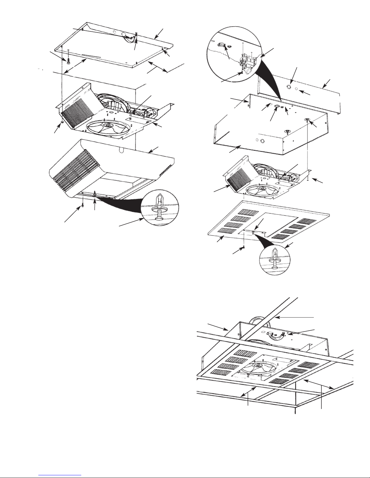
Installation of Surface Mounted Heaters
(See Figures 1 and 2)
1. Determine the desired location of the heater. See Warning
No. 4, page 1 for minimum mounting clearances.
2. Remove Surface Mounted Heater assembly from carton.
Heater assembly includes (1) surface mounting plate,
(1) heater, (1) surface mount enclosure and (1) set of
discharge grilles, Figure 2, page 3.
3. Remove Surface Mount Enclosure from assembly. Remove
four (4) nuts from studs so heater can be removed from surface mounting plate. Do not discard nuts since these will be
used in Step 11 to mount heater back on to surface plate.
4. Remove one of the knockouts and install a cable or conduit
connector.
7/8”(22.2 mm) & 11/8”
(28.6 mm) Nested
Knockout
Screw (2)
Optional
Disconnect
Switch
(CDFDS)
7/8”
(22.2 mm)
Knockout
FFiigguurree 11
5. Install the optional disconnect switch CDFDS (if required) as
shown in Figure 1. Refer to accessory installation manual for
proper wiring.
6. Run the power supply cable through the connector, leaving
about 8” (203 mm) of wire inside the surface mounting plate.
(Power supply cable must be #10 AWG min. rated 90°C minimum. Maximum run length 125' at 208V/5kW.)
1/2”(12.7 mm)
Knockout
Surface
Mounting
Plate
1/2” (12.7 mm) Knockout
Cable or Conduit
Connector
Surface
Mounting Plate
7. Position the surface mounting plate against the ceiling and
secure with bolts or screws (Figure 2). See Warning No. 9,
age 1. Connect the ground wire to the green ground screw
p
on the surface mounting plate.
8. Install optional controls (if required) into the heater section in
accordance with the Instruction Sheet packaged with the
control.
. To wire the heater, thermostat, reduce wattage or convert
9
from single to three-phase voltage, refer to “Field Conversion
for Lower Wattage Rating” or “Conversion for 3ø Installation”
on page 7 and wiring diagrams, Figure 13, page 7.
TO REDUCE THE RISK OF FIRE OR PERMANENT DAMAGE
TO THE HEATER, THERMOSTAT MUST BE WIRED AS
SHOWN IN WIRING DIAGRAM. DO NOT CONNECT THERMOSTAT IN MAIN POWER LINES BECAUSE IT WILL
DEFEAT THE FAN DELAY FUNCTION.
10. Position the heater section over the studs on the surface
mounting plate (Figure 2).
NOTE: The end of the heater section with the terminal block
must be positioned at the end of the surface mounting plate
where the supply wiring enters.
11. Push the heater section onto the studs and securely tighten
four (4) nuts (removed from step 3) on the studs to secure the
heater section to the surface mounting plate (Figure 2).
FAILURE TO INSTALL THE FOUR MOUNTING NUTS COULD
RESULT IN THE HEATER FALLING (SEE FIGURE 2).
NOTE: Insure that the “thumb pin” in each end of the discharge
grille opening is pulled outward to allow the body of the thumb
pins to fit into the holes in the heater section (Figure 2).
12. Position the surface mounting enclosure over heater sec-
tion/surface mounting plate, making sure that the thumb
pins are in the holes in the heater section.
13. With the surface enclosure seated firmly against the heater
section, depress the “thumb pins”. This will cause the
thumb pins to expand and will temporarily hold the surface
enclosure in place.
NOTE: The thumb pins are an aid to help position and hold the
surface mounting enclosure during installation. Additional support (step 14) is required. See Warning.
FAILURE TO INSTALL THE FOUR SCREWS COULD ALLOW
THE SURFACE WRAPPER TO FALL (SEE FIGURE 2).
14. Install and securely tighten four screws (supplied) to secure
the surface mounting enclosure to the heater section
(Figure 2).
15. Install discharge air grilles. (Refer to “Installation of
Discharge Air Grilles”, page 6.)
2
Page 3
Grounding Screw
Screws
or Bolts
(Not Supplied)
Nut (4)
2” (305 mm) Min. 4 kW
1
4” (609 mm) Min. 5 kW
2
Surface Mounting
Plate
Power Supply
Cable
12” (305 mm) Min. 4 kW
24” (609 mm) Min. 5 kW
Thumb Pin
Hole (2)
Heater Section
Surface Mounting Enclosure
Stud (4)
able or
C
onduit
C
onnector
C
Screw (2)
Screw (3)
1/2” (12.7 mm) Knockout
7/8” & 11/8” (22.2 mm
& 28.5 mm) Knockout
Optional
Disconnect
Switch
(CDFDS)
7/8” & 11/8” (22.2 mm &
28.5 mm) Nested Knockout
Side
Panel
1/2” (12.7 mm) Knockout
Grounding
Screw
Stud (4)
Thumb Pin Hole
(2)
Screw (4)
FFiigguurree 22
Insure that “Thumb Pin” is pulled out before positioning
the surface mounting enclosure on the heater section.
Depress “Thumb Pin” after surface enclosure is sealed
firmly against the heater section.
Installation of Recess Mounted Heaters in T-Bar
Ceiling (See Figures 3 and 4)
The recess mounted heater will mount in any standard 2’ x 2’
(609 mm x 609 mm) T-Bar (drop) ceiling. See Warning No. 4 for
minimum mounting clearance and Warning No. 9, page 1.
1. Remove Recess Mounted Heater assembly from carton.
Heater assembly includes (1) recess mounting box, (1)
heater, (1) recess mount face plate and (1) set of discharge
grilles, Figure 3.
2. Remove recess mount box from assembly. Remove four (4)
nuts from studs so heater can be removed from recess
mounting box. Do not discard nuts since these will be used
in Step 9 to mount heater section back on to the recess
mounting box.
3. Remove three screws and the side of the recess mounting
box to allow for easier wiring (Figure 3).
4. Remove one of the knockouts and install a cable or conduit
connector (Figure 3).
5. Install the optional disconnect switch CDFDS (if required as
shown in Figure 3). Refer to accessory instal lation manual
for proper wiring.
6. Install optional controls (if required) into the heater section in
accordance with the Instruction Sheet packaged with the
control.
7. To wire the heater, thermostat, reduce wattage or convert
from single to three-phase voltage, refer to “Field Conversion
for Lower Wattage Rating” or “Conversion for 3ø Installation”
on page 7 and wiring diagrams, Figure 13, page 7.
Recess Mounting Box
Heater Section
Recess Face Plate
Screw (4)
FFiigguurree 33
Heater
Wall
12” (305 mm) Min. 4 kW
24” (609 mm) Min. 5 kW
FFiigguurree 44
3
Thumb Pin Hole (2)
Nut (4)
Thumb
Pin (2)
Insure that “Thumb Pin” is
pulled out before positioning
the face plate on the heater
section. Depress “Thumb Pin”
after face plate is sealed firmly
against the heater section.
T-Bar Grid
Power Supply
Cable
Wall
12” (305 mm) Min. 4 kW
24” (609 mm) Min. 5 kW
Page 4
TO REDUCE THE RISK OF FIRE OR PERMANENT DAMAGE
TO THE HEATER, THERMOSTAT MUST BE WIRED AS
SHOWN IN WIRING DIAGRAM. DO NOT CONNECT THERMOSTAT IN MAIN POWER LINES BECAUSE IT WILL
DEFEAT THE FAN DELAY FUNCTION.
8. Position the heater section over the studs in the recess
ounting box (Figure 3).
m
NOTE: The end of the heater section with the terminal block
ust be posi tioned at the end of the recess mounting box where
m
the supply wiring enters.
9. Push the heater section onto the studs and securely tighten
the four (4) nuts (removed from step 3) on the studs to
secure the heater section to the recess mounting plate
(Figure 3).
16. Connect the ground wire to the green ground screw on the
recess mounting box.
17. After wiring is complete, replace and secure the side of the
recess mount ing box previously removed in Step 3.
18. Install discharge air grilles. Refer to “Installation of
Discharge Air Grilles”, page 6.
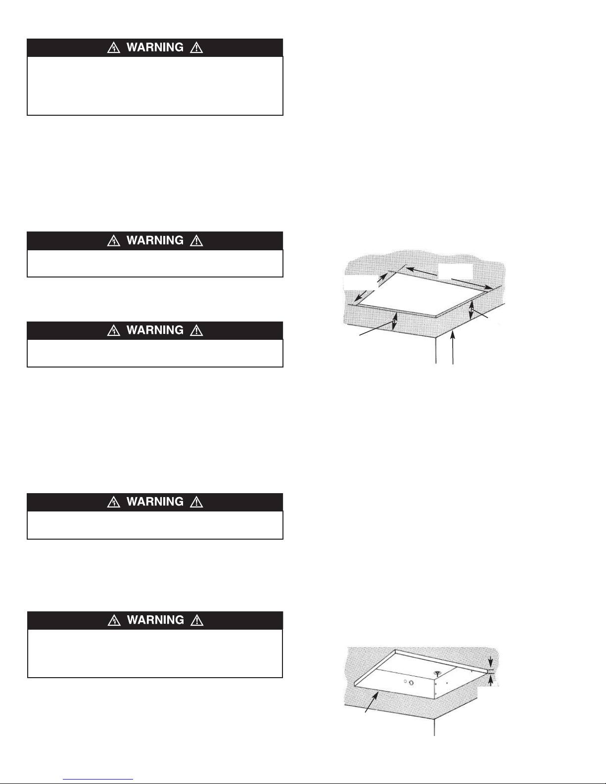
Installation of Recess Mounted Heaters in Permanent
Ceiling (See Figures 5, 6, 7 and 8)
1. Determine the desired location of the heater. See Warning
No. 4 for minimum mounting clearance and Warning No. 9,
page 1.
1
2. Cut a 22
ceiling for the recess mounting box (Figure 5).
. Remove Recess Mounted Heater assembly from carton.
3
Heater assembly includes (1) recess mounting box, (1)
heater, (1) recess mount face plate and (1) set of discharge
grilles.
⁄4” x 221⁄4” (565 mm x 565 mm) mounting hole in the
FAILURE TO INSTALL THE FOUR MOUNTING NUTS COULD
RESULT IN THE HEATER FALLING (SEE FIGURE 3).
NOTE: Insure that the “thumb pin” in each end of the discharge
grille opening is pulled outward to allow the body of the thumb
pins to fit into the holes in the heater section (Figure 3).
FAILURE TO INSTALL THE FOUR SCREWS COULD ALLOW
THE SURFACE WRAPPER TO FALL (SEE FIGURE 3).
10. Position the recess face plate over the heater
section/recess mounting box, making sure that the thumb
pins are in the holes in the heater section.
11. With the recess face plate seated firmly against the heater
section, depress the “thumb pins”. This will cause the
thumb pins to expand and will temporarily hold the recess
face plate in place.
NOTE: The thumb pins are an aid to help position and hold the
recess face plate during installation. Additional support (Step 12)
is required.
FAILURE TO INSTALL THE FOUR SCREWS COULD ALLOW
THE SURFACE WRAPPER TO FALL (SEE FIGURE 3).
12. Install and securely tighten four screws (supplied) to secure
the recess face plate to the heater section (Figure 3).
13. Determine the desired location of the heater.
14. Position the heater in the T-bar grid (Figure 4) and secure
as required.
THE HEATER ENCLOSURE MUST BE SECURELY MOUNTED TO CEILING OR FRAMING CAPABLE OF SUPPORTING
THE HEATER (45 LBS/20.4 KG). FAILURE TO DO SO COULD
ALLOW HEATER TO FALL.
1
2
2
/4”
565 mm)
221/4”
(565 mm)
12” (305 mm) Min. 4 kW
24” (609 mm) Min. 5 kW
Wall
8’ (2438 mm) to Floor Min.
14’ (4267 mm) to Floor Max.
(
12”
(305 mm)
Min. 4 kW
Wall
24”
(609 mm)
Min. 5 kW
FFiigguurree 55
4. Remove recess mount box from assembly. Remove four (4)
nuts from studs so heater can be removed from recess
mounting box. Do not discard nuts since these will be used
in Step 13 to mount heater section back on to the recess
mounting box.
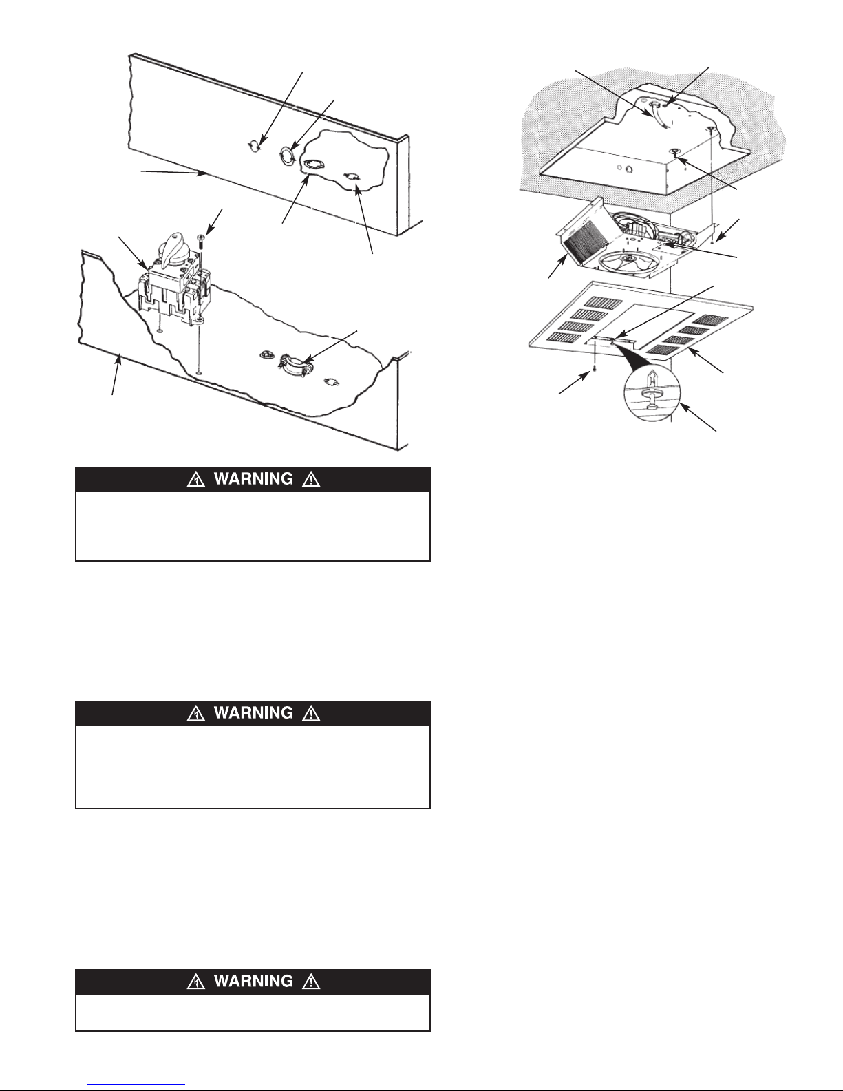
5. Remove one of the knockouts and install a cable or conduit
connector (Figure 7).
6. Install the optional disconnect switch (if required) as shown
in Figure 7.
7. Run the power supply cable through the connector, leaving
about 8” (203 mm) of wire inside the recess mounting box.
(Power supply cable must be #10 AWG min. rated 90°C
minimum.)
8. Place the recess mounting box in the ceiling opening and
align the marks on the sides of the mounting box with the
bottom of the finished ceiling (Figure 6). This will position the
edge of the mounting box 3/8” (9.5 mm) below the ceiling
and will allow the recess face plate to lay flat against the
ceiling.
9. Secure the recess mounting box to the building structure
using a mini mum of four fasteners (not supplied).
15. Run the power supply cable through the connector, leaving
about 8” (203 mm) of wire inside the recess mounting box.
(Power supply cable must be #10 AWG min. rated
90°C minimum.)
FFiigguurree 66
4
Recess Mounting
Box
3/8”
(9.5 mm)
Wall
Wall
Page 5
1/2” (12.2 mm) Knockout
1
7/8” & 1
/8”
(22.2 & 28.5 mm)
Nested Knockout
Recess
Mounting
Box
Optional
Disconnect
Switch (CDFDS)
Recess
Mounting
Box
Screw (2)
7/8” & 11/8”
(22.2 & 28.5 mm)
Nested Knockout
1/2” (12.2 mm)
Knockout
Cable or
Conduit
Connector
FFiigguurree 77
THE HEATER ENCLOSURE MUST BE SECURELY MOUNTED TO CEILING OR FRAMING CAPABLE OF SUPPORTING
THE HEATER (45 LBS/20.4 KG). FAILURE TO DO SO COULD
ALLOW HEATER TO FALL.
10. Install optional controls (if required) into the heater section
in accordance with the Instruction Sheet packaged with the
control.
11. To wire the heater, thermostat, reduce wattage or convert
from single to three-phase voltage, refer to “Field
Conversion for Lower Wattage Rating” or “Conversion for
3ø Installation” on page 7 and wiring diagrams, Figure 13,
page 7.
TO REDUCE THE RISK OF FIRE OR PERMANENT DAMAGE
TO THE HEATER, THERMOSTAT MUST BE WIRED AS
SHOWN IN WIRING DIAGRAM. DO NOT CONNECT THERMOSTAT IN MAIN POWER LINES BECAUSE IT WILL
DEFEAT THE FAN DELAY FUNCTION.
12. Position the heater section over the studs in the recess
mounting box (Figure 8).
Note: The end of the heater section with the terminal block must
be posi tioned at the end of the recess mounting box where the
supply wiring enters.
13. Push the heater section onto the studs and securely tighten
the four (4) nuts (removed from step 4) on the studs to
secure the heater section to the recess mounting box
(Figure 8).
FAILURE TO INSTALL THE FOUR MOUNTING NUTS COULD
RESULT IN THE HEATER FALLING (SEE FIGURE 8).
rounding
G
crew
S
Stud (4)
Nut (4)
Thumb
Pin Hole
Thumb Pin
Recess Face
Plate
FFiigguurree 88
Heater
Section
Screw (4)
Power Supply
Cable
Insure that “Thumb Pin” is pulled out
before positioning the face plate on
the heater section. Depress “Thumb
Pin” after face plate is sealed firmly
against the heater section.
14. Connect the ground wire to the green ground screw on the
recess mounting box.
15. Position the recess face plate over the heater
section/recess mounting box, making sure that the thumb
pins are in the holes in the heater section.
16. With the recess face plate seated firmly against the heater
section, depress the “thumb pins”. This will cause the
thumb pins to expand and will temporarily hold the recess
face plate in place.
Note: The thumb pins are an aid to help position and hold the
recess face plate during installation. Additional support (Step 17)
is required. See Warning, page 2.
17. Install and securely tighten four screws (supplied) to secure
the recess face plate to the heater section (Figure 8).
18. Install discharge air grilles. (Refer to “Installation of
Discharge Air Grilles.”)
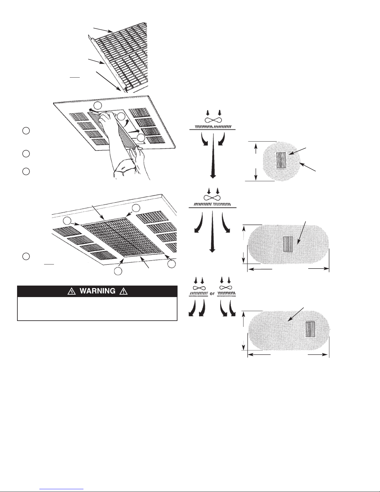
Installation of Discharge Air Grilles
(See Figures 9, 10 and 11)
1. Refer to “Adjustable Discharge Grilles Custom Air Flow
Patterns”, page 6 of this instruction sheet to determine
desired air flow direction.
2. Place the two discharge grilles onto a flat surface in the
desired configura tion with tabs on each end of grilles
upward.
3. Fit the two louver guides over the two discharge grilles as
shown in Figure 9.
4. While holding the assembly together with both hands, fit one
side of assembly into the opening of the enclosure, and slide
this side inward while fitting the opposite side into the enclosure. (See Figure 10.) Slide the assembly into position so
that the bottom portion of each guide locks into the opening.
5
Page 6
9
FFiigguurree 9
Slide grille assembly
1
into opening far enough
to clear louver ends.
2
Push grille assembly up
into opening.
3
Slide grille assembly
into position in opening.
FFiigguurree 1100
Discharge Grille (2)
Louver Guides
Tabs on Discharge
Grilles Must
Upward
Louver Guide
Face
Adjustable Discharge Grilles Custom Air Flow
Patterns (Figure 12)
1. The discharge air pattern is deter mined by the arrangement
of the discharge grilles.
2. Care must be taken when selecting location of heater. Refer
to “Installation of Discharge Air Grilles”, page 5.
Note: The discharge grill area is rectang ular; the discharge
grilles can only be installed parallel to the intake louvers.
DDiisscchhaarrggee AAiirr
1
2
3
1
GGrriillllee AArrrraannggeemmeenntt
NARROW AIR PATTERN for high ceiling applications
(11’ (3352 mm) to 14’ (4267 mm)), concentrates the
heated air to ensure full penetration to the floor level.
8’
(2438 mm)
WIDE AIR PATTERN for standard ceiling applications
(8’ (2438 mm) to 10’ (3048 mm)), disperses the air to
give a gentle, less pronounced pattern while circulating all the air from floor to ceiling.
CCuussttoomm AAiirr
FFllooww PPaatttteerrnn
Heater Discharge
Grilles
Air Pattern on Floor
1
Bottom of each louver
1
guide Must
position in opening.
lock in
1
Louver Guide
FFiigguurree 1111
TO PREVENT THE DISCHARGE GRILLE GUIDES FROM
FALLING, THE GUIDES MUST BE FITTED (LOCKED) IN
POSITION AS SHOWN IN FIGURE 12.
1
FFiigguurree 1122
Air Pattern on Floor
8’
(2438 mm)
24’ (7315 mm)
ASYMMETRICAL AIR PATTERN directs heated air in a
specific direction, allowing the heater to be located
where space allows with the heated air delivered to
where it is required.
Air Pattern on Floor
10’
(3048 mm)
17’ (5181 mm)
6
Page 7
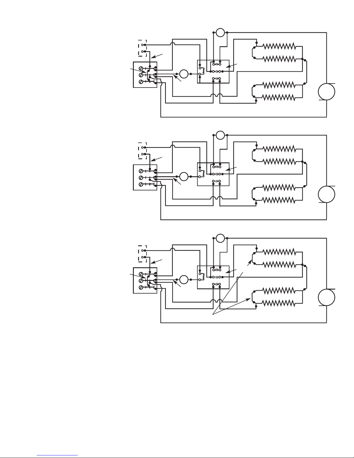
Wiring Diagrams
Standard Wiring Diagram
(Factory Wired)
Optional Field Installed Wall
Thermostat SPST or Internal CDFT
Thermostat Accessory
White
Blue
Power
Block
Blue
Black
White
High
Limit
Black
Black
Blk
Fan Delay
Yellow
L1
L2
L3
Black
Black
Yellow
T1
2
T
T3
Red
Contactor
Red
Element 1
Black
Element 2
Black
Fan
Wiring
Conversion
for 3Ø
Installation
Wiring
Conversion
to Lower
Wattage
(1Ø)
Optional Field Installed Wall
Thermostat SPST or Internal CDFT
Thermostat Accessory
White
Power
Block
Optional Field Installed Wall
Thermostat SPST or Internal CDFT
Thermostat Accessory
White
Blue
Power
Block
Blue
Blue
Black
White
High
Limit
Black
Black
Black
White
High
Limit
Black
Black
Blk
Blk
Fan Delay
Yellow
1
L
L2
3
L
Fan Delay
Yellow
L1
L2
L3
Black
Black
Black
Element 1
Black
Element 2
Element 1
Black
Element 2
Black
Fan
Black
Fan
Yellow
1
T
2
T
3
T
Yellow
T1
T2
T3
Red
Contactor
Red
Black
Red
Contactor
Red
FFiigguurree 1133 –– EElleeccttrriiccaall WWiirriinngg
OPERATION
1. Set the thermostat (internal or remote) to highest setting.
This will energize the heating elements and the fan causing
air to flow from the center of the heater.
2. After the operational check, set the thermostat to obtain the
desired comfort level.
Note: Heater contains a fan delay on shut down.
– The fan energizes immediately when the thermostat turns on
the elements.
– Fan will operate for a short time after the heating elements
are turned off (approx. 1 minute).
Remove One (1) Red Jumper to Obtain 3/4 Nameplate Wattage
Field Conversion for Lower Wattage Rating
(Figure 13)
To convert the heater to a lower watt-age rating, completely
remove one (1) red jumper wire from one heating element for
25% wattage reduction. Completely remove two (2) red jumper
wires for a 50% wattage reduction. Discard the jumper(s). Be
sure the remaining wires are securely connected.
Conversion for 3Ø Installation
Heater is factory wired for connection to 1Ø only. To convert to
3Ø, remove and discard blue jumper wire between L1 & L3.
(Figure 13).
7
Page 8
MAINTENANCE
TO PREVENT ELECTRICAL SHOCK, DISCONNECT ALL
POWER TO HEATER AT MAIN SERVICE PANEL BEFORE
SERVICING.
1. Once each year the heater should be cleaned to remove
ust and foreign material which has collected during the
d
heating season.
2. Turn off all electrical power at the circuit breaker or fuse box
to discon nect the electrical power to heater.
3. Remove dust and other foreign material with a vacuum
leaner nozzle or dust cloth.
c
4. Turn on the main line switch to restore power to the heater.
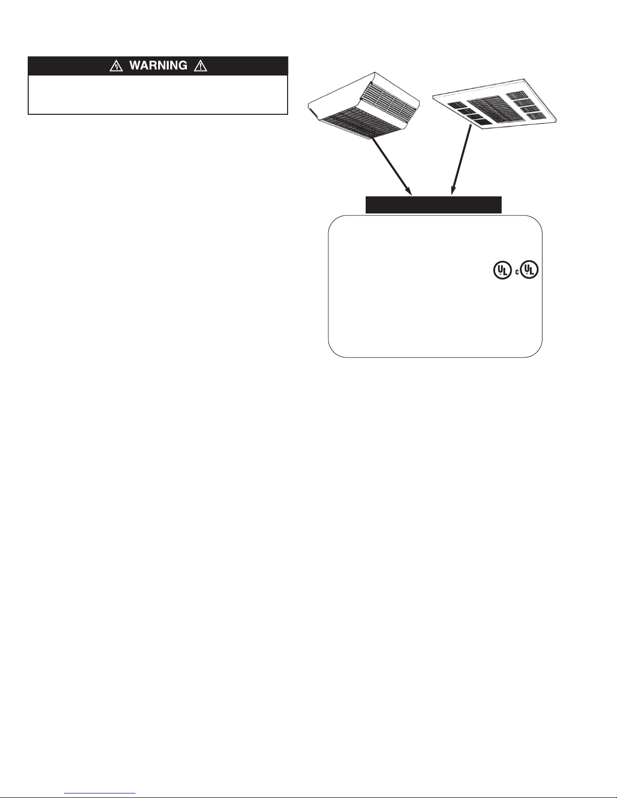
IMPORTANT INFORMATION
NAMEPLATE
MODEL NO. 557 DATE CODE: 1195
CEILING HEATER FAN DECK
BÀTI DU VENTILATEUR, APPAREIL DE PLAFOND
OLTS WATTS AMPS
V
277VAC 5000 18.1
OR SUPPLY CONNECTIONS USE NO. 10AWG
F
OR LARGER WIRES SUITABLE FOR 90°C MIN.
UTILISER UN CÁBLE D´ALIMENTATION D´AU MOINS
NO. 10AWG CONVENANT À UNE TEMPERATURE
´AU MOINS 90°C.
D
774G LISTED
AIR HEATER
Figure 14
8
Page 9

SURFACE
1
7
MOUNTING
ENCLOSURE,
2
6
8
RECESS
4
3
FFiigguurree 1155 –– RReeppaaiirr PPaarrttss IIlllluussttrraattiioonn ffoorr CCeeiilliinngg MMoouunntteedd FFaann FFoorrcceedd HHeeaatteerrss
8
7
MOUNTING
ENCLOSURE,
Repair Parts List for Ceiling Mounted Fan Forced Heaters
Ref. Part Number for Models:
No. Description CDF552SE CDF547SE CDF548SE CDF557SE CDF558SE Qty.
1 Element 302012813 302012803 302012801 302012814 302012812 2
2 Fan Delay 1414-2039-000 1414-2039-000 1414-2039-000 1414-2039-000 1414-2039-000 1
3 Fan Blade 1210-2000-000 1210-2000-000 1210-2000-000 1210-2000-000 1210-2000-000 1
4 Motor 3900-2011-000 3900-2011-001 3900-2011-000 3900-2011-001 3900-2011-000 1
5 High Limit 4520-0011-000 4520-0011-000 4520-0011-000 4520-0011-000 4520-0011-000 1
6 Contactor 5018-0004-102 5018-0004-103 5018-0004-102 5018-0004-103 5018-0004-102 1
7 Outlet Grille 2501-2020-001 2501-2020-001 2501-2020-001 2501-2020-001 2501-2020-001 2
8 Louver Guides 1215-2059-001 1215-2059-001 1215-2059-001 1215-2059-001 1215-2059-001 2
(Surface)
Ref. Part Number for Models:
No. Description CDF552RE CDF547RE CDF548RE CDF557RE CDF558RE Qty.
1 Element 302012813 302012803 302012801 302012814 302012812 2
2 Fan Delay 1414-2039-000 1414-2039-000 1414-2039-000 1414-2039-000 1414-2039-000 1
3 Fan Blade 1210-2000-000 1210-2000-000 1210-2000-000 1210-2000-000 1210-2000-000 1
4 Motor 3900-2011-000 3900-2011-001 3900-2011-000 3900-2011-001 3900-2011-000 1
5 High Limit 4520-0011-000 4520-0011-000 4520-0011-000 4520-0011-000 4520-0011-000 1
6 Contactor 5018-0004-102 5018-0004-103 5018-0004-102 5018-0004-103 5018-0004-102 1
7 Outlet Grille 2501-2020-001 2501-2020-001 2501-2020-001 2501-2020-001 2501-2020-001 2
8 Louver Guides 1215-2059-000 1215-2059-000 1215-2059-000 1215-2059-000 1215-2059-000 2
(Recessed)
9
Page 10

All products manufactured by Marley Engineered Products are warranted against defects in workmanship and materials for one year from date of installation, except
LIMITED WARRANTY
heating elements which are warranted against defects in workmanship and materials for five years from date of installation. This warranty does not apply to damage from
accident, misuse, or alteration; nor where the connected voltage is more than 5% above the nameplate voltage; nor to equipment improperly installed or wired or
maintained in violation of the product’s installation instructions. All claims for warranty work must be accompanied by proof of the date of installation.
The customer shall be responsible for all costs incurred in the removal or reinstallation of products, including labor costs, and shipping costs incurred to return products
to Marley Engineered Products Service Center. Within the limitations of this warranty, inoperative units should be returned to the nearest Marley authorized service center or the Marley Engineered Products Service Center, and we will repair or replace, at our option, at no charge to you with return freight paid by Marley. It is agreed that
such repair or replacement is the exclusive remedy available from Marley Engineered Products.
THE ABOVE WARRANTIES ARE IN LIEU OF ALL OTHER WARRANTIES EXPRESSED OR IMPLIED, AND ALL IMPLIED WARRANTIES OF MERCHANTABILITY AND
FITNESS FOR A PARTICULAR PURPOSE WHICH EXCEED THE AFORESAID EXPRESSED WARRANTIES ARE HEREBY DISCLAIMED AND EXCLUDED FROM
THIS AGREEMENT. MARLEY ENGINEERED PRODUCTS SHALL NOT BE LIABLE FOR CONSEQUENTIAL DAMAGES ARISING WITH RESPECT TO THE
PRODUCT, WHETHER BASED UPON NEGLIGENCE, TORT, STRICT LIABILITY, OR CONTRACT.
Some states do not allow the exclusion or limitation of incidental or consequential damages, so the above exclusion or limitation may not apply to you. This warranty gives
you specific legal rights, and you may also have other rights which vary from state to state.
For the address of your nearest authorized service center, contact Marley Engineered Products in Bennettsville, SC, at 1-800-642-4328. Merchandise returned to the factory must be accompanied by a return authorization and service identification tag, both available from Marley Engineered Products. When requesting return authorization,
include all catalog numbers shown on the products.
HOW TO OBTAIN WARRANTY SERVICE AND
WARRANTY PARTS PLUS GENERAL INFORMATION
1. Warranty Service or Parts 1-800-642-4328
2. Purchase Replacement Parts 1-800-654-3545
3. General Product Information www.marleymep.com
Note: When obtaining service always have the following:
1. Model number of the product
2. Date of manufacture
3. Part number or description
470 Beauty Spot Rd. East
Bennettsville, SC 29512 USA
Part No. 5200-11039-000
ECR 38415
08/09
Page 11

Descripción
Series CDF500
Calentadores de Tiro
Forzado por Ventilador
para Montaje en Cielo Raso
Los calentadores de flujo descendente para montaje en cielo
raso Dayton están diseñados para aplicaciones empotradas o
en superficie. Los calentadores montados en superficie se
extienden sólo 15.2 cm hacia dentro de la habitación. Los calentadores de montaje empotrado se empotran sólo 17.8 cm dentro
del cielo raso. Se monta fácilmente en las cuadrículas de cielo
raso de 609 mm x 609 mm (2 pies x 2 pies).
Instrucciones de instalación, operación y mantenimiento
Especificaciones
Modelo Kw
CDF552SE 5/3.8/2.5 17.2/13.0/8.5 240 1-3 20.8/15.8/10.4 283 (133.5) 45
CDF547SE 4/3/2 13.7/10.2/6.8 277 1 14.5/10.8/7.2 283 (133.5) 51
CDF548SE 4/3/2 13.7/10.2/6.8 208 1-3 19.2/14.4/9.6 283 (133.5) 51
CDF557SE 5/3.8/2.5 17.2/13.0/8.5 277 1 18.1/13.7/9.0 283 (133.5) 45
CDF558SE 5/3.8/2.5 17.2/13.0/8.5 208 1-3 24.0/18.2/12.0 283 (133.5) 45
Modelo Kw
CDF552RE 5/3.8/2.5 17.2/13.0/8.5 240 1-3 20.8/15.8/10.4 283 (133.5) 45
CDF547RE 4/3/2 13.7/10.2/6.8 277 1 14.5/10.8/7.2 283 (133.5) 51
CDF548RE 4/3/2 13.7/10.2/6.8 208 1-3 19.2/14.4/9.6 283 (133.5) 51
CDF557RE 5/3.8/2.5 17.2/13.0/8.5 277 1 18.1/13.7/9.0 283 (133.5) 45
CDF558RE 5/3.8/2.5 17.2/13.0/8.5 208 1-3 24.0/18.2/12.0 283 (133.5) 45
(1) Cableado en la fábrica para el mayor vataje, se puede convertir a vatajes más bajos en el campo.
(2) Cableado en la fábrica para 1Ø, puede convertirse a 3Ø en el campo.
(3) En las unidades de doble fase, se indica el consumo de corriente máximo.
(4) Diferencia de temperatura a la mayor capacidad de vataje.
1
1
BTU/Hr. (000) Voltios Fase
BTU/Hr. (000) Voltios Fase
Montaje en Superficie
Montaje Empotrado
2
2
Amperios
Amperios
3
3
PCM (dm3/s) °F
PCM (dm3/s) °F
4
4
ATENCIÓN: PARA REDUCIR EL PELIGRO DE INCENDIO Y
CHOQUE ELÉCTRICO O DAÑOS PERSONALES, OBSERVE
LO SIGUIENTE:
1. Para evitar el riesgo de choque eléctrico, desconecte toda
la alimentación eléctrica suministrada para el calentador en
el panel principal de servicio antes de intentar hacer
cualquier trabajo de cableado o mantenimiento.
2. Todo el cableado deberá cumplir con los códigos eléctricos
nacionales y loca-les, y el calentador debe conectarse a
tierra como una medida de precaución contra un posible
choque eléctrico.
3. Verifique que el voltaje de alimenta-ción suministrado al
calentador coin-cida con los valores de capacidad impresos
en la placa de identificación del calentador antes de energizarlo.
4. Este calentador está diseñado SOLO para instalación en
cielos rasos. No instale el calentador a menos de
305 mm (12 pulg.) de cualquier pared para los modelos
4kW y 609 mm (24 pulg.) de cualquier pared para los
modelos 5kW.
5. No inserte ni permita que objetos extraños entren en ningu-
CONSERVE ESTAS INSTRUCCIONES
ADVERTENCIA
na abertura de ventilación o escape, ya que esto podría
causar un choque eléctrico, incendio o daños al calentador.
6. Para evitar un posible incendio, no bloquee de ninguna
manera las entradas o salidas de aire. Mantenga los
materiales combustibles, como las cajas de madera,
cortinas, etc. lejos del calentador.
7. Los calentadores tienen en su inte-rior piezas calientes y
productoras de arcos eléctricos (chispas eléctricas). No
utilice el calentador en las áreas donde se utilice o
almacene gasolina, pintura o líquidos inflamables.
8. Este calentador no está aprobado para uso en atmósferas
corrosivas, como por ejemplo, de mar, inver-naderos o
áreas de almacenamiento de productos químicos.
9. La cubierta del calentador debe montarse fijamente en un
cielo raso o entramado que pueda soportar el peso del
calentador (20.4 kg/45 lb.). El calentador se puede caer si
no se cumple con lo anterior.
10. No utilice el calentador si la rejilla de la salida no está instalada. Cuando instale rejillas con guías de rejilla, asegúrese
que las guías queden fijas en posición para que no puedan
deslizarse y soltarse durante el uso de la unidad.
!
Page 12

IMPORTANTE INFORMACION DE SEGURIDAD
EL CALENTADOR SE PUEDE CAER SI NO SE INSTALAN LAS
CUATRO TUERCAS DE MONTAJE PARA FIJAR EL CALENTADOR EN EL BASTIDOR DE MONTAJE (VEA LA FIGURA 2).
LA CUBIERTA PARA SUPERFICIES SE PUEDE CAER SI NO
SE INSTALAN LOS CUATRO TORNILLOS (VEA LA FIGURA 2).
AVISO IMPORTANTE: Este calentador está cableado para que
el ventilador se active sin ningún retardo cuando está energizado
el termostato está pidiendo calor. Cuando el termostato está
y
satisfecho, el ventilador debe seguir funcionando hasta que el
calentador se enfríe y alcance una temperatura no peligrosa. Si
van a utilizarse un termostato externo o controles externos, NO
conecte el calentador de manera que el termostato corte la alimentación eléctrica para el ventilador. El calentador se dañará y
la garantía será anulada. El termostato debe conectarse como se
muestra en el diagrama de cableado (Figura 13, página 17) para
que la unidad funcione correctamente.
AVISO: El cableado de campo deberá ser de tamaño No. 10
AWG como mínimo, con capacidad de 90°C como mínimo.
Máxima longitud de cable de 38 m (125 pies) a 208V/5 kW.
Volumen del compartimiento de cableado: 4130 cm
3
(252 pulg.3).
INSTALACIÓN
Instalación de los Calentadores de Montaje en
Superficie (vea las Figuras 1 y 2)
1. Determine el lugar deseado para el calentador. Consulte la
Advertencia No. 4 en la página 11 para ver los espacios
libres mínimos de montaje.
2. Extraiga de la caja el conjunto del Calentador de Montaje en
Superficie. El conjunto del calentador incluye (1) placa de
montaje en superficie, (1) calentador, (1) cubierta de montaje
en superficie y (1) juego de rejillas de descarga.
3. Extraiga del conjunto la Cubierta de Montaje en Superficie.
Extraiga cuatro (4) tuercas de los pasadores de manera que el
calentador pueda retirarse de la placa de montaje en superficie.
No deseche las tuercas ya que se utilizarán en el Paso 11 para
montar nuevamente el calentador en la placa de superficie.
4. Destape uno de los agujeros ciegos e instale un conector de
cable o conducto.
5. Instale el interruptor de desconexión opcional CDFDS (si es
necesario) como se muestra en la Figura 1. Consulte el
manual de instalación del accesorio para ver cómo se
conecta correctamente éste.
Agujero ciego encajado de
22.2 mm (7/8 pulg.) y
28.6 mm (1
Interrup-tor de
des-conexión
opcional
(CDFDS)
1
/8pulg.)
Tornillo (2)
FFiigguurraa 22
Agujero
ciego de
22.2 mm
(7/8 pulg.)
Agujero ciego de
12.7 mm (1/2 pulg.)
Placa de montaje
en superficie
Agujero ciego de
12.7 mm (1/2 pulg.)
Conector de cable o conducto
Placa de montaje
en superficie
6. Pase el cable de suministro eléctrico a través del conector y
deje aproximadamente 203 mm (8 pulg.) de conductor
entro de la placa de montaje en superficie. (El cable de
d
suministro eléctrico debe ser de tamaño No. 10 AWG como
mínimo, con capacidad de 90°C como mínimo. Máxima
longitud de cable de 38 m [125 pies] a 208V/5 kW.)
7. Coloque la placa de montaje en superficie contra el cielo raso y
fíjela con pernos o tornillos (Figura 2). Consulte la Advertencia
No. 9, en la página 1. Conecte el conductor de tierra al tornillo
verde de conexión a tierra en la placa de montaje en superficie.
8. Instale los controles opcionales (si son necesarios) en la
sección del calentador de acuerdo con la Hoja de
Instrucciones suministrada con el control.
9. Para conectar el calentador, reducir el vataje o convertir de
voltaje monofásico a trifásico, consulte “Conversión en el
campo para una menor capacidad de vatios” o “Conversión
para una instalación trifásica” en la página 17 y en los
diagramas de cableado, Figura 13, página 17.
PARA REDUCIR EL RIESGO DE INCENDIO O DE DAÑO
PERMANENTE AL CALEFACTOR, EL TERMOSTATO DEBE
CABLEARSE COMO SE INDICA EN EL DIAGRAMA DE
CONEXIONADO. NO CONECTE EL TERMOSTATO A LAS
LÍNEAS DE ALIMENTACIÓN PRINCIPAL, PORQUE ESTO
ANULARÁ LA FUNCIÓN DE RETARDO DE VENTILADOR.
10. Coloque la sección del calentador sobre los pasadores de
la placa de montaje en superficie (Figura 2).
AVISO: El extremo de la sección del calentador con el bloque de
terminales debe situarse en el extremo de la placa de montaje
en superficies por donde entra el cable de suministro eléctrico.
11. Presione la sección del calentador sobre los pasadores y
apriete bien las cuatro (4) tuercas (extraídas en el paso 3)
en los pasadores para asegurar la sección del calentador
en la placa de montaje en superficie (Figura 2).
EL CALENTADOR SE PUEDE CAER SI NO SE INSTALAN
LAS CUATRO TUERCAS DE MONTAJE (VEA LA FIGURA 2).
AVISO: Asegúrese que la “espiga de pulgar” en cada extremo
de la aber-tura de la rejilla de descarga no esté totalmente insertada, para permitir que los cuerpos de las espigas de pulgar
quepan en los orificios en la sección del calentador (Figura 2).
12. Coloque la cubierta de montaje en superficie sobre la
sección del calentador y la placa de montaje en superficie,
asegurándose que las espigas de pulgar estén insertadas
en los orificios en la sección del calentador.
13. Con la cubierta para superficies asentada firmemente contra la
sección del calentador, oprima e inserte las “espigas de pulgar”.
Esto causará que se expandan las espigas de pulgar y retendrá
temporalmente en posición la cubierta para superficies.
AVISO: Las espigas de pulgar facilitan la colocación y sujeción
de la cubierta de montaje en superficie durante la instalación.
Será necesario utilizar sujetadores adicionales (paso 14).
Consulte la Advertencia en la página 12.
LA ENVOLTURA PARA SUPERFICIE SE PUEDE CAER SI NO
SE INSTALAN LOS CUATRO TORNILLOS (VEA LA FIGURA 2).
12
Page 13

Tornillos o
pernos (no
suministrados)
Tuerca (4)
Tornillo de conexión
a tierra
05 mm (12 pulg.) mín. 4 kW
3
09 mm (24 pulg.) mín. 5 kW
6
Placa de montaje
en superficie
Cable de suministro
eléctrico
305 mm (12 pulg.) mín. 4 kW
609 mm (24 pulg.) mín. 5 kW
Agujero para espiga
de pulgar (2)
Sección del calentador
Cubierta de montaje en superficie
Pasador (4)
onector
C
e cable
d
conducto
o
Tornillo (2)
Tornillo (3)
Agujero ciego de
12.7 mm (1/2 pulg.)
Agujero ciego de 22.2 mm y
28.5 mm (7/8 pulg. y 1
Tornillo de conexión a tierra
Caja de montaje
empotrado
Interruptor de
desconexión
opcional (CDFDS)
1
/8pulg.)
Agujero ciego encajado
de 22.2 mm y 28.5 mm
(7/8 pulg. y 1
Agujero para
espiga de pulgar (2)
1
/8pulg.)
Agujero ciego de
12.7 mm (1/2 pulg.)
Panel lateral
Pasador
(4)
Tuerca (4)
Tornillo (4)
Agujero para espiga
de pulgar (2)
Asegúrese que la “Espiga de pulgar” no esté totalmente insertada
antes de colocar la cubierta de montaje en superficie sobre la
sección del calentador. Oprima e inserte la “Espiga de pulgar”
después de que la cubierta para superficies esté firmemente
FFiigguurraa 22
sellada contra la sección del calentador.
14. Instale y apriete firmemente cuatro tornillos (suministrados)
para fijar la cubierta de montaje en superficie en la sección
del calentador (Figura 2).
15. Instale las rejillas del aire de des-carga. (Consulte
“Instalación de las rejillas del aire de descarga”, en la
página 16).
Instalacion de los Calentadores de Montaje
Empotrado en Cielos Rasos de Barras T
(vea las Figuras 3 y 4)
El calentador de montaje empotrado puede montarse en
cualquier cielo raso (falso o colgante) de barras T estándar de
609 mm x 609 mm (2 pies x 2 pies).
Consulte la Advertencia No. 4 para los espacios libres mínimos
de montaje y la Advertencia No. 9, en la página 11.
1. Extraiga de la caja el conjunto del Calentador de Montaje
Empotrado. El conjunto del calentador incluye (1) caja de
montaje empotrado, (1) calentador, (1) placa frontal de
montaje empotrado y (1) juego de rejillas de descarga.
2. Extraiga del conjunto la caja de montaje empotrado. Extraiga
cuatro (4) tuercas de los pasadores de manera que el calentador
pueda retirarse de la caja de montaje empotrado. No deseche las
tuercas ya que se utilizarán en el Paso 9 para montar nuevamente
la sección del calentador en la caja de montaje empotrado.
3. Extraiga tres tornillos y retire un lado de la caja de montaje
empotrado para facilitar las conexiones eléctricas (Figura 3).
Sección del calentador
Placa frontal empotrada
Tornillo (4)
FFiigguurraa 33
Calentador
Pared
305 mm (12 pulg.) mín. 4 kW
609 mm (24 pulg.) mín. 5 kW
FFiigguurraa 44
Espiga de
pulgar (2)
Asegúrese que la “Espiga de
pulgar” no esté totalmente
insertada antes de colocar la
placa frontal sobre la sección
del calentador. Oprima e
inserte la “Espiga de pulgar”
después de que la placa frontal
esté firmemente sellada contra
la sección del calentador.
Cuadrícula de barras T
Cable de suministro
eléctrico
Pared
305 mm (12 pulg.) mín. 4 kW
609 mm (24 pulg.) mín. 5 kW
13
Page 14

4. Destape uno de los agujeros ciegos e instale un conector de
cable o conducto (Figura 3).
5. Instale el interruptor de desconexión opcional CDFDS (si es
necesario, según como se muestra en la Figura 3). Consulte
el manual de instalación del accesorio para conectar éste
correctamente.
6. Instale los controles opcionales (si son necesarios) en la
ección del calentador de acuerdo con la Hoja de
s
Instrucciones suministrada con el control.
7. Para conectar el calentador, termóstato, reducir el vataje o
convertir de voltaje monofásico a trifásico, consulte
“Conversión en el campo para una menor capacidad de
vatios” o “Conversión para una instalación trifásica” en la
página 17 y en los diagramas de cableado, Figura 13
PARA REDUCIR EL RIESGO DE INCENDIO O DE DAÑO
PERMANENTE AL CALEFACTOR, EL TERMOSTATO DEBE
CABLEARSE COMO SE INDICA EN EL DIAGRAMA DE
CONEXIONADO. NO CONECTE EL TERMOSTATO A LAS
LÍNEAS DE ALIMENTACIÓN PRINCIPAL, PORQUE ESTO
ANULARÁ LA FUNCIÓN DE RETARDO DE VENTILADOR.
8. Coloque la sección del calentador sobre los pasadores en la
caja de montaje empotrado (Figura 3).
AVISO: El extremo de la sección del calentador con el bloque
de terminales debe situarse en el extremo de la caja de montaje
empotrado por donde entra el cable de suministro eléctrico.
9. Presione la sección del calentador sobre los pasadores y
apriete bien las cuatro (4) tuercas (extraídas en el paso 3)
en los pasadores para asegurar la sección del calentador
en la placa de montaje empotrado (Figura 3).
EL CALENTADOR SE PUEDE CAER SI NO SE INSTALAN
LAS CUATRO TUERCAS DE MONTAJE (VEA LA FIGURA 3).
AVISO: Asegúrese que la “espiga de pulgar” en cada extremo
de la aber-tura de la rejilla de descarga no esté totalmente insertada, para permitir que los cuerpos de las espigas de pulgar
quepan en los orificios en la sección del calentador (Figura 3).
12. Instale y apriete firmemente cuatro tornillos (suministrados)
para fijar la placa frontal empotrada en la sección del calen-
ador (Figura 3).
t
13. Determine el lugar deseado para el calentador.
14. Coloque el calentador en la cuadrícula de barras T (Figura
4) y sujételo según sea necesario.
LA CUBIERTA DEL CALENTADOR DEBE MONTARSE FIJAMENTE EN UN CIELO RASO O ENTRAMADO QUE PUEDA
SOPORTAR EL PESO DEL CALENTADOR (20.4 KG/45 LB.).
EL CALENTADOR SE PUEDE CAER SI NO SE CUMPLE
CON LO ANTERIOR.
15. Pase el cable de suministro eléctrico a través del conector y
deje aproximadamente 203 mm (8 pulg.) de conductor dentro
de la caja de montaje empotrado. (El cable de suministro
eléctrico debe ser de tamaño No. 10 AWG como mínimo, con
capacidad de 90°C como mínimo.)
16. Conecte el conductor de tierra al tornillo verde de conexión
a tierra en la caja de montaje empotrado.
17. Después de hacer las conexiones, reinstale y fije el lado de
la caja de montaje empotrado extraído previamente en el
Paso 3.
18. Instale las rejillas del aire de descarga. Consulte
“Instalación de las rejillas del aire de descarga”, en la
página 16.
Instalacion de los Calentadores de Montaje
Empotrado en Cielos Rasos Permanentes
(vea las Figuras 5, 6, 7 y 8)
1. Determine el lugar deseado para el calentador. Consulte la
Advertencia No. 4 para los espacios libres mínimos de
montaje y la Advertencia No. 9, en la página 1.
1
2. Corte una abertura de montaje de 565 mm x 565 mm (22
pulg. x 221⁄4pulg.) en el cielo raso para la caja de montaje
empotrado (Figura 5).
3. Extraiga de la caja el conjunto del Calentador de Montaje
Empotrado. El conjunto del calentador incluye (1) caja de
montaje empotrado, (1) calentador, (1) placa frontal de montaje
empotrado y (1) juego de rejillas de descarga.
⁄
4
LA ENVOLTURA PARA SUPERFICIE SE PUEDE CAER SI NO
SE INSTALAN LOS CUATRO TORNILLOS (VEA LA FIGURA 3).
10. Coloque la placa frontal empotrada sobre la sección del
calentador y la caja de montaje empotrado, asegurándose
de que las espigas de pulgar estén insertadas en los orificios en la sección del calentador.
11. Con la placa frontal empotrada asentada firmemente contra la
sección del calentador, oprima e inserte las “espigas de pulgar”.
Esto causará que se expandan las espigas de pulgar y retendrá
temporalmente en posición la placa frontal empotrada.
AVISO: Las espigas de pulgar facilitan la colocación y sujeción
de la placa frontal empotrada durante la instalación. Será necesario utilizar sujetadores adicionales (Paso 12).
LA ENVOLTURA PARA SUPERFICIE SE PUEDE CAER SI NO
SE INSTALAN LOS CUATRO TORNILLOS (VEA LA FIGURA 3).
565 mm
(221/4pulg.)
305 mm (12 pulg.) mín. 4 kW
609 mm (24 pulg.) mín. 5 kW
FFiigguurraa 55
Caja de montaje empotrado
FFiigguurraa 55
14
565 mm
(221/4pulg.)
305 mm (12 pulg.) mín. 4 kW
609 mm (24 pulg.) mín. 5 kW
Pared
Mín. de 8 pies (2438 mm) desde el piso
Máx. de 14 pies (4267 mm) desde el piso
Pared
Pared
9.5 mm
(3/8 pulg.)
Pared
Page 15

Agujero ciego de 12.2 mm (1/2 pulg.)
Agujero ciego encajado
Caja de
montaje
empotrado
Interruptor de
desconexión
opcional (CDFDS)
Caja de montaje
empotrado
de 22.2 y 28.5 mm
(7/8 pulg. y 1
Tornillo (2)
Agujero ciego encajado de
22.2 y 28.5 mm
(7/8 pulg. y 11/8pulg.)
1
/8pulg.)
Agujero ciego de
12.2 mm
(1/2 pulg.)
Conector
de cable
o conducto
FFiigguurraa 77
4. Extraiga del conjunto la caja de montaje empotrado. Extraiga
cuatro (4) tuercas de los pasadores de manera que el
calentador pueda retirarse de la caja de montaje empotrado.
No deseche las tuercas ya que se utilizarán en el Paso 13 para
montar nuevamente la sección del calentador en la caja de
montaje empotrado.
5. Destape uno de los agujeros ciegos e instale un conector de
cable o conducto (Figura 7).
6. Instale el interruptor de desconexión opcional (si es
necesario) como se muestra en la Figura 7.
7. Pase el cable de suministro eléctrico a través del conector y
deje aproximadamente 203 mm (8 pulg.) de conductor dentro de la caja de montaje empotrado. (El cable de suministro
eléctrico debe ser de tamaño No. 10 AWG como mínimo,
con capacidad de 90°C como mínimo.)
8. Coloque la caja de montaje empotrado en la abertura en el cielo
raso y alinee las marcas en los lados de la caja de montaje con
la parte inferior del cielo raso acabado (Figura 6). Esto situará el
borde de la caja de montaje a 9.5 mm (3/8 pulg.) por debajo del
cielo raso y permitirá que la placa frontal empotrada descanse
plana sobre el cielo raso.
9. Fije la caja de montaje empotrado en la estructura del edificio usando un mínimo de cuatro sujetadores (no suministrados).
ornillo de
Tuerca (4)
T
onexión a
c
ierra
t
able de
C
uministro
s
léctrico
e
Agujero para
espiga de
pulgar
Placa frontal
empotrada
FFiigguurraa 88
Tornillo (4)
Pasador (4)
Agujero para
espiga de pulgar
Espiga de pulgar
Asegúrese que la “Espiga de
pulgar” no esté totalmente
insertada antes de colocar la
placa frontal sobre la sección
del calentador. Oprima e
inserte la “Espiga de pulgar”
después de que la placa frontal
esté firmemente sellada contra
la sección del calentador.
vatios” o “Conversión para una instalación trifásica” en la
página 17 y en los diagramas de cableado, Figura 13, página 17.
PARA REDUCIR EL RIESGO DE INCENDIO O DE DAÑO
PERMANENTE AL CALEFACTOR, EL TERMOSTATO DEBE
CABLEARSE COMO SE INDICA EN EL DIAGRAMA DE
CONEXIONADO. NO CONECTE EL TERMOSTATO A LAS
LÍNEAS DE ALIMENTACIÓN PRINCIPAL, PORQUE ESTO
ANULARÁ LA FUNCIÓN DE RETARDO DE VENTILADOR.
12. Coloque la sección del calentador sobre los pasadores en
la caja de montaje empotrado (Figura 8).
AVISO: El extremo de la sección del calentador con el bloque
de terminales debe situarse en el extremo de la caja de montaje
empotrado por donde entra el cable de suministro eléctrico.
13. Presione la sección del calentador sobre los pasadores y
apriete bien las cuatro (4) tuercas (extraídas en el paso 4)
en los pasadores para asegurar la sección del calentador
en la caja de montaje empotrado (Figura 9).
EL CALENTADOR SE PUEDE CAER SI NO SE INSTALAN
LAS CUATRO TUERCAS DE MONTAJE (VEA LA FIGURA 8).
LA CUBIERTA DEL CALENTADOR DEBE MONTARSE FIJAMENTE
EN UN CIELO RASO O ENTRAMADO QUE PUEDA SOPORTAR EL
PESO DEL CALENTADOR (20.4 KG/45 LB.). EL CALENTADOR SE
PUEDE CAER SI NO SE CUMPLE CON LO ANTERIOR.
10. Instale los controles opcionales (si son necesarios) en la sección del calentador de acuerdo con la Hoja de Instrucciones
suministrada con el control.
11. Para conectar el calentador, termóstato, reducir el vataje o
convertir de voltaje monofásico a trifásico, consulte
“Conversión en el campo para una menor capacidad de
14. Conecte el conductor de tierra al tornillo verde de conexión
a tierra en la caja de montaje empotrado.
15. Coloque la placa frontal empotrada sobre la sección del
calentador y la caja de montaje empotrado, asegurándose
de que las espigas de pulgar estén insertadas en los orificios en la sección del calentador.
16. Con la placa frontal empotrada asentada firmemente contra
la sección del calentador, oprima e inserte las “espigas de pulgar”. Esto causará que se expandan las espigas de pulgar y
retendrá temporalmente en posición la placa frontal empotrada.
15
Page 16

Rejilla de descarga (2)
Guías de rejilla
Las pestañas de las rejillas
de descarga deben
orientadas hacia arriba
Figura 9
Deslice e inserte el conjunto de la
1
rejilla en la abertura hasta que
pase los extremos de la rejilla.
Empuje el conjunto de la rejilla
2
hacia arriba e insértelo en la
abertura.
Deslice el conjunto de la rejilla a
3
su posición en la abertura.
Figura 10
Guía de rejilla
1
estar
1
Disposición de las rejillas
del aire de descarga
PATRON DE AIRE ESTRECHO: para aplicaciones
de cielos rasos altos (3352 mm [11 pies] a 4267
mm [14 pies]), concentra el aire calentado para
garantizar una penetración total hasta el nivel
del piso.
2438 mm (8
pies)
PATRON DE AIRE AMPLIO: para aplicaciones de
2
3
2438 mm (8
pies)
1
3048 mm (10
pies)
cielos rasos estándar (2438 mm [8 pies] a 3048
mm [10 pies]), dispersa el aire para brindar un
patrón más suave, menos pronunciado, a la vez que
se circula todo el aire desde el piso hasta el cielo
raso.
7315 mm (24 pies)
PATRON DE AIRE ASIMETRICO: dirige el aire
calentado en una cierta dirección, lo cual permite
situar el calentador donde hay suficiente espacio y
el aire calentado es entregado donde se necesita.
Patrón personalizado
de flujo del aire
Rejillas de descarga
del calentador
Patrón de aire en
el piso
Patrón de aire
en el piso
Patrón de aire
en el piso
La parte inferior de cada
1
guía de rejilla debe quedar fija
en posición en la abertura.
1
Figura 11
Guía de rejilla
AVISO: Las espigas de pulgar facilitan la colocación y sujeción
de la placa frontal empotrada durante la instalación. Será necesario utilizar sujetadores adicionales (Paso 17). Consulte la
Advertencia en la página 2.
17. Instale y apriete firmemente cuatro tornillos (suministrados)
para fijar la placa frontal empotrada en la sección del calentador (Figura 8).
18. Instale las rejillas del aire de descarga. (Consulte
“Instalación de las rejillas del aire de descarga”).
Instalacion de las Rejillas del Aire de Descarga
(vea las Figuras 9, 10 y 11)
1. Consulte “Patrones personalizados de flujo del aire de las
rejillas de descarga ajustables”, en la página 16 de esta hoja
de instrucciones para determinar la dirección deseada de
flujo del aire.
2. Coloque las dos rejillas de descarga sobre una superficie
plana usando la configuración con las pestañas en cada
extremo de las rejillas orientadas hacia arriba.
3. Encaje las dos guías de rejilla sobre las dos rejillas de
descarga como se muestra en la Figura 9.
FFiigguurraa 1122
4. Mientras sujeta junto el conjunto con las dos manos, inserte
1
un lado del conjunto en la abertura de la cubierta, y deslice
5181 mm (17 pies)
ese lado hacia adentro mientras encaja el lado opuesto en la
cubierta (vea la Figura 10). Deslice el conjunto en posición
de manera que la porción inferior de cada guía quede firmemente fijada en la abertura.
PARA IMPEDIR QUE LAS GUÍAS DE LAS REJILLAS DE DESCARGA
SE CAIGAN, ÉSTAS DEBEN ENCAJARSE (FIJARSE) EN POSICIÓN
COMO SE MUESTRA EN LA FIGURA 12.
Patrones Personalizados de Flujo del Aire de las
Rejillas de Descarga Ajustables
1. El patrón del aire de descarga es determinado por la disposición de las rejillas de descarga.
2. Se debe tener cuidado al seleccionar la ubicación del calentador. Consulte “Instalación de las rejillas del aire de
descarga”.
AVISO: El área de la rejilla de descarga es rectangular; las rejillas de descarga sólo pueden instalarse paralelas a las rejillas
de admisión.
16
Page 17

iagramas de Cableado
D
Diagrama de cableado estándar
(Cableado en fábrica)
Termóstato unipolar opcional de la
instalación del campo o termóstato
interno 2YU46 auxiliar
Blanco
Azul
Bloque de alimentación
Azul
Negro
Blanco
Límite
alto
Negro
Negro
Retardo del ventilador
L3
Negro
Negro
Negro
Amarillo
Amarillo
T1
L1
L2
2
T
T3
Rojo
Contacto
Rojo
Elemento 1
Negro
Elemento 2
Negro
Ventilador
Conversión del cableado
para instalación trifásica
Conversión del cableado
para un menor vataje
(monofásico)
Termóstato unipolar opcional
de la instalación del campo o
termóstato interno 2YU46 auxiliar
Blanco
Bloque de alimentación
Termóstato unipolar opcional
de la instalación del campo o
termóstato interno 2YU46 auxiliar
Blanco
Azul
Bloque de alimentación
Límite
Azul
Azul
Negro
Blanco
alto
Negro
Negro
Negro
Blanco
Límite
alto
Negro
Negro
Negro
Negro
Retardo del
ventilador
Amarillo
Amarillo
T
1
L
L2
T
3
L
Retardo del
ventilador
Amarillo
Amarillo
T1
L1
L2
T2
L3
Negro
Negro
Negro
Elemento 1
Negro
Elemento 2
Elemento 1
Negro
Elemento 2
Negro
Ventilador
Negro
Ventilador
Rojo
1
2
Contacto
3
T
Rojo
Negro
Rojo
Contacto
T3
Rojo
FFiigguurraa 1133 –– DDiiaaggrraammaa ddee CCaabblleeaaddoo
OPERACIÓN
1. Ajuste el termostato (interior o remoto) a la temperatura más
alta. Esto energizará los elementos de calefacción y el ventilador y causará que el aire fluya desde el centro del calentador.
2. Después de verificar el funcionamiento, ajuste el termostato
para obtener el nivel de comodidad deseado.
AVISO: El calentador tiene un retardo de ventilador para cuando se apaga el calentador.
– El ventilador se energiza inmediatamente cuando el ter-
mostato enciende o activa los elementos.
– El ventilador funcionará durante un corto tiempo después de que se
apagan los elementos de calefacción (aproximadamente 1 minuto).
Retire un (1) puente rojo para obtener 3/4 del vataje indicado en la placa de identificación
Conversion en el Campo para una Menor Capacidad
de Vatios (Figura 13)
Para convertir el calentador para una menor capacidad de
vatios, retire totalmente un (1) conductor rojo de puente de uno
de los elementos de calefacción para reducir el vataje en
un 25%. Retire totalmente dos (2) conductores rojos de puente
para reducir el vataje en un 50%. Deseche el puente o los
puentes. Asegúrese que los conductores restantes estén firmemente conectados.
Conversion para una Instalacion Trifasica
El calentador viene cableado de fábrica sólo para conexión
monofásica. Para convertirlo a trifásico, retire y deseche el conductor azul de puente entre L1 y L3. (Vea la Figura 13).
17
Page 18

MANTENIMIENTO
PARA EVITAR EL RIESGO DE CHOQUE ELÉCTRICO,
DESCONECTE TODA LA ALIMENTACIÓN ELÉCTRICA PARA EL
CALENTADOR EN EL PANEL PRINCIPAL DE SERVICIO ANTES
DE HACER CUALQUIER TRABAJO DE MANTENIMIENTO.
1. Se recomienda limpiar el calentador una vez por año para
eliminar el polvo y todo material extraño que se haya
cumulado durante la temporada de uso de la calefacción.
a
2. Corte el suministro eléctrico en el cortacircuito o la caja de
usibles para desconectar la alimentación eléctrica para el
f
calentador.
3. Limpie el polvo y todo otro material extraño con la boquilla
de una aspiradora o un trapo para limpiar polvo.
4. Vuelva a conectar el suministro eléctrico en el interruptor
principal de la línea de suministro para restablecer la alimentación eléctrica para el calentador.
INFORMACIÓN IMPORTANTE
PLACA DE IDENTIFICACION
FFiigguurraa 1144
ODELO NO.
M
PLATAFORMA DE VENTILADOR DE CALENTADOR
DE CIELO RASO
VOLTIOS VATIOS AMPERIOS
77V CA 5000 18.1
2
PARA LAS CONEXIONES DE SUMINISTRO
ELECTRICO UTILICE CONDUCTORES NO.
0 AWG O DE MAYOR CALIBRE ADECUADOS
1
PARA NO MENOS DE 90°C.
557 C
ODIGO DE FECHA:
1195
CALENTADOR DE
AIRE CON CLASIFI-
CACION 774G
18
Page 19

1
7
CUBIERTA DE MONTAJE
EN SUPERFICIE,
2
6
4
5
Figura 17 – Ilustración de las Partes de Reparación para los Calentadores de Tiro Forzado por Ventilador para Montaje en Cielo Raso y
Juego de Junta de Ajuste Auxiliar 2YU47
3
8
CUBIERTA DE MONTAJE
8
7
EMPOTRADO,
Lista de Partes de Reparación para los Calentadores de Tiro Forzado por Ventilador para
Montaje en Cielo Raso
No. de Número de Parte para Modelos:
Ref. Descripción CDF552SE CDF547SE CDF548SE CDF557SE CDF558SE Cant.
1 Elemento 302012813 302012803 302012801 302012814 302012812 2
2 Retardo del 1414-2039-000 1414-2039-000 1414-2039-000 1414-2039-000 1414-2039-000 1
3 Aspas del 1210-2000-000 1210-2000-000 1210-2000-000 1210-2000-000 1210-2000-000 1
4 Motor 3900-2011-000 3900-2011-001 3900-2011-000 3900-2011-001 3900-2011-000 1
5 Límite alto 4520-0011-000 4520-0011-000 4520-0011-000 4520-0011-000 4520-0011-000 1
6 Contratista 5018-0004-102 5018-0004-103 5018-0004-102 5018-0004-103 5018-0004-102 1
7 Rejilla de salida 2501-2020-001 2501-2020-001 2501-2020-001 2501-2020-001 2501-2020-001 2
8 Guías de rejilla 1215-2059-001 1215-2059-001 1215-2059-001 1215-2059-001 1215-2059-001 2
No. de Número de Parte para Modelos:
Ref. Descripción CDF552RE CDF547RE CDF548RE CDF557RE CDF558RE Cant.
1 Elemento 302012813 302012803 302012801 302012814 302012812 2
2 Retardo del 1414-2039-000 1414-2039-000 1414-2039-000 1414-2039-000 1414-2039-000 1
3 Aspas del 1210-2000-000 1210-2000-000 1210-2000-000 1210-2000-000 1210-2000-000 1
4 Motor 3900-2011-000 3900-2011-001 3900-2011-000 3900-2011-001 3900-2011-000 1
5 Límite alto 4520-0011-000 4520-0011-000 4520-0011-000 4520-0011-000 4520-0011-000 1
6 Contratista 5018-0004-102 5018-0004-103 5018-0004-102 5018-0004-103 5018-0004-102 1
7 Rejilla de salida 2501-2020-001 2501-2020-001 2501-2020-001 2501-2020-001 2501-2020-001 2
8 Guías de rejilla 1215-2059-000 1215-2059-000 1215-2059-000 1215-2059-000 1215-2059-000 2
ventilador
ventilador
(En superficie)
ventilador
ventilador
(Empotradas)
19
Page 20

Todos los productos fabricados por Marley Engineered Products están garantizados contra defectos de fabricación y de materiales por 1 año desde la fecha de
GARANTÍA LIMITADA
instalación. Esta garantía no se aplica a daños debidos a accidente, mal uso o alteración, ni a los casos en que la tensión eléctrica conectada supere a la tensión nominal -indicada en la placa de características- en más de 5 %, ni a equipos que hayan sido instalados o cableados incorrectamente, o mantenidos en
forma que no cumpla lo indicado en las instrucciones de instalación del producto. Todo reclamo por trabajos en garantía debe acompañarse con una prueba de
la fecha de instalación.
El cliente será responsable de todos los costos incurridos en el retiro o reinstalación de productos, incluyendo los costos de mano de obra y los costos de envío
incurridos para regresar productos a un Centro de Servicio de Marley Engineered Products. Dentro de las limitaciones de esta garantía, las unidades que no
funcionan deben regresarse al centro de servicio autorizado Marley más cercano, o al Centro de Servicio de Marley Engineered Products, y nosotros lo
repararemos o reemplazaremos, a nuestra opción, sin cargo para usted, con el flete de retorno pagado por Marley. Se acuerda que tal reparación o reemplazo
es el único recurso que Marley Engineered Products pone a su disposición.
LAS GARANTÍAS EXPUESTAS MÁS ARRIBA TOMAN EL LUGAR DE TODA OTRA GARANTÍA, EXPRESA O IMPLÍCITA, Y POR LA PRESENTE SE
DECLINA Y EXCLUYE DE ESTE ACUERDO TODA GARANTÍA IMPLÍCITA DE COMERCIABILIDAD Y ADECUACIÓN A UN PROPÓSITO PARTICULAR QUE
EXCEDA LAS GARANTÍAS EXPRESAS ANTEDICHAS. MARLEY ENGINEERED PRODUCTS NO SE HARÁ RESPONSABLE POR DAÑOS CONSIGUIENTES
QUE SE PRODUZCAN CON RESPECTO AL PRODUCTO, EN BASE YA SEA A NEGLIGENCIA, AGRAVIO, RESPONSABILIDAD ESTRICTA, O CONTRATO.
Algunos estados o jurisdicciones no permiten la exclusión o limitación de daños incidentales o consiguientes, de modo que la exclusión o limitación expresada
más arriba puede no aplicarse a su caso. Esta garantía le da derechos legales específicos, y usted puede tener también otros derechos, que varían de un estado o jurisdicción a otro.
Para obtener la dirección de su centro de servicio autorizado más cercano comuníquese con Marley Engineered Products en Bennettsville, SC, Estados Unidos,
llamando al 1-800-642-4328. Toda mercadería regresada a la fábrica debe ser acompañada por una autorización de retorno y una etiqueta de identificación de
servicio, disponibles ambas en Marley Engineered Products. Cuando solicite la autorización de retorno, incluya todos los números de catálogo mostrados en los
productos.
CÓMO OBTENER SERVICIO EN GARANTÍA, PIEZAS DE
REPUESTO E INFORMACIÓN GENERAL
1. Servicio o repuestos en garantía 1-800-642-4328
2. Compra de repuestos 1-800-654-3545
3. Información general sobre productos www.marleymep.com
Nota: cuando solicite servicio, siempre dé la información que sigue:
1. Número de modelo del producto
2. Fecha de fabricación
3. Número de parte o descripción
470 Beauty Spot Rd. East
Bennettsville, SC 29512 USA
Número de parte 5200-11039-000
ECR 38415
08/09
Page 21

Description
Séries CDF500
Radiateurs à air pulsé
installés au plafond
Les radiateurs à circulation descendante installés au plafond sont
conçus pour des applications encastrées ou en applique. Les radiateurs en applique dépassent de seulement 15,2 cm dans la pièce.
Les radiateurs encastrés s'enfoncent sur seulement 17,8 cm dans
le plafond. S'installe aisément dans des panneaux de 2 pi x 2 pi
des plafonds suspendus.
Instructions d'installation, d’utilisation et d'entretien
Spécifications
Modèle Kw
CDF552SE 5/3,8/2,5 17,2/13,0/8,5 240 1-3 20,8/15,8/10,4 283 (133,5) 45
CDF547SE 4/3/2 13,7/10,2/6,8 277 1 14,5/10,8/7,2 283 (133,5) 51
CDF548SE 4/3/2 13,7/10,2/6,8 208 1-3 19,2/14,4/9,6 283 (133,5) 51
CDF557SE 5/3,8/2,5 17,2/13,0/8,5 277 1 18,1/13,7/9,0 283 (133,5) 45
CDF558SE 5/3,8/2,5 17,2/13,0/8,5 208 1-3 24,0/18,2/12,0 283 (133,5) 45
Modèle Kw
CDF552RE 5/3,8/2,5 17,2/13,0/8,5 240 1-3 20,8/15,8/10,4 283 (133,5) 45
CDF547RE 4/3/2 13,7/10,2/6,8 277 1 14,5/10,8/7,2 283 (133,5) 51
CDF548RE 4/3/2 13,7/10,2/6,8 208 1-3 19,2/14,4/9,6 283 (133,5) 51
CDF557RE 5/3,8/2,5 17,2/13,0/8,5 277 1 18,1/13,7/9,0 283 (133,5) 45
CDF558RE 5/3,8/2,5 17,2/13,0/8,5 208 1-3 24,0/18,2/12,0 283 (133,5) 45
(1) Câblé en usine pour la plus grande puissance, convertible sur site à des puissances plus basses.
(2) Câblé à l'usine 1 Ø, peut être converti sur le site à 3 Ø.
(3) Sur les appareils à deux phases, l'appel maximum de l'ampérage figure dans la liste.
(4) Différence de température à la puissance la plus élevée.
1
1
BTU/h (000) Volts Phase
BTU/h (000) Volts Phase
En applique
Encastré
2
2
Ampères
Ampères
3
3
PCM (dm3/s) °F
PCM (dm3/s) °F
4
4
AVERTISSEMENT
ATTENTION – POUR RÉDUIRE LES RISQUES D’INCENDIE,
D’ÉLECTROCUTION ET D’AUTRES BLESSURES
OBSERVEZ LES CONSIGNES SUIVANTES :
1. Afin d'éviter un risque de décharge électrique, couper l'alimentation du radiateur au niveau du panneau de service
principal avant d'effectuer le câblage ou l'entretien.
2. Tout le câblage doit être conforme au Code national de
l'électricité et aux codes locaux; et le radiateur doit être mis
à la terre en guise de précaution contre les décharges électriques.
3. Avant de mettre sous tension, vérifier que la tension d'alimentation correspond aux valeurs nominales imprimées sur
la plaque signalétique.
4. Ce radiateur est destiné à être monté au plafond SEULEMENT. Ne pas installer le radiateur à moins de 305 mm (12
po) d'un mur quelconque pour les modèles 4kW et à moins
de 609 mm (24 po) pour les modèles 5kW.
5. Ne pas insérer ou laisser des corps étrangers pénétrer dans
toute ouverture de ventilation ou de sortie, car il pourrait en
résulter une décharge électrique, un incendie ou des dom-
CONSERVER CES INSTRUCTIONS
!
mages au radiateur.
6. Afin d'éviter la possibilité d'un incendie, ne pas bloquer les
entrées ou les sorties d'air d'une quelconque manière.
Garder les matériaux combustibles, comme les caisses, les
draperies, etc., loin du radiateur.
7. Un radiateur comprend des pièces chaudes et qui produisent un arc électrique ou forment des étincelles à l'intérieur. Ne pas utiliser dans des endroits où sont utilisés ou
entreposés de l'essence, de la peinture ou des liquides
inflammables.
8. Ce radiateur n'est pas approuvé pour une utilisation dans
des atmosphères corrosives, comme des zones marines,
des serres ou d'entreposage de produits chimiques.
9. L'enveloppe du radiateur doit être installée de façon sécuritaire au plafond ou dans un cadre pouvant supporter le radiateur (20,4 kg / 45 lb). Sinon le radiateur pourrait tomber.
10. Ne pas utiliser le radiateur sans avoir installé ses grilles de
sortie. Lors de l'installation des grilles avec guides de lame,
s'assurer que les guides tombent en position afin qu'ils ne
glissent pas durant l'utilisation.
Page 22

INFORMATIONS IMPORTANTES SUR LA SÉCURITÉ
NÉGLIGER D'INSTALLER LES QUATRE ÉCROUS DE MONTAGE POUR FIXER SOLIDEMENT LE CADRE DE MONTAGE POURRAIT ENTRAÎNER LA CHUTE DU RADIATEUR
(VOIR LA FIGURE 2).
NÉGLIGER D'INSTALLER LES QUATRE VIS POURRAIT
ENTRAÎNER LA CHUTE DE L'ENVE-LOPPE D'APPLIQUE
VOIR LA FIGURE 2).
(
AVIS IMPORTANT : Ce radiateur est câblé pour que le ventilateur s'active sans délai lorsqu'il est excité alors que le thermostat fait un appel de chaleur. Lorsque le thermostat est satisfait,
le ventilateur doit continuer à fonctionner jusqu'à ce que le radiateur ait refroidi à une température sécuritaire. Si un thermostat
externe ou des commandes sont utilisées, NE PAS câbler le
radia-teur pour que le thermostat coupe l'alimentation au ventilateur. Le radiateur sera endommagé et la garantie annulée. Pour
fonctionner correctement, le thermostat doit être raccordé
comme il est illustré sur le schéma de câblage (Figure 13,
page 27).
o
REMARQUE : Le câblage sur le site doit être n
10 AWG au
minimum avec caractéristique nominale minimale de 90 °C.
Longueur d'acheminement maximale de 38 m (125 pi) à 208 V/
5 kW. Volume du compartiment de câblage - 4130 cm
3
(252
po3).
INSTALLATION
Installation des radiateurs en applique
(voir les Figures 1 et 2)
1. Déterminer l'emplacement du radiateur. Voir l'avertissement
o
4, page 21, pour connaître les dégagements minima.
n
2. Retirer le radiateur en applique de l’emballage de carton. Le
radiateur inclut (1) plaque d’applique, (1) radiateur, (1)
enveloppe d’applique et (1) jeu de grilles.
3. Retirer l’enveloppe d’applique de l’ensemble. Enlever les
quatre (4) écrous des montants afin de pouvoir enlever le
radiateur de la plaque de montage en saillie. Ne pas jeter
les écrous car ils seront utilisés à l'étape 11 pour réinstaller
le radiateur sur la plaque en saillie.
4. Enlever une des alvéoles et installer un connecteur de câble
ou de conduit.
5. Installer le disjoncteur en option CDFDS (si exigé) comme
l'illustre la Figure 1. Consulter le manuel d'installation des
accessoires pour câbler correctement.
Alvéole défonçable emboîtée 22,2
mm et 28,6 mm
(7/8 po et 1
Alvéole défonçable
22,2 mm (7/8 po)
Disjoncteur en
option (CDFDS
1
/8po)
Vis (2)
FFiigguurree 11
Alvéole défonçable 12,7 mm (1/2 po)
Fil ou connecteur de conduit
Alvéole défonçable
12,7 mm (1/2 po)
Plaque de
montage
en applique
Plaque de montage
en applique
6. Acheminer le câble d'alimentation à travers le connecteur en
laissant environ 203 mm (8 po) à l'intérieur de la plaque
'applique. (Le câble d'alimentation doit être de no 10 AWG
d
au minimum avec caractéris-tique nominale minimale de 90
°C. Longueur d'acheminement maxi-male de 38 m (125 pi) à
208 V/5 kW.)
7. Placer la plaque d'applique contre le plafond et la fixer
solidement avec des boulons ou des vis (Figure 2). Voir
l'avertissement no 9, à la page 21. Connecter le fil de terre à
la vis de terre verte sur la plaque d'applique.
8. Installer les commandes en option (si requises) sur la partie
radiateur en suivant la feuille d'instructions emballée avec la
commande.
9. Pour câbler le radiateur, réduire la puissance ou convertir
d'une tension monophasée à une tension tri-phasée, consulter « Conversion sur le site à une puissance plus basse » ou
« Conversion pour une installation 3 ø » à la page 27 et le
schéma de câblage, Figure 13, page 27.
AFIN DE RÉDUIRE LES RISQUES D’INCENDIE ET D’ÉVITER
D’ENDOMMAGER LE RADIATEUR, LE THERMOSTAT DOIT
ÊTRE BRANCHÉ COMME INDIQUÉ SUR LE SCHÉMA DE
CÂBLAGE. NE PAS BRANCHER LE THERMOSTAT SUR LE
SECTEUR CAR CELA NUIRAIT AU FONCTION-NEMENT DU
RETARD DE MISE EN MARCHE DU VENTILATEUR.
10. Placer la partie radiateur par-dessus les goujons sur la
plaque d'applique (Figure 2).
REMARQUE : L'extrémité de la partie radiateur qui comporte un
bornier doit être placée à l'extrémité de la plaque d'applique, à
l'entrée du câblage d'alimentation.
11. Pousser la section radiateur sur les montants et fixer solidement
les quatre (4) écrous (enlevés à l’étape 3) sur les montants afin
de fixer solidement la section radiateur sur la plaque de montage
en saillie (Figure 2).
NÉGLIGER D'INSTALLER LES QUATRE ÉCROUS DE MONTAGE POURRAIT ENTRAÎNER LA CHUTE DU RADIATEUR
(VOIR LA FIGURE 2).
REMARQUE : S'assurer que la « tige poussoir » à chaque
extrémité de l'ouverture de la grille d'évacuation est tirée vers
l'extérieur pour laisser le corps des tiges poussoir s'ajuster dans
les trous de la partie radiateur (Figure 2).
12. Placer l'enveloppe d'applique par-dessus partie
radiateur/plaque d'applique, en s'assurant que les tiges
poussoir sont dans les trous de la partie radiateur.
13. Alors que l'enveloppe d'applique est fermement logée con-
tre la partie radiateur, appuyer sur les « tiges poussoir ».
Ceci déploie les tiges poussoir et maintient temporairement
l'enveloppe d'applique en place.
REMARQUE : Les tiges poussoir aident à placer et maintenir
l'enveloppe d'applique pendant l'installation. Un support supplémentaire est requis (étape 14). Voir l'avertissement.
NÉGLIGER D'INSTALLER LES QUATRE VIS POURRAIT
ENTRAÎNER LA CHUTE DE L'ENVE-LOPPE D'APPLIQUE
(VOIR LA FIGURE 2).
22
Page 23

Vis de mise à la terre
Vis et boulons
(non fournis)
05 mm (12 po) min. 4 kW
3
09 mm (24 po) min. 5 kW
6
Plaque de montage en applique
Câble d'alimentation
électrique
305 mm (12 po) min. 4 kW
609 mm (24 po) min. 5 kW
Goujon (4)
il ou connecteur
F
e conduit
d
Vis (2)
Disjoncteur en
option (CDFDS)
Panneau
latéral
Alvéole défonçable
22,2 mm et 28,5 mm
(7/8 po et 1
1
/8po)
Alvéole défonçable
12,7 mm (1/2 po)
Trou de tige
poussoir (2)
Écrou (4)
Vis (4)
FFiigguurree 22
Trou de tige poussoir (2)
S'assurer que la « tige poussoir » est tirée avant de placer
l'enveloppe d'applique sur la partie radiateur. Appuyer sur
la « tige poussoir » une fois l'enveloppe d'applique installée de façon étanche contre la partie radiateur.
Partie radiateur
Enveloppe d'applique
14. Installer et serrer fermement les quatre vis (fournies) pour
fixer solidement l'enveloppe d'applique à la partie radiateur
(Figure 2).
15. Installer les grilles d'évacuation d'air. (Consulter la section «
Installation des grilles d'évacuation d'air » à la page 26.)
Installation de radiateurs encastrés dans des
plafonds « T » (voir les Figures 4 et 5, pages 4 et 5)
Le radiateur encastré peut être installé dans tout plafond suspendu « T » de 609 mm x 609 mm (2 pi x 2 pi). Voir l'avertisse-
o
ment n
ment no9 á la page 21.
1. Retirer le radiateur en applique de l’emballage de carton. Le
2. Séparer la boîte d’encastrement de l’ensemble. Enlever les
3. Enlever les trois vis et le côté de la boîte d'encastrement pour
4. Enlever une des alvéoles et installer un connecteur de câble ou
5. Installer le disjoncteur en option CDFDS (si exigé, comme
4 pour connaître le dégagement minimal et l'avertisse-
radiateur inclut (1) boîte d'encastrement, (1) radiateur, (1)
plaque d’encastrement et (1) jeu de grilles.
quatre (4) écrous des montants afin de pouvoir enlever le
radiateur de la boîte de montage encastrée. Ne pas jeter les
écrous car ils seront utilisés à l'étape 9 pour réinstaller le
radiateur sur la boîte de montage encastrée.
faciliter le câblage (Figure 3).
de conduit (Figure 3).
l'illustre la Figure 3). Consulter le manuel d'installation des
accessoires pour câbler correctement.
Vis (3)
Alvéole défonçable 12,7 mm (1/2 po)
Alvéole défonçable 22,2 mm et
28,5 mm (7/8 po et 11/8po)
Vis de mise à la terre
Boîte d'encastrement
Partie radiateur
Tige poussoir
(2)
Plaque d'encastrement
Vis (4)
FFiigguurree 33
Radiateur
Mur
305 mm (12 po) min. 4 kW
609 mm (24 po) min. 5 kW
FFiigguurree 44
Goujon
(4)
Trou de tige poussoir (2)
Écrou (4)
S'assurer que la « tige poussoir » est tirée avant de placer
la plaque d'encastrement sur
la partie radiateur. Appuyer
sur la « tige poussoir » une
fois la plaque d'encastrement
installée de façon étanche
contre la partie radiateur.
Grille de barres en T
Câble d'alimentation
électrique
Mur
305 mm (12 po) min. 4 kW
609 mm (24 po) min. 5 kW
6. Installer les commandes en option (si requises) sur la partie
radiateur en suivant la feuille d'instructions emballée avec la
commande.
23
Page 24

7. Pour câbler le radiateur, thermostat réduire la puissance ou convertir d'une tension monophasée à une tension triphasée, con-
ulter « Conversion sur le site à une puissance plus basse » ou
s
« Conversion pour une installation 3 ø » à la page 27 et le
schéma de câblage, Figure 13, page 27.
L'ENVELOPPE DU RADIATEUR DOIT ÊTRE INSTALLÉE DE
FAÇON SÉCURITAIRE AU PLAFOND OU DANS UN CADRE
POUVANT SUPPORTER LE RADIATEUR (20,4 KG / 45 LB).
SINON LE RADIATEUR POURRAIT TOMBER.
AFIN DE RÉDUIRE LES RISQUES D’INCENDIE ET D’ÉVITER
D’ENDOMMAGER LE RADIATEUR, LE THERMOSTAT DOIT
ÊTRE BRANCHÉ COMME INDIQUÉ SUR LE SCHÉMA DE
CÂBLAGE. NE PAS BRANCHER LE THERMOSTAT SUR LE
ECTEUR CAR CELA NUIRAIT AU FONCTION-NEMENT DU
S
RETARD DE MISE EN MARCHE DU VENTILATEUR.
8. Placer la partie radiateur par-dessus les goujons dans la
boîte d'encas-trement (Figure 3).
REMARQUE : L'extrémité de la partie radiateur qui comporte un
bornier doit être placée à l'extrémité de la boîte d'encastrement,
à l'entrée du câblage d'alimentation.
9. Pousser la section radiateur sur les montants et fixer solidement
les quatre (4) écrous (enlevés à l’étape 3) sur les montants afin
de fixer solidement la section radiateur sur la plaque de montage encastrée (Figure 3).
NÉGLIGER D'INSTALLER LES QUATRE ÉCROUS DE MONTAGE POURRAIT ENTRAÎNER LA CHUTE DU RADIATEUR
(VOIR LA FIGURE 3).
REMARQUE : S'assurer que la « tige poussoir » à chaque
extrémité de l'ouverture de la grille d'évacuation est tirée vers
l'extérieur pour laisser le corps des tiges poussoir s'ajuster dans
les trous de la partie radiateur (Figure 3).
15. Acheminer le câble d'alimentation à travers le connecteur
en laissant environ 203 mm (8 po) à l'intérieur de la boîte
'encastrement. (Le câble d'alimentation doit être de n
d
o
0
1
AWG au minimum avec caractéristique nominale minimale
de 90 °C.)
16. Connecter le fil de terre à la vis de terre verte sur la boîte
d'encastrement.
17. Une fois le câblage complété, remettre en place et fixer
solidement le côté de la boîte d'encastrement enlevé à l'étape 3.
18. Installer les grilles d'évacuation d'air. Consulter la section
« Installation des grilles d'évacuation d'air » à la page 26.
Installation de radiateurs encastrés dans des plafonds permanents (voir les Figures 5, 6, 7 et 8)
1. Déterminer l'emplacement du radiateur. Voir l'avertissement
no 4 pour connaître le dégagement minimal et l'avertissement no 9 à la page 21.
1
2. Découper une ouverture de 565 mm x 565 mm (22
221⁄4po) dans le plafond pour installer la boîte
d'encastrement (Figure 5).
565 mm
565 mm
(221/4po)
(221/4po)
⁄4po x
NÉGLIGER D'INSTALLER LES QUATRE VIS POURRAIT
ENTRAÎNER LA CHUTE DE L'ENVE-LOPPE D'APPLIQUE
(VOIR LA FIGURE 3).
10. Placer la plaque d'encastrement par-dessus la partie radiateur/boîte d'encastrement, en s'assurant que les tiges poussoir sont dans les trous de la partie radiateur.
11. Alors que la plaque d'encastrement est fermement logée
contre la partie radiateur, appuyer sur les « tiges
poussoir ». Ceci déploie les tiges poussoir et maintient temporairement la plaque d'encastrement en position.
REMARQUE : Les tiges poussoir aident à placer et maintenir la
plaque d'encastrement pendant l'installation. Un support supplémentaire est requis (étape 12).
NÉGLIGER D'INSTALLER LES QUATRE VIS POURRAIT
ENTRAÎNER LA CHUTE DE L'ENVE-LOPPE D'APPLIQUE
(VOIR LA FIGURE 3).
12. Installer et serrer fermement les quatre vis (fournies) pour
fixer solidement la plaque d'encastrement à la partie
radiateur (Figure 3).
13. Déterminer l'emplacement du radiateur.
14. Placer le radiateur dans la grille des barres en T (Figure 4)
et fixer solidement comme il convient.
Mur
305 mm (12 po)
min. 4 kW
609 mm (24 po)
min. 5 kW
FFiigguurree 55
305 mm (12 po) min.
4 kW
609 mm (24 po) min.
5 kW
Mín. de 8 pi (2 438 mm) du plancher
Máx. de 14 pi (4 267 mm) du plancher
Mur
3. Retirer le radiateur en applique de l’emballage de carton.
Le radiateur inclut (1) boîte d'encastrement, (1) radiateur,
(1) plaque d’encastrement et (1) jeu de grilles.
4. Séparer la boîte d’encastrement de l’ensemble. Enlever les
quatre (4) écrous des montants afin de pouvoir enlever le
radiateur de la boîte de montage encastrée. Ne pas jeter les
écrous car ils seront utilisés à l'étape 13 pour réinstaller le
radiateur sur la boîte de montage encastrée.
5. Enlever une des alvéoles et installer un connecteur de câble
ou de conduit (Figure 7).
6. Installer le disjoncteur en option (si exigé) comme l'illustre la
Figure 7.
9,5 mm
(3/8 po)
Boîte d'encastrement
Mur
Mur
FFiigguurree 66
24
Page 25

7. Acheminer le câble d'alimentation à travers le connecteur en
laissant environ 203 mm (8 po) à l'intérieur de la boîte d'encastrement. (Le câble d'alimentation doit être de n
o
10 AWG
au minimum avec caractéris-tique nominale minimale de 90
°C.)
8. Placer la boîte d'encastrement dans l'ouverture du plafond et
aligner les marques sur les côtés de la boîte d'installation
avec le bas du plafond fini (Figure 6). Ceci placera le bord
de la boîte d'installation à 9,5 mm (3/8 po) sous le plafond et
permettra à la plaque d'encastrement d'être à plat contre le
plafond.
9. Fixer solidement la boîte d'encastrement à la structure de
l'édifice en utilisant au moins quatre attaches (non fournies).
Alvéole défonçable 12,2 mm (1/2 po)
Alvéole défonçable emboîtée
Boîte
d'encastrement
Disjoncteur
en option CDFDS
Boîte d'encastrement
22,2 mm et 28,5 mm
(7/8 po et 1
Vis (2)
Alvéole défonçable
emboîtée 22,2 mm et 28,5
mm (7/8 po et 11/8po)
1
/8po)
Alvéole défonçable
12,2 mm (1/2 po)
Fil ou connecteur
de conduit
FFiigguurree 77
âble d'alimentation
C
lectrique
é
Figure 8
Partie
radiateur
Vis (4)
S'assurer que la « tige poussoir » est tirée avant de placer la
plaque d'encastrement sur la partie radiateur. Appuyer sur la
« tige poussoir » une fois la plaque d'encastrement installée
de façon étanche contre la partie radiateur.
Tige poussoir
Plaque d'encastrement
is de mise
V
la terre
à
Goujon (4)
Écrou (4)
Trou de tige
poussoir
12. Placer la partie radiateur pardessus les goujons dans la
boîte d'encastrement (Figure 8).
REMARQUE : L'extrémité de la partie radiateur qui comporte un
bornier doit être placée à l'extrémité de la boîte d'encastrement,
à l'entrée du câblage d'alimentation.
13. Pousser la section radiateur sur les montants et fixer solidement les quatre (4) écrous (enlevés à l’étape 4) sur les
montants afin de fixer solidement la section radiateur sur la
boîte de montage encastrée (Figure 9).
L'ENVELOPPE DU RADIATEUR DOIT ÊTRE INSTALLÉE DE
FAÇON SÉCURITAIRE AU PLAFOND OU DANS UN CADRE
POUVANT SUPPORTER LE RADIATEUR (20,4 KG / 45 LB).
SINON LE RADIATEUR POURRAIT TOMBER.
10. Installer les commandes en option (si requises) dans la
partie radiateur en suivant la feuille d'instructions emballée
avec la commande.
11. Pour câbler le radiateur, thermostat, réduire la puissance
ou convertir d'une tension monophasée à une tension triphasée, consulter « Conversion sur le site à une puissance
plus basse » ou « Conversion pour une installation 3 ø » à
la page 27 et le schéma de câblage, Figure 13, page 27.
AFIN DE RÉDUIRE LES RISQUES D’INCENDIE ET D’ÉVITER
D’ENDOMMAGER LE RADIATEUR, LE THERMOSTAT DOIT
ÊTRE BRANCHÉ COMME INDIQUÉ SUR LE SCHÉMA DE
CÂBLAGE. NE PAS BRANCHER LE THERMOSTAT SUR LE
SECTEUR CAR CELA NUIRAIT AU FONCTION-NEMENT DU
RETARD DE MISE EN MARCHE DU VENTILATEUR.
NÉGLIGER D'INSTALLER LES QUATRE ÉCROUS DE MONTAGE POURRAIT ENTRAÎNER LA CHUTE DU RADIATEUR
(VOIR LA FIGURE 8).
14. Connecter le fil de terre à la vis de terre verte sur la boîte
d'encastrement.
15. Placer la plaque d'encastrement par-dessus la partie radiateur/boîte d'encastrement, en s'assurant que les tiges poussoir sont dans les trous de la partie radiateur.
16. Alors que la plaque d'encastrement est fermement logée
contre la partie radiateur, appuyer sur les « tiges poussoir
». Ceci déploie les tiges poussoir et maintient temporairement la plaque d'encastrement en position.
REMARQUE : Les tiges poussoir aident à placer et maintenir la
plaque d'encas-trement pendant l'installation. Un support supplémentaire est requis (étape 17). Voir l'avertissement à la
page 22.
17. Installer et serrer fermement les quatre vis (fournies) pour
fixer solidement la plaque d'encastrement à la partie radiateur (Figure 8).
18. Installer les grilles d'évacuation d'air. (Consulter la section
« Installation des grilles d'évacuation d'air » à la page 26.
25
Page 26

Installation des grilles d’evacuation d’air
(voir les Figures 9, 10 et 11)
1. Consulter la section « Configurations de débit d'air réglables
par grilles d'évacuation ajustables » de cette feuille
d'instructions pour déterminer la direction du débit d'air.
2. Placer les deux grilles d'évacuation sur une surface plate
dans la con-figuration voulue, avec les onglets de chaque
extrémité de grille pointant vers le haut.
3. Ajuster les deux guides de lame sur les deux grilles d'évacuation, comme l'illustre la Figure 9.
4. Alors que l'on maintient l'ensemble avec les deux mains,
ajuster un côté de l'ensemble dans l'ouverture de l'enveloppe
et faire glisser ce côté à l'intérieur alors que l'on ajuste l'autre
côté dans l'enveloppe (voir la Figure 10). Faire glisser
l'ensemble en position pour que la partie inférieure de
chaque guide se verrouille dans l'ouverture.
AAggeenncceemmeenntt ddee llaa ggrriillllee
dd''éévvaaccuuaattiioonn dd''aaiirr
DÉBIT CONCENTRÉ pour les applications à haut
plafond (3 352 mm / 11 pi à 4 267 mm / 14 pi),
concentre le débit d'air chaud pour assurer la
pleine propagation jusqu'au plancher.
2 438 mm
(8 pi)
CONFIGURATION DE DÉBIT DILUÉ pour les
applications de plafond standard (2 438 mm / 8 pi
à 3 048 mm / 10 pi); disperse l'air pour donner une
configuration de débit plus douce, moins prononcée,
alors que tout l'air circule du plancher au plafond.
CCoonnffiigguurraattiioonn ppeerrssoonnnnaalliissééee
dduu ddéébbiitt dd''aaiirr
Grilles d'évacuation
du radiateur
Configuration de
l'air sur le plancher
POUR ÉVITER QUE LES GUIDES DE GRILLE D'ÉVACUATION NE TOMBENT, ILS DOIVENT ÊTRE AJUSTÉS (VERROUILLÉS) EN POSITION, COMME L'ILLUSTRE LA FIGURE 12.
Grille d'évacuation (2)
Guides de lame
Les onglets sur la grille d'évacuation doivent
vers le haut
pointer
FFiigguurree 99
1
2
Faire glisser la grille dans
1
l'ouverture suffisamment
loin pour dégager les
extrémités de la lame.
Pousser la grille vers le haut
2
dans l'ouverture.
3
Faire glisser la grille en
position dans l'ouverture.
3
FFiigguurree 1100
Configuration
de l'air sur le
2 438 mm
(8 pi)
7 315 mm (24 pi)
CONFIGURATION ASYMÉTRIQUE : dirige l'air
chauffé dans une direction spécifique, ce qui permet
au radiateur d'être placé là où l'espace le permet
pour diriger l'air là où il est requis.
3 048 mm
(10 pi)
5 181 mm (17 pi)
plancher
Configuration de
l'air sur le plancher
FFiigguurree 1122
Configurations de débit d’air réglables par grilles
d’évacuation ajustables (Figure 12)
1. La configuration du débit de l'air pulsé est déterminée par l'agencement des grilles d'évacuation.
2. Veiller à sélectionner un bon emplacement pour le radiateur.
Consulter la section « Installation des grilles d'évacuation
d'air ».
REMARQUE : La zone de la grille d'évacuation est rectangulaire, ces grilles peuvent seulement être installées en parallèle
aux lames d'entrée d'air.
Guide de lame
1
La partie inférieure de
1
chaque guide de lame doit
se verrouiller en place dans
l'ouverture.
1
FFiigguurree 1111
1
1
Guide de lame
26
Page 27

Schémas de câblage
Schéma de
câblage standard (Câblage
de l'usine)
Conversion
pour une installation 3
Ø
Bleu
Bloc d'alimenta-
Bloc d'alimenta-
tion
tion
Blanc
Blanc
Noir
Blanc
Limite
supérieure
Bleu
Noir
Noir
Noir
Noir
Blanc
Limite
supérieure
Bleu
Noir
Noir
Noir
Temporisation de
ventilateur
Jaune
Jaune
1
T
1
L
2
L
2
T
3
T
3
L
Temporisation de
ventilateur
Jaune
Jaune
T1
1
L
2
L
2
T
3
T
3
L
Noir
Rouge
Contacteur
Rouge
Noir
Rouge
Contacteur
Rouge
Noir
Noir
Élément 1
Noir
Élément 2
Élément 1
Noir
Élément 2
Noir
Ventilateur
Noir
Ventilateur
Conversion pour une
puissance plus
basse (1 Ø)
Bleu
Bloc d'alimentation
Blanc
supérieure
Bleu
FFiigguurree 1133 –– DDiiaaggrraammaa ddee CCaabblleeaaddoo
FONCTIONNEMENT
1. Régler le thermostat (interne ou distant) à la position de
température la plus élevée. Ceci excite les éléments chauffants et le ventilateur, et fait circuler l'air à partir du centre du
radiateur.
2. Après une vérification du fonc-tionnement, régler le thermostat à une zone de confort.
REMARQUE : Le radiateur contient un temporisateur de ventilateur à l'extinction.
– Le ventilateur est excité immédiate-ment lorsque le thermo-
stat active les éléments.
– Le ventilateur fonctionne pendant une courte période de
temps après que les éléments chauffants ont été désactivés
(environ 1 minute).
Temporisation de
Noir
Blanc
Limite
Noir
Noir
Noir
ventilateur
Noir
Jaune
Jaune
T1
L1
L2
T2
L3
Enlever un (1) cavalier rouge pour obtenir une puissance égale
aux 3/4 de celle indiquée sur la plaque signalétique
Rouge
Contacteur
T3
Rouge
Noir
Élément 1
Noir
Élément 2
Noir
Conversion sur le site à une puissance plus basse
(Figure 13)
Pour convertir le radiateur à une puissance plus basse, enlever
complètement un (1) cavalier rouge d'un élément chauffant pour
réduire la puissance de 25 %. Enlever com-plètement deux (2)
cavaliers rouges pour réduire de 50 %. Jeter le ou les cavaliers.
S'assurer que les fils restants sont connectés fermement.
Conversion pour une installation 3 Ø
Le radiateur est câblé en usine pour une connexion 1 Ø seulement. Pour convertir à 3 Ø, enlever et jeter le cavalier bleu entre
L1 et L3. (Voir la Figure 13).
Ventilateur
27
Page 28

ENTRETIEN
AFIN D'ÉVITER UN RISQUE DE DÉCHARGE ÉLECTRIQUE,
COUPER TOUTE L'ALIMENTATION DU RADIATEUR AU
NIVEAU DU PANNEAU DE SERVICE PRINCIPAL AVANT
D'EFFECTUER L'ENTRETIEN.
1. Nettoyer le radiateur une fois par année pour enlever la
oussière et les corps étrangers qui se sont accumulés pen-
p
dant la saison de chauffage.
2. Couper toute l'alimentation électrique au niveau du disjonc-
eur ou du panneau de fusibles pour déconnecter l'alimenta-
t
tion électrique au radiateur.
3. Enlever la poussière et les autres corps étrangers avec une
buse d'aspirateur ou un chiffon à poussière.
4. Remettre le courant au niveau de l'interrupteur principal pour
rétablir l'alimentation électrique vers le radiateur.
INFORMATION IMPORTANTE
PLAQUE SIGNALÉTIQUE
o
557 CODE DE DATE : 1195
o
10 AWG OU PLUS GROS QUI ACCEPTENT AU
FFiigguurree 1144
MODÈLE N
PLATINE DE VENTILATEUR POUR RADIATEUR
AU PLAFOND
VOLTS WATTS AMPÈRES
277 V c.a. 5000 18,1
OUR LES CONNEXIONS D'ALIMENTATION, UTILISER DES
P
CÂBLES N
MOINS 90 °C.
LISTÉ 774G
RADIATEUR À AIR
28
Page 29

ENVELOPPE
D'APPLIQUE,
1
7
2
6
8
ENVELOPPE À
ENCASTRER,
4
5
3
FFiigguurree 1177 –– IIlllluussttrraattiioonn ddeess ppiièècceess ddééttaacchhééeess ppoouurr rraaddiiaatteeuurrss àà aaiirr ppuullsséé iinnssttaallllééss aauu ppllaaffoonndd eett ttrroouussssee ddee ggaarrnniittuurree 22YYUU4