

Marley C6012D, C6024D, C6027D, C7508D, C7512D Installation & Maintenance Instructions Manual
...Page 1

COVE HEATER
Patent Pending
Model D
Installation & Maintenance Instructions
WARNING
!
Read Carefully
prevent difficulties that might arise during installation of
heaters. Studying the instructions first may save you considerable time and money later. Observe the following procedures, and cut your mounting time to a minimum. TO
REDUCE RISK OF FIRE OR ELECTRIC SHOCK:
1. Disconnect all power coming to heater at main service panel
before wiring or servicing.
2. All wiring must be in accordance with the National and Local
Electrical Codes and the heater must be grounded.
3. Verify the power supply voltage coming to heater matches the
ratings printed on the heater nameplate before energizing.
4. This heater is hot when in use. To avoid burns, do not let bare
skin touch hot surfaces.
- These instructions are written to help you
FILE #E21609
5. Do not insert or allow foreign objects to enter any ventilation or
exhaust opening as this may cause an electric shock, fire,or
damage to the heater.
6. Do not block air intakes or exhaust in any manner. Keep combustible materials, such as crates, drapes, etc., away from
heater. Do not install behind door, furniture, towels, or boxes.
7. A heater has hot and arcing or sparking parts inside. Do not use
it in areas where gasoline, paint, or flammable liquids are used
or stored.
8. Use this heater only as described in this manual. Any other use
not recommended by the manufacturer may cause fire, electric
shock, or injury to persons.
9. This heater is not approved for use in corrosive atmospheres
such as marine, green house, or chemical storage areas.
CAUTION
1. THE HEATER MUST BE MOUNTED AT LEAST 6' (182.8 cm) or
(1.83 m ) ABOVE THE FLOOR TO PREVENT ACCIDENTAL CONTACT.
2. TO PREVENT POSSIBLE OVERHEATING OR DAMAGE DUE TO
OVERHEATING, REFER TO FIGURES 1 AND 4 FOR SIDE, TOP,
AND BOTTOM CLEARANCE REQUIREMENTS.
!
GENERAL
When installing 2 or more heaters along one wall:
1. Mount heaters allowing adequate spacing between heaters as
shown in Table 1.
2. Install optional RCCSPC Splice Plate (if desired) per instructions
provided with RCCSPC.
When mounting heaters end to end add the “maximum allowable
expansion” of each heater and provide that clearance from end to end
of units. See Table 1.
Table 1
MAXIMUM ALLOWABLE MOUNTING SLOT
WATTS
450
600
750
900
1050
1200
1500
1800
EXPANSION DISTANCE (CTR-CTR)
1/8” (4mm)
1/4” (7mm)
1/2” (13mm)
3/4” (19mm)
7/8” (23mm)
1-1/8 (29mm)
1-3/8 (35mm)
1-1/2” (38mm)
27.75” (705mm)
40.75” (1,035mm)
52.75” (1,340mm)
64.75” (1,645mm)
76.75” (1,949mm)
87.75” (2,229mm)
111.75” (2,838mm)
125.75” (3,194mm)
SAVE THESE INSTRUCTIONS
MOUNTING THE HEATER
For 450 to 1200 Watt Heaters:
1. Select correct mounting distance from the ceiling material per
Figure 1. Using Table 1, determine the center to center distance
of the end wall brackets for the particular model (wattage) to be
mounted. Divide this value by 2 to determine the approximate
location to mount the center wall bracket. Mark these locations on
the chosen wall. Locate a stud nearest the center wall bracket
mark. Use this stud for the bracket location. (Disregard original
mark mentioned above) Assemble end wall brackets as shown in
Figure 3.
2. Using the template (provided), align the top of the template with
the ceiling and the center of the pre-punched holes with the
bracket marks on the wall. Choosing the proper ( end or middle)
bracket location holes, mark the bracket pilot hole locations using
the selected pre-punched holes provided on the template. With
the fasteners provided, mount the assembled end wall brackets
and center wall bracket to the wall. Using a tape measure, determine the distance between the center (slot) of the left end wall
bracket and the hook of the center wall bracket. Add 3-5/8 inches
(92 mm) to this value and record it for center support bracket
location on the cove heater.
3. Orient the cove heater face down on a protective flat surface.
Using the value recorded in step 2, measure this distance from
the left end of the cove heater and mark this location on the back
surface of the panel. Slide the center support bracket to the
marked position on the panel, aligning the center of the bracket
with this mark.
Page 2
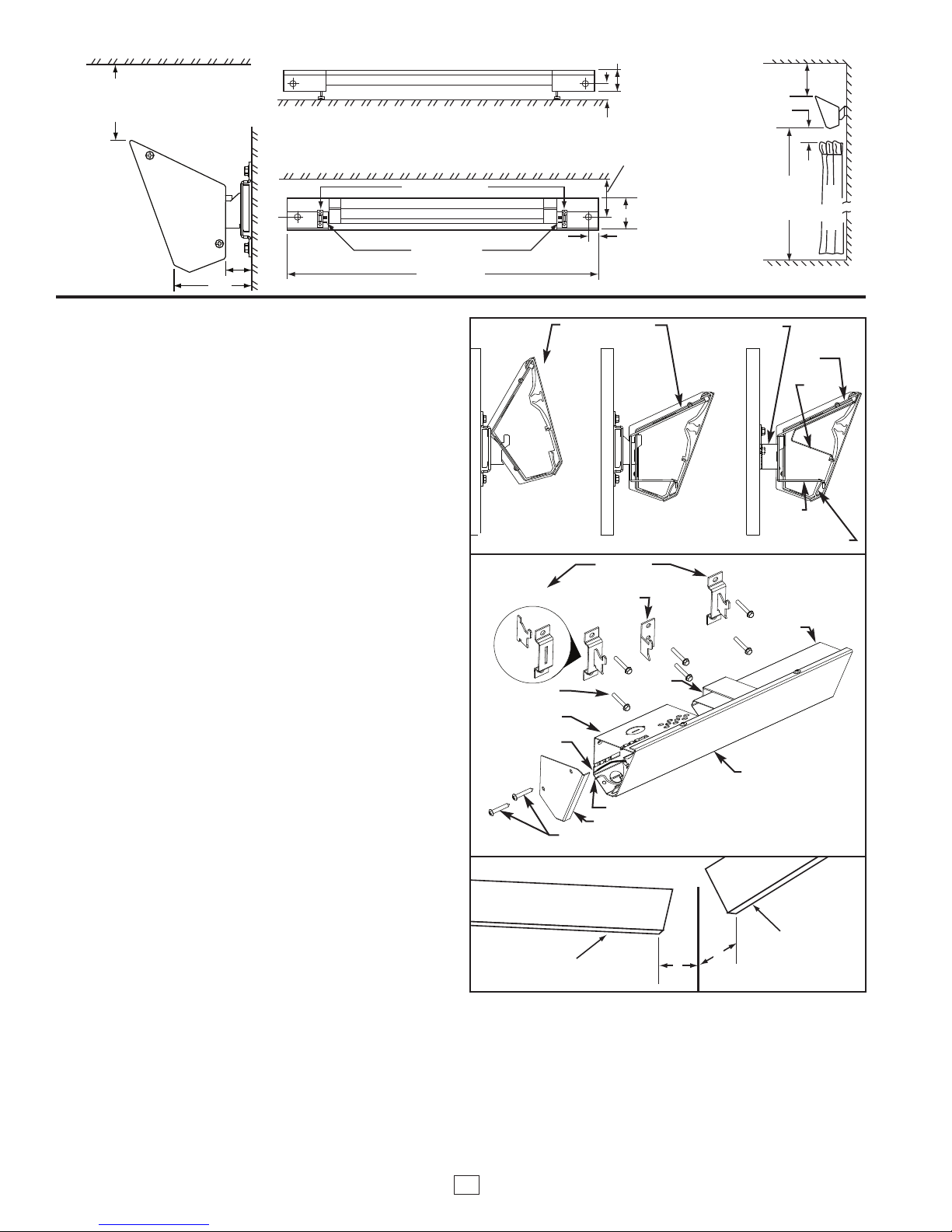
4
” (102 mm) MIN. (DRY WALL CEILINGS)
6
” (152 mm) MIN. (LAY IN OR VINYL
CEILINGS OR PLASTIC MOLDING)
1
“ (25.4 mm) MIN. BETWEEN BOTTOM
OF HEATER AND ANY FABRIC
6‘ MINIMUM
(1.83 m)
CLEARANCE
TO FLOOR
CURTAINS
CEILING
WALL
FLOOR
MOUNTING RESTRICTIONS
}
4” (102 mm)(DRY WALL CEILINGS)
6” (152 mm) LAY IN OR VINYL CEILINGS
OR PLASTIC MOLDING)
BACK VIEW
MOUNTING SLOTS
MOUNTING BRACKETS
34” TO 132”
(0.86 M to 3.35 M)
CEILING
WALL
3”
2”
TOP VIEW
4-3/16“ (106.4 mm)
1-1/2” (38.1 mm)
HEATERS TO BE MOUNTED
AT LEAST SIX (6) FEET
(1.83 M) FROM THE FLOOR.
MINIMUM CLEARANCES:
• 4” (102 mm) MIN. TO DRY WALL CEILING.
• 6” (152 mm) MIN. TO LAY-IN OR VINYL CEILING
OR PLASTIC MOLDING.
CEILING
2-1/2”
13/16”
Figure 1
HEATE R
HEATE R
4”
4”
MOUNTING THE HEATER (Continued)
4. To mount cove heater, attach center support bracket to the center
wall bracket by tilting the heater back and allowing the upper slot
to fall onto the bracket hook per Figure 2. Attach the junction
boxes to the end wall brackets in a similar manor. Bring the cove
heater forward to lock into place.
For 1500 to 1800 Watt Heaters:
The 1500 & 1800 watt cove heaters require the additional support of
(2) center wall brackets due to the extra length. The mounting steps
are similar to the 450 to 1200 watt cove heater with the following
exceptions:
1. After the approximate center location between the end wall brack-
ets has been determined, measure 30 inches (762 mm) on each
side of this location to determine the approximate location to
mount the center wall brackets. Locate a stud nearest each mark.
Use these studs for the center wall bracket locations. (Disregard
original 30 inch location marks)
2. Using the provided template, align the top of the template with the
ceiling and the center of the pre-punched holes with the bracket
marks on the wall. Choosing the proper bracket location holes,
mark the bracket pilot hole locations using the selected prepunched holes provided on the template. With the fasteners provided, mount the assembled end wall brackets and center wall
brackets to the wall. Measure the distance between the center
(slot) of the left end wall bracket and the hook of the left center
wall bracket. Add 3-5/8 inches (92 mm) to this (left end) value and
record it for the left center support bracket location on the cove
heater. Determine the distance between the center of the right
end wall bracket and the hook of the right center wall bracket.
Add 3-5/8 inches (92 mm) to this (right end) value and record it
for the right center support bracket placement on the cove heater.
3. Orient the cove heater face down on a protective flat surface.
Using the left end value recorded in step 2, measure this distance
from the left end of the cove heater and mark this location on the
back surface of the panel. Using the right end value recorded in
step 2, measure this distance from the right end of the cove
heater and mark this location on the back surface of the panel.
Slide the center support brackets to the marked positions on the
panel, aligning the center of the brackets with each mark.
4. To mount cove heater, attach center support brackets to the cen-
ter wall brackets by tilting the heater back and allowing the upper
slot to fall onto the bracket hook per Figure 2. Attach the junction
boxes to the end wall brackets in a similar manor. Bring the cove
heater forward to lock into place.
5. The cove heater can be wired from either end of the heater.
Install a cable clamp (supplied by others) in one of the knockouts
located in back of the junction boxes you plan to use. Insert the
power supply cable through the cable clamp allowing approximately 6” (152mm) of cable length to remain inside the box to
facilitate wiring. Add at least 2 inches of cable loop between wall
and knockout entering the junction box to allow for heater expansion.
ALIGN JUNCTION
BOX SLOT WITH
BRACKET HOOK
Figure 2
#10-16 X 1-1/2”
LONG SCREWS
JUNCTIONBOX
ELEMENT LEAD
Figure 3
MOUNTING HEATER
TO END BRACKET
ASSEMBLY
HEATER LOCKED IN
POSITION ON END
WALL BRACKET
END WALL
BRACKET ASSEMBLY
CENTER WALL
BRACKET
CENTER
SUPPORT
BRACKET
CROSSOVER LEAD
END CAP
#8-18 X 1” LONG SCREWS
CUTAWAY SHOWING
CENTER MOUNTING
BRACKET DETAILS
CENTER
SUPPORT
BRACKET
BACK WRAP
HEAT SHIELD
COVE HEATER
FRONT PANEL
OP
T
LANGE
F
BACK
WRAP
WIREWAY
Figure 4
6. Refer to wiring diagrams on next page.
7. Attach end caps (found in parts bag) as shown in Figure 3.
1. Heaters must be located so that the ends of each heater are
4 inches (102 mm) from side wall. See Figure 4.
2
INSTALLATION AT CORNER
Page 3

{
{
GREEN
GROUND
WIRE
POWER
SUPPLY
SINGLE UNIT WIRING – SUPPLY IN MIDDLE
IGHT HAND FIELD CONNECTION SHOWN. TO WIRE ON LEFT HAND SIDE:
R
1) SEPARATE ELEMENT LEAD FROM CROSS-OVER WIRE ON LEFT SIDE.
(
2) USING WIRE NUT, CONNECT LEAD WIRE TO CROSS-OVER WIRE ON RIGHT SIDE.
(
3) CONNECT L1 TO ELEMENT LEAD AND L2 (OR NEUTRAL) TO CROSSOVER WIRE
(
N LEFT SIDE.
O
LEMENT LEAD
E
20V - YELLOW
1
08V - BLUE
2
40V - RED
2
77V - BROWN
2
CROSS-OVER WIRE (BLACK 208/240V, WHITE 120/277V)
RED CROSS-OVER WIRE USED FOR MULTIPLE END CONNECTED HEATERS ONLY.
L1
L2
BLACK
RED
208 OR 240 VOLT MODELS
ELEMENT
WARNING:
CHECK HEATER NAMEPLATE AT
INSTALLATION TO VERIFY UNIT VOLTAGE RATING IS THE SAME AS THE SUPPLY VOLTAGE.
FACTORY
SUPPLIED
WIRE NUTS
(5 REQUIRED)
GREEN
GROUND
WIRE
SUPPLY
WIRING
POWER
SUPPLY
BLACK*
* Use white cross-over
wire on the heaters
rated 120V or 277V
L
LEMENT
N
WHITE
ED
R
120 OR 277 VOLT MODELS
E
ALL UNITS MAY BE WIRED FROM EITHER END.
HEATER GROUNDING WIRE FOR SUPPLY
GROUND CONNECTION FOUND ON EITHER END.
TWO UNIT WIRING – SUPPLY IN MIDDLE
TO GROUND
SEE TABLE 1 FOR EXPANSION DIMENSIONS
SUPPLY
BLACK*
SUPPLY
GROUND
CAUTION:
TOTAL LOAD MUST NOT EXCEED
16AMPS FOR INTERCONNECTED HEATERS.
TWO OR MORE HEATERS – SUPPLY AT END
GROUND
L1
(A)
SUPPLY
GROUND
(B)
SUPPLY
Figure 5. Heater Wiring
L2
N
L1
(A) 240 / 208 VOLT HEATERS (B) 120 VOLT OR 277 VOLT HEATERS
FOR GROUND CONTINUITY BETWEEN ADJACENT HEATERS USE GROUND WIRE PROVIDED.
SEE NOTES ABOVE FOR TWO UNIT WIRING – SUPPLY IN MIDDLE.
Black
Red
White
Red Red Red
Black
Red
White
Black
White
Red
Page 4

IMPORTANT INFORMATION
REPLACEMENT PARTS
Elements and aluminum extrusions are not replaceable. Due to the
intrinsic design of the cove heater, we are unable to furnish elements,
extrusions, wires, back shields, and junction boxes as replaceable parts,
however, the following parts kits are available.
Part Kit 1. Part number 3303-2032-000 for white cove heaters.
Part Kit 2. Part number 3303-2032-001 for Dove Grey cove heaters.
Part Kit 3. Part number 3303-2032-002 for Desert Tan cove heaters.
The above kit contains end caps, end brackets, center bracket, mounting template, and mounting hardware.
ACCESSORIES (Optional)
RCCT
RCCSPC
Integral Thermostat: Range 45-90ºF with positive off.
Splice Plate Assembly.
NAMEPLATE
E
DATE CODE
0904
774G LISTED
ROOM HEATER
MODEL NO.
COVE HEATER (PATENT PENDING)
APPAREIL DE CHAUFFAGE
ENCASTRÉ
RADIATOR EQUINERO DE TECHO
VOLTS:
WATTS: 450 AMPS 3.75
MARLEY ENGINEERED PRODUCTS
BENNETTSVILLE, SC 29512 USA
C4 512D
120 A.C. 60HZ
X
E
A
M
P
L
Specifications
Model No. Watts Voltage Amps (inches)
C4508D
C4512D
C4524D
C6008D
C6012D
C6024D
C6027D
C7508D
C7512D
C7524D
C7527D
C9008D
C9012D
C9024D
C9027D
C10508D
C10512D
C10524D
C10527D
C12008D
C12012D
C12024D
C12027D
C15008D
C15024D
C15027D
C18008D
C18024D
C18027D
450W 120V 3.7 34
600W 120V 5.0 47
750W 120V 6.2 59
900W 120V 7.5 71
1050W 120V 8.8 83
1200W 120V 10.0 94
1500W 240V 6.2 118
1800W 240V 7.5 132
208V 2.2 34
240V 1.9 34
208V 2.9 47
240V 2.5 47
277V 2.2 47
208V 3.6 59
240V 3.1 59
277V 2.7 59
208V 4.3 71
240V 3.7 71
277V 3.2 71
208V 5.0 83
240V 4.4 83
277V 3.8 83
208V 5.8 94
240V 5.0 94
277V 4.3 94
208V 7.2 118
277V 5.4 118
208V 8.7 132
277V 6.5 132
Length
All products manufactured by Marley Engineered Products are warranted against defects in workmanship and materials for one year from date of installation, except
LIMITED WARRANTY
heating elements which are warranted against defects in workmanship and materials for five years from date of installation. This warranty does not apply to damage
from accident, misuse, or alteration; nor where the connected voltage is more than 5% above the nameplate voltage; nor to equipment improperly installed or wired or
maintained in violation of the product’s installation instructions. All claims for warranty work must be accompanied by proof of the date of installation.
The customer shall be responsible for all costs incurred in the removal or reinstallation of products, including labor costs, and shipping costs incurred to return products to Marley Engineered Products Service Center.Within the limitations of this warranty, inoperative units should be returned to the nearest Marley authorized service center or the Marley Engineered Products Service Center, and we will repair or replace, at our option, at no charge to you with return freight paid by Marley. It is
agreed that such repair or replacement is the exclusive remedy available from Marley Engineered Products.
THE ABOVE WARRANTIES ARE IN LIEU OF ALL OTHER WARRANTIES EXPRESSED OR IMPLIED, AND ALL IMPLIED WARRANTIES OF MERCHANTABILITY
AND FITNESS FOR A PARTICULAR PURPOSE WHICH EXCEED THE AFORESAID EXPRESSED WARRANTIES ARE HEREBY DISCLAIMED AND EXCLUDED
FROM THIS AGREEMENT. MARLEY ENGINEERED PRODUCTS SHALL NOT BE LIABLE FOR CONSEQUENTIAL DAMAGES ARISING WITH RESPECT TO THE
PRODUCT, WHETHER BASED UPON NEGLIGENCE, TORT, STRICT LIABILITY, OR CONTRACT.
Some states do not allow the exclusion or limitation of incidental or consequential damages, so the above exclusion or limitation may not apply to you. This warranty
gives you specific legal rights, and you may also have other rights which vary from state to state.
For the address of your nearest authorized service center, contact Marley Engineered Products in Bennettsville, SC, at 1-800-642-4328. Merchandise returned to the
factory must be accompanied by a return authorization and service identification tag, both available from Marley Engineered Products. When requesting return authorization, include all catalog numbers shown on the products.
HOW TO OBTAIN WARRANTY SERVICE AND
WARRANTY PARTS PLUS GENERAL INFORMATION
1. Warranty Service or Parts
2. Purchase Replacement Parts
3. General Product Information
Note:
When obtaining service always have the following:
1. Model number of the product
2. Date of manufacture
3. Part number or description
1-800-642-4328
1-800-654-3545
www.marleymep.com
Part No. 5200-2668-005
ECR 39014
02/11
4
470 Beauty Spot Rd. East
Bennettsville, SC 29512 USA
 Loading...