

Page 1
•...•..•....•.......••..•...•
><
>
••
<
••••
>./
•••
>••
·.......i..·
·.......
..
·.........i
·.
>
•••.••••••••••••••••••••••••••••.•••
....
················1J······b········t·····S·····
.
.
--.-.
.:':;
:::<::::
<_:::-~::::~:
'.:::::::
::-:::::::-
-."
......................
··a·······
.
. .
-.'-
..
::-::"::
',:::
. : ::
:::.::
::::,.::'"
IN THIS SECTION
Electric Baseboard Heaters
HARRISAI~
SY-STEl\t1S,
I~C_
Heat:-ina
&....Air
Condit:ionina
Inst:allat:ion
&....Service
Page 2
i-::lo..
-
1
-
Electric Baseboard
Heaters
2500 & C2500 Series
Installation,
Operation
&
Maintenance
Instructions
IMPORTANT INSTRUCTIONS
GENERAL
This heater is designed to provide years of efficient, trouble free operation as a primary or supplementary heat source for comfort
heating
in
residential and commercial applications. Baseboard heaters must be thermostatically controlled for efficient, safe opera-
tion. A thermostat is not provided with this heater. However, a single or double pole thermostat accessory is available for installa-
tion into this heater at your place of purchase, or the heater may be connected
to
any suitable wall mounted thermostat that will
meet the electrical load requirements. Installation or use of this product in any manner not described herein will void the warranty
and could result
in
injury, damage to property, or permanent damage to heater.
~
WARNING
~
WHEN
USING
ELECTRICAL
APPUANCES,
BASIC
PRECAU-
TIONS
SHOULD
ALWAYSBEFOLLOWEDTOREDUCE
THE
RISK OF FIRE, ELECTRIC SHOCK, AND INJURY
TO
PERSONS,
INCLUDING
THE
FOLLOWING:
1. Read all instructions before installing or using the heater.
2. A heater has hot and arcing or sparking parts inside, Do not
useinareas where gasolineorflammable liquids are used
or stored.
3.
This heater is hot wheninuse. To avoid bums, do not let
bare skin touch hot surfaces. Keep combustible materials,
such as fumiture, pillows, bedding, papers, clothes, and curtains away from heater.
NAMEPLATE
DATE CODE
1009
4. To prevent a possible fire, do not block air intakes or
exhaust
in
any manner.
5.
Do not insert or allow foreign objects to enter any ventilation
or exhaust opening
as
this may cause an electric shock or
fire, or damage the heater.
6.
Serious injury or death could result from electric shock.
Make sure electrical power supply circuit coming to heater
is
disconnected at main disconnect or service panel before
installing or servicing this heater.
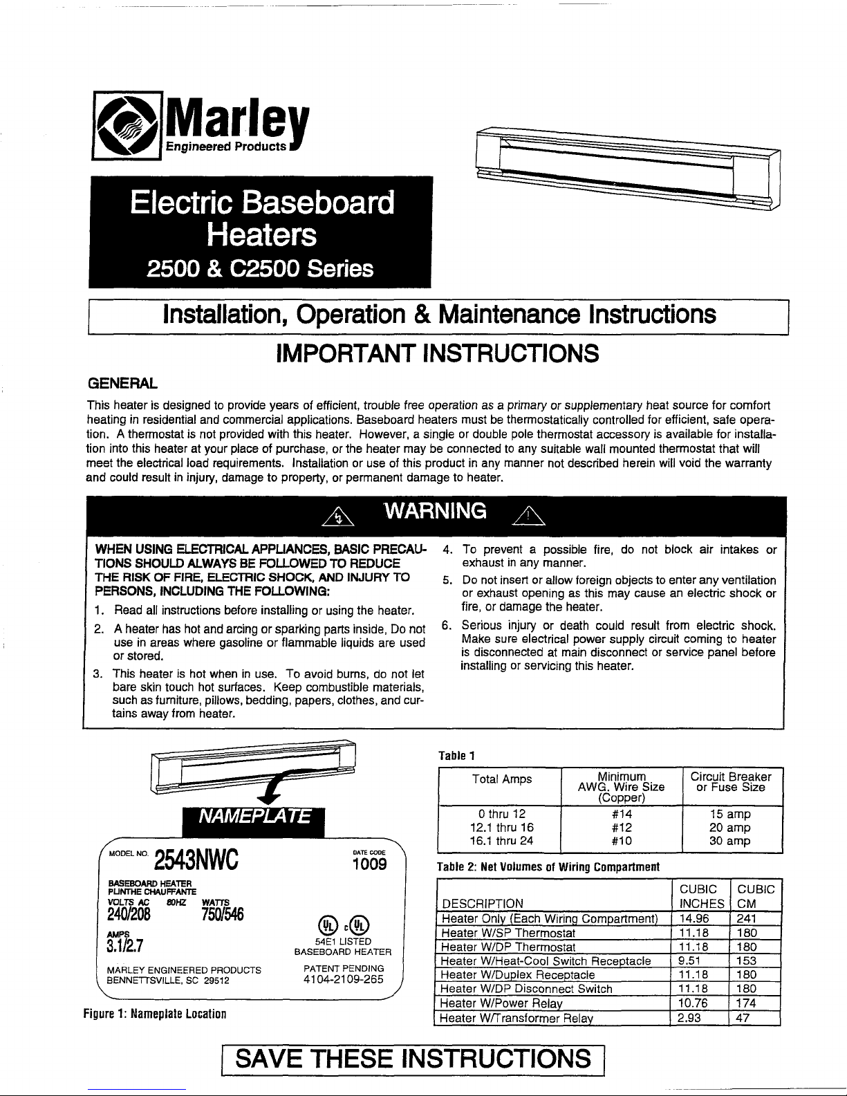
Table
1
Total Amps
Minimum Circuit Breaker
AWG. Wire Size
or Fuse Size
(Copper)
Othru
12
#14
15
amp
12.1 thru
16
#12
20 amp
16.1 thru
24
#10
30 amp
Table2:Net
VolumesofWiring
Compartment
BASEBOARD
HEATER
PUNTHE
CHAUFFANTE
VOLTS
AC 80HZ
WATTS
240/208
750/546
AMPS
3.1/2.7
MARLEY ENGINEERED PRODUCTS
BENNETTSVILLE,
SC
29512
Figure1:Nameplate
Location
@c@
54El
LISTED
BASEBOARD HEATER
PATENT PENDING
4104-2109-265
CUBIC CUBIC
DESCRIPTION INCHES CM
Heater Only (Each Wirinq Compartment)
14.96
241
Heater WISP Thermostat
11.18
180
Heater W/DP Thermostat
11.18
180
Heater W/Heat-Cool Switch Receptacle
9.51
153
Heater W/Duplex Receptacle 11.18
180
Heater W/DP Disconnect Switch
11.18
180
Heater W/Power RelaY
10.76
174
Heater Wffransformer Relav
2.93
47
ISAVE THESE INSTRUCTIONS I
Page 3

•
UNPACKING
HEATER
Check heaterto make sure it
has
not been damagedinship-
ping.
Do
not install or attempt to operate the heaterifdamaged.
Retum to place of purchase or file
claim
with freight carrier.
Important Note: Certain fabrics and materials discolor or may
become damaged by heat. Therefore, avoid installing heater
against vinyl wall coverings or below plastic or vinyl items such
as
blinds or vinyl drapes since these items may become dam-
aged
by
the heated air flowing from heater.
INSTALLATION
INSTRUCTIONS
CEILING
CEILING
.&
WARNING A
L
MIN.
1"
(25mm)
L
MIN
.1"
(25mm)
Example 2
DRAPES
MIN.fi
r(152mm)
T
.....--
HEATER
FLOOR
DRAPES
Example 1
-
ment
over
-
-
- -
-
- -
-
MIN.
1"
(25mm)
Figure2:Clearance
for
Drapery
Furniture:
maintain at least 6 inches
(152
mm) space between
furniture and heater to allow for proper air flow.
1.
Remove
Wiring
compartment cover at end of heater where
power supply cable is to enter (Figure
3). Determine desired
mounting location, position heater to wall and mark wall (or
floor) at location where power supply is to
enter heater.
Figure
3
NOTE: For most efficient operation locate heaters along outside
wall under windows. Position heater
so
it can be secured to
wall stud. Power cable must enter heater through built
in
cable
clamp or one of the knockouts provided in wiring compartment.
2. Drill hole
in
wall (or floor) at desired location for power supply
entry. Install power supply wiring to heater and thermostat
location as determined
by
thermostat option selected. Allow
approximately 10 to 12 in (254mm to 305mm) of wire at
heater for connections.
3.
If any accessories are to be used with this heater, refer to
installation instructions provided with the accessory for proper installation and wiring. Visit www.marleymep.com for
instructions
on
some common accessories.
4. Wireway Cover - Commercial Baseboard Only
a.
The wireway cover is a factory installed feature of Marley
commercial baseboard heaters. Two cables or four individual conductors plus two ground wires may be routed
through the wireway. Refer to page
1,
Table 1 for wire
size and current loads.
b.Togain access to wireway, lay heater face down and
remove the screws holding the wireway from the back of
the heater. Remove the knockouts in the channel areas of
both terminal boxes.
c.
Insert the plastic bushings from the parts
kit
(in
wiring
compartment)
in
the knockout holes.
d.
Wire heater according to wiring diagramsinFigure
5.
Attach the wireway cover using the screws.
Front
C
Wiring
compart
cover
Screw
TO REDUCE
THE
RISK OF FIRE AND ELECTRIC SHOCK
OR INJURY
TO
PERSONS, OBSERVE THE FOLLOWING:
1.
Serious injury or death could result from electric shock.
Make sure electrical power supply circuit coming to heater
is
disconnected at main disconnect or service panel before
installing this heater.
2.
Wiring procedures and connections must beinaccordance
with
the National Electrical Code (NEC) and local codes.
Refer to Wiring Diagrams Figure
5.
Make sure all electrical
connections are tight to prevent possible overheating. Use
Copper Supply Wire Only.
3. Verify the electrical power supply voltage matches the volt-
age
rating as printedonthe heater nameplate - see Figure
1.
CAUTION - Never connect a heatertoa voltage greater than
the nameplate
voltage as this will damage the heater and
could
causeafire"
4.
Do
not install the heater against combustible low-density
cellulose
fiberboard surfaces, against or below
Vinyl
wall
coverings, or below any materials that may be damaged by
heat such as
Vinyl
or plastic blinds, curtains, etc.
5.
Do
not install heater belowanelectrical convenience recep-
tacle (outlet).
6. CAUTION - Heater Operates at High Temperatures. Keep
Electrical Cords (including telephone and computer cables),
Drapes, and Other Furnishings Away From Heater. For efficient and safe operation, we recommend maintaining a min-
imum of 6 inches (152 mm) clearance above and
in
front of
the heater at all times. See Figure 2 for minimum clearance
requirements for drapery.
7.
To reduce the risk of fire,donot store or use gasoline or
other flammable vapors or liquids in the vicinity of the
heater.
8.
Do
not install heater upside down orinany position other
than
as
showninthis manual. Caution label with word
"TOP" must
be
at the top when heater is installed.
9.
Do
not recess heaterinwall or install heater inside any type
enclosure as this will cause heater to overheat and could
create a hazard.
10. When mounting heater, if bottom mounting holes are used
(see Figure 4), make sure screws
do
not damage supply
wiring
in
the area behind heater.
11.
Do
not remove or bypass the safety limit controlasthis
could allow heater to become a fire hazard - see Figure
4.
12.
When
using RSA Transformer Relay Accessory, supply
wiring provided
in
compartment where this accessory is
installed, must
be
rated
90°C
minimum.
Minimum
Clearances
Heaterto Floor: heater maybemounted directlyonfinished
1ror, if desired, above floor (such
as
above the baseboard).
, to 3/4 inch (19 mm)ofcarpeting may be installed up to and
around heater as long
as
it does not obstruct the air flow.
Heater to Drapery: do not install heater where curtains or drapery will contact the heater.
See
Fig. 2 for required minimum
clearances.
2
Page 4

5.
Loosen screwinbuilt-in cable clamp (Figure4)or remove
desired knockout from heater wiring compartment. Install
power cable into wiring compartment allowing at least
6
in
(153mm) of cable for connection to heater. To install two
power cables using the built-in cable clamp, bend tab covering second hole
up
and back to rear wall of wiring compartment. If built-in cable clamp is not used. install approved
cable restraint (not included) in desired knockout.
NOTE:
cross stamped mounting perforations are provided
in
back of heater enclosure above heating element at mounting
screw locations, see Figure
4.
6.
Position heater at desired location and attach to wall using
wood screws or appropriate hardware. Locate studs and
drive screws into studs where possible. For heaters up to 6
feet (1.8
m)
in length, one screw at each end is adequate.
For longer units,
an
additional screwincenter is required.
Tighten screws and then loosen screws at least
14
tum to
allow heater to expand and contract during use. If unit
is
mounted above floor, two additional mounting holes are provided at each end below the heating element (see Figure 4).
Install an additional screw at each end for stability making
sure to loosen each screw at least
14
turn.
7. Connect the supply cable
grounding wire to the bare copper
pigtail in wiring compartment.
8.
Follow the desired wiring diagram, as showninFigure5,to
connect the power supply to the heater using approved wire
nuts.
NOTE:
When accessories are installed, use wiring diagram
supplied with the accessory.
9.
If front cover was removed, reinstall by hooking the top edge
on the support bracket(s). Then push down to latch onto the
support bracket(s).
10.Replace wiring compartment cover(s).
11.Follow instructions accompanying thermostat for installation
and wiring thermostat. Visit www.marleymep.com for typical
thermostat wiring diagrams.
OPERATING
INSTRUCTIONS
1. This heater must be properly installed before itisused.
2.
After the baseboard system has been completely installed,
all thermostats should be tumed to LOW or NO HEAT.
Turn on breakers, wait 3 to 5 minutes and check to see that
none of the heaters are operating.
If
operating, disconnect
power and check wiring. If none are operating then turn
thermostats to highest position and wait 3 to 5
minutes.
Check to see that all heater(s) are operating. Should any not
be operating, disconnect power and check wiring.
3. Allow entire system to operate steadily for 1/2 hour. This
should remove oily residue from manufacturing. (Some
smoking may occur).
4. Select the setting for comfort on all thermostats.
5.
A safety limit controlisprovided to tum off the heater automatically if it
is
blocked or otherwise overheats due to
an
abnormal condition-see Figures 4 and
5.
DO
NOT
bypass or
remove this safety device from the electrical circuit-see
Warning
11
on page2.During normal use, this safety control
should not operate. If you find that this controlisoperating,
make sure the heater
is
not being blocked. If it continues to
cycle the heater
off,
disconnect power to heater and have it
checked and repaired by a qualified electrician.
3
Safety
limit
DO
NOT
BYPASS
o
I~~~III
_______
-.:..Q
~Bottom
mounting
holes
Figure4:Left
Side
Wiring
Compartment
Shown
MAINTENANCE
INSTRUCTIONS
Your heater will give you years of service and comfort with only
minimum care. To assure efficient operation follow the simple
instructions below.
A
WARNING
A
1.
Serious injury or death could result from electric shock.
Make sure electrical power supply circuit coming to heater
is disconnected at main disconnect or service panel before
servicing this heater. Allow heater to cool before cleaning
to prevent a possible bum.
2. Use care when cleaning element fins to avoiding damaging
fins. Note also that fins are sharp and may cause cuts so
avoid contact.
1. The user
can perform some basic cleaning of the heater. All
other servicing is to
be
done by qualified service personnel.
2. Because of the convection heating principle which depends
upon a circulation
of
air through the finned element, dust will
collect between the fins. The heater should
be
cleaned regu-
larly for maximum efficiency.
3.
To clean heating element fins, first remove both wiring compartment covers and the front cover. Using a vacuum cleaner
or compressed air, remove the dust and lint from the aluminum heating element fins while being careful not to damage the fins.
4. The painted heater cabinet may be cleaned using a slightly
damp cloth. Do not use abrasive cleaners or waxes
as
these
may damage the finish or leave a residue that will discolor.
5.
Replace front cover (making sure itislatched in place at
each element support bracket and at each end) and two
wiring compartment covers (using the two screws
prOVided),
restore power and check heater
for
proper operation.
Painting
Ifitbecomes necessarytorepaint heater, use only a quality
enamel paint suitable for metal surfaces following the instructions provided with the paint. DO NOT paint the heating element
or safety limit capillary tube. Repaint
only the exterior of the
cabinet.
Page 5

~
GROUND
FACTORY
WIRING
--
AElD
WIRING - - - - -
FACTORY
WIRING
--
FIELD
WIRING
- - - - -
L2
SA
UMIT
WHITEORBLACK
Left
End
Supply
Wiring
GROUND
GRNO
Right
End
Supply
Wiring
GROUND
GROUND
**
NOTE:
White for
120V&277V
Black
for
all others
/~...,..,..,-{)"''''-r
Orange
wire
nut
(Disconnect
for
right
side
supply
wiring)
WHITE
RBlACK
~
GROUND
Orange
wire
nut--+
....
6-....,.,...,.--"
I
(Disconnect
for
lett
side
supply
wiring)
"'-t--------------t
.....
GROUND
':' J J _
GROUND
FACTORYWlRfNG
--
I I
ORND
AELDWlRlNG - - - - - I I
Ll
L2
*
Note:
Heater
element
leads
are
color
codedbyvoltage-
Yellow
120V
Blue
208V
Red
240V
Brown
277V
Connection
For
Adjacent
Heaters
Factory
Wiring
Shown
Safety
limit
in
left side r==:-=:-------------......,
DO
NOT
BYPASS
WHITEORBlACK**
Figure5:Wiring
Diagrams
Note:
For
multiple heaters on one circuit, the heaters must be wired in parallel
LIMITED
WARRANTY
All products manufactured by Marley Engineered Products are warranted against defectsinworkmanship and materials for one year from date of installation. except
heating elements which are warranted against defects
in
workmanship and materials for ten years from date of installation. This warranty does not applytodamage from
accident, misuse.
or
alteration;
nor
where the connected voltage is more than 5% above the nameplate voltage; nor to equipment improperly installed or wired or
maintained in violation of the product's installation instructions. All claims for warranty work must
be
accompaniedbyproof of the dateofinstallation.
The customer shall be responsible tor all costs incurred
in
the removalorreinstallationofproducts, including labor costs, and shipping costs incurredtoreturn products
to Marley Engineered Products Service Center. Within the limitations of this warranty. inoperative units should be returned to the nearest Marley authorized service center or the Marley Engineered Products Service Center. and we will repair
or
replace. at our option,atno charge to you with return freight paidbyMarley.Itis agreed that
such repair
or
replacement is the exclusive remedy available from Marley Engineered Products.
THE ABOVE WARRANTIES ARE IN LIEU OF
AlL
OTHER WARRANTIES EXPRESSED OR IMPLIED, AND ALL IMPLIED WARRANTIESOFMERCHANTABILITY AND
FITNESS FOR A PARTICULAR PURPOSE WHICH EXCEED THE AFORESAID EXPRESSED WARRANTIES ARE HEREBY DISCLAIMED AND EXCLUDED FROM
THIS AGREEMENT. MARLEY ENGINEERED PRODUCTS SHALL NOT BE LIABLE FOR
CONSEQUENTiAl
DAMAGES ARISING WITH RESPECT TO THE
PRODUCT. WHETHER BASED UPON NEGLIGENCE, TORT. STRICT LIABILITY. OR CONTRACT.
Some states do not allowthe exclusion
or
limitationofincidental or consequential damages, so the above exclusionorlimitation
may
not
apply
to you. This warrantygives
you
specific legal rights. and you
may
also have other rights which vary from state to state.
For the address
of
your nearest authorized service center. contact Marley Engineered ProductsinBennettsville. SC. at 1-800-642-4328. Merchandise returned to the factory must be accompanied by a return authorization and service identification tag. both availabie from Marley Engineered Products. When requesting return authorization.
include all catalog numbers shown on the products.
HOWTOOBTAIN
WARRANTY
SERVICE
AND
WARRANTY
PARTS
PWS
GENERAL
INFORMATION
1. Warranty Service or Parts HIOD-642-4328
2. Purchase Replacement Parts 1-80D-654-3545
3.
General Product Information www.marleymep.com
Note:
When obtaining service always have the following:
1.
Model number of the product
2. Date of manufacture
3. Part numberor description
470
BelIuty
Spot
Ad.
East
Bennettsville.
SC
29512 USA
Part No. 5200-2194-010
ECR39036
02/11
4
 Loading...