

Marley 935, 958, 945, 968, 978 Instructions Manual
Dear Owner,
Congratulations! Thank you for purchasing this new heater manufactured by a division of Marley Engineered
Products. You have made a wise investment selecting the highest quality product in the heating industry.
Please carefully r ead and follow the installation and maintenance dir ections shown in this manual. You should
enjoy years of efficient heating comfort with this product from Marley Engineered Products... the industry’s
leader in design, manufacturing, quality and service.
... The Employees of
Marley Engineered Products
Installation & Maintenance Instructions
WARNING
!
Read carefully - These instructions are written to help
you prevent difficulties that might arise during installation
of heaters. Studying the instructions first may save you
considerable time and money later. Observe the following procedures and cut your installation time to a minimum.
TO REDUCE RISK OF FIRE AND ELECTRIC SHOCK:
1. Disconnect all power coming to the heater at main
service panel before wiring or servicing.
Note: More than one disconnect may be required.
2. All wiring must be in accordance with national and
local electric codes and the heater must be grounded.
3. Verify the power supply voltage coming to heater
matches the ratings printed on the heater nameplate
before energizing.
4. This heater is hot when in use. To avoid burns, do
not let bare skin touch hot surfaces.
5. Do not insert or allow foreign objects to enter any
ventilation or exhaust opening as this may cause
electric shock, fire, or damage to heater.
6. Do not block air intakes or exhaust in any manner.
Keep combustible materials at least 24” (610 mm)
away from heater. Keep drapes at least 6” (153 mm)
above top of front discharge grille. Do not use
drapes above top discharge units. Do not install
behind doors, furniture, towel rack, or boxes.
7. A heater has hot and arcing (sparking) parts inside.
Do not use in areas where gasoline, paint, or flammable
liquids are used or stored.
8. Use this heater only as described in this manual. Any
other use not recommended by the manufacturer
may cause fire, electric shock, or injury.
9. This heater is not approved for use in corrosive
atmospheres such as marine, green house, or chemical storage areas.
10.
FOR DUCT CONNECTED HEATERS, Do not
exceed 0.2” wg. external static pressure and do not
mount heater on end panels.
11. Do not use
OPTIONAL 0-100% OUTSIDE AIR
DAMPER with bottom air inlet.
SAVE THESE INSTRUCTION SHEETS
900 Series
Cabinet Unit Heaters
Model B
1
KW
2
3
4
5
6
7
8
4
6
8
10
12
14
16
6
8
10
12
14
16
6
9
12
15
18
21
24
8
12
16
20
24
28
32
BTU/hr
6,826
10,239
13,652
17,065
20,478
23,891
27,304
13,652
20,478
27,304
34,130
40,956
47,785
54,608
20,478
27,304
34,103
40,956
47,782
54,608
20,478
30,717
40,956
51,195
61,434
71,673
81,912
27,304
40,956
54,608
68,260
81,912
95,564
109,216
Series
935
945
958
968
978
Cabinet
Length
(in)
35
45
58
68
78
CFM*
250
500
750
750
1,000
208
1 ph
60 Hz
10
15
20
25
30
34
39
20
30
40
48
59†
68†
78†
30
40
48
59†
68†
78†
31
45
60
74
88
n/a
n/a
41
60†
79†
n/a
n/a
n/a
n/a
208
3 ph
60 Hz
6
9
12
15
17
20
23
12
18
23
29
34
40
46
18
23
29
34
40
46
19
27
35
44
52†
60†
69†
24
36
47
58†
69†
80†
91†
240
1 ph
60 Hz
9
13
17
22
26
30
34
18
26
34
43
51†
59†
68†
26
34
43
51†
59†
68†
27
39
52†
64†
77†
89†
n/a
36
52†
69†
86†
n/a
n/a
n/a
240
3 ph
60 Hz
6
8
10
13
15
18
20
11
16
20
25
30
35
40
16
20
25
30
35
40
16
24
31
38
45
52†
60†
21
31
41
50†
60†
70†
79†
277
1 ph
60 Hz
8
12
15
19
22
26
30
16
23
30
37
44
52†
59†
23
30
37
44
52†
59†
24
34
45
56†
67†
78†
n/a
31
46
60†
74†
n/a
n/a
n/a
347
1 ph
60 Hz
7
9
12
15
18
21
24
13
18
24
30
36
41
47
18
24
30
36
41
47
19
28
36
45
n/a
n/a
n/a
25
37
48
n/a
n/a
n/a
n/a
380
3 ph
60 Hz
4
5
7
8
10
11
13
7
10
13
16
19
22
25
10
13
16
19
22
25
11
16
20
25
29
34
38
14
20
27
33
39
45
n/a
480
3 ph
60 Hz
3
4
6
7
8
9
10
6
8
11
13
16
18
20
8
11
13
16
18
20
9
13
16
20
24
27
31
12
17
21
26
31
36
41
600
3 ph
60 Hz
3
4
5
6
7
7
8
5
7
9
11
13
15
17
7
9
11
13
15
17
8
11
13
16
19
22
25
10
14
18
21
15
29
33
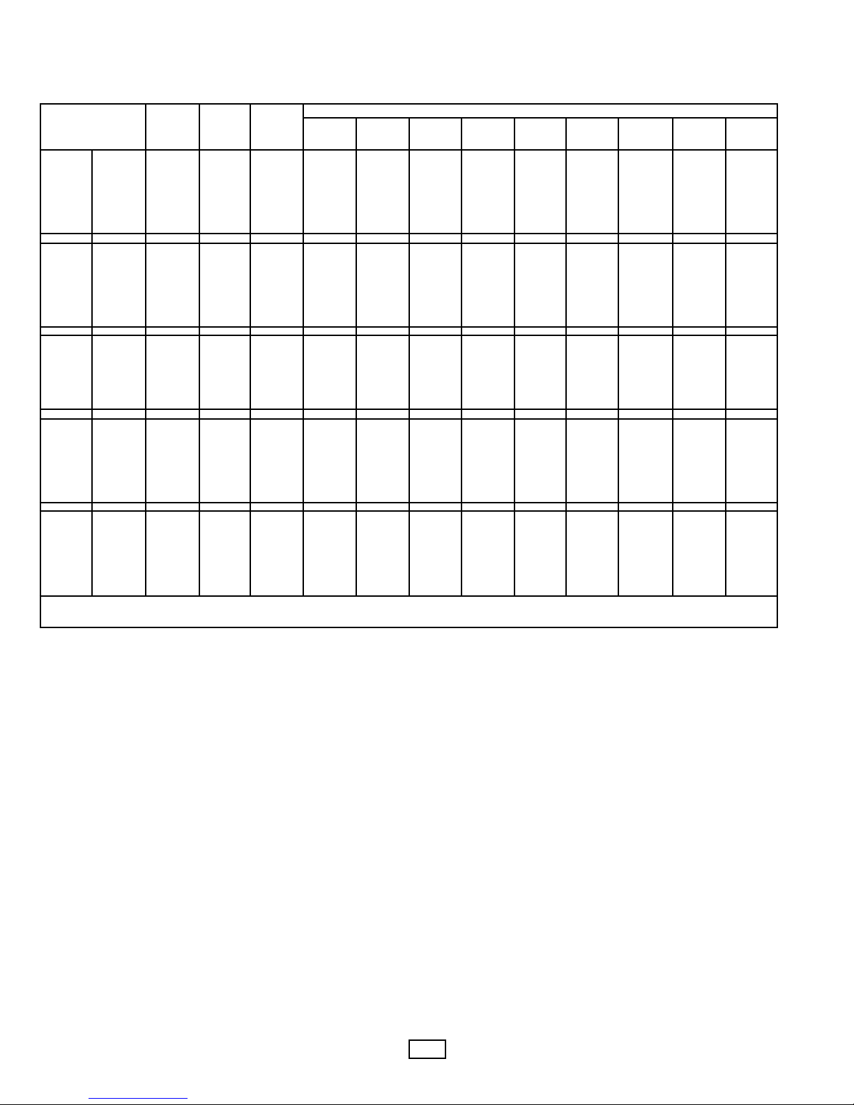
HEATING
CAPACITY
† - CIRCUIT BREAKERS or FUSED DISCONNECT required
* - Value shown for HIGHSPEED on two speed units
Specifications
Total Line Amperage (includes motor amps)
2

3
General Information
900 Series Cabinet Unit Heaters are designed and UL & cUL
Listed to be applied as Standard Free Air heaters with both
louvered intake and louvered discharge panels for recess or
surface installation: a) on the floor, with front inlet and up flow
air movement in the up flow, down flow, left or right direction or
b) on the ceiling, or Ducted (0.2” wg external static pressure)
flange for direct connection of field supplied ductwork to the
inlet, discharge, or both inlet and discharge. Ducted heaters
can be installed for recess or surface installation: a) on the
floor, with front inlet and up flow air movement, b) on the wall,
with air movement in the up flow or down flow direction or c)
on the ceiling.
See Figure 1 for Mounting Clearances.
Note:
Keep all furniture or any other blocking material at least
24” (610mm) away from front of heater.
When draperies are used, hang them so that when in use they
are at least 6” (153mm) above the top of front discharge
heater.
Do not use draperies with top discharge heaters.
See Figure 2 for Mounting Dimensions
See Figure 3 for Duct Collar Dimensions and Installation
Details.
FLOOR MOUNTING
1.
Heaters with front inlet and up flow air movement
may be mounted directly on any floor surface including carpeting. Where wall to wall carpeting is
installed after heater installation the carpeting can be
run up to the front and around the heater body. See
Figure 1 for mounting clearances.
2. Heaters can be mounted on either end with air movement
left or right directly on any floor surface including carpeting.
See Figure 1 for mounting clearances.
3. If optional kick plate is not used, proceed to “HEATER
INSTALLATION” section.
INSTALLATION OF OPTIONAL 900 SERIES BASE
KIT
1. If desired, the heaters may be mounted off the floor with
optional kick plate panel.
2. Align panel on bottom of heater (Inlet side only.)
3. There should be a 1” (25mm) space from the panel to the
front and sides of the heater.
4. Match drill .140” (3.55 mm) diameter holes in the bottom of
the heater and secure with screws provided.
5. Proceed to “HEATER INSTALLATION” section.
WALL OR CEILING RECESS MOUNTING
1. Create on opening in the wall 26-5/8” (676mm) high by the
width of the heater plus 1/4” (6.4mm).
Example: If the heater
was 68 inches long, the opening should measure
26-5/8” high x 68-1/4” long).
2. The depth of the recess will vary with the desired amount
of heater recess.
3. Proceed to “HEATER INSTALLATION” section.
INSTALLATION OF OPTIONAL
900 SERIES RECESS TRIM KIT
1. Determine depth of heater recess.
2. Align recess trim frame so that the trim frame front edge
will touch wall when heater is installed.
3. Match drill .140” (3.55mm) diameter holes in all four sides of
the heater and secure trim frame with screws provided.
4. Proceed to “HEATER INSTALLATION” section.
HEATER INSTALLATION
1. Rough-in electrical wiring. See Figure 2 for knockout locations.
2. Remove the proper knockout in the heater or punch the
proper size hole in the bottom or right side of the heater as
shown in Figure 2.
3. Remove the front cover by rotating the lock(s) counterclockwise (ccw).
4. Remove Top (Discharge) Louver Panel by removing 2
screws (one on each end) that attach the louver panel to
the end panels.
5. Refer to Figure 3 for location of mounting holes.
6. Mark and drill holes for heater attachment in wall or ceiling.
7. Install heater in opening and tighten screws (field supplied)
to insecure tight fit of the heater against the mounting surface.
NOTE: Tightening the heater against an irregular wall
will cause distortion of the back panel of the heater. If
this is the case, shims should be used behind the back
panel to keep it straight.
8. Reinstall the Top (Discharge) Louver Panel by sliding the
panel into the heater. Position the panel tabs of the louver
panel to rest on the top of the lip of the heater back.
Position the louver panel top even with the top of the end
panels. Tap the louver panel at the top front (both sides) to
seat the panel. Reinstall 2 screws (one on each side) that
attach louver panel to the end panels.
9. WIRING - See wiring section.
10.After wiring is complete, insure that the control box cover is
closed and fastened and that the filter is installed.
11.Adjust the thermostat to the desired set point.
12.Adjust the heat selector to the heat and fan speed desired.
13.Replace front cover and secure by turning the locks clockwise (cw) until tight. Replace plug buttons provided.
14.Leave the heater running a few hours before making any
further change in thermostat setting.
CAUTION
TO PREVENT HEATER FROM FALLING AND CAUSING
PERSONAL INJURY, EACH FASTENER, AS APPLIED,
SHOULD HAVE THE HOLDING POWER OF AT LEAST 100
POUNDS (45 kg).
!
DUCTED APPLICA TIONS
1. See Figure 3 for duct flange size and location.
2. Duct collars have been factory located (Bottom inlet, Front
inlet, Top discharge, Front discharge) as ordered.
3. To change duct collar location:
A. Heater duct panels are supplied with a duct collar attached
to one surface and a blank-off plate attached to the other
surface. The location of the duct collar and the blank-off
plate can reversed.
B. Remove screws holding blank-off plate and remove blank-
off plate.
C. Remove screws holding duct collar and remove duct collar.
D. Position duct collar to location desired, align screws holes,
insert and tighten screws to secure duct collar to duct
panel.
E. Position blank-off plate to location desired, align screw
holes, insert and tighten screws blank-off plate to duct
panel.
4. Position field ductwork to outside of heater duct flange.
5. Mark and drill starting holes in duct and flange.
6. Install and tighten screws (field supplied) to provide a
secure seal.
OPTIONAL
0-100% OUTSIDE AIR DAMPER
1. Flange brackets for the rear mounted duct collar are packaged unassembled in the heater carton.
2. See Figure 2 for location of damper opening.
3. Position the top flange bracket with the flange at the top of
the damper opening and holes in the flange align with
holes in the cabinet back.
4. Attach flange to cabinet with screws provided.
5. Position and attach remaining three (3) flange brackets
around damper opening.
6. Position field ductwork to outside of flange brackets.
7. Mark and drill starting holes in duct and flange.
8. Install and tighten screws (field supplied) to provide a
secure seal.
OPERATION OF OPTIONAL
0-100% OUTSIDE AIR DAMPER
1. Controls, consisting of an “OPEN-CLOSED” switch and 0100% positioning potentiometer, are located on the control
panel door.
2. Place switch in OPEN position.
3. Adjust potentiometer to percentage of outside air desired.
4. The damper will remain open to the position selected until;
the “OPEN-CLOSED” switch is moved to the closed position, the “ON-OFF switch (if installed) is turned off, the
night set back relay (if installed) is in the night position, or if
there is a power failure.
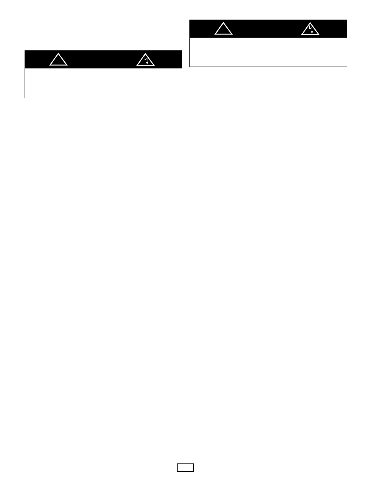
TO REDUCE RISK OF FIRE AND ELECTRICAL
SHOCK:
DO NOT EXCEED 0.2” WG EXTERNAL STATIC
PRESSURE. DO NOT MOUNT HEATER ON END PANEL
(LEFT OR RIGHT AIR FLOW).
WARNING
!
TO REDUCE RISK OF FIRE AND ELECTRICAL
SHOCK: DO NOT USE 0-100% OUTSIDE AIR DAMPER
OPTION WITH BOTTOM AIR INLET. USE ONLY FRONT AIR
INLET WITH 0-100% OUTSIDE AIR DAMPER OPTION.
WARNING
!
4
 Loading...