

Marley 500 Maintenance Manual
Series 500 Ceiling Mounted
Fan Forced Heater
Electrical Accessories
Installation Instructions
CAT. NO. ACCESSORY ELECTRICAL RATING REMARKS
T Single Pole Internal Thermostat; 25A; 120-277 VAC Res. -
Temp Range: 40°F - 95°F 720 Pilot Duty
24R Control Relay; 24 VAC Holding Coil Inductive Amps: 7.0 @ 120 - 277 VAC. Time Delay: 45 - 60 sec.;
R12 Control Relay; 120 VAC Holding Coil Inductive Amps: 7.0 @ 120 - 277 VAC. Time Delay: 45 - 60 sec.;
DS Supply Power Disconnect Switch 30A (MAX Load 24A) 208 - 600 VAC, 3 Pole, 10 -
TR4 Transformer and Relay Transformer: 208/240 VAC primary; 24 VAC Time Delay: 45 - 60 sec.;
TR7 Transformer and Relay Transformer: 277 VAC primary; 24 VAC Time Delay: 45 - 60 sec.;
Resistive Amps: 25 @ 120 - 277 VAC. to close when energized.
Resistive Amps: 25 @ 120 - 277 VAC. to close when energized.
secondary. - Relay: 24 VAC Holding Coil to close when energized.
secondary. - Relay: 24 VAC Holding Coil to close when energized.
WARNING
!
THIS INSTRUCTION SHEET CONTAINS VITAL INFORMATION
FOR THE PROPER INSTALLATION, USE AND EFFICIENT
OPERATION OF THE HEATER. CAREFULLY READ THE MANUAL BEFORE INSTALLATION, OPERATION, OR CLEANING
OF THE HEATER. FAILURE TO ADHERE TO THE INSTRUCTIONS COULD RESULT IN FIRE, ELECTRIC SHOCK, DEATH,
SERIOUS PERSONAL INJURY OR PROPERTY DAMAGE.
WARNING
!
MAKE SURE ALL POWER IS DISCONNECTED AT SUPPLY
BEFORE INSTALLING.
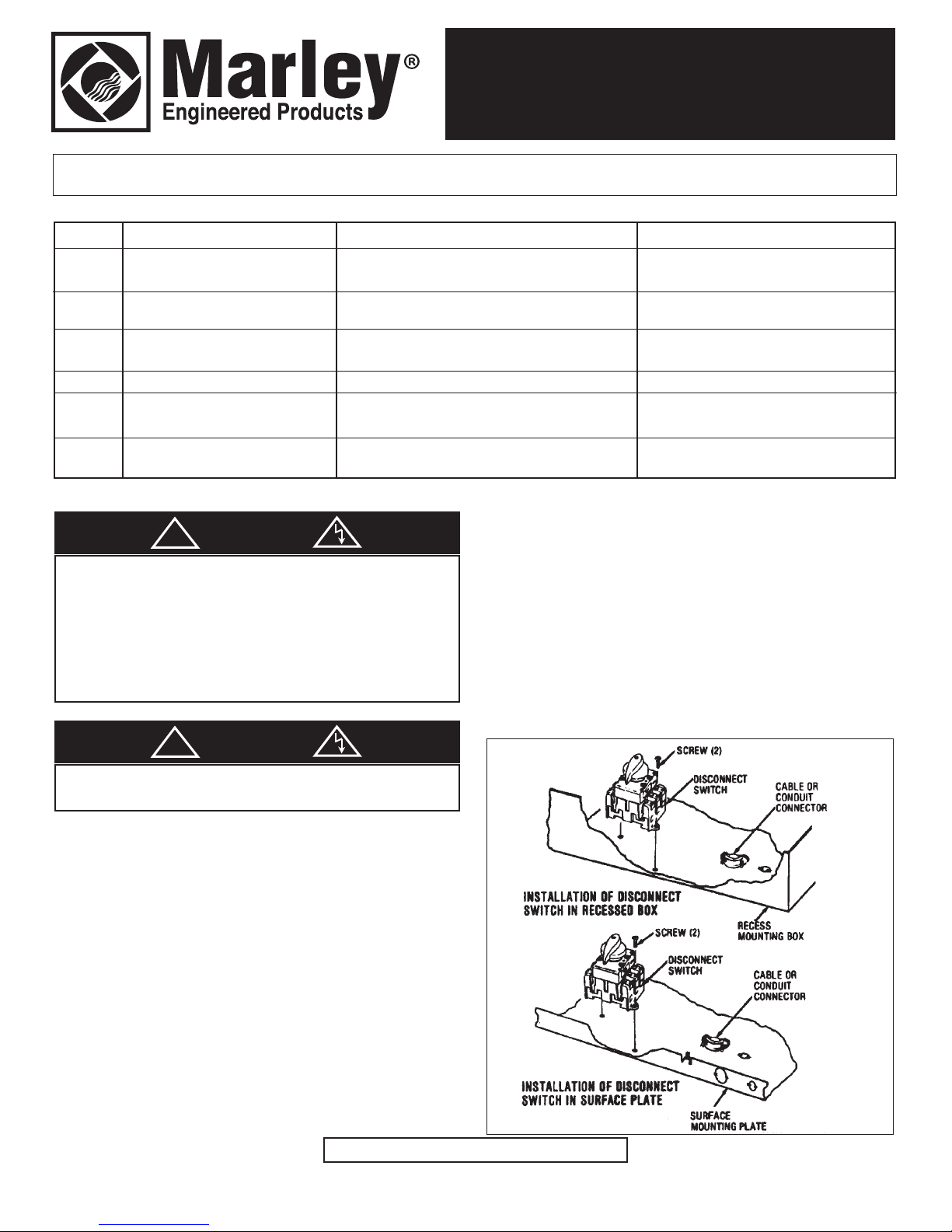
INSTALLATION OF POWER DISCONNECT SWITCH (DS)
Surface Mount and Recessed Mount Except T-Bar
Mounting:
1. Install disconnect switch in the surface mounting plate or
recess box as shown in the heater installation instructions
and Figure 1 with the terminals marked L1, L2 and L3 toward
the knockout.
(and T3 for three phase) from the disconnect switch to the
power block on the heater. (See Wiring Diagram, Figure 3).
6. Turn disconnect switch clockwise to energize circuit.
T-Bar Mounting:
1. Install disconnect switch in the recess box as shown in the
heater installation instructions and Figure 1 with the terminals
marked L1, L2, and L3 toward the knockout.
2. Remove and discard the wire from the terminal marked T3 on
the disconnect switch if the power supply is single phase.
2. Remove and discard the wire from the terminal marked T3 on
the disconnect switch if the power supply is single phase.
3. Install field wiring to the disconnect switch terminals marked
L1 and L2 (and L3 for three phase).
4. Install heater as shown in the heater installation instructions.
5. Remove wiring cover from front of heater and wire T1 and T2
40485 03/15 5200-2070-004
Figure 1
SAVE THESE INSTRUCTIONS
3. Remove wiring cover from front of heater and wire T1 and T2
!
(and T3 for three phase) from the disconnect switch to the
power block on the heater. See Wiring Diagram, Figure 3.
4. Install heater as shown in the heater installation instructions.
5. Install field wiring to the disconnect switch terminals marked
L1 and L2 (and L3 for three phase).
6. Turn disconnect switch clockwise to energize circuit.
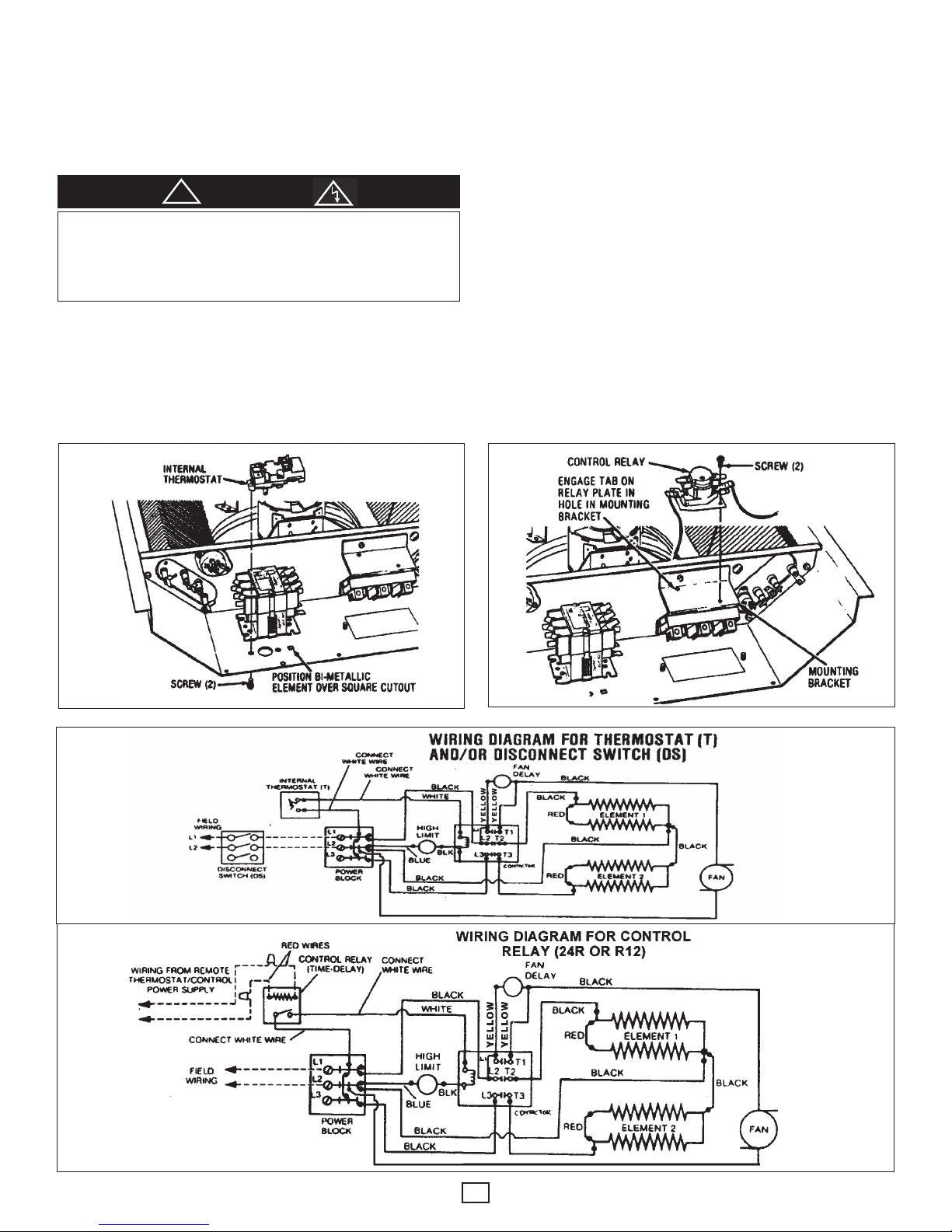
INSTALLATION OF CONTROL RELAY
(24R OR R12)
1. Install the Control Relay as shown in Figure 4.
NOTE: Be sure that the tab on the control relay plate is securely
engaged in the large hole in the mounting bracket.
2. To wire the relay, refer to the wiring diagram, Figure 5, and
proceed as follows:
CAUTION
TO AVOID POSSIBLE ELECTRICAL SHOCK, BE SURE ELECTRICITY IS TURNED OFF AT MAIN SWITCH BEFORE WIRING. ALL
WIRING MUST BE IN ACCORDANCE WITH THE NATIONAL ELECTRICAL CODE REQUIREMENTS. ALL CONTROL WIRING MUST BE
NEC CLASS 1 RATED 90° MIN.
INSTALLATION OF INTERNAL THERMOSTAT (T)
1. Install the Internal Thermostat in the heater as shown in
Figure 2.
2. Connect heater white wires to “L2” and “cycle” terminals on
the thermostat as shown in the wiring diagram, Figure 3.
NOTE: Push connectors securely onto the terminals to assure
proper connection.
a. Wire the internal control circuit by connecting the heater
WHITE wires to the terminals at the top of the relay.
NOTE: The control relay requires externally supplied voltage to
operate: 24 VAC 24R and 120 VAC for R12.
b. Wire the external control circuit by connecting two field
control wires (of proper voltage) to the two RED wires
from the relay base, using two wire nuts (provided).
3. For night setback operation, refer to wiring diagram, Figure 6.
NOTE: The control relay must be energized for day operation.
Figure 2
Figure 3
Figure 4
Figure 5
2
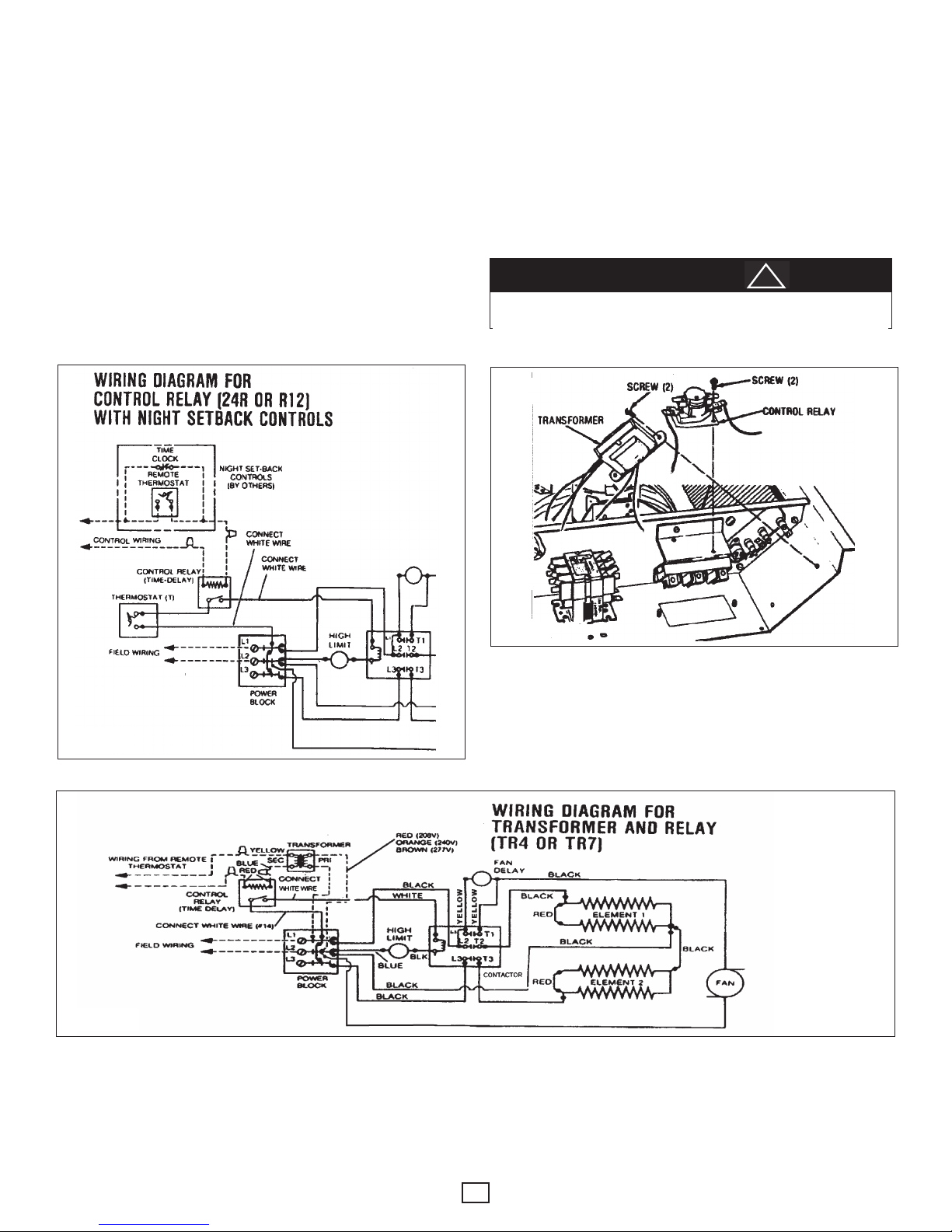
INSTALLATION OF TRANSFORMER AND RELAY
!
(TR4 OR TR7)
1. Install the Transformer and Relay as shown in Figure 7.
NOTE: Be sure that the tab on the relay plate is securely
engaged in the large hole in the mounting bracket.
2. To wire the transformer and relay, refer to the wiring diagram,
Figure 8, and proceed as follows:
d. Connect the Black wire (primary) from the transformer
to power block L1 terminal.
e. (For TR4 only) - Connect the RED wire (208V) or the
ORANGE wire (240V) from the transformer to terminal
L2 of the power block. Clip off and tape the end of the
unused transformer wire.
f. (For TR7 only) - Connect the BROWN wire (277V) from
the transformer to terminal L2 of the power block.
3. For night setback operation, refer to wiring diagram, Figure 9.
a. Connect the heater WHITE wires to the terminals at the
top of the relay.
b. Connect the BLUE transformer wire to one of the RED
wires from the relay base using a wire nut (provided).
c. Connect the other RED wire from the relay base and
the YELLOW transformer wire to the remote low voltage
thermostat (by others) wires.
NOTE: The control relay must be energized for day operation.
CAUTION
TRANSFORMER VOLTAGE MUST MATCH HEATER VOLTAGE (INDICATED ON HEATER NAMEPLATE).
Figure 7
Figure 6
Figure 8
3
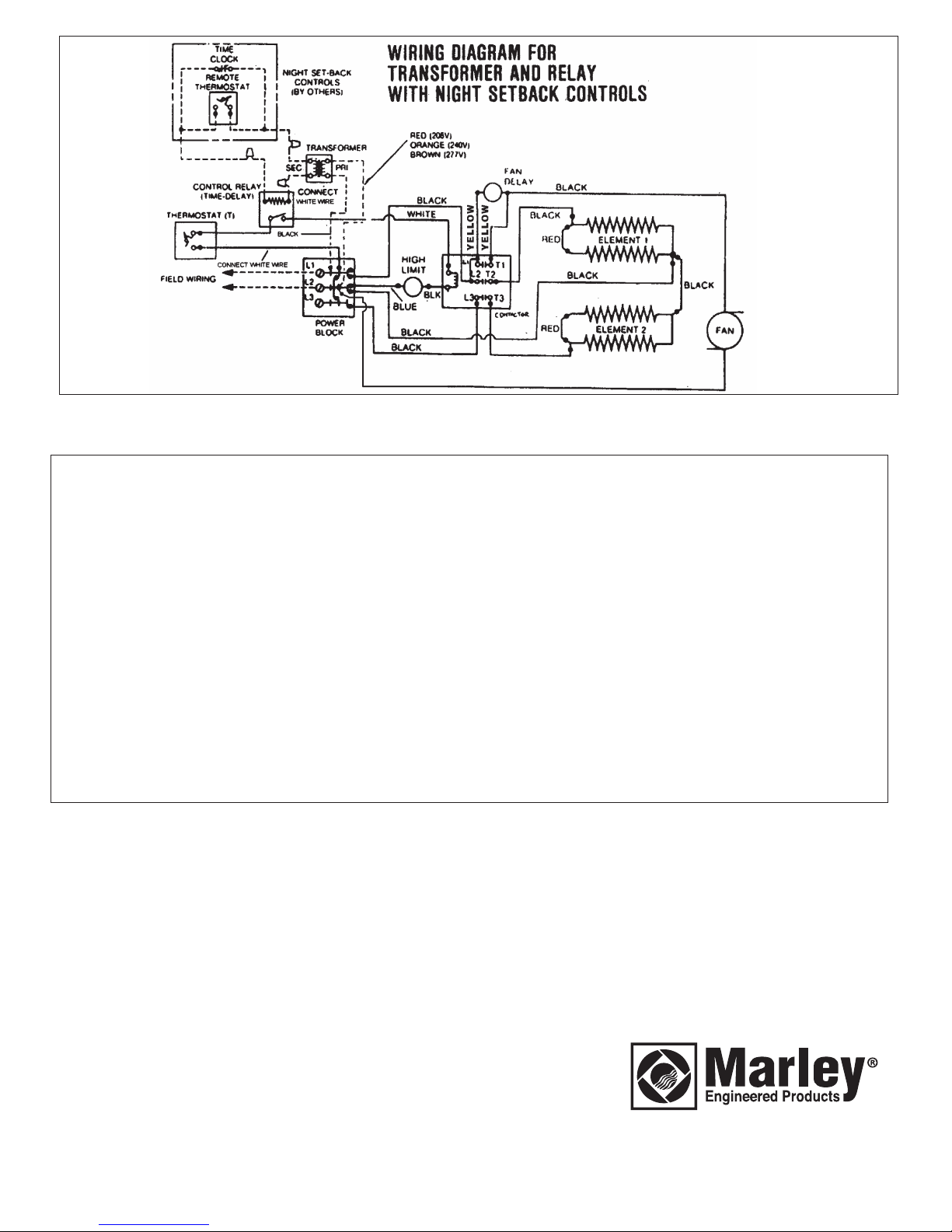
Figure 9
LIMITED WARRANTY
All products covered by this instruction sheet are warranted against defects in workmanship and materials for one year from date of
installation. This warranty does not apply to damage from accident, misuse, or alteration; nor where the connected voltage is more than
5% above the nameplate voltage; nor to equipment improperly installed or wired or maintained in violation of this instruction sheet. All
claims for warranty work must be accompanied by proof of the date of installation.
The customer shall be responsible for all costs incurred in the removal or reinstallation of products, including labor costs, and shipping
costs incurred to return products to a Marley Engineered Products Service Center, and we will repair or replace, at our option, at no
charge to you with return freight paid by Marley. It is agreed that such repair or replacement is the exclusive remedy available from
Marley Engineered Products.
THE ABOVE WARRANTIES ARE IN LIEU OF ALL OTHER WARRANTIES EXPRESSED OR IMPLIED, AND ALL IMPLIED WARRANTIES OF MERCHANTABILITY AND FITNESS FOR A PARTICULAR PURPOSE WHICH EXCEED THE AFORESAID EXPRESSED
WARRANTIES ARE HEREBY DISCLAIMED AND EXCLUDED FROM THIS AGREEMENT. MARLEY ENGINEERED PRODUCTS
SHALL NOT BE LIABLE FOR CONSEQUENTIAL DAMAGES ARISING WITH RESPECT TO THE PRODUCT, WHETHER BASED
UPON NEGLIGENCE, TORT, STRICT LIABILITY, OR CONTRACT.
Some states do not allow the exclusion on limitation of incidental or consequential damages, so the above exclusion or limitation may
not apply to you. This warranty gives you specific legal rights, and you may also have other rights which vary from state.
For the address of your nearest authorized service center, contact Marley Engineered Products, 470 Beauty Spot Road East,
Bennettsville, SC 29512 USA. Merchandise returned to the factory must be accompanied by a return authorization and service identification tag, both available from the above location. When requesting return authorization, include all catalog numbers shown on the
products.
HOW TO ORDER REPAIR PARTS
In order to obtain any needed repair or replacement parts,
warranty service or technical information, please contact Marley
Engineered Products Service Center toll-free by calling 1-800642-HEAT.
When ordering repair parts, always give the information listed
as follows:
1. The Part Number
2. The Model Number
3. The Part Description
4. Date of Manufacture
5200-2070-004
470 Beauty Spot Rd. East
Bennettsville, SC 29512 USA
ECR 40485
3/15
 Loading...