

Page 1
1235, 2435 Series
Fan Driven
Wall Heaters
Read Carefully - These instructions are written to help
you prevent difficulties that might arise during installation of
heaters. Studying the instructions first may save you considerable time and money later. Observe the following procedures and cut your installation time to a minimum.
1. To prevent electrical shock, disconnect all power coming
to heater at main service panel before wiring or servicing.
2. All wiring must be in accordance with the National and
Local Electrical Codes and the heater must be grounded
as a precaution against possible electric shock.
3. Verify the power supply voltage coming to heater matches the ratings printed on the heater nameplate before
energizing.
4. This heater is hot when in use. To avoid burns, do not let
bare skin touch hot surfaces.
5. Do not insert or allow foreign objects to enter any ventilation or exhaust opening as this may cause an electric
shock, fire, or damage to the heater.
6. To prevent a possible fire, do not block air intakes or
exhaust in any manner. Keep combustible materials, such
as crates, drapes, etc., away from heater. Do not install
behind doors, furniture, towels, or boxes.
7. A heater has hot and arcing (sparking) parts inside. Do
not use it in areas where gasoline, paint, or flammable
liquids are stored.
8. Use this heater only as described in this manual. Any
other use not recommended by the manufacturer may
cause fire, electric shock, or injury to persons.
9. This heater is not approved for use in corrosive atmospheres, such as marine, green house, or chemical storage areas.
WARNING
SAVE THESE INSTRUCTIONS
Dear Owner,
Congratulations! Thank you for purchasing this new heater manufactured by a division of Marley
Engineered Products. You have made a wise investment selecting the highest quality product in the heating industry. Please carefully read the installation and maintenance directions shown in this manual.
You should enjoy years of efficient heating comfort with this product from Marley Engineered Products...
the industry’s leader in design, manufacturing, quality and service.
... The Employees of
Marley Engineered Products
Installation & Maintenance Instructions
1
File #E21609
!
Page 2
UNPACKING
Unpack carefully. Inspect for loose, missing or damaged
parts. In the event of missing components or hidden damage
immediately contact your distributor or the delivering carrier
concerning discrepancies. The motor / fan assembly has
been carefully factory balanced. Care should be taken when
handling to avoid damage resulting in unnecessary vibration
and noise.
GENERAL
The wall heaters provide fast supplemental room heat. The
fan draws cool air in through the round opening in the grille
frame and directs it across the nickel chromium elements for
discharge through the rectangular top opening. An over-heat
protective device automatically shuts the heater OFF if the
discharge is blocked or an unsafe temperature rise is
encountered for any reason. Heaters are equipped with manual reset thermal over-heat protectors. On some models, the
manual reset is backed-up with a thermal fuse. The grille is
“finger-proof”” and can be removed for cleaning. The faceplate under the knob has a “finger-proof” clear Mylar covering which can be removed for a shiny appearance.
INST ALLATION
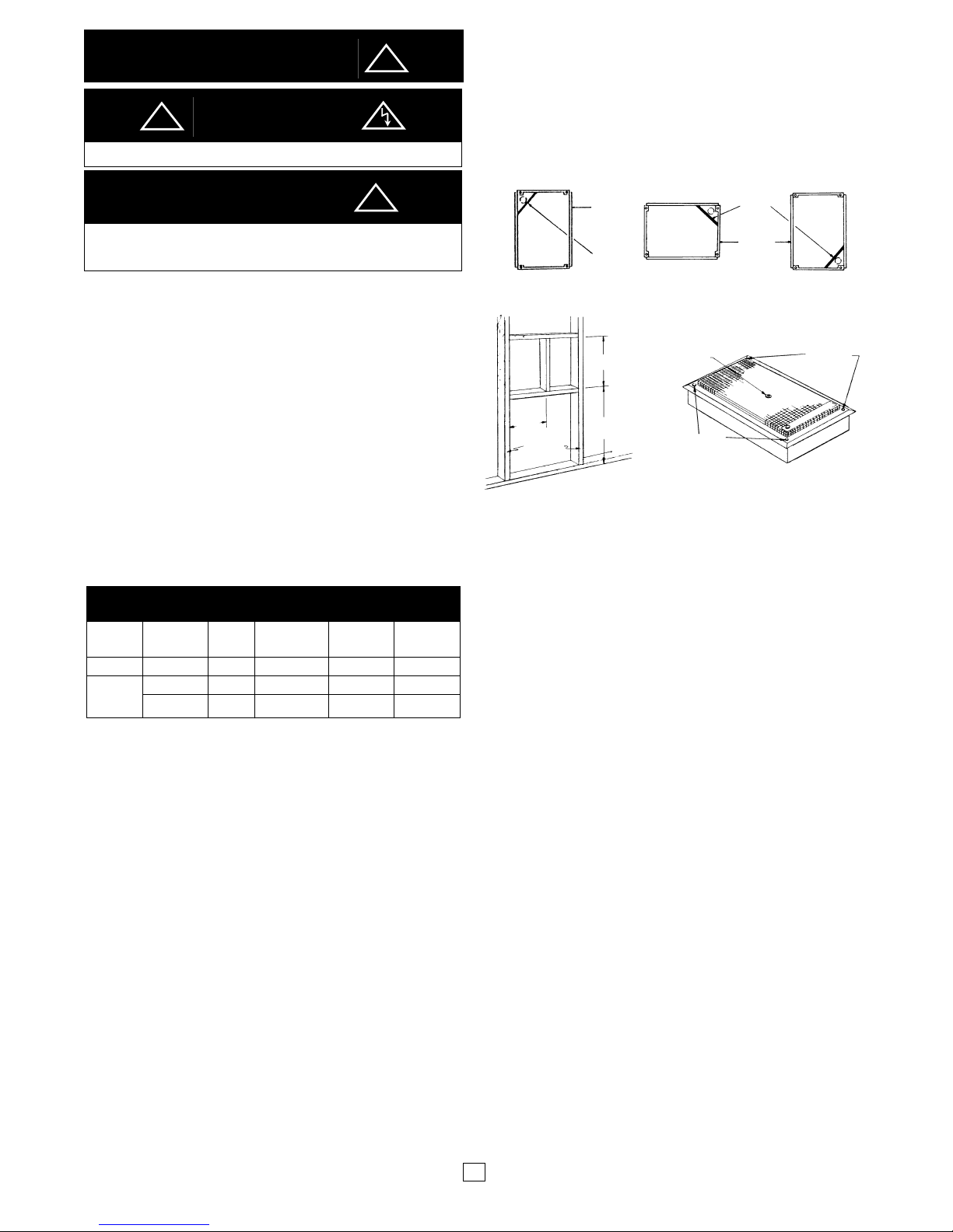
NOTE: Unit may be installed vertically or horizontally in the wall
stud space. This unit is for wall mounting only. A 14 1/2 x 9” wall
opening is required. If recess mounting is impractical, use 414
surface mounted housing (not furnished).
Bottom of heater should be a minimum of 18 inches above
finished floor.
1. HORIZONTALMOUNTING: (See Figure 1B)
a. MAKE SURE THAT OUTLET CORNER IS A T THE TOP
RIGHTHAND CORNER. In new construction place roughin box between studs at desired height, and using wood
screws, secure it to studs, making sure that outer edges
will be flush with finished wall. Bring in service lead through
proper knock-out hole and attach ground lead to screw
provided.
b. For installation in existing walls, select desired location,
ascertain location of studs and cut away wall using roughin box as a pattern for hole size. Bring in service lead
through proper knock-out hole and attach ground lead to
screw provided. THEN, secure rough-in box to studs
keeping outer edges flush with wall surface.
2. VERTICAL MOUNTING (See Fig. 1C)
a. MAKE SURE THAT OUTLETCORNER IS AT THE
BOTTOM RIGHT HAND CORNER. Toe-nail two 2 x 4”
headers, 14-3/8 inches apart at desired height (see Fig. 2).
b. Proceed as outlined in step 1a or 1b above.
3. Connect service leads to heater (see Figure 4 or 5). Make
sure all wiring conforms to National Electrical Code as well as
all applicable local codes.
4. Assemble heater into rough-in box using the four screws
supplied (see Figure 3).
SURFACE MOUNTING
If surface mounting adapter 414 is used to mount this heater,
follow mounting instructions packed with the adapter in conjunction with these instructions.
FIG. 1 MOUNTING ROUGH-IN BOX
OPERA TION
1. Set the thermostat to its fully clockwise position.
2. When room reaches comfort level, turn thermostat knob
counter-clockwise until the heater cuts off. Heater will cycle
automatically around this present temperature. To increase
temperature, turn knob clockwise. T o decrease, turn counterclockwise.
3. This unit is equipped with a manual-reset, high temperature
limit switch. If no heat is delivered with thermostat fully
clockwise, check reset button in center of grille. Push red
button in with a toothpick or similar piece of wood. If reset
kicks back out immedi
ately or will not stay in, have heater
checked by a qualified electrician
.
LIMIT SWITCH
1. This unit is equipped with a manual-reset, high temperature
limit switch. If no heat is delivered with the thermostat set fully
clock-wise, turn thermostat fully counterclockwise, and check
red reset button in center of front plate.
2. In order for the heater to operate, the limit switch must be reset.
Using a toothpick or similar piece of wood, push button IN
where it should remain.
3. Turn thermostat fully clockwise and repeat above steps when
heater resumes normal operation.
4. If heater still does not function, or if after a 10-20 minute cooldown period the button will not reset (remain IN), have the
heater checked by a qualified electrician.
NOTE: Due to the sensitivity of the limit switch, it may have
tripped from vibration during shipment. It may be necessary
to reset switch prior to initial start-up of the heater.
MAINTENANCE — Six Months
WARNING: Open circuit breaker for circuit supplying heater
before attempting any maintenance or repairs. Lock or tag
circuit breaker panel door. Failure to do so could result in
serious electrical shock, burns or possibly death.
a. Loosen screws securing heater assembly to housing and
remove heater assembly.
b. Vacuum or wipe dust from inside of heater . Take caution not to
bend or otherwise damage heater fan, blade or other
components
c. Reassemble heater.
2
MODEL VOLTS HZ TOTAL WATTS BTU/H
AMPS
1235 120 60 12.5 1500 5120
240 60 6.3 1500 5120
208 60 5.4 1125 3843
2435
DIMENSIONS OVERALL • Height - 15 5/8” • Width - 10”
• Depth - 3 3/4”
IMPORTANT
CAUTION
WARNING
DO NOT BLOCK HEATER IN ANY MANNER!
TO REDUCE THE RISK OF FIREOR ELECTRICAL SHOCK, DO
NOT USE THIS HEATER WITH ANY SOLID STATE SPEED
CONTROL DEVICE.
SPECIFICATIONS
ROUGH-IN
BOX
MANUAL
RESET BUTTON
SCREW
8B X 1 1/4”
SCREW
8B X 1 1/4”
14-3/8” MIN.
9-1/8”
16” O.C.
STUDS
18” MIN. TO
FINISHED FLOOR
ROUGH-IN
BOX
OUTLET
CORNER
OUTLET
CORNER
HORIZONTAL
VERTICAL
1A
1B
1C
FIG. 2 - HEADER LOCATION FIG. 3 - SECURING HEATER
!
!
!
Page 3

3
FIG. 4 WIRING DIAGRAM FOR MODEL 1235 FIG. 5 WIRING DIAGRAM FOR MODELS 2435
1500 WATTS - 120V - 60Hz
*ITEMS NOT LISTED ARE NOT AVAILABLE AS A REPLACEMENT ITEM.
REPLACE COMPLETE HEATER ASSEMBLY. (REF. NO. 139)
PARTS LIST MODELS
1235 & 2435
BLACK
WHITE
GROUND
THERMOSTAT
HEATING ELEMENTS
LIMIT
SWITCH
FAN
MOTOR
REF. MODEL
NO. DESCRIPTION QTY. USED ON
103 Rough-In Box 1 ALL
139 Element Assembly, 1 ALL
220 Thermostat Assembly w/Lead ALL
224 Knob, Black 1 ALL
226 Limit Switch, Manual Reset 175F 1 ALL
227 Reset Bracket 1 ALL
242 Motor Assy w/Terminals 1 ALL
247 Fan Blade 1 ALL
325 Grille, Aluminum 1 1235, 2435
Grille Almond 1 1235, 2435
550 Thermal Fuse 109 C, 15 AMPS 1 2435, 2435P
120 VOLT
SUPPLY
MOTOR
THERMOSTAT
LIMIT
SWITCH
HEATER
ASSEMBLY
1500/2000 WATTS - 240/208V - 60Hz
BLACK
GROUND
RED
THERMOSTAT
THERMAL
FUSE
HEATING ELEMENTS
FAN
MOTOR
LIMIT
SWITCH
MOTOR
240/208 VOLT
SUPPLY
THERMOSTAT
LIMIT
SWITCH
HEATER
ASSEMBLY
THERMAL
FUSE
Page 4

LIMITED WARRANTY
All products manufactured by Marley Engineered Products are warranted against defects in workmanship and materials for one year from date of installation,
except heating elements which are warranted against defects in workmanship and materials for five years from date of installation. This warranty does not apply
to damage from accident, misuse, or alteration; nor where the connected voltage is more than 5% above the nameplate voltage; nor to equipment improperly
installed or wired or maintained in violation of the product’s installation instructions. All claims for warranty work must be accompanied by proof of the date of
installation.
The customer shall be responsible for all costs incurred in the removal or reinstallation of products, including labor costs, and shipping costs incurred to return
products to Marley Engineered Products Service Center. Within the limitations of this warranty, inoperative units should be returned to the nearest Marley
authorized service center or the Marley Engineered Products Center, and we will repair or replace, at our option, at no charge to you with return freight paid by
Marley. It is agreed that such repair or replacement is the exclusive remedy available from Marley Engineered Products.
THE ABOVE WARRANTIES ARE IN LIEU OF ALL OTHER WARRANTIES EXPRESSED OR IMPLIED. AND ALLIMPLIED WARRANTIES OF
MERCHANTABILITYAND FITNESS FOR A PARTICULAR PURPOSE WHICH EXCEED THE AFORESAID EXPRESSED WARRANTIES ARE HEREBY
DISCLAIMED AND EXCLUDED FROM THIS AGREEMENT. MARLEY ENGINEERED PRODUCTS SHALLNOT BE LIABLE FOR CONSEQUENTIALDAMAGES
ARISING WITH RESPECT TO THE PRODUCT, WHETHER BASED UPON NEGLIGENCE, TORT, STRICTLIABILITY, OR CONTRACT.
Some states do allow the exclusion or limitation of incidental or consequential damages, so the above exclusion or limitation may not apply to you. This warranty
gives you specific legal rights, and you may also have other rights which vary from state to state.
For the address of your nearest authorized service center, contact Marley Engineered Products in Bennettsville, SC, at 1-800-642-4328. Merchandise returned to
the factory must be accompanied by a return authorization and service identification tag, both available from Marley Engineered Products. When requesting return
authorization, include all catalog numbers shown on the products.
HOW TO ORDER REPAIR PARTS
In order to obtain any needed repair or replacement
parts, warranty service or technical information, please
contact Marley Engineered Products Service Center tollfree by calling 1-800-642-HEAT .
When ordering repair parts, always give the information listed as follows:
1. The Part Number
2. The Model Number
3. The Part Description
4. Date of Manufacture
03-02
Part No. 5200-2538-001
4
ECR 35194
Heater does not come on. 1. Thermostat set too low, (too far counter-clockwise). 1. Turn the thermostat knob clockwise until heater
operates.
2. Circuit breaker in distribution panel not closed. 2. Close circuit breaker.
3. Circuit breaker in distribution panel does not stay * 3. A short circuit exists in the heater wiring.
closed.
4. Resettable temperature limit switch in heater not closed. 4. Manual close limit switch (See Operation
Section - Step 3.) *If limit switch will not stay in,
have heater checked.
5. Open in wiring in heater . * 5. Open main circuit breaker . Check wiring continuity.
6. Thermostat * 6. Open main circuit breaker to heater, jumper across
thermostat terminals. Close main circuit breaker .
If heater operates, thermostat should be replaced.
Remove jumper after opening main circuit breaker.
7. Thermal Fuse (Applicable units only) * 7. Open main supply circuit to heater. Check thermal
fuse. If blown, determine cause and correct. Replace
thermal fuse.
Fan blade does not turn. 1. Jammed fan blade. 1. Remove fan blade obstruction.
2. Leads not connected to fan motor. * 2. Connect fan motor leads.
3. Winding in fan motor open. * 3. Replace fan motor.
4. Locked motor bearing. 4. Oil motor bearings; if bearings do not unlock, replace
motor.
Heater discharges smoke. 1. Dust, dirt and lint accumulate inside of heater. 1. Clean heater. See Six Month Maintenance Section
for cleaning instructions.
Heater fan operating, but does 1. Open heater element. 1. Replace heating unit assembly.
not discharge warm air. 2. Wire loose from element assembly. * 2. Replace wire.
3. Heater connected to wrong electrical service voltage. * 3. Check supply voltage.
* WARNING: MUST BE PERFORMED BY QUALIFIED ELECTRICAL SERVICE PERSONNEL ONLY. CONTACTMANUFACTURER
FOR INSTRUCTIONS ON RETURNING UNITTO AN AUTHORIZED SERVICE CENTER.
TROUBLE-SHOOTING CHART
PROBLEM POSSIBLE CAUSE CORRECTIVE ACTION
470 Beauty Spot Rd. East
Bennettsville, SC 29512 USA
 Loading...