

Page 1
Adjustable Speed
Controls
OPERATING INSTRUCTIONS
MODELS: 12003, 12008, 12012, and 27708
READ CAREFULLY BEFORE ATTEMPTING TO INSTALL, OPERATE, OR SERVICE ADJUSTABLE
SPEED CONTROLS!
RETAIN INSTRUCTIONS FOR FURTHER REFERENCE.
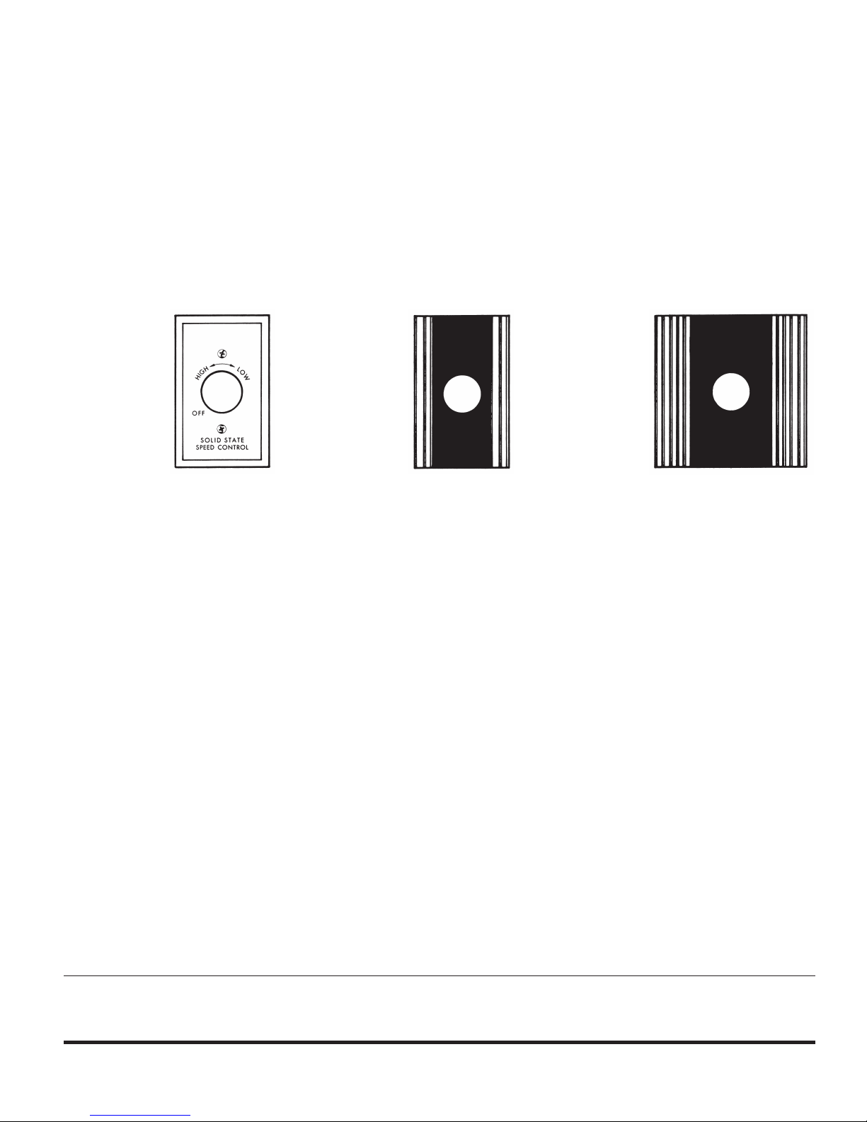
Models 12003 Models 12008
27708
3 Amps
Description
Leading Edge solid state adjustable speed controls are
engineered and designed specifically for use with
Leading Edge commercial/industrial ceiling fans.
Controls provide adjustable speed operation at any point
between minimum and maximum fan speeds. All models
have a hard plastic backing to protect components and
circuit board and dial on/off switch. 3 Amp control Model
features brushed aluminum wall plate. 8 and 12 Amp controls feature a finned aluminum heat sink plate, wire
brushed gold finish and black trim. All models are UL
Listed.
Models 12012
8 Amps 12 Amps
General Safety Information
WARNING: DISCONNECT POWER SUPPLY BEFORE
WIRING CONNECTIONS ARE MADE TO PREVENT
POSSIBLE ELECTRICAL SHOCK OR DAMAGE TO
EQUIPMENT.
WARNING: READ AND FOLLOW INSTRUCTIONS
CAREFULLY. FAILURE TO COMPLY WITH INSTRUCTIONS COULD RESULT IN FIRE, ELECTRICAL
SHOCK, INJURY TO PERSONS, AND/OR DAMAGE TO
EQUIPMENT.
1. All wiring should conform to the National Electrical
Code and local regulations.
2. Do not mount in an area which will allow the control
to come in contact with moisture.
3. Make certain the entire installation is grounded as a
precaution against possible electrical shock.
4. Do not exceed maximum amperage rating of the
control as overloading can result in damage to
ceiling fan and control.
SPECIFICATIONS AND
RECOMMENDED CONTROL
CALCULATIONS PER FAN MODEL
MODEL
NUMBER
12003
12008
12012
27708
ECR 40490
VOLTS
120
120
120
277
AMPS
3
8
12
8
CONTROLS
36"/120
36201A
UNITS
3
10
12
CONTROLS
56"/120
56001A; 56001BA;
56001LCA;
CONTROLS
48"/120
48201A; 48201BA
UNITS
2
6
10
12/16 5200-2405-00
56011A; 56111A;
56301RDP;
56101A; 56201A
UNITS
2
6
10
CONTROLS
56"/220/277
56007A
UNITS
6
CONTROLS
60"/120
60001A;
60111A;
60101A
60011A
UNITS
1
4
8
3
Page 2

Installation
1. Turn power off at circuit breaker panel or fuse box.
2. Mount control to standard single gang wall box.
3. Run conduit between the wall box, power source, and
the fan units being controlled. Leave approximately
six inches of wire in the box for connections
(See Figure 1).
4. Make wiring connections as shown in Figure 2.
Connect one hot line from the supply to one black of
the control. Connect the second black of the control
to the black from the fan motor. Connect green ground
wire to wall box. Make sure that the wire strands are
straight and attach the wire leads of the control to the
circuit wires by twisting them together. Twist a wire nut
onto each connection.
5. Check all connections for tightness; leave no exposed
copper conductor.
6. Position connections in box, leaving room for control.
7. Install speed control in wall box using screws supplied.
8. Attach control knob by pressing onto shaft firmly.
9. Restore power at circuit breaker panel or fuse box.
NOTE: When any solid state speed control is used, a
humming noise will be present in the fan on low speed.
This hum in no way affects the operation of the fan and is
acceptable in most commercial/industrial installations.
Operation
3 AMP MODELS
To turn control “on,” turn knob clockwise until a “click” is
heard. To reduce fan speed, continue rotating knob clockwise to desired speed setting.
8 AND 12 AMP MODELS
To turn control “on,” turn knob clockwise until a “click” is
heard. To increase fan speed, continue rotating knob
clockwise to desired speed setting.
Figure 2 - Wiring Diagram
Figure 1 - Mounting Illustration
LIMITED WARRANTY
All products manufactured by Marley Engineered Products are warranted against defects in workmanship and materials for two years from date of installation. This warranty
does not apply to damage from accident, misuse, or alteration; nor where the connected voltage is more than 5% above the nameplate voltage; nor to equipment improperly installed or wired or maintained in violation of the product’s installation instructions. All claims for warranty work must be accompanied by proof of the date of installation.
The customer shall be responsible for all costs incurred in the removal or reinstallation of products, including labor costs, and shipping costs incurred to return products to
Marley Engineered Products Service Center. Within the limitations of this warranty, inoperative units should be returned to the nearest Marley authorized service center or
the Marley Engineered Products Service Center, and we will repair or replace, at our option, at no charge to you with return freight paid by Marley. It is agreed that such repair
or replacement is the exclusive remedy available from Marley Engineered Products.
THE ABOVE WARRANTIES ARE IN LIEU OF ALL OTHER WARRANTIES EXPRESSED OR IMPLIED, AND ALL IMPLIED WARRANTIES OF MERCHANTABILITY AND
FITNESS FOR A PARTICULAR PURPOSE WHICH EXCEED THE AFORESAID EXPRESSED WARRANTIES ARE HEREBY DISCLAIMED AND EXCLUDED FROM THIS
AGREEMENT. MARLEY ENGINEERED PRODUCTS SHALL NOT BE LIABLE FOR CONSEQUENTIAL DAMAGES ARISING WITH RESPECT TO THE
PRODUCT, WHETHER BASED UPON NEGLIGENCE, TORT, STRICT LIABILITY, OR CONTRACT.
Some states do not allow the exclusion or limitation of incidental or consequential damages, so the above exclusion or limitation may not apply to you. This warranty gives
you specific legal rights, and you may also have other rights which vary from state to state.
For the address of your nearest authorized service center, contact Marley Engineered Products in Bennettsville, SC, at 1-800-642-4328. Merchandise returned to the factory
must be accompanied by a return authorization and service identification tag, both available from Marley Engineered Products. When requesting return authorization, include
all catalog numbers shown on the products.
HOW TO OBTAIN WARRANTY SERVICE AND
WARRANTY PARTS PLUS GENERAL INFORMATION
1. Warranty Service or Parts 1-800-642-4328
2. Purchase Replacement Parts 1-800-654-3545
3. General Product Information www.marleymep.com
Note: When obtaining service always have the following:
1. Model number of the product
2. Date of manufacture
3. Part number or description
ECR 40490
12/16 5200-2405-003
470 Beauty Spot Rd. East
Bennettsville, SC 29512 USA
 Loading...