

Page 1
Marks USA • www.marksusa.com • 631-225-5400 • 800-526-0233 • Fax: 631-225-6136 • © 2008, Marks USA Page 1
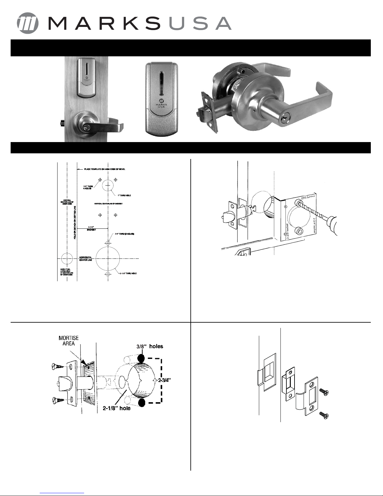
Figure 4
Figure 2
Figure 1
Figure 3
DOOR PREPARATION:
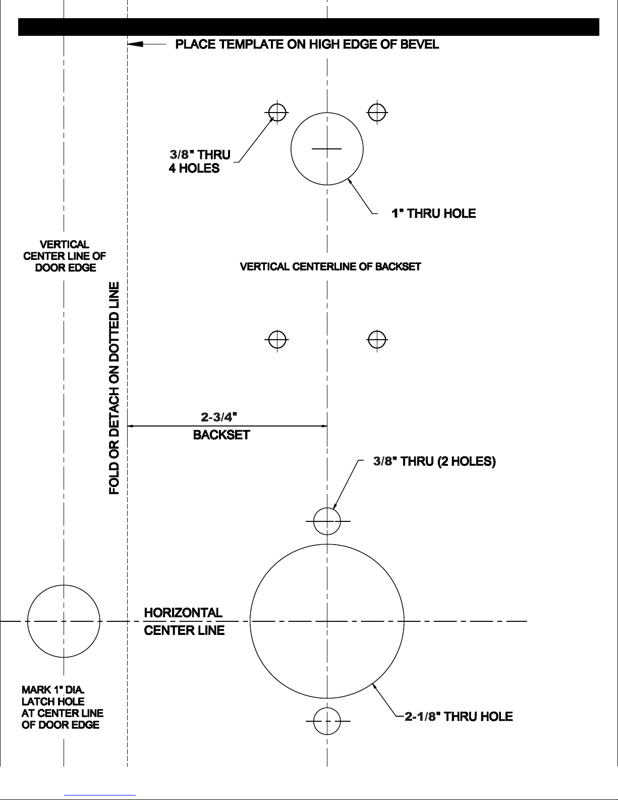
1. Fold and apply template to high edge of door at desired height from floor.
2. Mark hole centers on door and door edge.
3. Drill 3/8" thru-bolt holes first, then drill 2-1/8" hole.
INSTALL STRIKE:
1. Align strike with latch.
2. Trace strike outline on door jamb.
3. Mortise jamb and install strike and dust box.
INSTALL LATCH:
1. Drill 1" diameter hole for latch. Mortise for latch front. Insert latch and fasten with
two screws.
NOTE:
It is important that both 1" and 2-1/8" holes be on the same horizontal center line.
HOLLOW METAL DOORS:
1. Must have horizontal and vertical lock and latch support provided by door
manufacturer
2. If 2-1/8" hole exists, use optional Marks J295 Installation Tool to ensure
accurate drilling of 5/16" thru-bolt holes.
3. For best results, align the J295 Installation Tool to door and clamp to door
before drilling.
365 Bayview Ave., Amityville, NY 11701
631-225-5400 • 1-800-526-0233 • Fax 631-225-6136
www.marksusa.com
175 Biometric Installation Instructions
®
Door Preparation
Page 2
Marks USA • www.marksusa.com • 631-225-5400 • 800-526-0233 • Fax: 631-225-6136 • © 2008, Marks USA
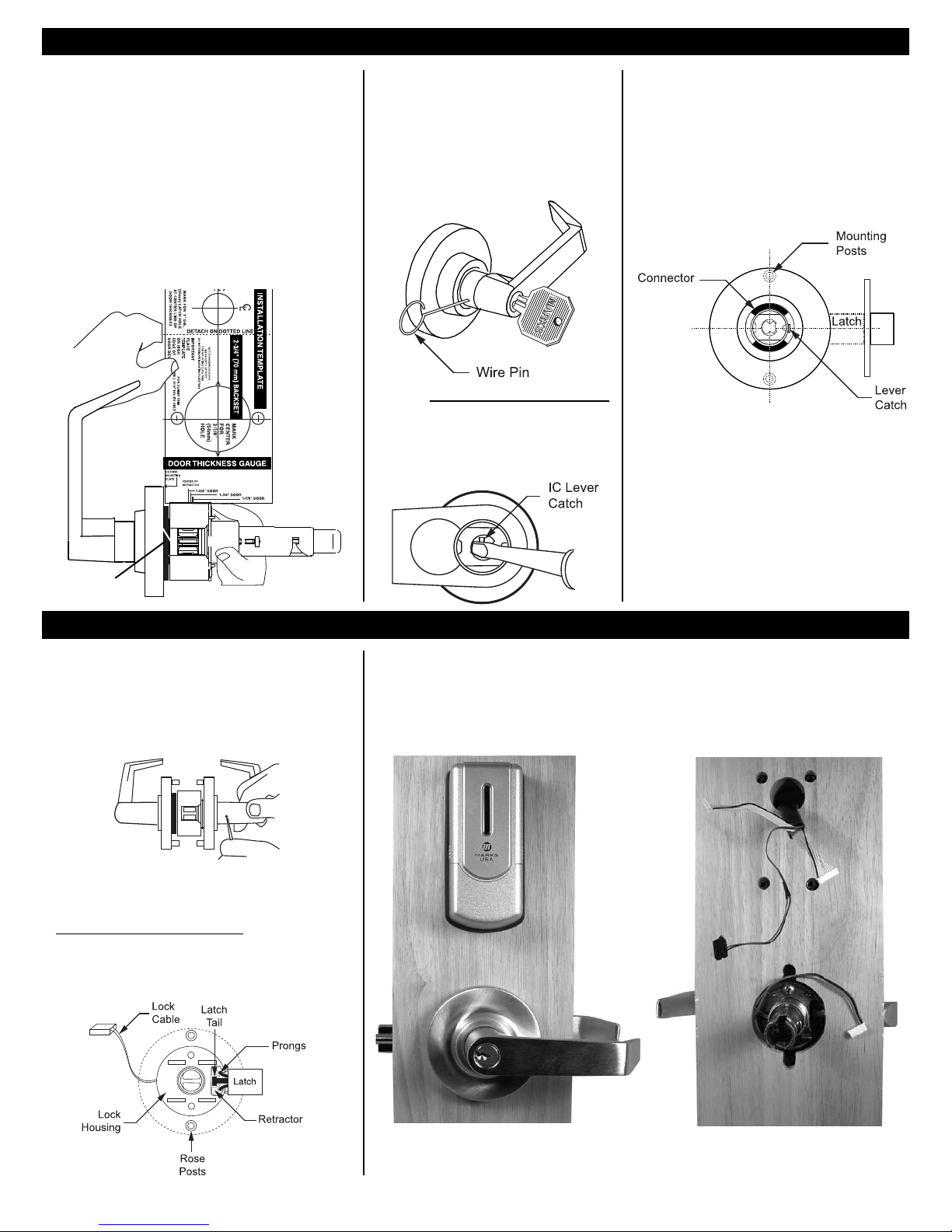
Figure 5 Figure 6
Figure 7
PREPARE LOCK:
1. Remove inside lever. Depress the lever catch with wire pin
through the small hole in the rose/lever and pull lever off the tube.
2. Depress lever catch again and remove the inside rose assembly.
INSTALL LOCK:
1. Push lock through 2-1/8" hole from the outside, so that retractor
engages latch tail and both prongs as shown below.
2. Prongs must engage inside lock housing.
3. Align outside rose so rose posts enter thru-bolt holes in door.
4. Check from inside of door to see if latch is properly engaged.
5. Bring lock cable to inside of door.
CONVENTIONAL CYLINDER
1. Turn key in cylinder 45° in either direction.
2. Depress outside lever catch with wire pin
through small hole in rose/lever and pull
lever off tube.
Door Thickness Adjustment
Installing The Lock Installing the Biometric Fingerprint Reader
Reinstalling Outside Lever
IC CORE CYLINDER
A. With IC core removed, use screwdriver inside
lever to depress lever latch.
B. Pull off lever.
Figure 8
NOTE: If lock is not in door, mounting posts must be on
vertical center line.
1. Align lever catch to face latch front.
2. Turn key in cylinder 45
° in either direction.
3. Slide lever on tube until it stops at the lever catch.
4. Slightly wiggle and push until lever engages lever
catch & connector.
Split Spacer
1. Locks are factory assembled with a ring for 1-3/4" thick
door.
2. Before installation, use door thickness gauge on template as
shown below, to check lock chassis position. Center of latch
retractor should align with mark on gauge for appropriate door
thickness.
If chassis is not on center, remove outside lever, screw chassis
in or out to align with mark. Check that lever engages lever
catch before installation.
3. Reinstall outside lever.
To Adjust For Other Door Thickness:
Remove outside lever.
Figure 9
INSTALL BIOMETRIC FINGERPRINT READER:
1. Insert outside fingerprint reader and lock through the mounting holes with their cables extending to inside of door.
Figure 10
Page 2
Page 3
Marks USA • www.marksusa.com • 631-225-5400 • 800-526-0233 • Fax: 631-225-6136 • © 2008, Marks USA Page 3
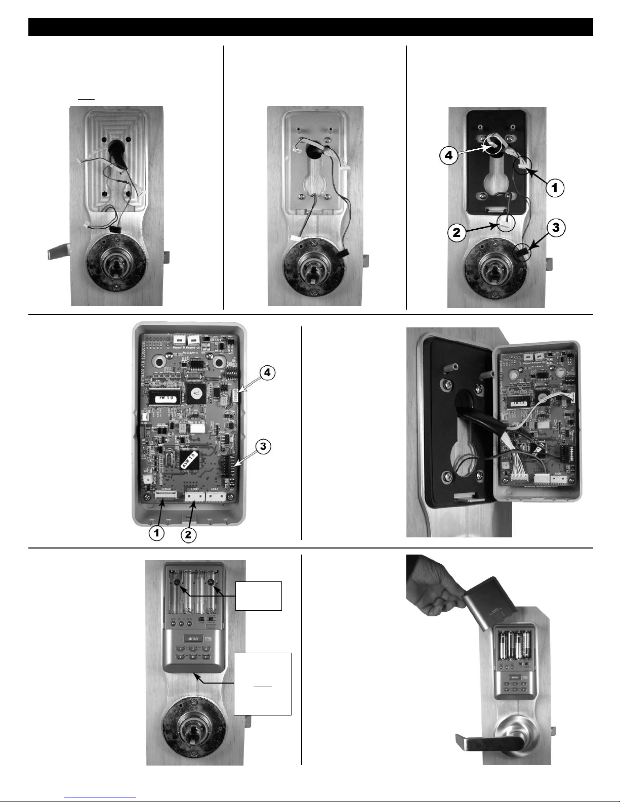
Figure 11 Figure 12
Installing the Biometric Fingerprint Reader
Figure 13
1. Place inside gasket over the support plate. Make sure
all cables come through the opening in the gasket.
Follow numbers for cable connections as you will see
in step 14.
1. Place Inside back plate over lock, with all cables coming
through the opening in the back plate.
2. Install inside rose on lock, over back plate, and fasten to
outside rose lightly with its two mounting screws.
Figure 14
1. Attach inside support plate to outside fingerprint reader
with four screws. Make sure all cables come through
the opening in the support plate.
1. Attach all cables to inside
module as shown.
Figure 15
1. When finished,
the cable connections
should be connected
as shown.
Figure 16
1. Install inside module onto
support plate with two screws
inside battery compartment,
and one screw at the bottom
of the module.
2. Tighten the two rose screws.
3. Snap on inside rose cover.
Make sure bumps on cover
align with dimples in rose.
2 Screws are
located here
1 screw is
located here
under
the bottom
of the unit
Figure 17
1. Install 4 “AA” batteries
and battery cover.
You are now ready
to program the lock.
Page 4
I-175 BIO 10.2008
Marks USA • www.marksusa.com • 631-225-5400 • 800-526-0233 • Fax: 631-225-6136 • © 2008, Marks USAPage 4
INSTALLATION TEMPLATE
 Loading...