

Marksman X4 Installation Manual

Installation
Manual
Model: X4
This device complies with part 15 of the FCC rules. Operation is subject to the following two conditions:
(1) This device may not cause harmful interference; and
(2) This device must accept any interference received, including interference that may cause undesired operation.
Note: The manufacturer is not responsible for any radio or TV interference caused by unauthorized modifications to this
equipment. Such modifications could void the user’s authority to operate the equipment.
For Technical Assistance, please call (800) 638-3600,
or visit www.magnadyne.com
Component Installation . . . . . . . . . . . . . . . . . . . . . . . . . . . . . . . . . . . . . . . . . . . . . . . . . . . . . . . . . . . . . . . . 2
Wiring Harness Quick Reference . . . . . . . . . . . . . . . . . . . . . . . . . . . . . . . . . . . . . . . . . . . . . . . . . . . . . . . . . 3
Wiring
White 10-Pin Main Harness . . . . . . . . . . . . . . . . . . . . . . . . . . . . . . . . . . . . . . . . . . . . . . . . . . . . . . . . . . . 4-5
White 5-Pin Power Harness. . . . . . . . . . . . . . . . . . . . . . . . . . . . . . . . . . . . . . . . . . . . . . . . . . . . . . . . . . . 6
Black 3-Pin Door Lock Harness . . . . . . . . . . . . . . . . . . . . . . . . . . . . . . . . . . . . . . . . . . . . . . . . . . . . . . . . 7-9
Plug-In Ports . . . . . . . . . . . . . . . . . . . . . . . . . . . . . . . . . . . . . . . . . . . . . . . . . . . . . . . . . . . . . . . . . . . . . . . . 10-12
Optional Accessory Connections . . . . . . . . . . . . . . . . . . . . . . . . . . . . . . . . . . . . . . . . . . . . . . . . . . . . . . . . . 13
Programming the Transmitter . . . . . . . . . . . . . . . . . . . . . . . . . . . . . . . . . . . . . . . . . . . . . . . . . . . . . . . . . . . 14
Alarm Feature Programming . . . . . . . . . . . . . . . . . . . . . . . . . . . . . . . . . . . . . . . . . . . . . . . . . . . . . . . . . . . . 14-17
Shock Sensor Testing and Adjustment . . . . . . . . . . . . . . . . . . . . . . . . . . . . . . . . . . . . . . . . . . . . . . . . . . . . 18
Return to Default Settings . . . . . . . . . . . . . . . . . . . . . . . . . . . . . . . . . . . . . . . . . . . . . . . . . . . . . . . . . . . . . . 19
Wiring Diagram . . . . . . . . . . . . . . . . . . . . . . . . . . . . . . . . . . . . . . . . . . . . . . . . . . . . . . . . . . . . . . . . . . . . . . 20
Mounting the Control Module:
Find a suitable location to secure the alarm control module within the passenger’s compartment of the vehicle.
Never mount the alarm control module in the engine compartment or in the trunk. In addition, never mount the
alarm control module in the direct path of the heater. Secure the alarm control module by using wire ties or drill
two 1/8" holes and secure the module to the frame of the vehicle with the screws provided.
Installing Hood / Trunk Pin Switches:
Provided with the alarm kit is one pin switch and one mounting bracket. To install the switch either in the truck
or under the hood, find a suitable location where the switch will make contact with the hood or trunk lid and will
not get wet. Use the bracket provided or drill a 1/4" hole in the desired location.
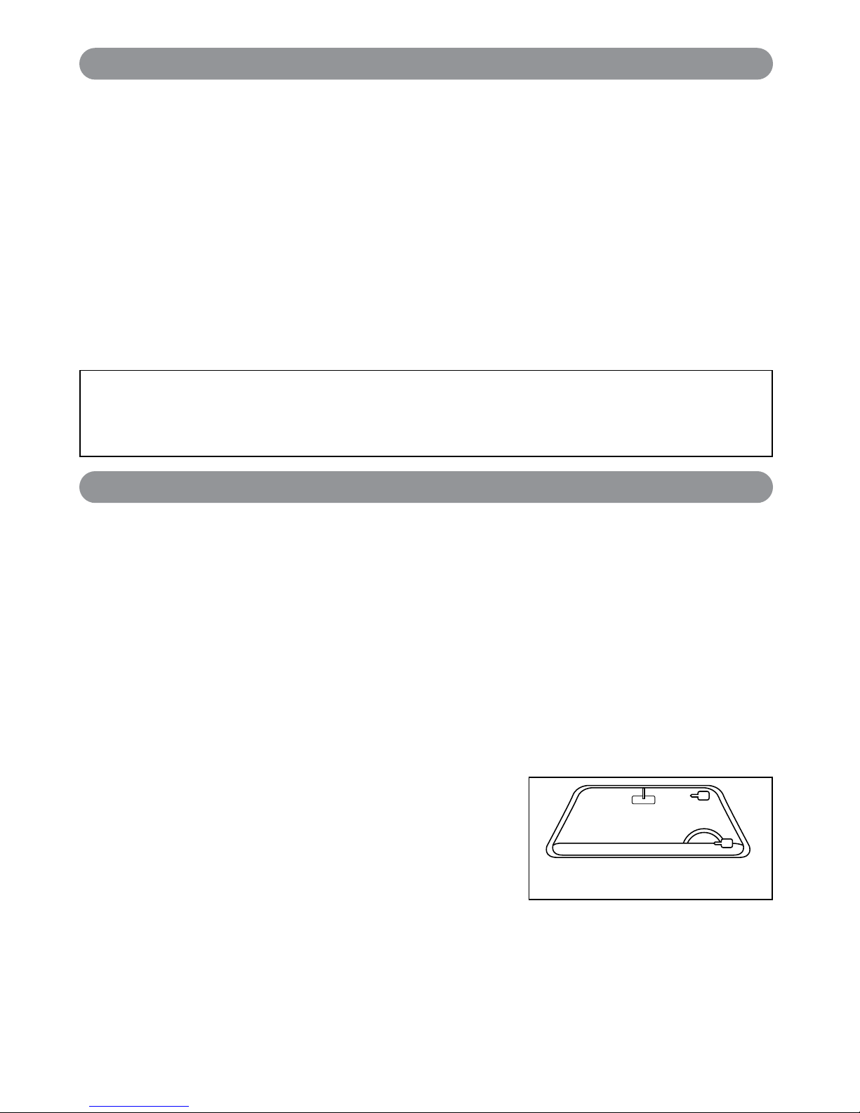
Windshield Transceiver/Antenna
The combination windshield transceiver/antenna mounts on the windshield (inside vehicle). We suggest you
mount the transceiver/antenna on the lower left-hand side of the windshield.
Warning! Do not mount the Windshield Transceiver/Antenna in such a manner that it obstructs the driver’s view.
• The transceiver/antenna can be mounted vertical or horizontal.
1. Remove the protective tape backing.
2. Carefully align the receiver/antenna and apply to windshield.
3. Route the black connecting cable behind the trim and connect
to transceiver/antenna.
4. Connect the other end to the control module.
Valet Switch
Select a mounting location for the switch that is easily accessible to the driver of the vehicle. The switch does
not have to be concealed. However, concealing the switch is always recommended, as this provides an even
higher level of security to the vehicle. Mount the valet switch in a hidden but accessible location. Route the valet
switch wires to the control module.
LED Status Indicator
The LED status indicator should be mounted in a highly visible area. Leave at least 6mm of space behind the
mounting location for LED housing. Once a suitable location is chosen, drill a 1/4" hole. Run the LED wires
through the hole then press the 2-pin LED housing into the place. Route the LED wires to the control module.
Warning! Do not plug the 10-pin or 5-pin wire harness into the alarm control module before you begin
installing the alarm. The wire harnesses must be plugged into the alarm control module after all
connections are made. Failure to follow this procedure could cause some confusion with transmitter
operation and or alarm function operation.
Table of Contents
Component Installation
2
Mount the antenna horizontally
for best reception.
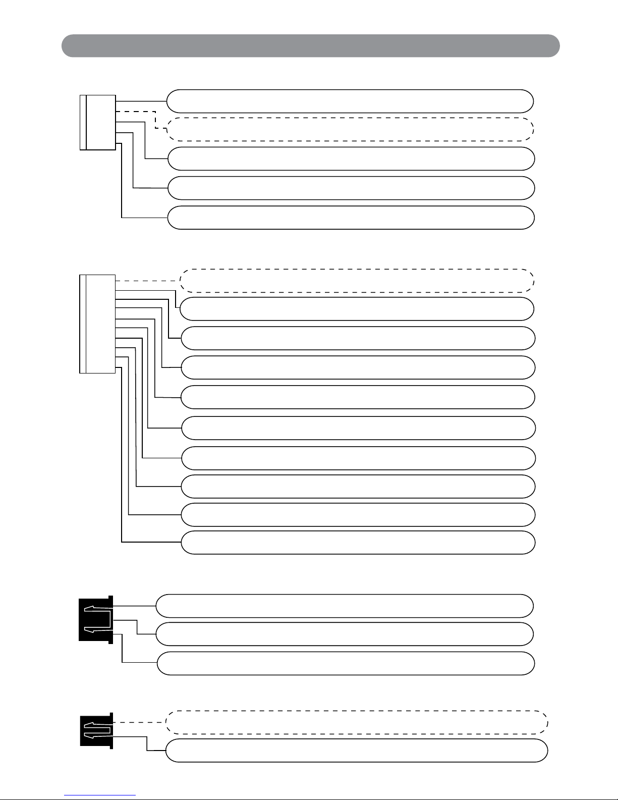
HC2 5 Pin Power Harness
Black/White (-) Dome Light Supervision Output
Black Chassis Ground
Yellow +12VDC Ignition Input
Open Provides +12VDC for Relay Connection
Red +12VDC Battery Input
HC4 10-Pin Main Harness
Open Provides +12VDC Relay Coil Power
Light Brown (-) Horn Output
Green (-) Common Door Pin Input
Violet (+) Common Door Pin Input
Blue (-) Hood / Trunk / Auxiliary Trigger Input
Red/White
(-) 300mA Programmable Channel 3 (Trunk) Output
White (+/-) Parking Light Relay Output
Brown (+) Siren Output
Violet/Black (-) 200mA Programmable Channel 4 Ouptut
White/Red (+/-) Parking Light Relay Input
H1 2-Pin Starter Disable Harness
Open Provides +12VDC Ignition Key On Power
Orange Provides “Ground-When-Armed” Output
HC3 3-Pin Door Lock Harness
Green (-) Lock
Light Blue Programmable Output (2nd Unlock Default)
Blue (-) Unlock
3
Wiring Harness Quick Reference
The main wire harness contains 9 wires which all have a specific purpose. Follow the wiring recommendations
enclosed for each wire. Wires not used should be released from the harness connector or taped off to prevent
accidental shorting.
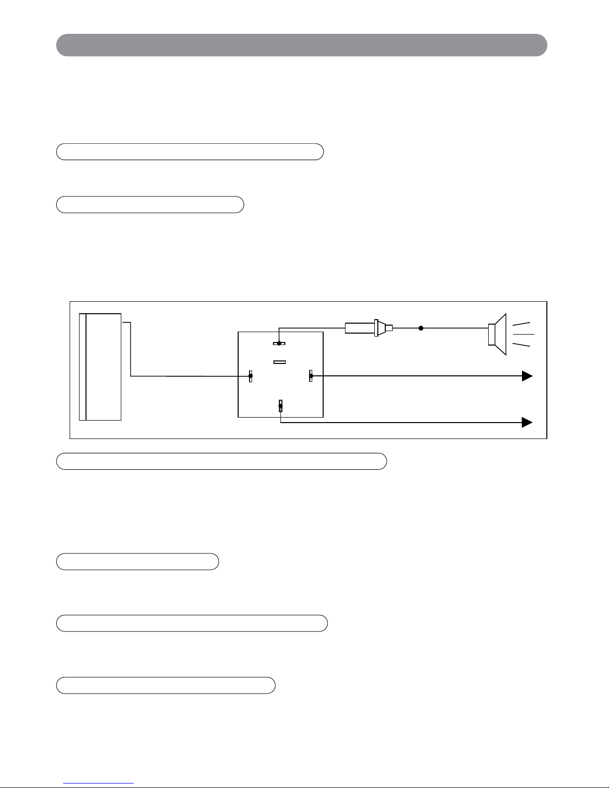
The Light Brown wire is a pulsed ground output designed to activate the vehicle’s existing car horn system in
place of or in addition to a siren sounding device. Connect the Light Brown wire to the negative trigger wire on
the vehicle’s horn relay.
WARNING! Maximum output of this wire is 300mA. Horn systems requiring positive voltage or more than
300mA to trigger the horn relay will require an additional relay to increase current capabilities.
HC4: White 10-Pin Main Harness
87
87a
86
85
30
Light Brown Wire
To +12V
To Horn
+12V or Ground Depending
on System Requirements
Fuse
Wiring
4
Vacant Socket: Provides +12VDC Relay Coil Power
For use with ALA-RPT relay pack only. See Optional Accessory Connection for proper wiring.
Light Brown Wire: (-) Horn Output
Violet/Black Wire: (-) 200mA Programmable Channel 4 Output
(See Alarm Feature Programming Group 3) (Factory default setting is pulse ground) This wire is programmable
to provide a pulsed output or a programmed timer output. You may program the output to send ground signal
for 15 seconds, 30 seconds or have output for as long as you are pressing the control button on the
transmitter. This output can also be programmed for a latched output that is turned off by the ignition key.
Follow the programming procedures to adjust the output type to fit your requirement.
Brown Wire: (-) Siren Output
Connect the brown wire to the positive wire from a siren. Ground the remaining wire from the siren for proper
operation.
Blue Wire: (-) Hood / Trunk / Auxiliary Trigger Input
The blue wire is an instant grounding trigger input for optional hood/trunk grounded pin switches or any
electronic sensor.
Green Wire: (-) Common Door Pin Input
The green wire connects to the common wire of the vehicle that switches on the dome light. Normally this wire is
located at one of the door jamb switches. For some vehicles it may be necessary to connect the green wire directly
to the switched turn on wire at the dome light. The green wire connects to negative switched circuits only
.
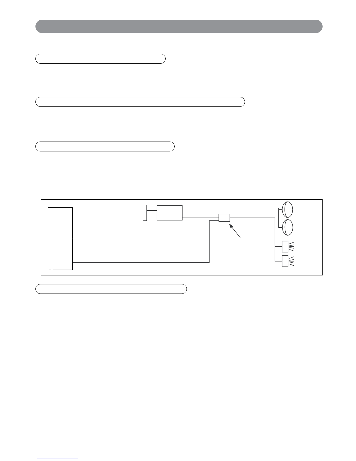
HC4: White 10-Pin Main Harness (continued)
Parking
Lights
Only
Piggyback
Connection
Headlight Switch
White Wire
Wiring (continued)
5
Violet Wire: (+) Common Door Pin Input
The violet wire connects to the common wire of the vehicle that switches on the dome light. Normally this wire is
located at one of the door jamb switches. For some vehicles it may be necessary to connect the violet wire directly
to the switched turn on wire at the dome light. The violet wire connects to positive switched circuits only.
Red/White Wire: (-) 300mA Programmable Channel 3 (Trunk) Output
(See Alarm Feature Programming Group 3) (Factory default setting on 1 second pulse output for trunk release)
The red/white wire is typically used to release the power trunk by remote. This wire can also be programmed for
15 second timer output, 30 second timer output or output as long as you hold the transmitter button down.
White Wire: (+/-) Parking Light Relay Output
Connect the white wire to the parking light wire coming from the headlight switch. Do not connect the white
wire to the dashboard lighting dimmer switch – Damage to the dimmer will result. Use a volt meter to test the
connection point before connecting the white wire. While checking, rotate the dimmer switch to make sure you
do not have the dimmer lead. The limitation of the white wire is 10 Amp max. Do not exceed this limit or
damage to the alarm and parking light relay will result.
The white/red wire is the input to the flashing parking light relay. The connection of the white/red wire will
determine the output polarity of the flashing parking light relay. Connect the white/red wire to (+) battery to have
(+) output from the relay or connect the white/red wire to chassis ground to have ground output from the relay.
White/Red Wire: (+/-) Parking Light Relay Input
HC2: White 5-Pin Power Harness
6
Wiring (continued)
Black/White Wire: (-) Dome Light Supervision Output
The Black/White wire provides a low current (300mA) grounded output that can be used to activate the vehicle’s
interior lighting system when the security system is disarmed. In some vehicles, an additional relay may be
required for proper installation (See Optional Accessory Connection for proper wiring).
Vacant Socket: Provides +12VDC for Relay Connection
See Optional Accessory Connection for proper wiring.
Black Wire: Chassis Ground
This is main ground connection of the alarm module. Make this connection to a solid section of the vehicle
chasis. Do not connect this wire to any existing ground wires supplied by the factory wire loom, make the
connection to the vehicle’s chasis directly.
Yellow Wire: +12VDC Ignition Input
Connect the Yellow wire to a +12 volt wire that is switched on and off by the ignition key. The correct wire will
indicate +12 volts when the ignition key is in the on and start positions. Do not connect the yellow wire to the
“ACC” wire coming from the ignition switch.
Red Wire: +12VDC Battery Input
Connect the Red wire directly to the (+) battery post for best operation of the alarm system.
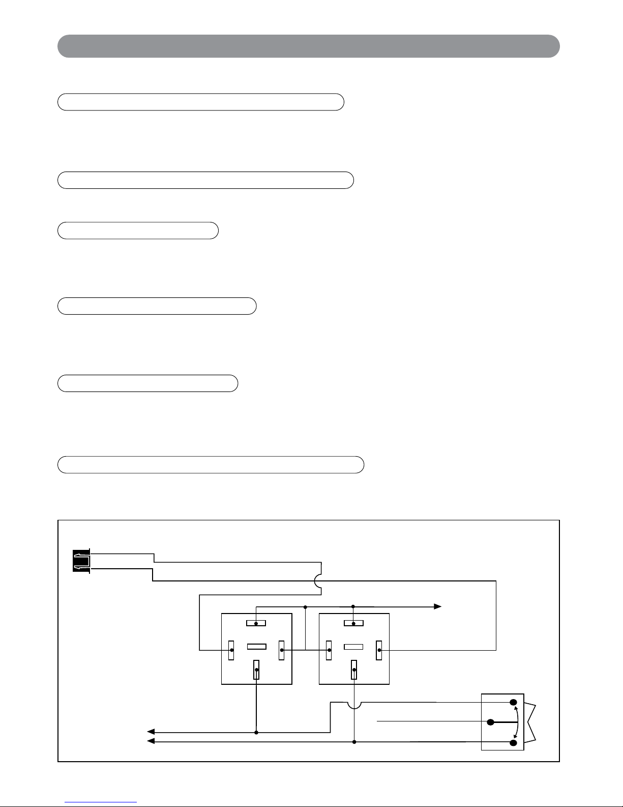
HC3: Black 3-Pin Door Lock Harness
3 Wire Positive Trigger Door Lock System
(+) Lock Out
+12 Volts Input
(+) Unlock Out
To Door Lock
Control Relays
Blue Wire: Connect to Unlock
Green Wire: Connect to Lock
Lock Control
Switch
Black 3-Pin
Mini Connector
87
87A
85
86
30
87
87A
85
86
30
To Fused +12v
If the door lock control system on the vehicle is (-) type, connect the Blue wire to the unlock wire from the door
lock switch .
Blue Wire: (-) Door Unlock
 Loading...