

Page 1

1
MCU-100N USER MANUAL
TEL: +82-31-776-0803~6
FAX: +82-31-776-0807
Web-page: www.pinmarking.com
E-mail: isaac@pinmarking.com
Page 2

2
INDEX
General information
Installation
FUNCTION and operation program
Handling of Keyboard
F1 (M_MANU) MODE
F2 (A_MARK) MODE
F3 (Edit) MODE
F4 (File) MODE
F5 (Setup) MODE
F6(Test) MODE
F7(Font & Plt Load) MODE
F8(Communication) MODE
Control to the marking machine by PC
Create PLT file by AUTO-CADR14
Maintenance
Appendix
How to use JS-1000 s/w
Page 3
3
Thank you for purchasing Jeil M-tech`s CNC DOT PIN Marking Machine
TO maximize the efficiency for operating CNC DOT PIN Marking machine, read the details in this manual.
If there are any problems not mentioned in this manual, please inquire us and we will answer you as soon
as possible. Also, If there are any suggestion regarding inconveniences or improvement, please inform us.
The products are constantly upgraded, and we assure you that it will help the equipment maintenance.
TEL
031-776-0803~6
FAX
031-776-0807
E-MAIL
isaac@pinmarking.com (Int`l Sales)
lji@pinmarking.com (Int`l Sales)
tech@pinmarking.com (Technical support)
WEB SITE
www.pinmarking.com
is Jeil-Mtech`s Trade name
The marking pin has a low sound level of less than”60db,”has acquired the patent and registration,
and has been produced since Jan 2000
Marksman is manufactured and confirmed by the Europe CE certification standards “security,
endurance, and electromagnetic wave standards, etc”
The warranty term is 1 year since the delivery date. After a year, the traveling expenses will be billed.
All components are applicable for warranty, with the exception of intentional or accidental defeats.
When a problem occurs during delieverly and installation by the dealer, immediately return
the products to the Dealer and get it checked.
Any problems resulting from intentional or accidental mistakes are not applicable for warranty.
.
- Modification date of manual : .02.04.2013
Page 4

4
MARKING HEAD
MK100-115 (Standard type) MK100-90J (Dust cover) MK073
MK-054 (Portable type) MK100-BS (Ball screw type)
MARKING CONTROLLER
MCU-100N(Built in the keyboard) MCU-200BN
MARKING PIN
LP-06 LP-10 PLP-10 PH-16
Page 5

5
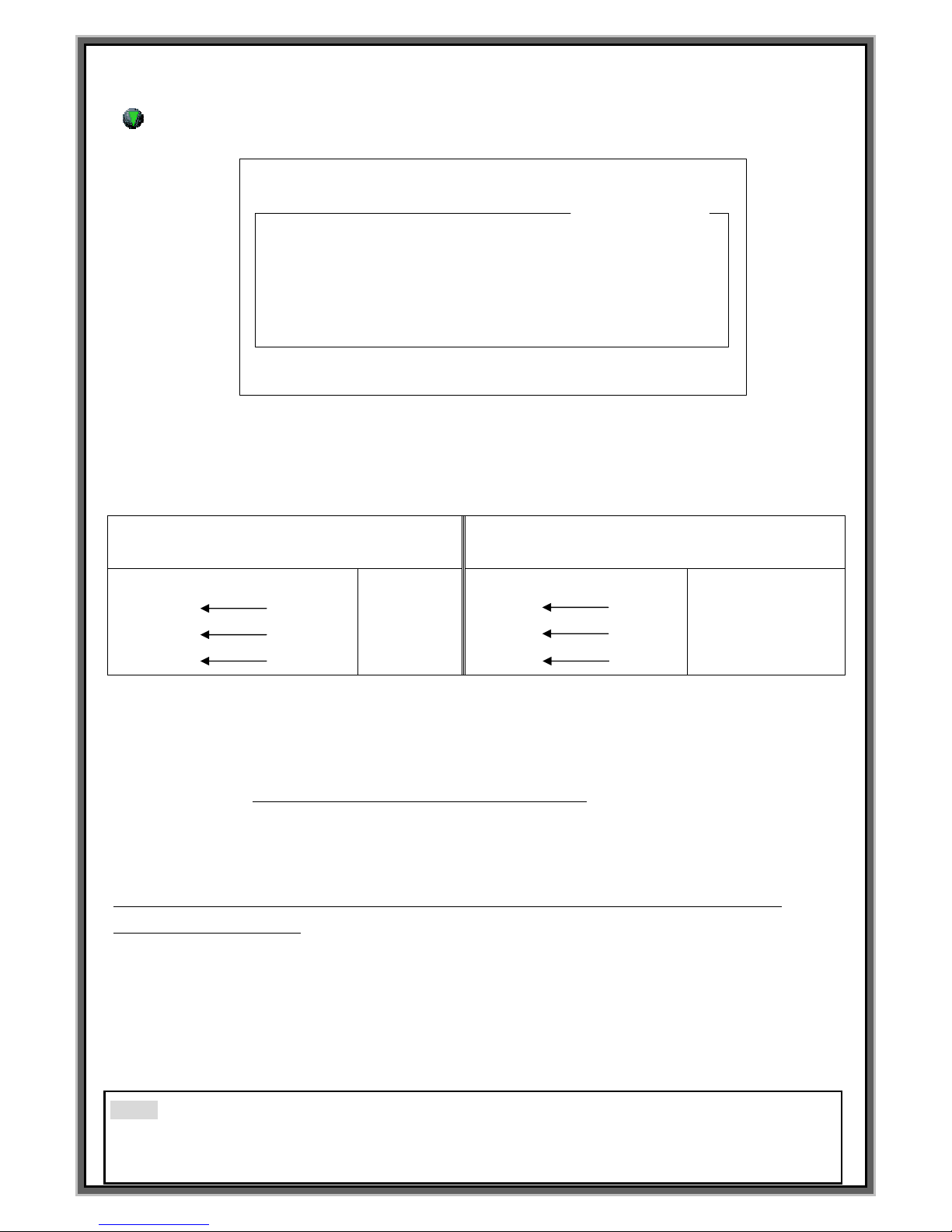
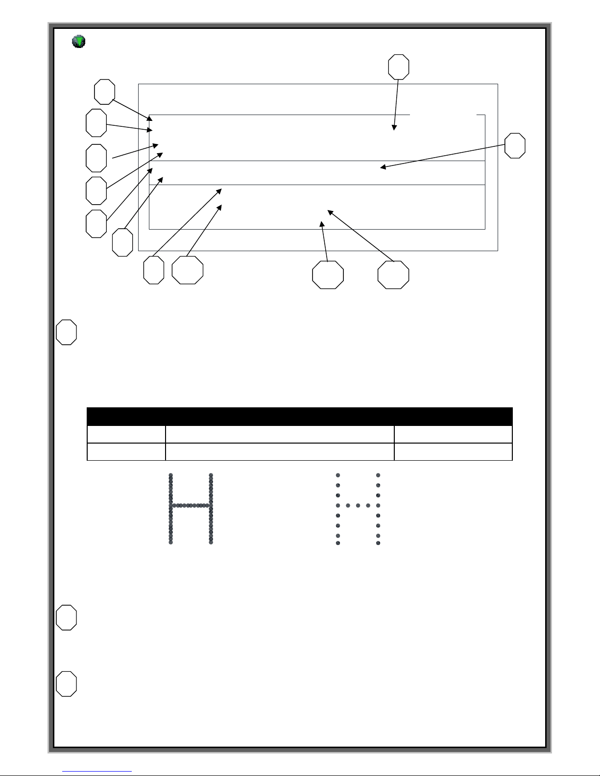
Composition of Marking system
Composition and application of CNC Marking Machine
Jeil Mtech has got certificate that ISO 9001, 14001, CE Mark and
Many kinds of domestic Certificate.
?
메인 커넥터
I/O 포트
옵션보드
RS-232 포트
메인 전원커넥터
110~220 Free Volt
USB 포트
?
Marksman
MCU-100N
KE Y B OAR D
www.pinmarking.com
Display
옵션보드
RS-232 포트
메인 전원커넥터
110~220 Free Volt
LCD 화면
메인 전원SW
+5V
READY
WORKING
END
ALRAM
+24V
상태지시등
SD카드 삽입구
마킹핀방식선택
키보드 수납함
스테핑 드라이버
고정나사 M3X4
LCD 화면 밝기 조정
USB 포트
Clamping screw
of Stepping
driver M3X4
Main power S/W
Keyboard drawer
Adjustment of brightness
for LCD
Option Board
Main power connector
Main Connector
I/O
USB
RS-232
Lamp
Pin selector
SD card slot
Page 6

6
installation
Matters to be attended to before installation
Main source of electricity: AC220Volt, 1ph, 3Ampare
Cable connection: All cables need to be installed by being connected fast without being bent
or twisted.
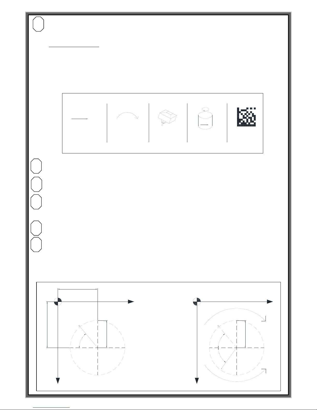
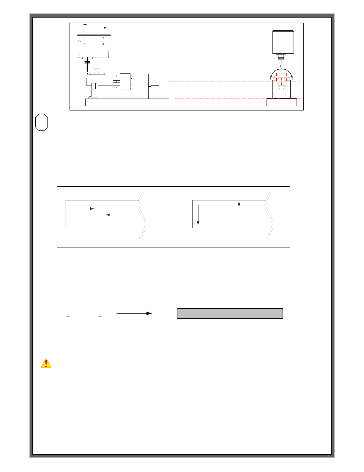
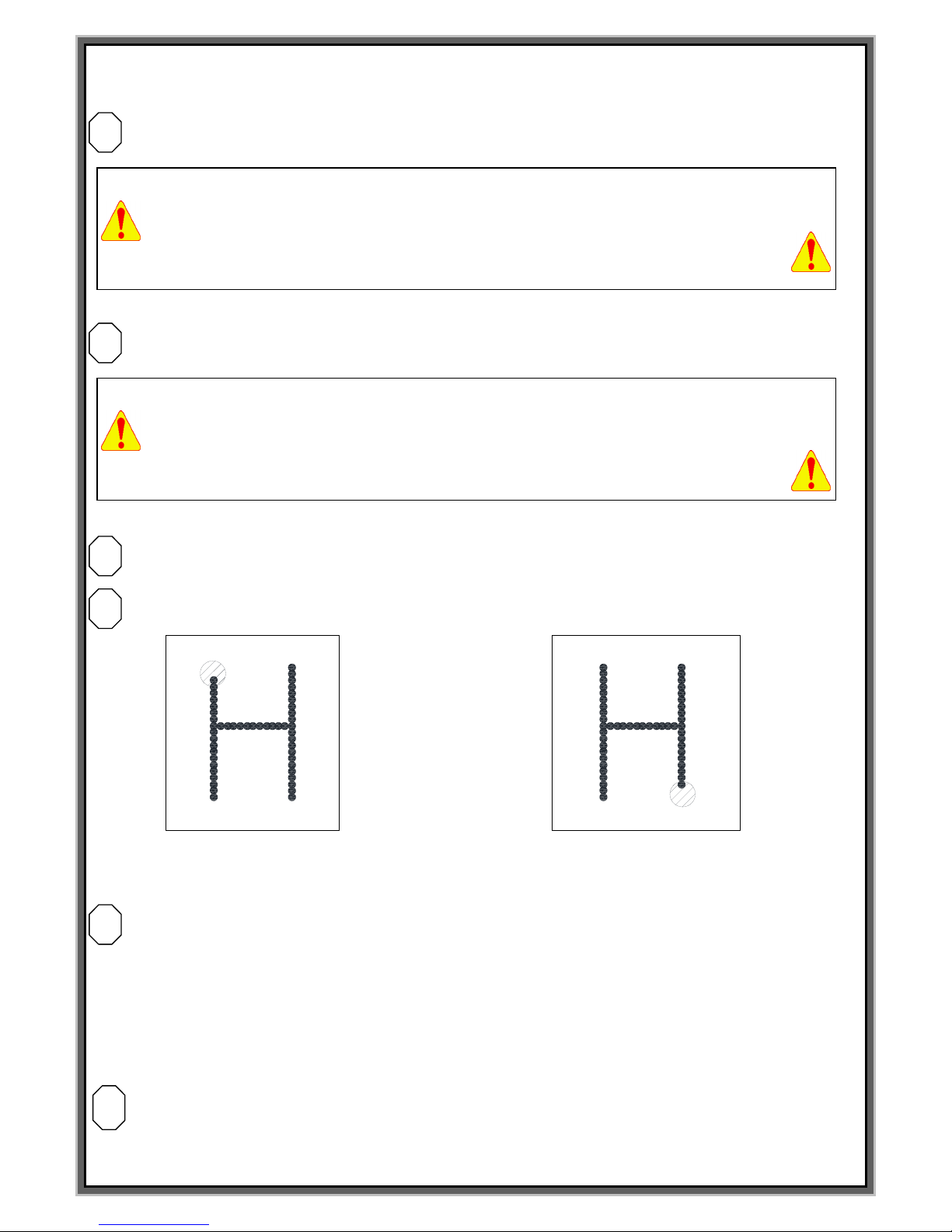
Installation of Marking Head
Installation should take place so that the distance between the Pin and the surface of work piece should be
3.5~4.5mm with a deviation of ±10mm.
Control marking quality :
The quality of the marking products differ according to marking distance and air pressure.
At the Parameter Setup of MCU`s F4 screen, you can control the transfer speed of the pin.
Also You can choose the thickness of the pin edge-
The ball type of marking pin is thick and deep. The sharp type of marking pin is thin and deep.
.
+ Marking depth will be deeper when the distance between marking pin and work piece is far
Refer to the drawing below to decide the installation location and the Pin interval.
X축
Y축
0점
ABCDEF
Marking Area
3~5mm 유지
소재
(References1) (References2)
#.Be able to reduce cycle time when marking position is close with 0 point
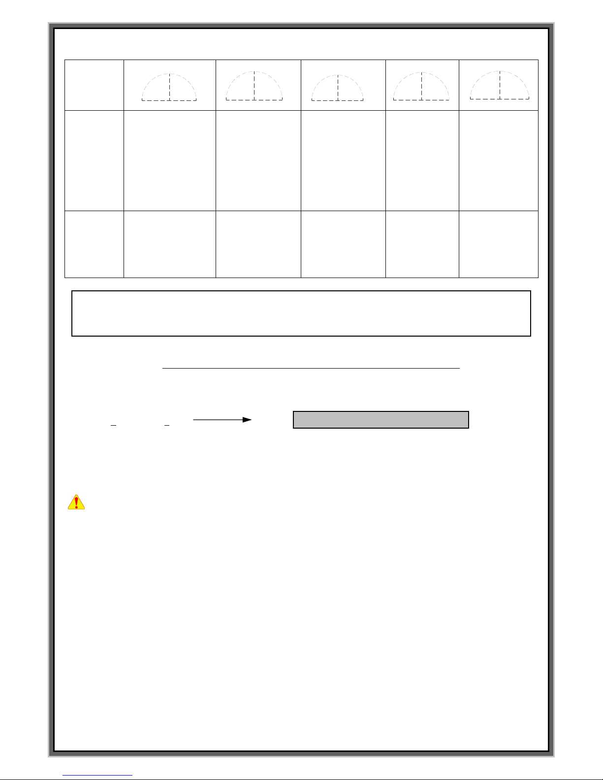
PH-16
LP-06
LP-10
PLP-10
Valid marking
distance
2 mm ~ 5 mm
4 mm ~ 12 mm
4 mm ~ 15 mm
4 mm ~ 15 mm
Appropriate
distance
3 mm
6 mm
6 mm
6 mm
Valid air pressure
4 ~ 5 Kg/cm2
2 ~ 3 Kg/cm2
2 ~ 3 Kg/cm2
2 ~ 3 Kg/cm2
Appropriate air
pressure
4 Kg/cm2
2.5 Kg/cm2
2.5 Kg/cm2
2.5 Kg/cm2
Keep the distance
3 to 5 mm
Workpiece
Page 7

7
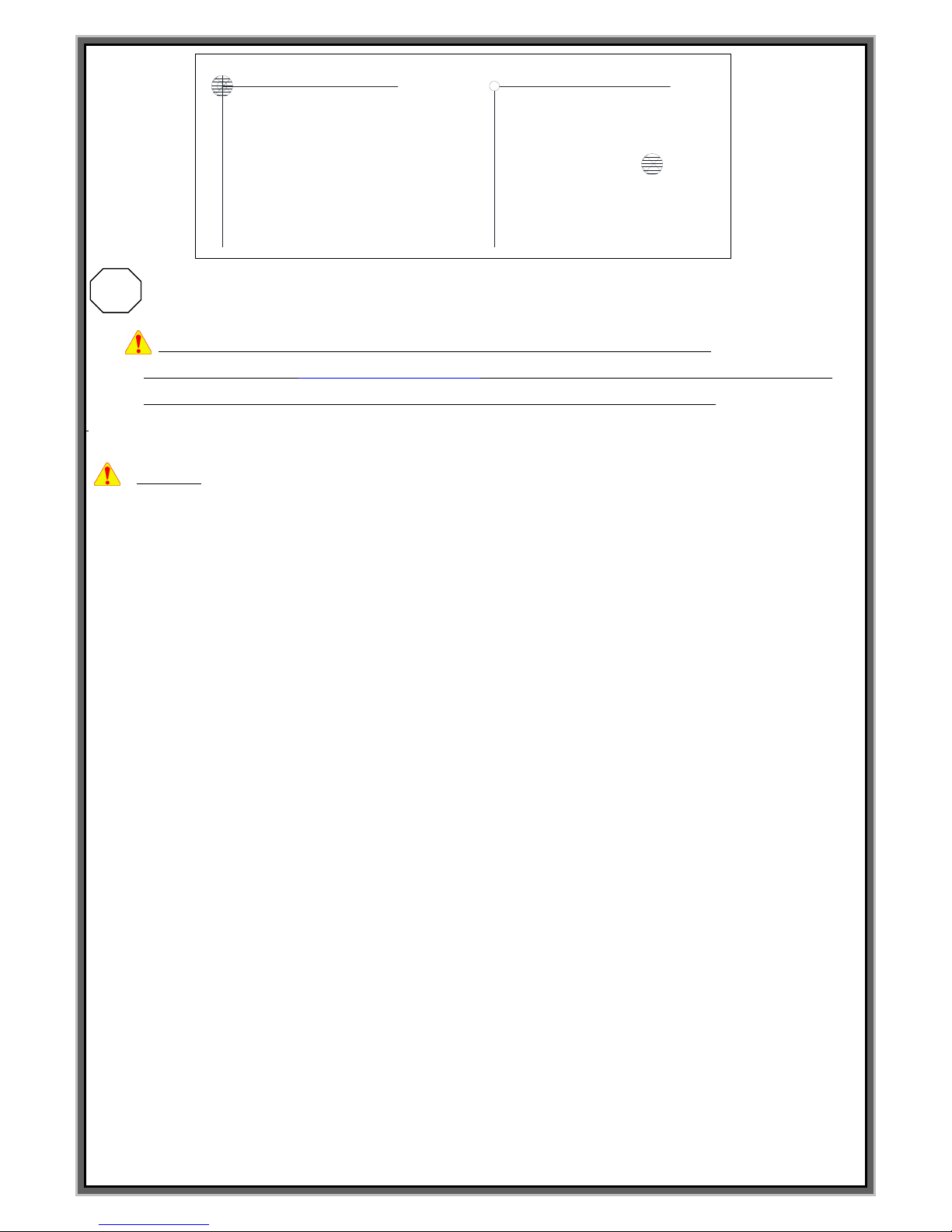
Puncher sound level
In general, the puncher sound increases when the board is thin and the clamp is not steadily attached.
Sound cover attached: 55db, with silencer: under 50db
Puncher with weighty substance in open space: 72db with silencer: 56db
Puncher with a board less than 2 t in open space: 87db with silencer: 68db
Soundproof cover for a board less than 2 t in open space: 65db, with silencer: 50db.
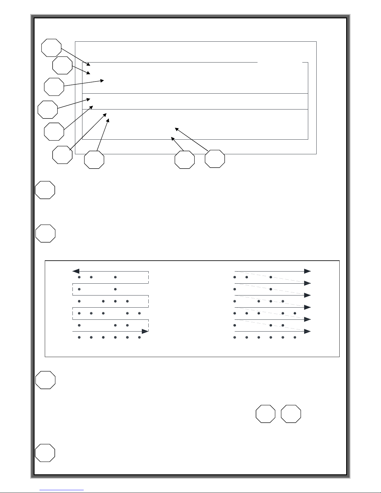
Please read the following before executing the program
<FUNCTION Keys>
F1: M_MENU (Manual marking mode) I
Can mark and modify the selected block. This function is not suitable on the Automation line
F2: A_MARK (Automatic marking mode)
Marking mode. Includes status window for the marking and produced amount of the block data for the
Puncher.
F3: EDIT (Editing mode)
Edit the marking contents such as font, font size, letter space, Lot number, operation method, and
Direction of the letters.
F4 : FILE (File mode)
Save the marking data and the value of parameter to the S/D card.
F5 : SETUP (Adjustment mode of parameter)
Control the speed of marking and motor. As well as you can designate the data of shift and
daily code
F6 : TEST (Test mode)
Can check the condition of stepping motor and sol. Valve on this mode. Also you can modify
the time, year, month and day.
F7 : LOAD (User font set up mode)
Can load USER font and Logo (.plt file) which is in SD card and JS-1000 on this mode.
F8 : COMM (Serial communication mode)
Can control the marking machine by external PC through RS-232 Cable .
F9 : SIMULATION (Simulation marking)
Can do simulation marking on (F1)M_MARK , (F2)A_MARK , (F8)COMM. You can use this function
when you set the marking location.
F10 : MARKING START
Can give Start signal on (F1)M_MARK , (F2)A_MARK , (F8)COMM.
F11 : RESET (Reset )
Can reset the controller by keyboard on (F1)M_MARK , (F2)A_MARK , (F8)COMM
For other keys,
ENTER : You must press “ENTER” after modify the data.
SPACE BAR : If press the Space bar on the Font and Type section, operation mode is converted.
Direction Key : Searching for the file on (F4)FILE or check the moving of the motor on (F6)TEST.
DELETE/INSERT : Check the condition of sol.valve on (F6)TEST mode.
Page 8

8
F1 MANUAL MARK MODE
Page 9

9
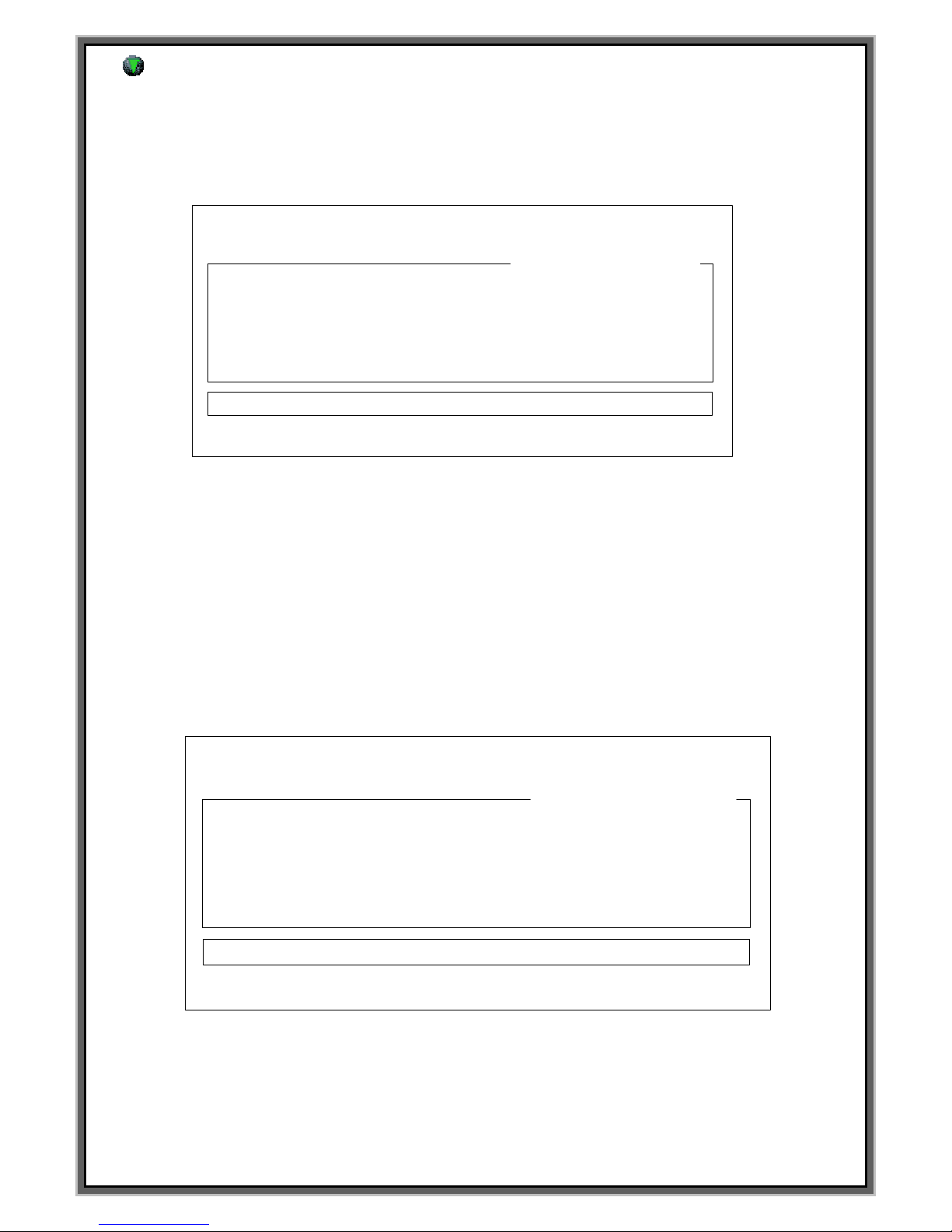
(F1)Screen : M_MENU (Manual marking)
F1 : M_MENU F2 : A_MARK F3 : EDIT F4 : FILE
F5 : SETUP F6 : TEST F7 : LOAD F8 : COMM
BLK NO. [ 000 ]
LN X : 0300 Y : 0300 A : 000
FNT : STD1 CH:030 PX:030 PAUSE : N
MARK_UP_TO[ 00000000 ] UNIT_NO[00001713]
Blk Nos. [000] [001] [002] [003] [004]
15:15:22 0.00 STATUS [ ]
[MANUAL MARK MODE]
BLK_COPY : CTRL_C BLK_MOVE : UP/DOWN
CURSOR_MOVE : ENTER SELECT : SPACE_BAR
F9 : SIMULATION F10 : MARK F11 : HOME
F1 screen is the mode of simple manual marking. In case of manual marking, it can be done only
this screen. (But it can be done on the F8 mode when it is the marking using RS-232 Communication.)
IF you give the signal to the I/O on the F1, malfunctioned can be happened.(External control Malfunction)
BLK NO[000] : Block no. of the marking data
MARK UP TO: This function allows you to set a number of how many pieces of your product to be marked.
If you set the number like [00000100] to MARK_UP_TO,
when marked quantity reached this number, the system will be stopped automatically.
**Caution – This valve must be “0000000” on automation mode.**
UNIT NO : Indicate the work quantity until now.
Blk Nos. : Marking in order. Can change the marking order after you moves the cursor to Blk Nos.
15:15:22 : Indicate the present time.
0.00 : The Cycle time of previous marking. (Unit : sec)
STATUS : Indicate the status of marking machine
[ BLOCK ] : In case of marking using PLC START
[ MARKING ] : In case of marking by common START
[ END RUN ] : In case marking is done.
[ EMER STOP ] : When it gets the signal “Emergency stop” of PLC and error of the working
[ LIMIT ERROR ] : Limit error
[ UNIT END ] : When the specified marking quantity is done.
CUSOR_MOVE : ENTER : Moving the cursor and storage the data is the “Enter” on the keyboard.
SELECT :SPACE_BAR : Can change the mode of marking by Space_Bar on the keyboard
F9:SIMULATION : Simulation F10 :MARK : Marking F11:HOME: Return to home position
1
2
3
4
5
6
7
1
2
3
4
5
6
7
Page 10

10
F2 AUTO MARK MODE
Page 11

11
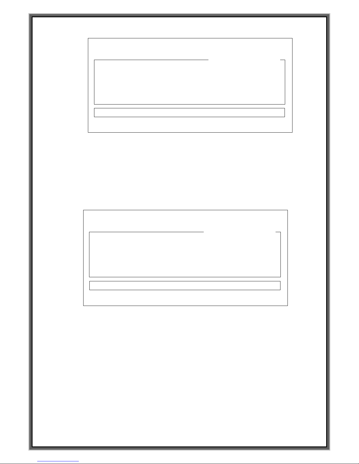
F2 Screen : A_MARK
F1 : M_MENU F2 : A_MARK F3 : EDIT F4 : FILE
F5 : SETUP F6 : TEST F7 : LOAD F8 : COMM
BLK NO. [ 000 ]
PLC INPUT SIGNAL [ . . . . . . . . ] [ . . . . . . . . ]
15:15:22 0.00 STATUS [ ]
[AUTO MARKING MODE]
F9 : SIMULATION F10 : MARK F11 : HOME
MARK_UP_TO[ 00000000 ] UNIT_NO[00001713]
< CURRENT DATA >
(F2) A_MARK screen is the mode which can mark marking data which is inputted on F3 Edit mode
through PLC or external signal on the automation line.
Current marking data and signal which is inputted on PLC are indicated on the screen and
PLC IMPUT SIGNAL.
Basic interface is same as manual marking. Please use this mode when you use it on the automation line.
**Caution**
When the marking machine is ON, you must give RESET signal or press F11 on the keyboard.
READY LAMP of the controller will be ON after marking head confirm Zero point.
READY Signal of external I/O interface is happened at that time.
If the Lamp at READY is turned off, Output at READY of external I/O doesn`t happened.
MARK UP TO (Specified quantity marking) : This function allows you to set a number of
how many pieces of your product to be marked. If you set the number like [00000100] to MARK_UP_TO,
when marked quantity reached this number, the system will be stopped automatically
**Caution – In case there`s value to the MARK UP TO , UNIT END indicate to the STATUS window
and then marking doesn`t start. In this case you must make it [00000000]
<CURRENT DATA> : Indicate current marking data
UNIT NO : This menu is a counter. It indicates the marking quantity.
Check the PLC interface : In case some signal is inputted to the I/O interface, this [.] is charged [!].
1
2
3
4
5
6
7
1
2
3
4
Page 12

12
PLC INPUT SIGNAL [ . . . . . . . . ] [ . . . . . . . . ]
STROBE
PLC6
PLC5
PLC4 PLC START
PLC3 START
PLC2 RESET
PLC1 STOP
PLC0
*STROBE from above pics. is in case of ASCII communication. In case of model selection,
it is recognized PLC7*
09:30:31 : Indicate the current time
0.00 : The cycle time of previous marking data (unit: sec)
STATUS : Indicate the status of marking machine
[ BLOCK ] : In case of marking using PLC START
[ MARKING ] : In case of marking using common START
[ END RUN ] : : In case marking is done
[ EMER STOP ] : It gets the signal “Emergency stop” of PLC and error of the working
[ LIMIT ERROR ] : Limit error
[ Y-DRV.FAULT ] : When the cable of Y-axis motor is cut
[ X-DRV.FAULT ] : When the cable of X-axis motor is cut
[ UNIT END ] : When the specified marking quantity is done
CUSOR_MOVE : ENTER : Moving the cursor and saving the data is the Enter key on the keyboard.
SELECT:SPACE_BAR : Can change the mode of marking by Space_Bar on the keyboard .
F9:SIMULATION : Simulation
F10 :MARK : Real marking
F11:HOME: Return to home position.
5
6
7
Page 13

13
* PLC Signal binary table*
PLC
BLOCK
PLC
BLOCK
PLC
BLOCK
PLC
BLOCK
. . . . . . . .
000
. . . . ! . ! !
011
. . . ! . ! ! .
022
. . ! . . . !
033
. . . . . . . !
001
. . . . ! ! . .
012
. . . ! . ! ! !
023
. . ! . . ! .
034
. . . . . . ! .
002
. . . . ! ! . !
013
. . . ! ! . . .
024
. . ! . . ! !
035
. . . . . . ! !
003
. . . . ! ! ! .
014
. . . ! ! . . !
025
. . ! . ! . .
036
. . . . . ! . .
004
. . . . ! ! ! !
015
. . . ! ! . ! .
026
. . ! . ! . !
037
. . . . . ! . !
005
. . . ! . . . .
016
. . . ! ! . ! !
027
. . ! . ! ! .
038
. . . . . ! ! .
006
. . . ! . . . !
017
. . . ! ! ! . .
028
. . ! . ! ! !
040
. . . . . ! ! !
007
. . . ! . . ! .
018
. . . ! ! ! . !
029
. . ! ! . . .
041
. . . . ! . . .
008
. . . ! . . ! !
019
. . . ! ! ! ! .
030
. . ! ! . . !
042
. . . . ! . . !
009
. . . ! . ! . .
020
. . . ! ! ! ! !
031
. . ! ! . ! .
043
. . . . ! . ! .
010
. . . ! . ! . !
021
. . ! . . . .
032
. . ! ! . ! !
044
.
.
.
You can select PLC upto 256 marking block.
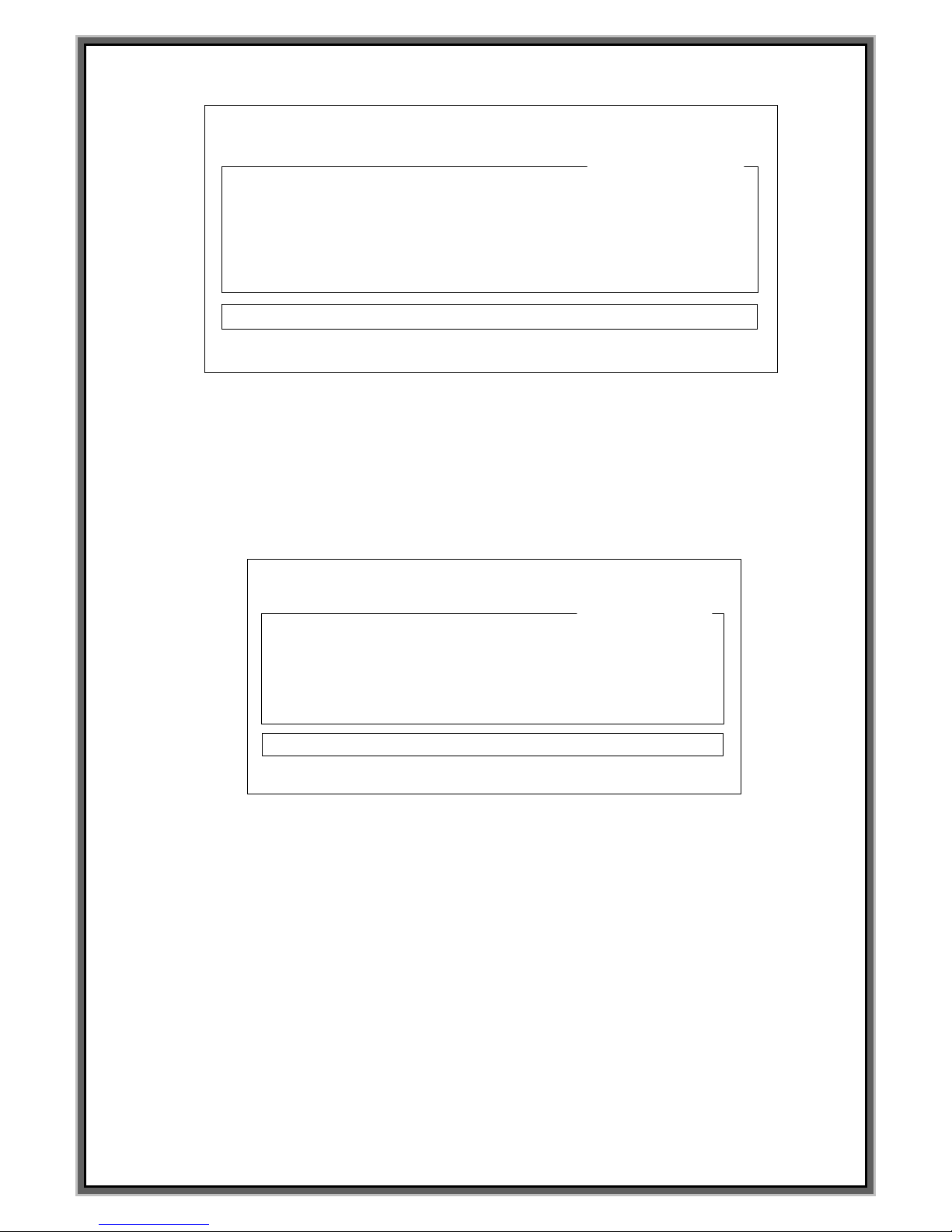
<F2 Screen Multi block>
(F2) A_MARK screen of standard model is as below.
F1 : M_MENU F2 : A_MARK F3 : EDIT F4 : FILE
F5 : SETUP F6 : TEST F7 : LOAD F8 : COMM
BLK NO. [ 000 ]
PLC INPUT SIGNAL [ . . . . . . . . ] [ . . . . . . . . ]
15:15:22 STATUS [ ]
[AUTO MARKING MODE]
F9 : SIMULATION F10 : MARK F11 : HOME
MARK_UP_TO[ 00000000 ] UNIT_NO[00001713]
< CURRENT DATA >
JEIL MTECH
In case several line marking is needed by one PLC signal, multi block is very useful.
Multi block is the signal which is under main block upto 20 multi block.
It helps the worker makes the work of many lines marking conveniently.
In order to use multi block mode, you may set Multiple (20) lines Block? [Y] on the [F5] SETUP MODE
***Caution : Have to set Use PLC sequence table? [N] when you use Multi Block on the F5[SETUP].
Page 14
14
F1 : M_MENU F2 : A_MARK F3 : EDIT F4 : FILE
F5 : SETUP F6 : TEST F7 : LOAD F8 : COMM
BLK NO. [ 00.00 ]
PLC INPUT SIGNAL [ . . . . . . . . ] [ . . . . . . . . ]
15:15:22 STATUS [ ]
[AUTO MARKING MODE]
F9 : SIMULATION F10 : MARK F11 : HOME
MARK_UP_TO[ 00000000 ] UNIT_NO[00001713]
< CURRENT DATA >
Block no is changed same as below. (Example between single and multi block)
Single blk marking (3 times contact signal is needed)
Multi blk marking (1 time contact signal is needed)
DATA BLOCK NO.
GR 45 [001]
030423 [002]
000012 [003]
PLC 1
PLC 2
PLC 3
DATA BLOCK No.
GR45 [01.00]
030423 [01.01]
000012 [01.02]
PLC 1
(Automatic marking)
(Automatic marking)
If set up the marking data on the single block marking like above, we must give the contact signal to each block.
But you may give one PLC signal to the [01.00] on the multi block to mark [01.01], [01.02] together .
Page 15

15
F3 EDIT MODE
(F3) Screen : EDIT (LINEAR MARKING) Screen
**CAUTION : Unit of numeric data on EDIT is 0.1mm.
**CAUTION : Can change the mode using [SPACE BAR] on the keyboard.
**CAUTION : Using ENTER” to move the cursor and using (↑,↓) to move block number.
F1 : M_MENU F2 : A_MARK F3 : EDIT F4 : FILE
F5 : SETUP F6 : TEST F7 : LOAD F8 : COMM
BLK NO. [ 000 ]
LIN X : 0300 Y : 0300 A : 000
FNT : STD1 CH:030 PX:030 L:00000000 I:00
<DATA> PAUSE : N
JEIL MTECH
[EDIT MODE]
BLK_COPY : CTRL_C BLK_MOVE : UP/DOWN
CURSOR_MOVE : ENTER SELECT : SPACE_BAR
BLK NO. [ 001 ]
EMT
< NO BLOCK DATA >
1
2
3 4 5 6 7 8 9
10
11
12
Page 16

16
BLK NO.[000] : Block number.
: Select the marking type. (Select the marking type using SPACE BAR)
EMT : Empty block (Default value)
LIN : Linear marking.
CIR : Circular marking.
PLT : Logo file marking after loading CAD file.
CYL : Cylinder marking.
2DM : 2D Data matrix marking
X : The width distance from start point to a lower of first letter (30mm is X:0300 , Unit : 0.1mm)
Y: The height distance from start point to a lower of first letter(30mm is Y:0300. Unit : 0.1mm)
A: Marking direction ( 35 º is A:035.)
% Delicate adjustment of X and Y value on F3 mode %
0152 0152
0151 Press + 0151
Ln X:0150 Y:0150 Ln X : 0150 Y : 0150
(After move the cursor like the above) 0149 Press - 0149
0148 0148
Put the cursor on the coordinates [0000] and press + and – on the keyboard.
Then marking pin move by 0.1mm, can modify marking data.
**Caution – For storing, you have to press “ENTER”key
1
2
ABCDEF
<LIN>
<CIR> <PLT>
A
B
C
D
E
F
ABCDEF
<CYL> <2DM>
직선마킹
원호마킹
로고마킹
원주면마킹
2D DATA
MATRIX
마킹
3
4
5
ABC
X:30mm
Y:30mm
ABC
X:30mm
Y:30mm
A:035
Linear
marking
Circular
marking
LOGO
marking
2D Data
Cylinder
marking
Page 17

17
FONT : Select the letter type.(If press the SPACE BAR, Menu was changed.)
STD1 = Standard font. Normal type. Letter of Aspect Ratio is 4:6 (W:L)
STD2 = Gothic style. Letter of Aspect Ratio is 4:6 (W:L)
STD3 = KS A 0203 Korean standard font
DOT = 5*7 DOT style.
User1~User4 = To load user`s own font.. (Refer to pg.50)
< STD1 > < STD2 > < DOT >
< STD3 > < USER 1 ~ 4 >
CH : Character size 1.0~according to the marking area
PX : Distance between each center of character.
Marked character can be overlapped if the value at PX is too small. Set as PX = CH.
L : Creation increase and decrease of serial number.
EX)(00000010) = First serial marking number is 10
In case you want to use automatic serial number, please key in @L@ according to no. of serial figures.
@LLLL@ : Lot number 0001.0002.0003……0010
I: Creation increase and decrease of serial number.
EX) I: +1 = As the above instance, second marking serial number is 11.
I: -1 = As the above instance, second marking serial number is 9.
P: P is pause
P: Y = The pin wait for the next signal after last letter is marked.
(To wait for next time start signal) Not output END signal
P: N = The pin returns back to home automatically
6
8
ABC
CH:030
PX:030
7
9
10
11
Page 18

18
DATA Screen : Input the data
All letters and fonts in the keyboard can be used. Ex) JEIL MTECH CO.,LTD
Can not mark"@" because it recognized as automatic variable command word.
In case you input like ISAAC@PINMARKING.COM , the letters which are located behind @ can not be
marked correctly because controller recognized it as automatic variable command.
**Remark*
Moving the block on the single block mode : (↓,↑)
Moving the block on the multi block : First 2 main block (Pagn Down, Pagn Up) Last 2 block : (↑,↓)
F3 Screen: Cir (Circular marking)
**Caution : Unit of numeric data on EDIT is 0.1mm.
**Caution : Can change the mode using [SPACE BAR].
**Caution : Can move the cursor using [ENTER] and moving between each block is using (↑,↓).
BLK NO.[000] : Block no.
F1 : M_MENU F2 : A_MARK F3 : EDIT F4 : FILE
F5 : SETUP F6 : TEST F7 : LOAD F8 : COMM
BLK NO. [ 000 ]
CIR X : 0300 Y : 0300 R:000 A:000 D : W+
FNT : STD1 CH:030 PX:030 L:00000000 I:00
<DATA> PAUSE : N
031213
[EDIT MODE]
BLK_COPY : CTRL_C BLK_MOVE : UP/DOWN
CURSOR_MOVE : ENTER SELECT : SPACE_BAR
BLK NO. [ 001 ]
EMT
< NO BLOCK DATA >
11
1
2
3 4 5 8 6
9
11
12
14
1
13
ABC
PAUSE:N 일경우
ABC
PAUSE:Y 일경우
마킹완료후 원점위치로
자동복귀
마킹완료후 마지막 마킹위치
에서 신호(Ex.START 또는 RESET )
대기
7
10
Return to Home position after
marking automatically
Stop after marking at the
last marked position.
Page 19
19
: Select marking type. Press SPACE BAR to change the Menu
EMT : Empty block (Default value)
LIN : Linear marking.
CIR : Circular marking.
PLT : Logo file marking after loading CAD file.
CYL : Cylinder marking.
2DM : 2D Data matrix marking
X : Center of circle for X axis from Zero point (30mm is X:0300 <Unit : 0.1mm>
Y: Center of circle for Y axis from Zero point (30mm is X:0300 <Unit : 0.1mm>
R: When it`s ARC marking, a radius from center to start point of marking (Radius 12mm is R:0120)
<Unit 0.1mm>)
A: Select the marking start degree ( 50 º is A:050.)
D(Direction) : W+(can select the marking direction)
W +: To move the marking start point the clockwise.
W -: To move the marking start point the counterclockwise.
Key: Press +, - or SPACE BAR
2
ABCDEF
<LIN>
<CIR> <PLT>
A
B
C
D
E
F
ABCDEF
<CYL> <2DM>
직선마킹
원호마킹
로고마킹
원주면마킹
2D DATA
MATRIX
마킹
3
4
6
5
A
B
C
D
E
F
X:30mm
Y:30mm
A:050
R:12mm
A
B
C
D
E
F
D:W+
6
5
4
3
2
1
D:W-
R:12mm
A:050
X축
Y
축
X축
Y
축
A:050
7
Linear
marking
2D data
marking
Cylinder
Logo
marking
Circular
marking
Page 20
20
> When the center of work piece and the X,Y and R value of circle doesn`t match each other
A
B
C
D
E
F
A
B
C
D
E
F
A
B
C
D
E
F
A
B
C
D
E
F
A
B
C
D
E
F
P r o b l e m
Normal
The letters
are leaned to the
down
The letters
are leaned to the
one way
The center of
letters and
circle don`t
match
The letters is in
the circle
S o l u t i o n
None
Increase the
value of Y
Increase
the value of X
Adjust the
value of X & Y
Increase the
value of R
% Delicate adjustment of X and Y value on F3 mode %
0152 0152
0151 Press + 0151
Ln X:0150 Y:0150 Ln X : 0150 Y : 0150
(After move the cursor like the above) 0149 Press - 0149
0148 0148
Put the cursor on the coordinates [0000] and press + and – on the keyboard.
Then marking pin move by 0.1mm, can modify marking data.
**Caution – For storing, you have to press “ENTER”key
In case the value of R is bigger than the center of circle X,Y, “Limit Error” on the status window can be
indicated on the screen. In this case, please check the value of R.
Page 21

21
FONT : Select the letter type.(If press the SPACE BAR, Menu was changed.)
STD1 = Standard font. Normal type. Letter of Aspect Ratio is 4:6 (W:L)
STD2 = Gothic style. Letter of Aspect Ratio is 4:6 (W:L)
STD3 = KS A 0203 Korean standard font
DOT = 5*7 DOT style.
User1~User4 = To load user`s own font.. (Refer to pg.50)
< STD1 > < STD2 > < DOT >
< STD3 > < USER 1 ~ 4 >
CH : Character size 1.0~according to the marking area.
PX : Distance between each center of character.
Marked character can be overlapped if the value at PX is too small. Set as PX = CH..
L : Creation increase and decrease of serial number.
EX)(00000010) = First serial marking number is 10
In case you want to use automatic serial number, please key in @L@ according to no. of serial figures.
@LLLL@ : Lot number 0001.0002.0003……0010
I : Creation increase and decrease of serial number.
EX) I: +1 = As the above instance, second marking serial number is 11.
I: -1 = As the above instance, second marking serial number is 9.
8
10
ABC
CH:030
PX:030
9
11
12
Page 22

22
P : P is pause
P: Y = The pin wait for the next signal after last letter is marked.
(To wait for next time start signal) Not output END signal
P: N = The pin returns back to home automatically.
DATA Screen : Input the data
All letters and fonts in the keyboard can be used. Ex) JEIL MTECH CO.,LTD
Can not mark"@" because it recognized as automatic variable command word.
In case you input like ISAAC@PINMARKING.COM , the letters which are located behind @ can not be
marked correctly because controller recognized it as automatic variable command.
l *Remark*
Moving the block on the single block mode : (↓,↑)
Moving the block on the multi block : First 2 main block (Pagn Down, Pagn Up) Last 2 block : (↑,↓)
F3 Screen: Logo file marking mode
**Caution : Unit of numeric data on EDIT is 0.1mm.
**Caution : Can change the mode using [SPACE BAR].
**Caution : Can move the cursor using [ENTER] and moving between each block is using (↑,↓).
.
BLK NO.[000] : Block no.
: Select marking type. Press SPACE BAR to change the Menu
EMT : Empty block (Default value)
LIN : Linear marking.
CIR : Circular marking.
PLT : Logo file marking after loading CAD file.
CYL : Cylinder marking.
2DM : 2D Data matrix marking
F1 : M_MENU F2 : A_MARK F3 : EDIT F4 : FILE
F5 : SETUP F6 : TEST F7 : LOAD F8 : COMM
BLK NO. [ 000 ]
PLT X : 0300 Y : 0300 A : 000
FNT : Plt1 CH:030 PX:030 L:00000000 I:00
<DATA> PAUSE : N
[EDIT MODE]
BLK_COPY : CTRL_C BLK_MOVE : UP/DOWN
CURSOR_MOVE : ENTER SELECT : SPACE_BAR
BLK NO. [ 001 ]
EMT
< NO BLOCK DATA >
13
14
1
2
3
4
5 6 7 8 9
10
11
12
1
2
Page 23

23
X : Center of circle for X axis from Zero point (30mm is X:0300 <Unit : 0.1mm>
Y: Center of circle for Y axis from Zero point (30mm is X:0300 <Unit : 0.1mm>
A: Marking direction of PLT logo file (180 º is A:180.) CCW direction by Zero point
% Delicate adjustment of X and Y value on F3 mode %
0152 0152
0151 Press + 0151
Ln X:0150 Y:0150 Ln X : 0150 Y : 0150
(After move the cursor like the above) 0149 Press - 0149
0148 0148
Put the cursor on the coordinates [0000] and press + and – on the keyboard.
Then marking pin move by 0.1mm, can modify marking data.
**Caution – For storing, you have to press “ENTER”key
FONT : Select PLT file on the F7 PLOT LOAD. (Press SPACE BAR to change the menu)
Loading 4 PLT file to PLT1 ~ 4 and then load the PLT file on the F7 PLOT LOAD. (Refer to Pg 51)
CH : PLT file size.
PX : It doesn`t impact to the PLT file marking.
ABCDEF
<LIN>
<CIR> <PLT>
A
B
C
D
E
F
ABCDEF
<CYL> <2DM>
직선마킹
원호마킹
로고마킹
원주면마킹
2D DATA
MATRIX
마킹
3
5
6
8
7
X:30mm
Y:30mm
X:30mm
Y:30mm
A:180
4
Cylinder
marking
2D Data
marking
Logo
Marking
Circular
marking
Linear
Marking
Page 24

24
L : It doesn`t impact to the PLT file marking.
I: It doesn`t impact to the PLT file marking.
P : P is pause
P: Y = The pin wait for the next signal after last letter is marked.
(To wait for next time start signal) Not output END signal
P: N = The pin returns back to home automatically.
l *Remark*
Moving the block on the single block mode : (↓,↑)
Moving the block on the multi block : First 2 main block (Pagn Down, Pagn Up) Last 2 block : (↑,↓)
9
10
11
PAUSE:N 일경우 PAUSE:Y 일경우
마킹완료후 원점위치로
자동복귀
마킹완료후 마지막 마킹위치
에서 신호(Ex.START 또는 RESET )
대기
Stop after marking at
the last marked position
Return to Home position
after marking automatically
Page 25

25
F3 Screen: Cylinder marking
**Caution : Unit of numeric data on EDIT is 0.1mm.
**Caution : Can change the mode using [SPACE BAR].
**Caution : Can move the cursor using [ENTER] and moving between each block is using (↑,↓).
.
BLK NO.[000] : Block no.
: Select marking type. Press SPACE BAR to change the Menu
EMT : Empty block (Default value)
LIN : Linear marking.
CIR : Circular marking.
PLT : Logo file marking after loading CAD file.
CYL : Cylinder marking.
2DM : 2D Data matrix marking
X : Center of circle for X axis from Zero point (30mm is X:0300 <Unit : 0.1mm>
Y: Center of circle for Y axis from Zero point (30mm is X:0300 <Unit : 0.1mm>
R: Radius of work-piece ( Radius 30mm is R:0300.)
F1 : M_MENU F2 : A_MARK F3 : EDIT F4 : FILE
F5 : SETUP F6 : TEST F7 : LOAD F8 : COMM
BLK NO. [ 000 ]
CYL X : 0300 Y : 0300 R:150 A:000
FNT : STD1 CH:030 PX:030 L:00000000 I:00
<DATA> PAUSE : N
ABCD
[EDIT MODE]
BLK_COPY : CTRL_C BLK_MOVE : UP/DOWN
CURSOR_MOVE : ENTER SELECT : SPACE_BAR
BLK NO. [ 001 ]
EMT
< NO BLOCK DATA >
1
2
3 4 5 7 6
8
10
11
13
12
9
2
ABCDEF
<LIN>
<CIR> <PLT>
A
B
C
D
E
F
ABCDEF
<CYL> <2DM>
직선마킹
원호마킹
로고마킹
원주면마킹
2D DATA
MATRIX
마킹
3
5
1
4
Linear
Marking
Circular
marking
Cylinder
marking
2D Data
marking
Logo
marking
Page 26
26
A: Direction of the marking.
In case you set the marking machine like above pics.
A:000 -> Marking toward X+direction based on Zero point
A:090 -> Marking toward Y- direction based on Zero point
A:180 -> Marking toward X-direction based on Zero point
A:270 -> Marking toward Y+direction based on Zero point
% Delicate adjustment of X and Y value on F3 mode %
0152 0152
0151 Press + 0151
Ln X:0150 Y:0150 Ln X : 0150 Y : 0150
(After move the cursor like the above) 0149 Press - 0149
0148 0148
Put the cursor on the coordinates [0000] and press + and – on the keyboard.
Then marking pin move by 0.1mm, can modify marking data.
**Caution – For storing, you have to press “ENTER”key
Motor
Y-Axis
적용모델: MK-200, MK-073
MK-200 INDEX
X-
X+
Y-
Y+
마킹작업 방향
X+
X-
6
ABCD
ABCD
ABCD
ABCD
A:000
A:180
A:270
A:090
Page 27

27
FONT : Select PLT file on the F7 PLOT LOAD. (Press SPACE BAR to change the menu)
Loading 4 PLT file to PLT1 ~ 4 and then load the PLT file on the F7 PLOT LOAD. (Refer to Pg 51)
< STD1 > < STD2 > < DOT >
< STD3 > < USER 1 ~ 4 >
CH : Character size 1.0~according to the marking area.
PX : Distance between each center of character.
Marked character can be overlapped if the value at PX is too small. Set as PX = CH.
L : Creation increase and decrease of serial number.
EX)(00000010) = First serial marking number is 10
In case you want to use automatic serial number, please key in @L@ according to no. of serial figures.
@LLLL@ : Lot number 0001.0002.0003……0010
I : Creation increase and decrease of serial number.
EX) I: +1 = As the above instance, second marking serial number is 11.
I: -1 = As the above instance, second marking serial number is 9.
P : P is pause
P: Y = The pin wait for the next signal after last letter is marked.
(To wait for next time start signal) Not output END signal
P: N = The pin returns back to home automatically.
ABC
CH:030
PX:030
8
11
10
7
10
13
Page 28
28
DATA Screen : Input the data
All letters and fonts in the keyboard can be used. Ex) JEIL MTECH CO.,LTD
Can not mark"@" because it recognized as automatic variable command word.
In case you input like ISAAC@PINMARKING.COM , the letters which are located behind @ can not be
marked correctly because controller recognized it as automatic variable command.
l *Remark*
Moving the block on the single block mode : (↓,↑)
Moving the block on the multi block : First 2 main block (Pagn Down, Pagn Up) Last 2 block : (↑,↓)
13
ABC
PAUSE:N 일경우
ABC
PAUSE:Y 일경우
마킹완료후 원점위치로
자동복귀
마킹완료후 마지막 마킹위치
에서 신호(Ex.START 또는 RESET )
대기
Return to Home position
after marking automatically
Return to Home position
after marking automatically
Page 29
29
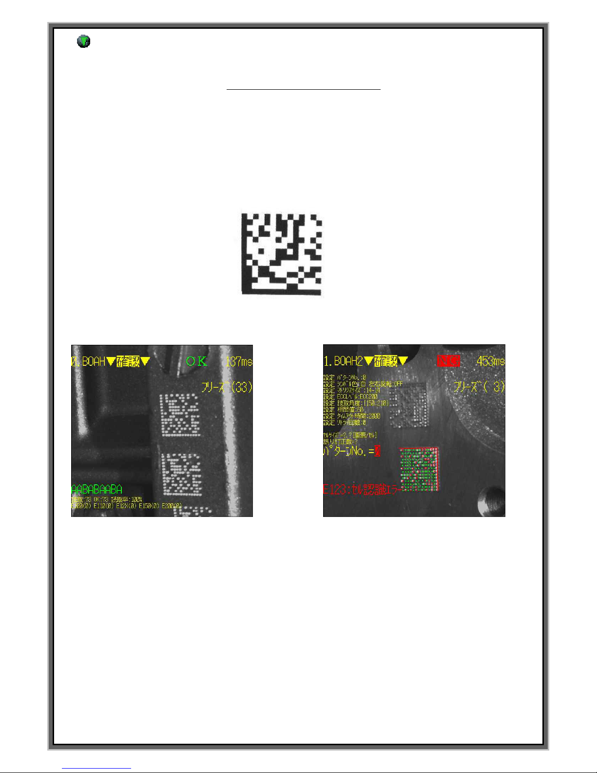
F3 Screen: 2D MATRIX edit mode
What is the 2D DATA MATRIX?
2D has a good function which store a lot of data more than 1D bar code. 2D is recognized by 2D
reader and 2D can be stored a lot of data. Therefore it is suitable to the mark of the automated line.
In this mode, when it marks the inputted data and number. This mode make them convert to 2D code.
And then marks with a data in the square and store the data.
Being used 2D code on MK-series is ECC-200,each data is marked by a dot in the square.
It marks like above and a small cell is indicated a Dot.
Below pictures are to recognize the marked data on the engine block by 2D code reader.
[Picture1: Good screen of 2D code] [Picture2: Failure screen of 2D code]
Picture 1 recognize the 2D code exactly and picture 2 is failure due to moisture, oil and foreign substances.
Because mark of the 2D code use the light and shade of engrave worth a dot, if Dot is veiled, it may not be
recognized. Before use 2D code, remove foreign substances.
Page 30

30
**Caution : Unit of numeric data on EDIT is 0.1mm.
**Caution : Can change the mode using [SPACE BAR].
**Caution : Can move the cursor using [ENTER] and moving between each block is using (↑,↓).
.
BLK NO.[000] : Block no.
: Select marking type. Press SPACE BAR to change the Menu
EMT : Empty block (Default value)
LIN : Linear marking.
CIR : Circular marking.
PLT : Logo file marking after loading CAD file.
CYL : Cylinder marking.
2DM : 2D Data matrix marking
X : Center of circle for X axis from Zero point (30mm is X:0300 <Unit : 0.1mm>
Y: Center of circle for Y axis from Zero point (30mm is X:0300 <Unit : 0.1mm>
A: Marking direction of 2D DATA MATRIX ( Counterclockwise from home position )
F1 : M_MENU F2 : A_MARK F3 : EDIT F4 : FILE
F5 : SETUP F6 : TEST F7 : LOAD F8 : COMM
BLK NO. [ 000 ]
2DM X : 0300 Y : 0300 A :000
SIZE : 16X16 DP:050 L:00000000 I:00
<DATA> PAUSE : N
ABABBAAA
[EDIT MODE]
BLK_COPY : CTRL_C BLK_MOVE : UP/DOWN
CURSOR_MOVE : ENTER SELECT : SPACE_BAR
BLK NO. [ 001 ]
EMT
< NO BLOCK DATA >
1
2
3 4 5
7
6
9
10
11
8
2
ABCDEF
<LIN>
<CIR> <PLT>
A
B
C
D
E
F
ABCDEF
<CYL> <2DM>
직선마킹
원호마킹
로고마킹
원주면마킹
2D DATA
MATRIX
마킹
3
1
2D data
Marking
LOGO
Marking
Circular
Marking
Linear
Marking
Cylinder
Marking
4
5
Page 31

31
% Delicate adjustment of X and Y value on F3 mode %
0152 0152
0151 Press + 0151
Ln X:0150 Y:0150 Ln X : 0150 Y : 0150
(After move the cursor like the above) 0149 Press - 0149
0148 0148
Put the cursor on the coordinates [0000] and press + and – on the keyboard.
Then marking pin move by 0.1mm, can modify marking data.
**Caution – For storing, you have to press “ENTER”key
DP : Adjust the gap between each cell of 2D DATA MATRIX. (Unit : 0.01 mm)
DP:100 is 1mm.
6
X:30mm
Y:30mm
X:30mm
Y:30mm
A:000
A:090
A:180
A:270
1mm
DP:100
SIZE:C12X12
SIZE:C12X12
Page 32
32
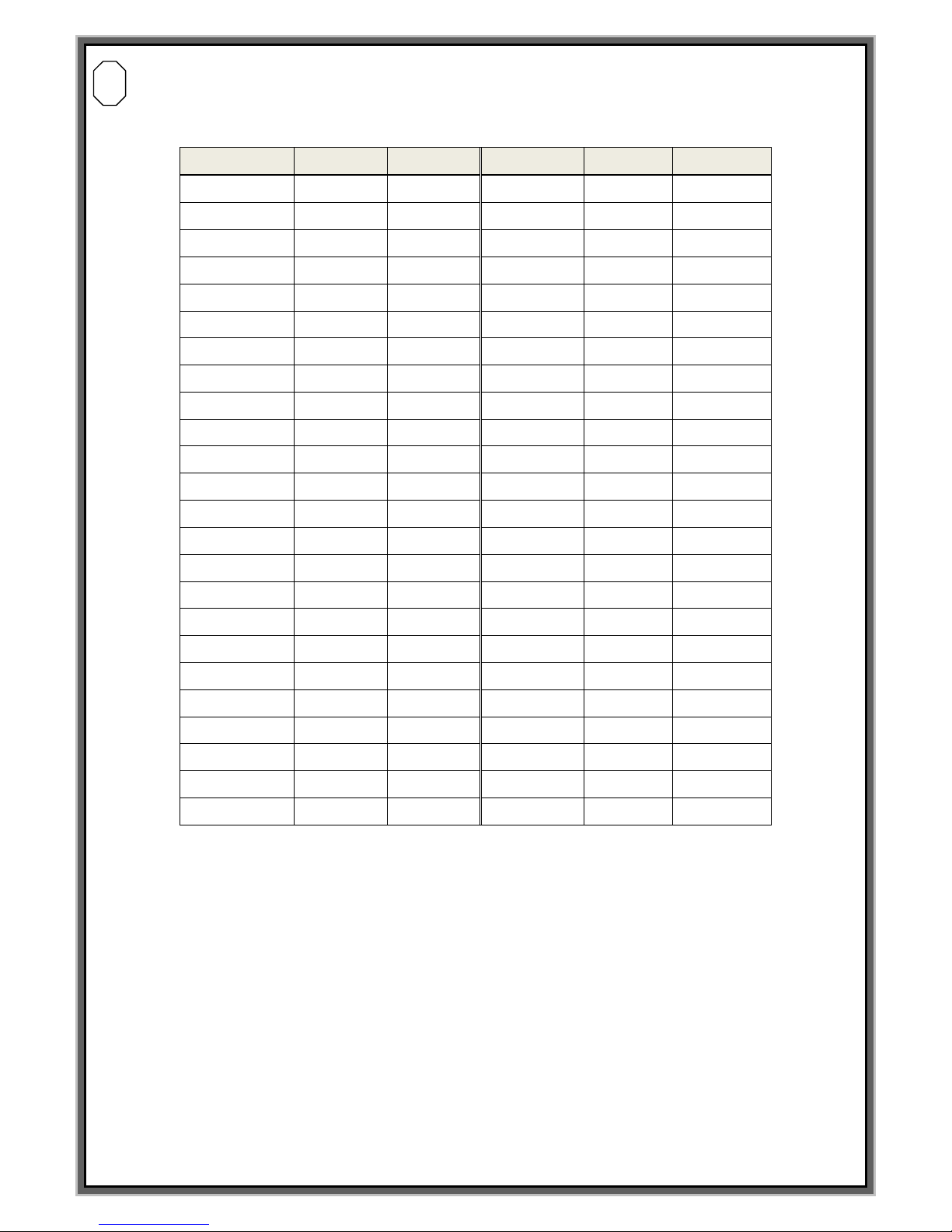
SIZE : Select the no. of cell during 2D DATA MATRIX marking.
Please see the below chart for the reference of the data for each size.
SIZE
No.
Alp. Cha.
SIZE
No.
Alp. Cha.
AUTO
3116
2335
8 x 18
10
6
C12 X 12
10 6 8 x 32
20
13
C14 x 14
16
10
12 x 26
32
22
C16 x 16
24
16
12 x 36
44
31
C18 x 18
36
25
16 x 36
64
46
C20 x 20
44
31
16 x 48
98
72
C22 x 22
60
43
C24 x 24
72
52
C26 x 26
88
64
C32 x 32
124
91
C36 x 36
172
127
C40 x 40
228
169
C44 x 44
288
214
C48 x 48
348
259
C52 x 52
408
304
C64 x 64
560
418
C72 x 72
736
550
C80 x 80
912
682
C88 x 88
1152
862
C96 x 96
1392
1042
C104 x 104
1632
1222
C120 x 120
2100
1573
C132 x 132
2608
1954
C144 x 144
3116
2335
Cell No. will be selected automatically when it is set up AUTO depending on no. of marking data.
Ex> When you mark “6 digit Number” as 2D data matrix, it is marked no. of 10 X 10 as 2D marking.
When you mark “7 digit Number” as 2D data matrix, it is marked no. of 12 X 12 as 2D marking..
If the marking data is more than 10 digit number and 6 cha., Cel size is changed to 14 x 14
automatically even you select C12 x 12.
-> Can avoid the no. of cell size is changed depending on the data if you set it up with
the most amount of data2D DATA
7
Page 33

33
L : Creation increase and decrease of serial number.
EX)(00000010) = First serial marking number is 10
In case you want to use automatic serial number, please key in @L@ according to no. of serial figures.
@LLLL@ : Lot number 0001.0002.0003……0010
I : Creation increase and decrease of serial number.
EX) I: +1 = As the above instance, second marking serial number is 11.
I: -1 = As the above instance, second marking serial number is 9.
P : P is pause
P: Y = The pin wait for the next signal after last letter is marked.
(To wait for next time start signal) Not output END signal
P: N = The pin returns back to home automatically..
DATA Screen : Input the data
All letters and fonts in the keyboard can be used. Ex) JEIL MTECH CO.,LTD
Can not mark"@" because it recognized as automatic variable command word.
In case you input like ISAAC@PINMARKING.COM , the letters which are located behind @ can not be
marked correctly because controller recognized it as automatic variable command.
l *Remark*
Moving the block on the single block mode : (↓,↑)
Moving the block on the multi block : First 2 main block (Pagn Down, Pagn Up) Last 2 block : (↑,↓)
9
12
PAUSE:N 일경우 PAUSE:Y 일경우
마킹완료후 원점위치로
자동복귀
마킹완료후 마지막 마킹위치
에서 신호(Ex.START 또는 RESET )
대기
11
13
Return to Home position
after marking automatically
Return to Home position after
marking automatically
Page 34
34
(F3) Screen: Edit PLC SEQUENCE mode (Press F3 F3 twice to use this mode)
F1 : M_MENU F2 : A_MARK F3 : EDIT F4 : FILE
F5 : SETUP F6 : TEST F7 : LOAD F8 : COMM
SOOO // H / B000 /H / / /
SOO1 // H / B001 /H / / /
SOO2 // H / B002 /H / / /
SOO3 // H / B003 /H / / /
SOO4 // H / B004 /H / / /
SOO5 // H / B005 /H / / /
SOO6 // H / B006 /H / / /
SOO7 // H / B007 /H / / /
[SEQUENCE EDIT]
BLK_COPY : CTRL_C BLK_MOVE : UP/DOWN
CURSOR_MOVE : ENTER SELECT : SPACE_BAR
Sequence table is as single block, it is used as like multi block. Multi block which can mark several lines data
with 1 signal but Sequence table has to be maintained marking data and sequence data together.
Ex> In case 3 lines datas are marked.
Single block marking
(Need to 3 points of contact)
Sequence table (Need to a point of contact)
S001 // H // B001 / B002 / B003 / H /
DATA BLK NO.
GR 45 [001]
030423 [002]
000012 [003]
PLC Signal 1
PLC Signal 2
PLC Signal 3
DATA BLK NO.
GR45 [001]
030423 [002]
000012 [003]
PLC Signal 1
(Auto marking)
(Auto marking)
In case the above, single block marking is needed 3 times start signal.
But 3 lines marking data can be marked with only 1 time start signal on the sequence table
if you set it like above.
S000(Sequence block): Signal no. which get from PLC.(Refer to Pg.12 )
Ex) In case PLC0 + PLC START, select “S001”
B000(): Programmed subordinate block of the sequence block. You can change the marking order you want
.
H -> Return to home position after marking.
(When there is not “H” to the last marked data, it doesn`t return to home position after marking.
Then input “End” signal.
P -> Command of“Pause” Function. Marking pin is stopped after marking and then waiting for next signal.
ex) S001// B002 / B000 / B001 / H / / / In case input the data like this
PLC signal marks 002 block and 000 block, and then marks 001 block. And last return to start point.
If press “B”, you can input the data and can see initialize B000 and can change the block number.
If press “H”(Zero point), it inputs immediately.
Check! In case Sequence Edit screen isn`t indicated with pressing F3F3 2times,
check “USE PLC SEQUENCE TABLE?” on the F5 screen.
If it is [N], please change it [Y].
Page 35

35
F4 DATA MODE
Page 36
36
F4 Screen : Block and sequence data, store and load of setup information.
If press “F4” on the KEY BOARD, it is changed like MARKING DATE LOAD => MARKING DATA SAVE =>
SEQUENCE FILE LOAD => SEQUENCE FILE SAVE => ALL SETUP LOAD => ALL SETUP SAVE
<MARKING DATA LOAD >
The function, that in advance stored marking data, load to the SD memory card.
At LOAD screen, if you press the direction key, be shown the marking data list of SD card.
After find the file you want and press “enter”, it will start to load, If loading is finished normally
Will be shown the message “LOAD DATA OK” on the status screen
.
<MARKING DATA SAVE>
The function that stored marking data in controller stores to the SD card.
Storing is the backup function of the data. When the data was disappeared by an error of the controller
and interruption of electric power, you can use that function.
Storing finish normally, will be shown the message “SAVE DATA OK” on the status screen
F1 : M_MENU F2 : A_MARK F3 : EDIT F4 : FILE
F5 : SETUP F6 : TEST F7 : LOAD F8 : COMM
FILE NAME [ ]
STATUS [ ]
[MARKING DATA LOAD]
F4 : MARKING DATA SAVE
FILENAME DATA TIME
>< NO FILE >
F1 : M_MENU F2 : A_MARK F3 : EDIT F4 : FILE
F5 : SETUP F6 : TEST F7 : LOAD F8 : COMM
FILE NAME [ ]
STATUS [ ]
[MARKING DATA SAVE]
F4 : SEQUENCE FILE LOAD
FILENAME DATA TIME
>< NO FILE >
Page 37
37
<SEQUENCE FILE LOAD>
F1 : M_MENU F2 : A_MARK F3 : EDIT F4 : FILE
F5 : SETUP F6 : TEST F7 : LOAD F8 : COMM
FILE NAME [ ]
STATUS [ ]
[SEQUENCE FILE LOAD]
F4 : SEQUENCE FILE SAVE
FILENAME DATA TIME
>< NO FILE >
The function, the stored sequence file of the controller that you setting up on the F3 mode, loads
On the SD card. At load screen, if you press the direction key, be shown the Marking
Data list of sequence files. After find the file you want and press“ENTER”, it will start load.
If loading is finished normally, will be shown the message “LOAD DATA OK” on the status screen
<SEQUENCE FILE SAVE>
F1 : M_MENU F2 : A_MARK F3 : EDIT F4 : FILE
F5 : SETUP F6 : TEST F7 : LOAD F8 : COMM
FILE NAME [ ]
STATUS [ ]
[SEQUENCE FILE SAVE]
F4 : MARKING DATA LOAD
FILENAME DATA TIME
>< NO FILE >
The function that stored marking data in controller stores to the SD card.
Storing is the backup function of the data. When the data was disappeared by an error of the controller
and interruption of electric power, you can use that function.
Storing finish normally, will be shown the message “SAVE DATA OK” on the status screen
Page 38
38
<ALL SETUP LOAD>
F1 : M_MENU F2 : A_MARK F3 : EDIT F4 : FILE
F5 : SETUP F6 : TEST F7 : LOAD F8 : COMM
FILE NAME [ ]
STATUS [ ]
[ALL SETUP LOAD]
F4 : SEQUENCE DATA SAVE
FILENAME DATA TIME
>< NO FILE >
The function that to load setting value in controller stores to the SD card.
Storing is the backup function of the data. When the set value data was disappeared by
an error of the controller and interruption of electric power, you can use that function.
Storing finish normally, be shown the message “LOAD DATA OK” on the status screen
.
<ALL SETUP SAVE>
F1 : M_MENU F2 : A_MARK F3 : EDIT F4 : FILE
F5 : SETUP F6 : TEST F7 : LOAD F8 : COMM
FILE NAME [ ]
STATUS [ ]
[ALL SETUP SAVE]
F4 : MARKING DATA LOAD
FILENAME DATA TIME
>< NO FILE >
The function that inputted the set value of controller stores to the SD card.
Storing is the backup function of the data. When the data was disappeared by an error of the controller
and interruption of electric power, you can use that function.
Storing finish normally, will be shown the message “SAVE DATA OK” on the status screen.
.
Page 39

39
F5 SETUP MODE
Page 40
40
F5 ( SETUP )Screen : PARAMETER
MARK SPEED : Real speed of marking pin.
In case the marking speed is too higher, distance between each dot of cha. become wider
or marking of cha. can be dented.
Refer to below chart and set up the parameter.
Marking pin.
LP-06 , LP-10 , LP-10P LP-Series
PH-16 PH-Series
Effective area
800 ~ 1200
2000 ~ 2300
Proper value
1000
2000
<Normal speed> <In case the MARK SPEED is faster
as compared marking pin.>
MOVE SPEED : Moving speed except for marking
--> Default value of MOVE SPEED is [12000]. In case you set it up higher,
marking location can be changed. You had better keep this value if possible.
ACCEL. RATE : Acceleration rate of motor.
--> Default value of Acceleration rate for motor is [0100].
In case marking location is changed or moving speed of marking pin is too fast,
you can make it..
F1 : M_MENU F2 : A_MARK F3 : EDIT F4 : FILE
F5 : SETUP F6 : TEST F7 : LOAD F8 : COMM
MARK SPEED [ 02000 ]
Use PLC Sequence table ? [ Y ]
Echo mark data to host ? [ Y ]
Move X then Y to offset ? [ Y ]
Move Y then X to home ? [ Y ]
[ SETUP MODE]
CUSOR_MOVE : ENTER F5 : DATE CODE SET
MOVE SPEED [ 12000 ] ACCEL. RATE [0100 ].
X MOTOR [ 10000 ] STEPS/100MM.
Y MOTOR [ 10000 ] STEPS/100MM.
SOL. DN DLY [ 00020 ] SOL. UP DLY [ 00020 ]
END OUT DLY [ 01500 ]
1
2
5
4
8
6
3
7
9
10
12
11
1
2
3
Page 41
41
X MOTOR [10000] steps/100mm. : Standard: 10000purse per 100mm
If the value of X MOTOR [10000] STEPS/100MM is changed, Marking machine may work
incorrectly because the figure of marking machine is wrong. Do not modify.
MK-100BS , MK-85BS , SI-120 - > STEP [ 25000 ]
Another all other marking head그 -> STEP [ 10000 ]
Y MOTOR [10000] steps/100mm. : Standard: 10000purse per 100mm
If the value of X MOTOR [10000] STEPS/100MM is changed, Marking machine
may work incorrectly because the figure of marking machine is wrong. Do not modify.
MK-100BS , MK-85BS , SI-120 - > STEP [ 25000 ]
Another all other marking head그 -> STEP [ 10000 ]
SOL. DN DLY : The delay time of sol. Valve when the marking is started. (Default value [0020] )
SOL. UP DLY : The delay time of sol. Valve when the marking is finished. (Default value [0020] )
< In case the value of SOL. DN DLY is small > <In case the value of SOL. UP DLY is small. >
-> Make it the value of SOL.DN DLY and SOL UP DLY higher a little by a little.
END. OUT DLY : Output the “END” signal after marking and keep the output value during 1.5 sec.
Unit of delay [01500] is 0.001sec.
USE PLC SEQUENCE TABLE? : Default value is [Y]. Make it [N] in case you use multi block.
4
5
6
7
8
9
Page 42

42
ECHO MARK DATA TO HOST? : Transfer the log data by RS-232 port after marking
( Default is [Y] )
MOVE X THEN Y TO OFFSET ? :
Select the order of marking direction during marking pin is progressing.
Select the axis which is moving earlier .
-> Default value is [Y]. X axis is moved earlier then move to Y axis.
MOVE Y THEN X TO HOME ? :
Select the order of marking direction during marking pin is returning.
-> Default value is [Y]. Y axis is moving earlier then move to X axis .
Item
Default value
Setting value
of LP-pin
Setting value
of PH-pin
MARK SPEED
2000
800 ~ 1400
2000
MOVE SPEED
12000
12000
12000
ACCEL.RATE
100
50 ~ 100
50 ~ 100
X MOTOR
10000
10000
10000
Y MOTOR
10000
10000
10000
SOL. DN DLY
20
20
20
SOL. UP DLY
20
20
20
END OUT DLY
1500
1500
1500
USE PLC SEQUENCE TABLE?
Y Y Y
ECHO MARK DATA TO HOST?
Y Y Y
MOVE X THEN Y OFFSET?
Y Y Y
MOVE Y THEN X HOME?
Y Y Y
10
12
11
ABC
MOVE X THEN Y TO OFFSET [Y] 일 경우
ABC
MOVE X THEN Y TO OFFSET [N] 일 경우
1
1
2
2
ABC
MOVE Y THEN X TO HOME [Y] 일 경우
ABC
MOVE Y THEN X TO HOME [N] 일 경우
1
1
2
2
Page 43
43
Press “Enter”, the screen is changed as below :
MULTIPLE (20) LINES BLOCK ? Select Multi Block (Refer to pg 13). (Default value is “N” )
-> In case you use multi block, please make it [Y] from [N[
OPTIMIZE 2D MATRIX MARKING ? : Select the type of 2D DATA MATRIX.
-> In case [Y], 2D DATA MATRIX is marked zig-zag.
In case [N], 2D DATA MATRIX is marked to one direction.
SOFTWARE HEAD PARKING ? :
Virtual origin function to determine whether to use. Default value is [N].
If this value is [Y], marking machine doesn`t return to home position.
Marking is finished after moving to the location which you assign on
.
SAVE MARK DATA TO LOG FILE ? : Deciding whether to use for saving the log data
to the USB and SD card as TXT file. ( Dafault value is [N] )
F1 : M_MENU F2 : A_MARK F3 : EDIT F4 : FILE
F5 : SETUP F6 : TEST F7 : LOAD F8 : COMM
X PARK POSITION [0000] 0.1mm./step
Y PARK POSITION [0000] 0.1mm./step
Reset Every [0000] Mark Cycles
Multiple (20) lines Block ? [ Y ]
Optimize 2DMatrix marking ? [ Y ]
Software Head Parking ? [ Y ]
Save mark data to log file ? [ Y ]
[ SETUP MODE]
CUSOR_MOVE : ENTER F5 : DATE CODE SET
Log Folder Name :
Log File Name :
17
18
19
20
21
13
14
16
15
13
14
OPTIMIZE 2D MATRIX MARKING? [ Y ] 일 경우 OPTIMIZE 2D MATRIX MARKING? [ N ] 일 경우
15
17
18
16
Page 44

44
X PARK POSITION [0000] 0.1mm./step : X axis of Virtual origin which marking pin will come
after marking is finished in case using this function. ( Unit : 0.1 mm )
Y PARK POSITION [0000] 0.1mm./step : Y axis of Virtual origin which marking pin will come
after marking is finished in case using this function. ( Unit : 0.1 mm )
Ex> In case X PARK POSITION [0050]and Y PARK POSITION [0200]
RESET EVERY [0000] MARK CYCLES : Return to home position after specify the quantity.
And then stand by at specified location.
-> Marking location is changed during using virtual origin,
change the value of “ RESET EVERY [0000]”periodically to check the location of marking pin from
home position of marking head.
LOG FOLDER NAME : In case using this function, designate the folder name
which log file will be saved.
LOG FILE NAME : In case using this function, designate the name of log file.
17
18
19
20
21
ABC
SOFTWARE HAED PARKING? [N] 일경우
ABC
마킹완료후 원점위치로
자동복귀
마킹완료후 지정된 X,Y 좌표
위치로 복귀
SOFTWARE HAED PARKING? [Y] 일경우
Y:0200
X:0050
Return to home position
after marking is finished
Return to designated X&Y
axis after marking is finished
Page 45

45
(F5) Screen : Team code. Year, Month, day, etc (Activated by press F5F5 twice)
Above is the set-up screen of teamt code. Can change the rotation time on this screen,
You can change the shift code on this screen. Team code can be inputted up to 24..
-> In case adding the shift code, press “Enter” and let Cursor move to empty code and input the code.
NO 4TH SHIFT will be changed FROM[00:00:00]. And then set up the time of shift code.
Set up the working time of team code on this screen.
Only FROM[00:00:00] can be modified and behind of TO[07:59:59] is inputted automatically.
1
2
1
2
F1 : M_MENU F2 : A_MARK F3 : EDIT F4 : FILE
F5 : SETUP F6 : TEST F7 : LOAD F8 : COMM
TEAM CODE
[ DATE CODE SET ]
CUSOR_MOVE : ENTER F5 : MOTOR/OPTIONS
1.[ A ] = FROM [00:00:00] TO [07:59:59]
2.[ B ] = FROM [08:00:00] TO [15:59:59]
3.[ C ] = FROM [16:00:00] TO [23:59:59]
4.[ ] = NO 4TH SHIFT
5.[ ] = NO 5TH SHIFT
6.[ ] = NO 6TH SHIFT
7.[ ] = NO 7TH SHIFT
8.[ ] = NO 8TH SHIFT
Page 46

46
Can see the below screen if press “Enter” on the above screen.
YEAR CODE : Command word of YEAR code is @Z@.
Refer to above chart.
-> Y-0 : 2010 , Y-1 : 2011 , Y-2 : 2012 , Y-3 : 2013 , Y-4 : 2014 ,
Y-5 : 2015 , Y-6 : 2016 , Y-7 : 2017 , Y-8 : 2018 , Y-9 : 2019
After 2020, change the last digit of year.
2020년->Y-0 , 2021년 -> Y-1 , 2022년->Y-2 , 2023년 -> Y-3 , 2024년->Y-4 ......
MONTH CODE : Command word of YEAR code is @N@.
Refer to above chart.
-> JAN : 1 / FEB : 2 / MAR : 3 / APR : 4 / MAY : 5 / JUNE : 6 / JUL : 7 / AUG : 8
SEP : 9 / OCT : 10 / NOV : 11 / DEC : 12
DATE CODE : Command word of YEAR code is @N@.
Refer to above chart.
Ex) In case input @ZNE@ on the F3(Edit mode) after setting up like above screen
If the current date is 8th Feb 2013, marking data will be “D2H”.
F1 : M_MENU F2 : A_MARK F3 : EDIT F4 : FILE
F5 : SETUP F6 : TEST F7 : LOAD F8 : COMM
YEAR CODE
[ DATE CODE SET ]
Y-0[ A ] Y-1[ B ] Y-2[ C ] Y-3[ D ] Y-4[ E ]
Y-5[ F ] Y-6[ G ] Y-7[ H ] Y-8[ I ] Y-9[ J ]
MONTH CODE
JAN [ 1 ] FEB [ 2 ] MAR [ 3 ] APR [ 4 ] MAY [ 5 ] JUNE [ 6 ]
JUL [ 7 ] AUG [ 8 ] SEP [ 9 ] OCT [ X ] NOV [ Y ] DEC [ Z ]
DATE CODE 1[A] 2[B] 3[C]
4 [D] 5[E] 6[F] 7[G] 8[H] 9[I] 10[J]
11[K] 12[L] 13[M] 14[N] 15[O] 16[P] 17[Q]
18[R] 19[S] 20[T] 21[U] 22[V] 23[W] 24[X]
25[Y] 26[Z] 27[1] 28[2] 29[3] 30[4] 31[5]
1
2
3
1
2
3
Page 47

47
F6 TEST MODE
Page 48
48
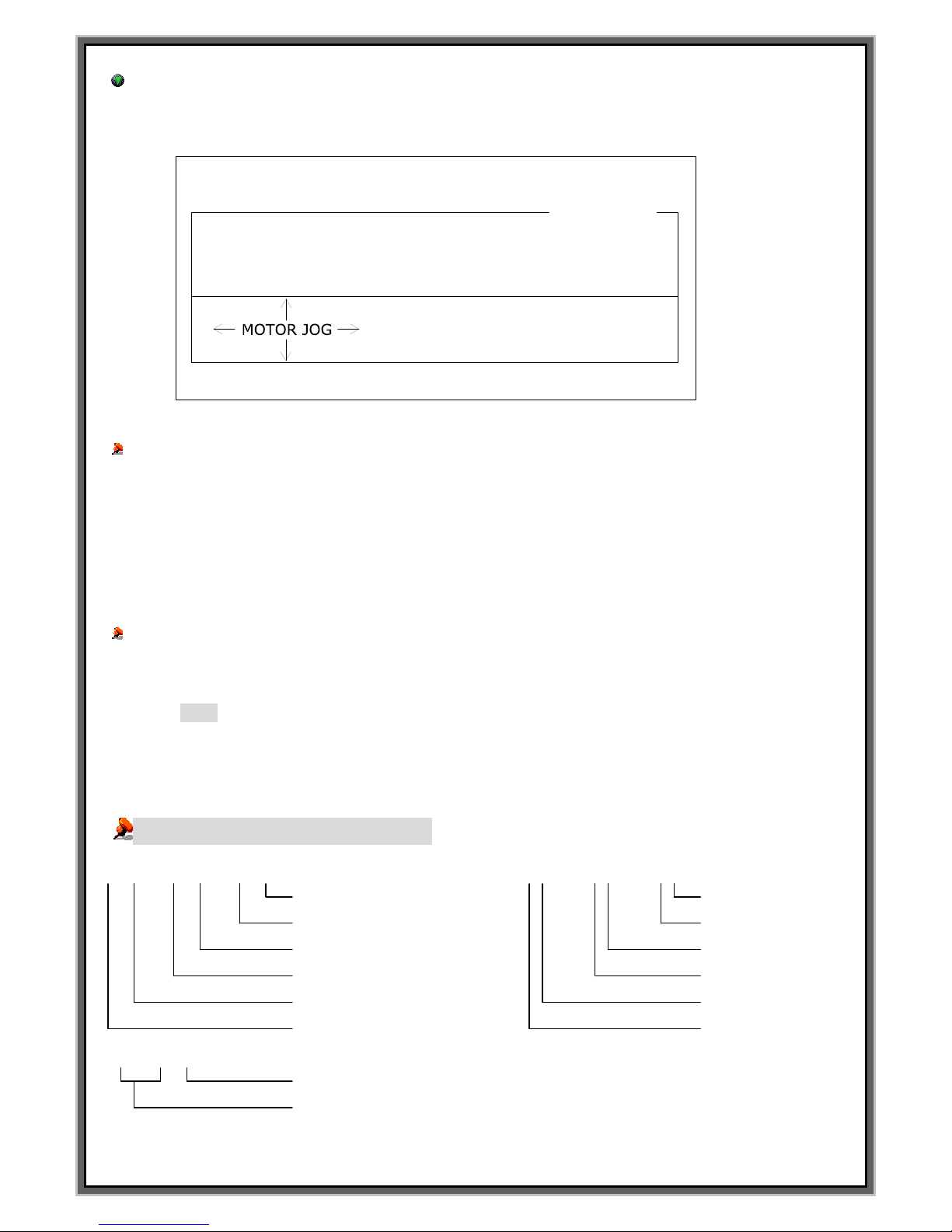
F6 ( TEST ) Screen :
Check the condition of each parts and moving and modify the date and time on the controller.
F1 : M_MENU F2 : A_MARK F3 : EDIT F4 : FILE
F5 : SETUP F6 : TEST F7 : LOAD F8 : COMM
X_HOME X_LIMIT Y_HOME Y_LIMIT
[ TEST MODE]
DATE_SET : Yy Mm Dd TIME_SET : Hh Bb Ss
2006/ 05/ 26 12: 45: 45
SENSOR [OFF] [OFF] [OFF] [OFF]
SOL. VALVE1: [OFF] SOL.VALVE2: [OFF]
SOL. ON : DEL_KEY SOL. OFF :INS_KEY
X POSITION = 20.00mm.
Y POSITION = 20.00mm.
Check the step motor:
At F6 mode, if you press an arrow keyà The pin will go to the right hand side.
Whenever you click the Arrow key, marking pin moves per 10mm.
Also if you press no. “5” on the keyboard, the pin will return to home position.
You can check the condition of the step motor of X/Y –axis here.
It is the problem of the motor if the pin was not moving to the any direction.
please check the motor and driver which Axis has problem
CHECK the Sol. Valve:
Check the condition of sol. Value whether to check the stroke of marking pin. It is the problem if the
marking pin doesn`t come out.
l If you press “DEL” on the keyboard, ”SOL. Valve 1””SOL. VALVE 2”on the controller is ON.
l In order to let it OFF, press “INS” key on the keyboard.
You can adjust the date and the time on the F6 mode..
Adjustment of the data and the time (F6 TEST MODE)
1 5 : 2 2 : 0 2 Adjustment 20 0 6: 0 5: 2 2: Adjustment
Press S Press D
Press (Shift+S) Press (Shift+D)
Press B Press M
Press (Shift+B) Press (Shift+M)
Press H Press Y
Press (Shift+H) Press (Shift+Y)
2 0 0 7
Press Y ( 0~9)
Press Shift + Y
200->201->202->->210
*Can be set up from 2000 to 2199
Page 49

49
F7 FILE LODE MODE
Page 50
50
F7 screen : Marking of the special cha.
and Installation of the file which are created on the AUTO-CAD or Font generator.
In order to use User font, you should carry out this work in advance on the F3 EDIT mode.
F1 : M_MENU F2 : A_MARK F3 : EDIT F4 : FILE
F5 : SETUP F6 : TEST F7 : LOAD F8 : COMM
LOAD TO [USR1] FONT
STATUS [ ]
[FONT LOAD]
F7 : PLOT LOAD
FILENAME DATA TIME
>< NO FILE >
<Installation of User font>
Can change the menu if press “F7” on the keyboard. Press F7, display is changed to [ FONT LOAD ],
Press F7F7, display is changed to [ PLOT LOAD ].
** How to load User font to the USER1
Press F7 and let the controller displays [FONT LOAD]. Select the no. which is in [ ]
by Enter key on the keyboard. Can select from USER1 to USER 4.
Then put the cursor on ‘<NO FILE>’by PgUP and PgDN key.
In order to see the USER fonts which are saved in the SD card,
press arrow key(↓) if the cursor is on ‘<NO FILE>’
F1 : M_MENU F2 : A_MARK F3 : EDIT F4 : FILE
F5 : SETUP F6 : TEST F7 : LOAD F8 : COMM
LOAD TO [USR1] FONT
STATUS [ ]
[FONT LOAD]
F7 : PLOT LOAD
FILENAME DATA TIME
< NO FILE >
COLUMBIA.BLK 1998/06/05 12:45
MARKSMAN.BLK 1998/06/05 12:45
JEILMTECH.BLK 1998/06/05 12:45
Selected font will be loaded into the MCU if you press “Enter”key on the keyboard after select the font.
In case Loading is completed, “Reading Data OK” is indicated on the STATUS[ ] window.
Can have new type of font to designated USER 1 ~ 4 on the F3 mode
if the message “Reading data OK”is indicated on the display.
Page 51

51
In order to mark logo file, you should carry out this work in advance on the F3 EDIT mode..
F7 screen : Marking of the special cha.
and Installation of the file which are created on the AUTO-CAD or Font generator.
F1 : M_MENU F2 : A_MARK F3 : EDIT F4 : FILE
F5 : SETUP F6 : TEST F7 : LOAD F8 : COMM
LOAD TO [PLT1] PLOT
STATUS [ ]
[PLOT LOAD]
F7 : FONT LOAD
FILENAME DATA TIME
>< NO FILE >
** How to load User font to the PLT1
Press F7 and let the controller displays [PLOT LOAD]. Select the no. which is in LOAD TO [PLT1 ]
by Enter key on the keyboard if above screen is displayed. Can select from PLT1 to PLT4.
Then put the cursor on ‘<NO FILE>’by PgUP and PgDN key.
Can see the PLT files which are saved in the SD card If press direction key(↓)
F1 : M_MENU F2 : A_MARK F3 : EDIT F4 : FILE
F5 : SETUP F6 : TEST F7 : LOAD F8 : COMM
LOAD TO [PLT1] PLOT
STATUS [ ]
[PLOT LOAD]
F7 : FONT LOAD
FILENAME DATA TIME
COLUMBIA.PLT 1998/06/05 12:45
MARKSMAN.PLT 1998/06/05 12:45
JEILMTECH.PLT 1998/06/05 12:45
< NO FILE >
Selected PLT file will be loaded into the MCU if you press “Enter”key on the keyboard
after select the PLT file.
In case Loading is completed, “Reading Data OK” is indicated on the STATUS[ ] window.
Can have new LOGO file to designated PLT 1 on the F3 mode if the message
“Reading data OK”is indicated on the display.
Page 52

52
F8 COMMUNICATION MODE
Page 53

53
F8 ( COMM ) screen: COMMUNICATION mode
Can change the mode if press “F8”, Carry out the command of PC and HOST by RS-232 cable
Malfunction can be happened if you give the signal to the I/O interface on the F8mode.
1. Control Marking machine with a PC
Practical application of standard window program.
USER PROGRAM: In USER`s Program case: Provide JEIL –PROTOCOL
SCALE: 750 (Can be adjusted the received data from CAD.)
BX: 0100, BY: 0100 (Appoint marking start point)
D: X+ (Convert the direction per 90 like F3 mode)
STATUS[MARKING]- Marking, [END RUN]- Finish signal of marking..
F9 ( PREV ) : Moving Backward .Same function with BACK SPACE
F10 ( NEXT ) : Moving Forward. Same function with ENTER
RS-232 PROTOCOL (Control the marking machine by serial communication)
For operating marking machine by PC, you can use your own projecting program or standard program of
JEIL MTECH CO., LTD.
In case using the user`s own s/w, please see following : .
VER 1.0/VER2.0 of Jeil MTech Co.,Ltd standard program
(Writing/Creating your own operation software)
Data format
9600 baud
8 Data bits no parity bit,
1 stop bit, RTS/CTS control of data flow.
F1 : M_MENU F2 : A_MARK F3 : EDIT F4 : FILE
F5 : SETUP F6 : TEST F7 : LOAD F8 : COMM
BLK NO [000]
[ COMMUNICATION MODE]
F9: SIMULATION F10 : MARK F11 : HOME
LIN X : 0500 Y : 0500 A:000
FNT : STD1 CH:040 PX:040 L:00000000 I : 00
<DATA> PAUSE : N
ABC
PLOT SCALE : 750 X:0300 Y:0300 A:000
15:15:22 0.00 STATUS [ ]
Page 54
54
A. Sending data from PC ---> MK-100
Note :: Meaning of <ESC> is 1B at Hexadecimal and it is the space which input “ESC” on the keyboard
Meaning of <CAN> is 18 at Hexadecimal and it is the space which input “CTRL-X”on the keyboard
.
(Communication Mode Commends)
Function
Command
Details
Reset Memory
<ESC>@;
Initialization (Memory Clear)
- Select marking mode
LINEAR MARKING
<ESC>G1;
Select LINEAR marking [LIN]
CIRCULAR MARKING
<ESC>G2;
Select CIRCULAR marking [CIR]
PLT MARKING
<ESC>G3;
Select PLT marking [PLT]
CYL MARKING
<ESC>G4;
Select Cylinder marking [CYL]
2DM MARKING
<ESC>G5;
Select 2D data code marking [2DM]
- Select font
STANDARD FONT1
<ESC>H0;
Select STD1 Font
STANDARD FONT2
<ESC>H1;
Select STD2 Font
5X7 DOT
<ESC>H2;
Select dot Font
USR1 Font
<ESC>H3;
Select USER1 or PLT1
USR2 Font
<ESC>H4;
Select USER1 or PLT2
USR3 Font
<ESC>H5;
Select USER1 or PLT3
USR4 Font
<ESC>H6;
Select USER1 or PLT4
- Select marking coordinate
X axis
<ESC>I000;
Input X Axis value
**Caution – Unit is 0.1mm
Ex) <ESC>I050; Move 5mm toward - X
<ESC>I999; Move 99.9mm toward - X
Y axis
<ESC>J000;
Input X Axis value
** Caution – Unit is 0.1mm
Ex) <ESC>J050; Move 5mm toward -Y
<ESC>J999; Move 99.9mm toward - Y
- Select cha. size
Height of letters
<ESC>O000;
The height of letter ( Rate of aspect ratio for cha. is 6:4 )
** Caution – Unit is 0.1mm
Ex) <ESC>O050; - Letter. of which height is 5mm
The gap between
each letters. (PX)
<ESC>M000;
In case more than 2 cha. the distance between the center
of each letter.**Caution – Unit is 0.1mm.
Usually the value between PX and CH is equal.
Ex) <ESC>M050; - 문자의 간격이 5mm 임
- Select the no. of starting serial number and marking direction
Serial number
<ESC>Q00000;
The number of starting serial number.
Ex) <ESC>Q01234; - First serial no. is 1234
Page 55
55
Marking
direction
<ESC>L000;
Select marking direction
(Refer to Pg.13 Marking direction)
Radius of circle
<ESC>K000;
Given the radius value of circle. R
Direction of
circular marking
<ESC>P1;
D:W- , Counterclockwise direction marking
<ESC>P2;
D:W+ , Clockwise direction marking
- Selection of Increase and decrease of serial number
Selection of Increase
and decrease of serial
number
<ESC>R+9;
Increase every 9 from first serial no.
<ESC>R0;
Increase every 0 from first serial no.
<ESC>R-9;
Decrease every -9 from first serial no.
- Select Pause function.
Pause function
<ESC>SY;
Pause : Y The pin wait for the next signal after marks last
letter
<ESC>SN;
Pause : N The pin returns back to home automatically
- Input marking data
Input marking data
<ESC>U****;
The data which marks.
Ex) In case you mark “This is a test”
Command : <ESC>U This is a test;
Select next block
<ESC>Z;
<ESC>Z; Block number will be increased automatically
Limitation of
production quantity
<ESC>$00000;
Set Mark Up To[00000]
Indication of
production quantity
<ESC>#00000;
Unit No[00000] can be changed randomly.
-Other command
Reset function
<ESC>%;
Return to home position
Start function
<ESC>!;
Marking if the data is entered correctly.
Stop function
<CAN>or CTRL-X
Emergency stop during the marking.
Page 56
56
** Getting data from MCU.
To get data from the MK100, you must send a <ESC>? Sequence.
Handle the problem of RS-232 communication by reconfirming data if use this function.
All command word which come from MCU is just add “?” from command word that
you gave to MC from PCU.
Ex) When reconfirm the transferred data,
***Signal which come from controller directly.
Output “END” signal after marking
<ESC>E03;
UNIT END ERROR
<ESC>E05;
LIMIT ERROR
<ESC>E12;
In case the Motor and Driver is broken
<ESC>E18;
Replied data
Command
Reply
Type of block
<ESC>?G;
LINEAR marking: <ESC>G000001;
2DM marking: <ESC>G000005;
Type of font
<ESC>?H;
STD1 : <ESC>H000000;
STD2 : <ESC>H000001;
Coordinate of X
<ESC>?I;
When coordinate of Y is 300 : <ESC>I000300;
Coordinate of Y
<ESC>?J;
When Coordinate of X is 300: <ESC>J000300;
Value of R값 (CIR)
<ESC>?K;
When R is 150 : <ESC>K000150;
Value of A 값 (Angle and
marking direction)
<ESC>?L;
When A is 270 degree: <ESC>L270;
Distance between each
letters
<ESC>?M;
Interval is 30: <ESC>M000030;
Height of letter.
<ESC>?O;
Height is 30 : <ESC>O000030;
Serial number
<ESC>?Q;
Range: <ESC>Q00000001; ~ <ESC>Q00032767;
Marking direction(Cylinder
marking)
<ESC>?P;
D: W+ : <ESC>P00;
D: w- : <ESC>P01;
Creation of increase and
decrease serial number
<ESC>?R;
I: 0 때: <ESC>+0;
I: +1 : <ESC>+1;
I: -1 : <ESC>-1;
Pause function
<ESC>?S;
P: N : <ESC>SN;
P: Y : <ESC>SY;
Marking data
<ESC>?U;
When marking data is‘12345’
<ESC>U12345;
Limitation of product quantity
<ESC>?$;
Range: <ESC>$00000000; ~ <ESC>$99999999;
Total marking quantity
<ESC>?#;
Range: <ESC>#00000000; ~ <ESC>#99999999;
Page 57

57
Example of communication mode
F1 : M_MENU F2 : A_MARK F3 : EDIT F4 : FILE
F5 : SETUP F6 : TEST F7 : LOAD F8 : COMM
BLK NO. [ 000 ]
LN X : 0300 Y : 0300 A : 000
FNT : STD1 CH:030 PX:030 L:00000000 I:+1
<DATA> PAUSE : N
JEIL MTECH
[EDIT MODE]
BLK_COPY : CTRL_C BLK_MOVE : UP/DOWN
CURSOR_MOVE : ENTER SELECT : SPACE_BAR
BLK NO. [ 001 ]
EMT
< NO BLOCK DATA >
In case enter the data like above, enter the data like below order.
1. <ESC>@; //Initialization (Memory Clear)
2. <ESC>G1; // Select LINEAR marking
3. <ESC>H0; // Select STD1 Font
4. <ESC>I300; // Input X Axis value
5. <ESC>J300; // Input Y Axis value
6. <ESC>L000; // Angle value
7. <ESC>M030; // Pitch value between the letters
8. <ESC>O030; // Character size value
9. <ESC>UJEIL MTECH; // Input the marking data
10. <ESC>!; // input the start signal
In case make more than 2 block data, please see the following.
1. <ESC>@; 10.<ESC>Z; // Increment of block no.
2. <ESC>G1; 11.<ESC>G1;
3. <ESC>H0; 12.<ESC>H0;
4. <ESC>I300; 13.<ESC>I300;
5. <ESC>J300; 14.<ESC>J400;
6. <ESC>L000; 15.<ESC>L000;
7. <ESC>M030; 16.<ESC>M030;
8. <ESC>O030; 17.<ESC>O030;
9. <ESC>UJEIL MTECH; 18.<ESC>U12345;
19. <ESC>!;
Do not need to input the value which is “0” (Zero).
Page 58

58
References on the Communication mode program
The above examples can be expressed as 16 digits(Hexadecimal) as follows.
1. 1B 40 3B //Initialization
2. 1B 47 31 3B // Select LINEAR marking
3. 1B 48 30 3B // Select STD1 Font
4. 1B 49 33 30 30 3B // Input X-Axis value
5. 1B 4A 33 30 30 3B // Input Y-Axis value
6. 1B 4C 30 30 30 3B // Select the angle marking
7. 1B 4D 33 30 3B // Pitch value between the letters
8. 1B 4F 33 30 3B // Chracter size value
9. 1B 55 4A 45 49 4C 20 4D 54 45 43 48 3B // Input the marking data
10. 1B 21 3B // input the start signal
Caution : All above value is removed when new command word comes because
“Memory clear” command word is in the first of communication command.
You can use NULL (16digits “00”) value to meet the number of digits in order to set
the statement of communication. But value of NULL should not come in the middle
of the communication statements.. The value of NULL much ne completed after the statement.
Ex ) 1B 4D 33 30 3B 00 à (O) 1B 4D 33 30 00 3B -> (X)
After transferring the statement of ex.1 to ex.12, if you only transfer special data(Marking data)
You can overwrite it.
Ex ) In case of you transfer after transfer back to examples 1B 49 36 30 30 3B
examples of the data is kept and X axis value will be changed 300 to 600.
Command word will be transferred twice, marking machine will mark two times.
(The statement is stored in the buffer)
Therefore if the marking machine marks the data repeatedly, please check the transferring the number of
statements.
Can use automatic marking variable to the marking data.
Ex) In case of mark with a number of the date which is set to the marking machine
( Refer to Automatic marking variable @YYMMDD@ )
-> You may input 1B 55 40 59 59 4D 4D 44 44 40 3B. In this case,
if the value of U are missing, all marking data will be deleted automatically.
Please note it.
Once you create the PLC operation program. if the WORD data 1B 40, real transferring data
will be 40 1B.Therefore you should key in 40 1B in order you to mark 1B 40
Page 59

59
How to Create PLT file
by standard AUTO CAD 2006
Page 60

60
How to create PLT File (By AUTO CAD 2006 LT)
1. Install new plotter before create PLT file. Put the cursor on Command window on Autocad and
Then click right button of mouse. Then select Option.(O)
2. Below screen is indicated if select option(O).
Then select the tab of Print and plot configuration.
Click Add Plotter or (P) to open the window .
3. Installed plotter is indicated same as blow on the Autocad. Execute the plotter wizard
on this screen.
Page 61

61
4. Below screen is indicated. Click the Next.(N).
5. Another screen is indicated if you click next.
Select “My computer” and click “Next”(N).
6. Select the plotter “HP (Hewlett-Packard) 7475A” .
Page 62
62
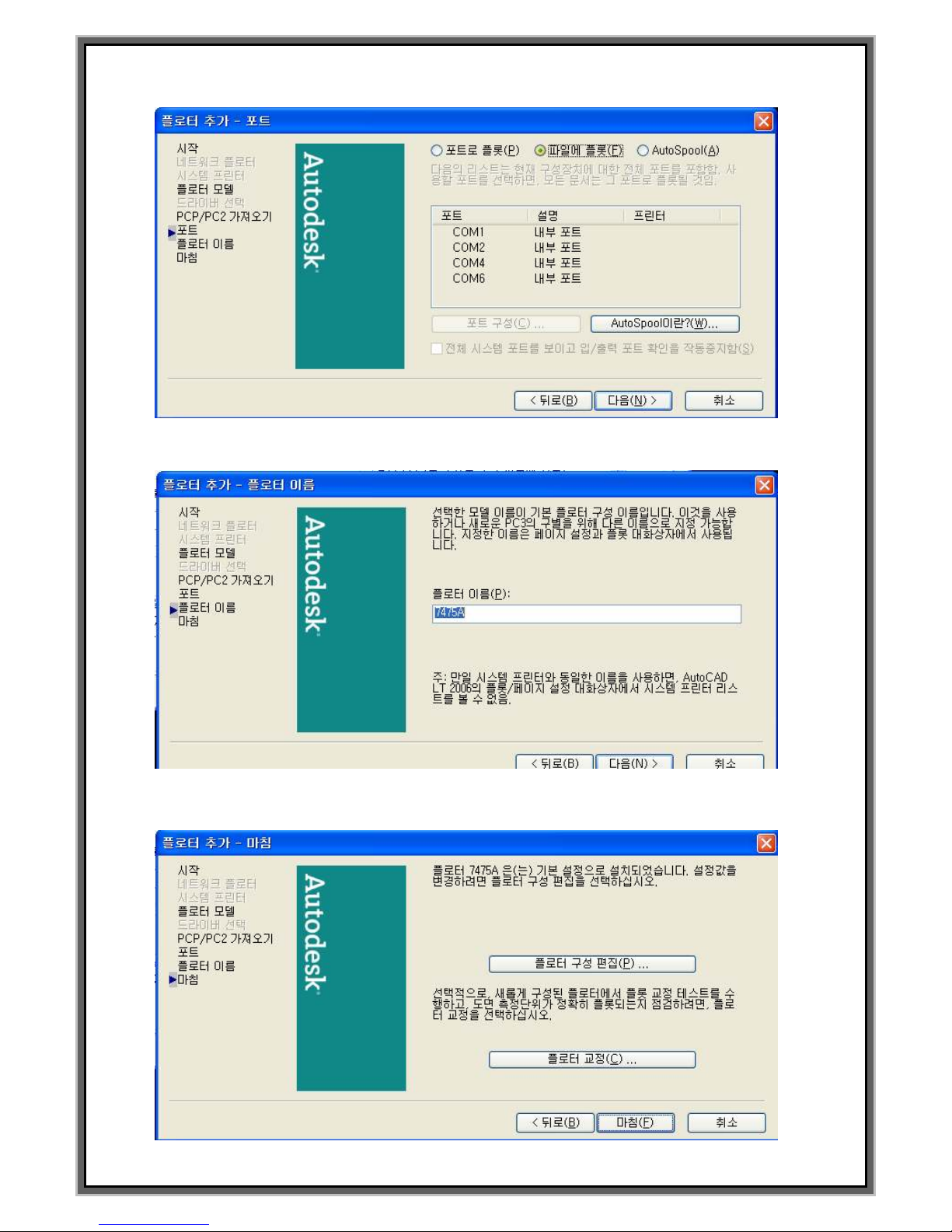
7. Select Plot(F) on file.
8. Set the name of plotter and click “Next” (N). Use dafault value 7475A.
9. Click Finish(F) after plotter configuration.
Page 63
63
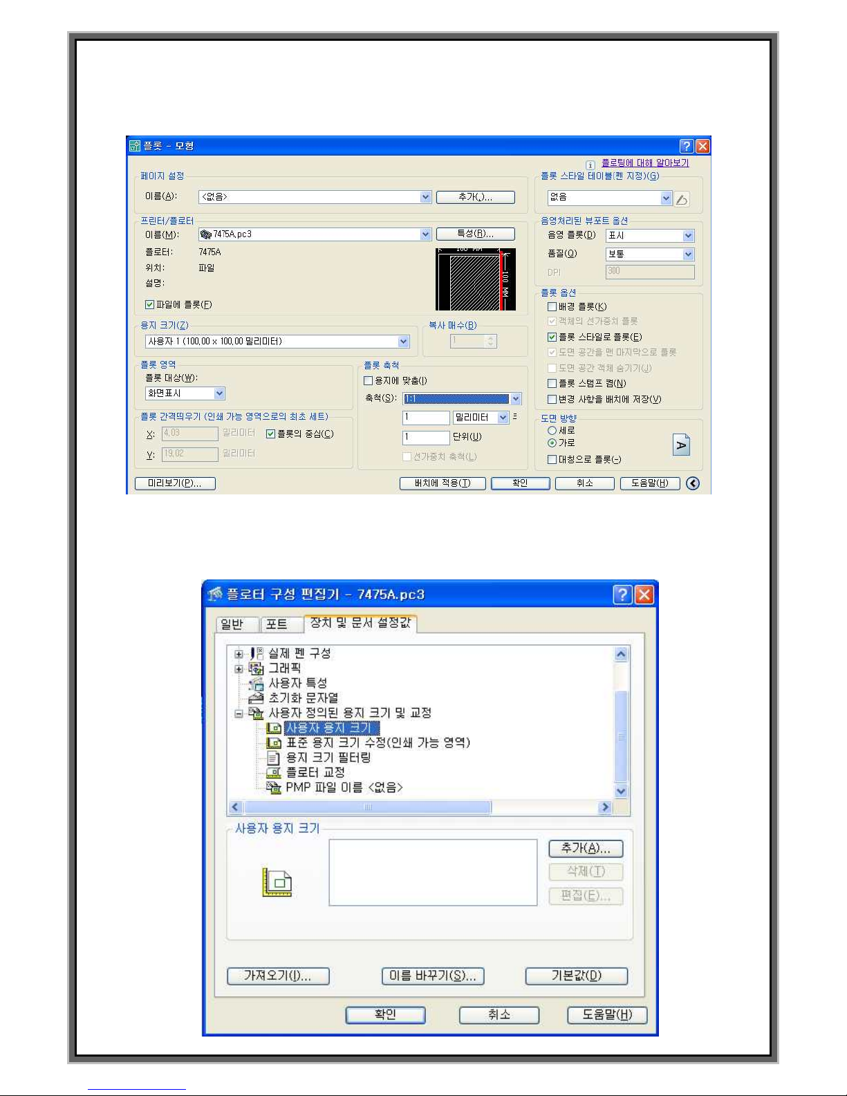
10. Below screen is indicated if PLOT setting window is opened by command word.
Select 7475A on Print and Plot configuration and then click Register(R).
11. Add the user`s paper size. Below screen is indicated if click paper size and click to Add.(A)
Page 64
64
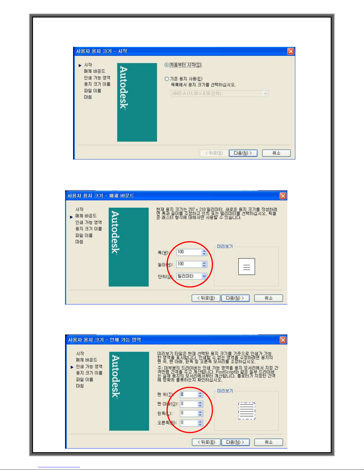
12. Select Start from scratch(S) if the below screen indicated and click “Next”(N).
13. Determine the paper size. Set the width and height to 100. Check the unit of it is mm.
Click to Next.(N)
14. Determine possible printing area. Set all value “0”. Click to Next.(N)
Page 65

65
15. Determine the size of user`s paper. In order to use default value,
do not modify and click :Next”(N).
16. Enter the file name of user paper size. In order to use default value,
do not modify and click :Next”(N).
17. Setting of new paper size is done. Click “Finished”(F).
Page 66
66
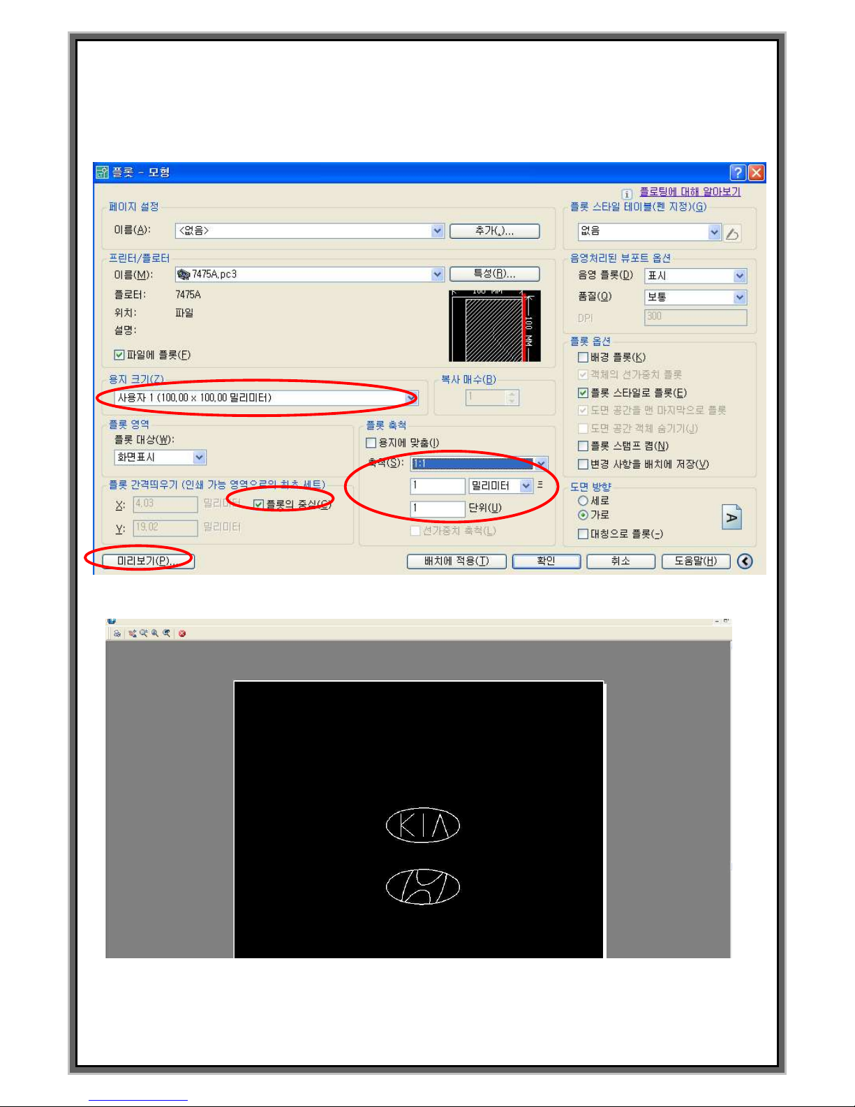
18. Select 7475A same as below and select the paper size 100 x 100 mm.
Set the scale 1:1. You may display of PLOT as screen display or select the window.
19. Plot which will be output is indicated same as below if click “Preview”(P).
20. Window which determine name of PLT file will be indicated if click PLOT button to the
upper left corner. Creating PLT file is done if click “Save”(S) after input the file name.
Page 67
67
MAINTENANCE
MAINTENANCE
Trouble Shooting
Backup and recovery of Marking data
Appendix
MARKING HEAD Assembly
PLC&I/O INTERFACE
ASCII CODE and DATA
Example of Input Auto marking DATA
How to change the motor
How to change the driver
◆ How to change CPU / IO board
◆ How to use JS-1000
◆ Edit marking block data and
modify the time of controller
Page 68
68
General maintenance
u Use the dry air without the high moisture
u Check the putting to earth ground
u Check the connection of connector
u Be careful of the trespass of paint, metal chip & dust into MCU
u Checking the exhaust fan & filter
u Increase of misprint, check in the pin assembly
Servicing the Marksman
When Marking machine doesn`t work :
Symptom
Checklist
The lamp on the front panel doesn`t ON
Check the electric of main power (100V – 220V)
All functions are working well but it doesn`t mark
after giving the start signal.
In case there`s the value to MARK UP
TO[00000000]on F2 (Refer to Pg11 F2 mode)
STATUS [ X-DRV. FAULT] Comes out
It is the problem of X-axis of Stepping driver or
motor. Or breaking of a wire for X-axis motor.
STATUS [Y-DRV. FAULT] Comes out
It is the problem of Y-axis of Stepping driver or
motor. Or breaking of a wire for Y-Axis motor.
STATUS [@G@>Input] Comes out
Entered data is less than set of digit when ASCII
code is input.
STATUS [@G@<Input] Comes out
Entered data is more than set of digit when ASCII
code is input..
STATUS [LIMIT ERROR] Comes out
Home sensor is detected during the marking.
-> Set the value of X and Y more than current
value.
Or check the direction of marking.(A:000)
If the LCD displays the misspell or the cursor moves by one self:
Symptom
Checklist
If the LCD displays the misspell or the cursor
moves by one self
If “Caps Lock” is ON on the keyboard, it may
malfunction.
In case letter on LCD is broken and doesn`t work
correctly.
In case there`s no letter on the LCD display
Please clear all memory on the front panel, and
input the data and start the machine again. Still
have a problem, please contact our distributor.
Page 69
69
When the location of marking data is changed :
Symptom
Checklist
Changed the location of marked data
Check the coordinate of X and Y. ( Unit of
coordinate is 0.1mm. Refer to Pg.12 F3 EDIT )
Check the tension of timing belt and PULLY
which are connected with X and Y axis stepping
motor. (Refer to Pg.82 )
Check the condition of customer parts which is
fixed up tightly.
Check the condition of marking pin whether it is
installed tightly or not.
Check the marking speed on the controller.
Refer to F5 mode(In case of PH pin : 2000 , In
case of LP pin: 1000)
When the Shape of letter is broken or marking pin doesn`t move:
Symptom
Checklist
When the letter is marked badly shaken
Check the tightness of timing belt and pully
which are connected with X and Y axis stepping
motor. ( Refer to Pg.82)
Check the parameter of stepping motor on F5
SETUP. (Refer to Pg.40 )
Check the condition of work-piece during the
marking. If the work-piece is moving during the
marking , marking result will be bad.
Check the connection of marking pin holder with
marking head.
Check the inside of marking pin holder whether
there is foreign substances or not
Marking pin doesn`t move to any direction
Check the connection of main cable.
Check the wiring of the steeping motor in the
marking head.
Check the tension of timing belt and pully in the
marking.
Check the condition of stepping motor and driver
in the controller.
When the first of letter is marked dim or isn`t
marked
Check the inside of marking pin holder whether
there is foreign substances or not.
Adjust the value of SOL.DN DLY[00002]upper a
little by a little.
Page 70
70
, When marking depth is not steady.
Symptom
Checklist
When marking depth is not steady
Clear marking pin holder and pin using
`WD40’cleaner. (Refer to Pg.43)
Set the air pressure of PH PIN between
4~4.5Kg/cm2
Set the air pressure of LP PIN between
1.5~2.5Kg/cm2
Set the distance between the tip of marking pin
and work piece properly..
PH PIN : App. 3 mm, LP PIN :App. 6 mm
In case the pin is moving but pin doesn`t mark
If press simulation key( F9, “S”on the
keyboard), it doesn`t mark .
Check the condition of sol.valve using “DEL”&
“INS” on the keyboard (Refer to Pg.47 F6 TEST
Check the inside of marking pin holder whether
there is foreign substances or not.
Moisture and oil is mixed to air, this kind of
problem can be happened.
Other check :
Symptom
Checklist
When the LED of 5V and 24V on front panel OFF
Check the condition of power supply in the
controller. There are two(5V, 24V) power supply
in the controller and check the condition through
green LED on it.
On F2 and F8, LED for Ready is OFF and when
the output doesn`t occur
When you turn the controller ON and OFF, Ready
signal doesn`t output until you press F11 or
give the reset signal using I/O
Pin comes out from pin holder without stroke.
Check the pin selector. You must set the pin
selection depending on the marking pin
Check the condition of So. Valve in the marking
head
Brightness of LCD is too dark or dim
Adjust the brightness of LCD using adjustable
resistance at the front panel of controller
In case air is leaking in the marking head.
Exchange the SOL. Valve in the marking head
Page 71
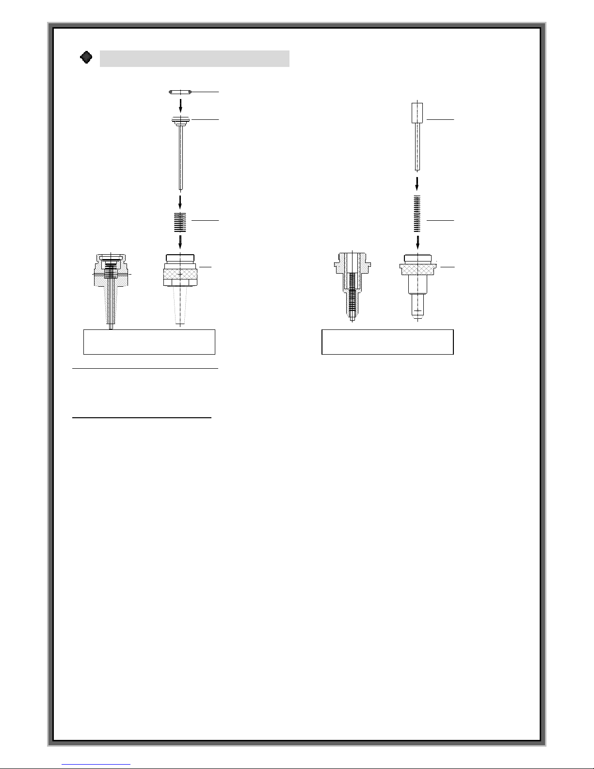
71
Maintenance of the marking pin:
PH16 조립도
LP10 조립도
PH16 분해도
LP10 분해도
O-RING
PH16 PIN
SPRING
PH16 PIN HOLDER
SPRING
LP10 PIN
LP10 PIN HOLDER
Disassembling & Assembling
1.Take out “O ring”and spring
2.Assembling is in the reverse order.
Cleaning of the marking pin
If the pin has some problem due to the metal chip, and water ,and dust ,please spray the cleaner
“WD40”into the pin and start the vibration test.
PH-16
LP-10
Page 72
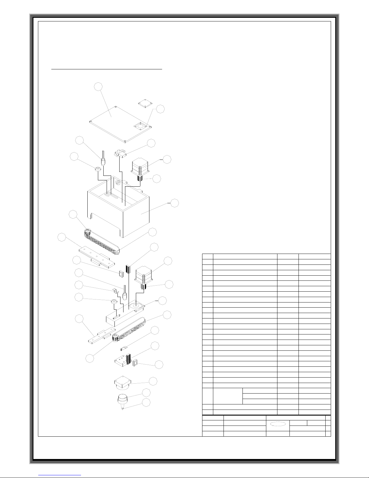
72
Marking Head Assembly
Rev.no
Description
Marking head assembly
헤드프레임
헤드커버
솔레노이드밸브
벨트 텐션 너트
핀홀더 블럭
벨트고정판
핀홀더
마킹핀
MK100-001
mat'l: n/a
date: Jan. 18 - 2000
Jeil MTECH Co.,
jmt
scale:full
dwg no.:
dwg by: OH HYUN TAE
PH-I6
LP-10
No.
Part description
Qty
Part no.
X-축 홈센서
Y-축 홈센서
X-축 LM 가이드
Y-축 LM 가이드
Y-축 프레임
X-축 풀리
Y-축 풀리
X-축 아이들 풀리
X-축 벨트
X-축 센서 감지판
Y-축 무빙 프레임
커넥터 홀
X-축 벨트 고정블럭
마킹헤드 구성도
14
10
8
1
11
3
5
2
27
6
13
15
16
24
25
22
17
23
9
4
12
lp-06
18
X축 모터 조립 앗세이
Y축 모터 조립 앗세이
Y-축 아이들 풀리
Y-축 벨트
7
19
20
벨트 텐션 너트
21
Y-축 센서 감지판
26
23
MK100-002
MK100-003
MK100-004
MK100-005
MK100-006
MK100-007
MK100-008
MK100-009
MK100-010
MK100-011
MK100-012
MK100-013
MK100-014
MK100-015
MK100-016
MK100-017
MK100-018
MK100-019
MK100-020
MK100-021
MK100-022
MK100-023
MK100-024
MK100-025
MK100-026
MK100-027
MK100-028
MK100-029
1
2
3
4
5
6
7
8
9
10
11
12
13
14
15
16
17
18
19
20
21
22
23
24
25
26
27
Page 73
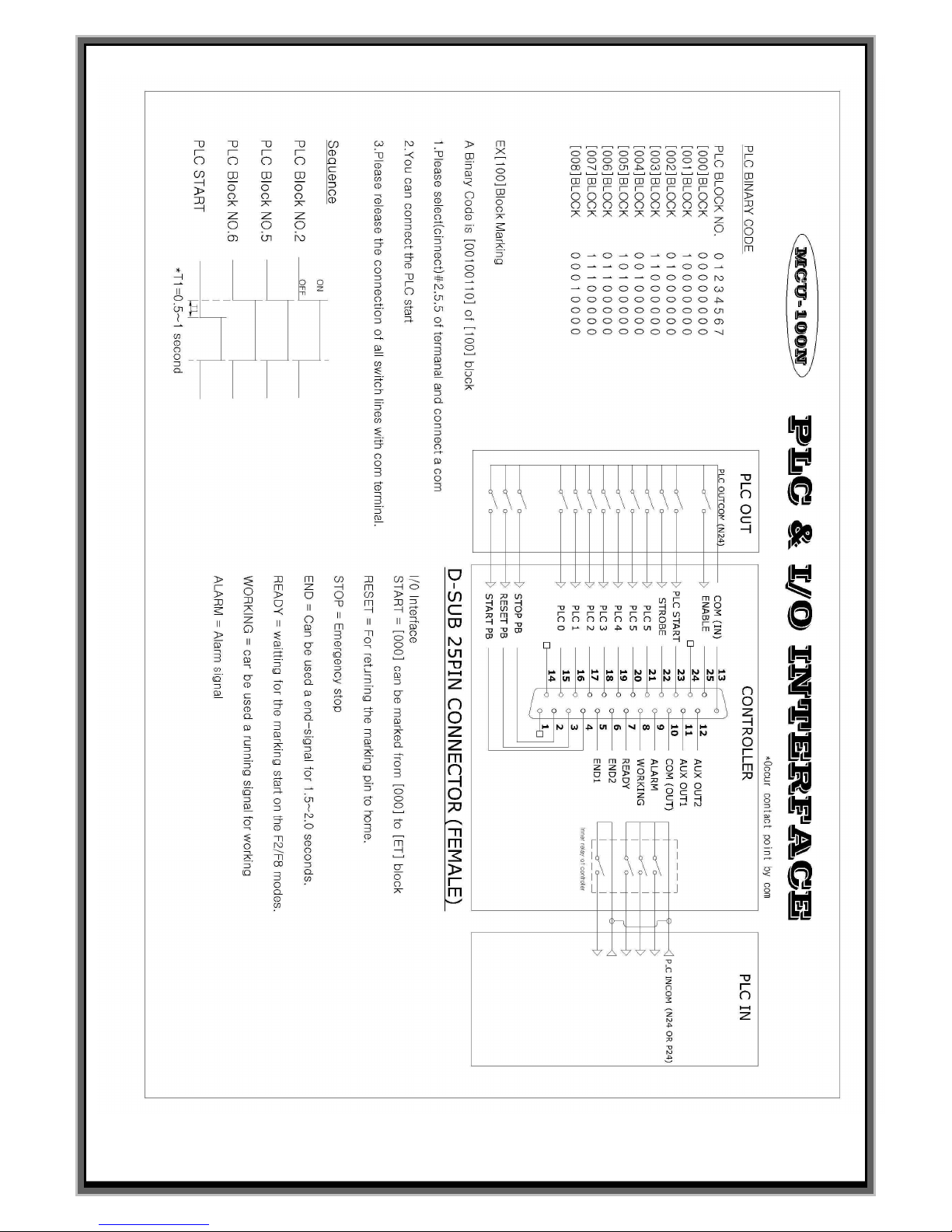
73
Page 74

74
** How to use ASCII code
How to make the data
@GGGGGG@
Set the no. of data using @G@ and then
transfer the data
And then transfer the data depending on no.
of@G@
Indicate the progressing of ASCII
CODE data
INP.CHAR, Digits
If transfer the ASCII CODE data to the
controller one by one, can see the number
which is counting in STATUS[ ]
Comparioson function of ASCII
CODE digits
@G@ > Input
No. of transffered data is more than the digits
in the controller. In this case, can not be
marked.
@G@ < Input
No. of transffered data is less than the digits in
the controller. In this case, can not be marked
Several line marking of ASCII CODE
Sequence block
In case you need the marking more than
2lines, should use Sequence block. Function
of Sequence is activated pressing F3F3 twice.
(Refer to Pg.34)
Example of sequence mode at ASCII
CODE
When you use
single block
(Standard)
S000//H /B000 / H
Giving PLC start signal, [000] is only marked
after transfer ASCII data
When you use 3
block
[000][001][002]
S000//B000//B001/B002/H
Giving PLC start signal without contact point,
[000][001][002] blocks are marked after
transfer ASCII data
In this case, you may not input “H” in front
ofS000
Start by ASCII CODE
PLC START
Can compare between the transferring and
setting data. Sequence mode has to be used
for several lines marking.
START
Common start signal. Although the transfered
data is lack or more, marking performed. In
case the data is not enough, it marks only
received data. Serveral line marking doesn`
need to use Sequence mode.
Page 75
75
ASCII Code
Decimal
no
Hexadecimal
no.
Binary no.
Octal
numeral
ASCII
Decimal
no
Hexadecimal
No.
Binary no.
Octal
Numeral
ASCII
0
1
2
3
4
5
6
7
8
9
10
11
12
13
14
15
16
17
18
19
20
21
22
23
24
25
26
27
28
29
30
31
32
33
34
35
36
0x00
0x01
0x02
0x03
0x04
0x05
0x06
0x07
0x08
0x09
0x0A
0x0B
0x0C
0x0D
0x0E
0x0F
0x10
0x11
0x12
0x13
0x14
0x15
0x16
0x17
0x18
0x19
0x1A
0x1B
0x1C
0x1D
0x1E
0x1F
0x20
0x21
0x22
0x23
0x24
0000 0000
0000 0001
0000 0010
0000 0011
0000 0100
0000 0101
0000 0110
0000 0111
0000 1000
0000 1001
0000 1010
0000 1011
0000 1100
0000 1101
0000 1110
0000 1111
0001 0000
0001 0001
0001 0010
0001 0011
0001 0100
0001 0101
0001 0110
0001 0111
0001 1000
0001 1001
0001 1010
0001 1011
0001 1100
0001 1101
0001 1110
0001 1111
0010 0000
0010 0001
0010 0010
0010 0011
0010 0100
000
001
002
003
004
005
006
007
010
011
012
013
014
015
016
017
020
021
022
023
024
025
026
027
030
031
032
033
034
035
036
037
040
041
042
043
044
NUL
SOH
STX
ETX
EOT
ENQ
ACK
BEL
BS
HT
LF
VT
FF
CR
SO
SI
DLE
DC1
DC2
DC3
DC4
NAK
SYN
ETB
CAN
EM
SUB
ESC
FS
GS
RS
US
SP
!
"
#
$
64
65
66
67
68
69
70
71
72
73
74
75
76
77
78
79
80
81
82
83
84
85
86
87
88
89
90
91
92
93
94
95
96
97
98
99
100
0x40
0x41
0x42
0x43
0x44
0x45
0x46
0x47
0x48
0x49
0x4A
0x4B
0x4C
0x4D
0x4E
0x4F
0x50
0x51
0x52
0x53
0x54
0x55
0x56
0x57
0x58
0x59
0x5A
0x5B
0x5C
0x5D
0x5E
0x5F
0x60
0x61
0x62
0x63
0x64
0100 0000
0100 0001
0100 0010
0100 0011
0100 0100
0100 0101
0100 0110
0100 0111
0100 1000
0100 1001
0100 1010
0100 1011
0100 1100
0100 1101
0100 1110
0100 1111
0101 0000
0101 0001
0101 0010
0101 0011
0101 0100
0101 0101
0101 0110
0101 0111
0101 1000
0101 1001
0101 1010
0101 1011
0101 1100
0101 1101
0101 1110
0101 1111
0110 0000
0110 0001
0110 0010
0110 0011
0110 0100
100
101
102
103
104
105
106
107
110
111
112
113
114
115
116
117
120
121
122
123
124
125
126
127
130
131
132
133
134
135
136
137
140
141
142
143
144
@
A
B
C
D
E
F
G
H
I
J
K
L
M
N
O
P
Q
R
S
T
U
V
W
X
Y
Z
[
\
]
^
_
`
a
b
c
d
Page 76

76
37
38
39
40
41
42
43
44
45
46
47
48
49
50
51
52
53
54
55
56
57
58
59
60
61
62
63
0x25
0x26
0x27
0x28
0x29
0x2A
0x2B
0x2C
0x2D
0x2E
0x2F
0x30
0x31
0x32
0x33
0x34
0x35
0x36
0x37
0x38
0x39
0x3A
0x3B
0x3C
0x3D
0x3E
0x3F
0010 0101
0010 0110
0010 0111
0010 1000
0010 1001
0010 1010
0010 1011
0010 1100
0010 1101
0010 1110
0010 1111
0011 0000
0011 0001
0011 0010
0011 0011
0011 0100
0011 0101
0011 0110
0011 0111
0011 1000
0011 1001
0011 1010
0011 1011
0011 1100
0011 1101
0011 1110
0011 1111
045
046
047
050
051
052
053
054
055
056
057
060
061
062
063
064
065
066
067
070
071
072
073
074
075
076
077
%
&
'
(
)
*
+
,
-
.
/
0
1
2
3
4
5
6
7
8
9
:
;
<
=
>
?
101
102
103
104
105
106
107
108
109
110
111
112
113
114
115
116
117
118
119
120
121
122
123
124
125
126
127
0x65
0x66
0x67
0x68
0x69
0x6A
0x6B
0x6C
0x6D
0x6E
0x6F
0x70
0x71
0x72
0x73
0x74
0x75
0x76
0x77
0x78
0x79
0x7A
0x7B
0x7C
0x7D
0x7E
0x7F
0110 0101
0110 0110
0110 0111
0110 1000
0110 1001
0110 1010
0110 1011
0110 1100
0110 1101
0110 1110
0110 1111
0111 0000
0111 0001
0111 0010
0111 0011
0111 0100
0111 0101
0111 0110
0111 0111
0111 1000
0111 1001
0111 1010
0111 1011
0111 1100
0111 1101
0111 1110
0111 1111
145
146
147
150
151
152
153
154
155
156
157
160
161
162
163
164
165
166
167
170
171
172
173
174
175
176
177
e
f
g
h
i
j
k
l
m
n
o
p
q
r
s
t
u
v
w
x
y
z
{
|
}
~
DEL
Page 77

77
Advance Programming
INPUT
MARKING
Letter & symbol marking
12ABab!%
12ABab!%
Auto serial numbering
(Variable = @L@)
I = +1 @LLLL@
I = +2 @LLLL@
I = -1 @LLLL@
1000->1001->1002
1000->1002->1004
1000->0999->0998
Auto serial numbering using
all letter & numbering
(Variable = @A@)
I = +1 ,
L = 00000000,
@AAA@0
AAA->AAB->AAC
Calendar code marking
Z:Year code N: Month code
E: Day code
@ZNE@
ABM
Calendar marking
Y: Year
M: Month
D: Day
Ex :02.13.2008
@YYMMDD@
@YYYYMMDD@
@YY@/@MM@/@DD@
080213
20080213
08/02/13
Hour/minute/second Marking
H: Hour B: minute S: second
18:21:53
@HHBBSS@
182153
A team of worker-marking
(Variable = @O@)
Current time is 18:21:53
Input @O@ ,
B
[B]08:30:00 ~ 20:30:00
[A]20:30:01 ~ 08:29:59
Lot no. Auto reset function
(Team code reset = @R1@)
(Daily reset = @R2@)
(Weekly reset셋 = @R3@)
(Monthly Reset = @R4@)
@LLLR1@
Team Reset
@LLLR2@
Reset on every 0 o`clock
@LLLR3@
Resent on Sunday 0 o`clock
@LLLR4@
Reset on every 1st 0 o`clock
Barcode marking
(Variable = @K@)
@KKKKK@
(Set K depending on no. of
barcode)
Reading data which is scanned by
scanner is marked
ASCII CODE marking
(Variable = @G@)
@GGGGG@
(Set the no. of data )
Transferred data is marked.
JULIAN CALENDER
From 1 to 365
(Variable = @J@)
It is Feb.13th.2008 now
@JJJ@
044
Week code marking
(Variable @CC@)
It is Feb.13th.2008 now
@CC@
07
Page 78

78
**Application of marking automatic variable****
*** The letters which are between each ‘@’ are recognized as marking variable.
Ex.) In case of @YYYY@ ,
Marking machine mark the current year ‘2013’ ,
In case of @YY@YY ,
Last 2 no. of current year and YY letters are marked like ‘08YY’.
*** Marking variable can be combined through only 1 times ‘@ ~ @’.
Ex.) In case of using Year/Month/day/work code
@Z@@N@@E@@O@ (O) -> @ZNEO@ (O)
Ex.) Year/Month/Day/Hour/Minute/Second marking
@YYYYMMDDHHBBSS@
Ex.) Serial no. + ASCII code
@LLL@@GGG@ (O) -> @LLLGGG@ (O)
Julian calendar and serial no. which are required continuous no. can not be marked separately.
Ex.) Serial no.
@L@@L@@L@ (X) -> @LLL@ (O)
Julian Calendar
@J@@J@@J@ (X) -> @JJJ@ (O)
*** Example of variable combination )
It is at 11:59:10 in Dec.31st 2013,
Input : @YYYY@/@MM@/@DD@_@HH@:@BB@:@SS@
Marking : 2013/12/31_11:59:10
*** In case using auto reset function for serial no., @~@ can be used 1 time.
Ex.) Year, month, day + Serial no. + Monthly reset
@YYMMDD@/@LLL@/@R@ (X) -> @YYMMDDLLLR4@ (O)
Page 79

79
Page 80
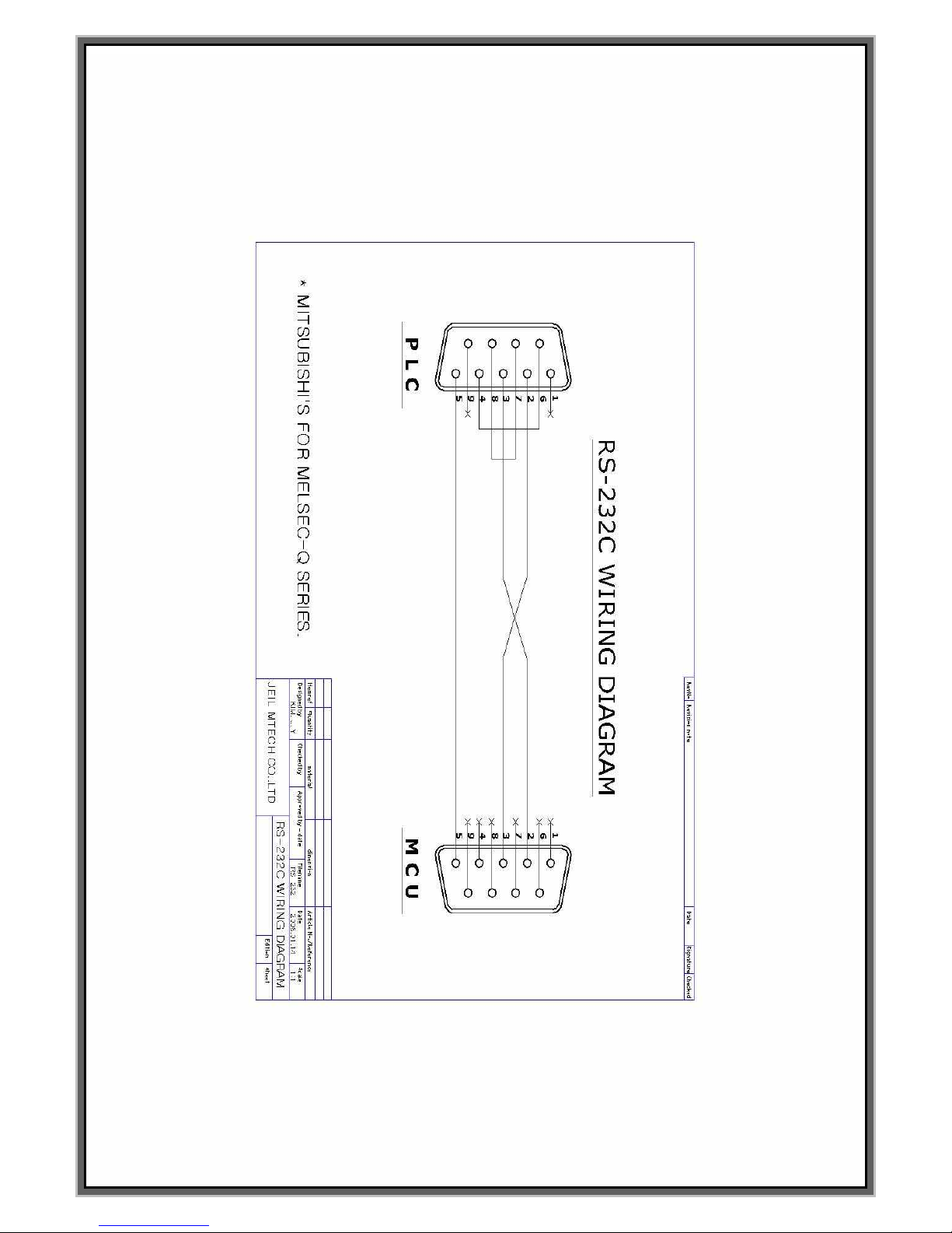
80
Page 81
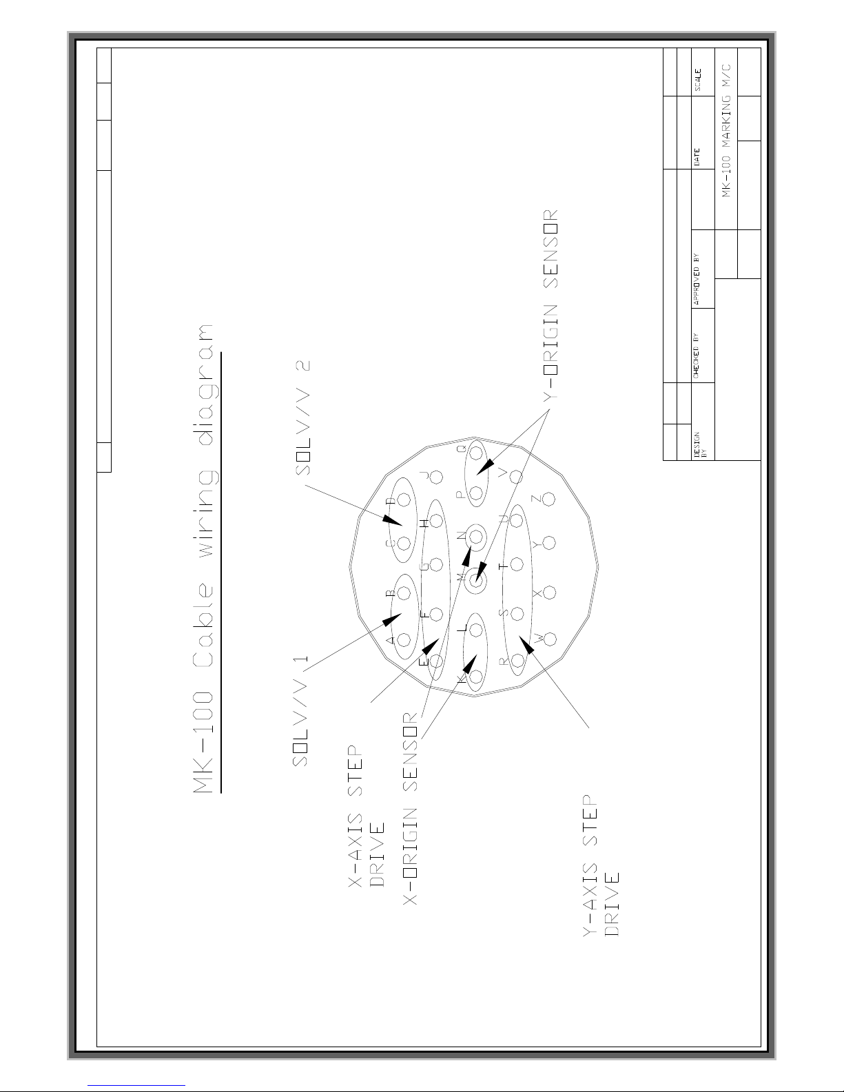
81
etc
Sheet
material
O
MODEL
DWG NO.
Description
item Quantity
오 현태
JEIL MTECH CO.,LTD
2003,2,13
Edition
MCU-100D
Page 82

82
How to change stepping motor
1. Open the marking head by tool.
2. Disconnect the connector of motor in the marking head .
Page 83
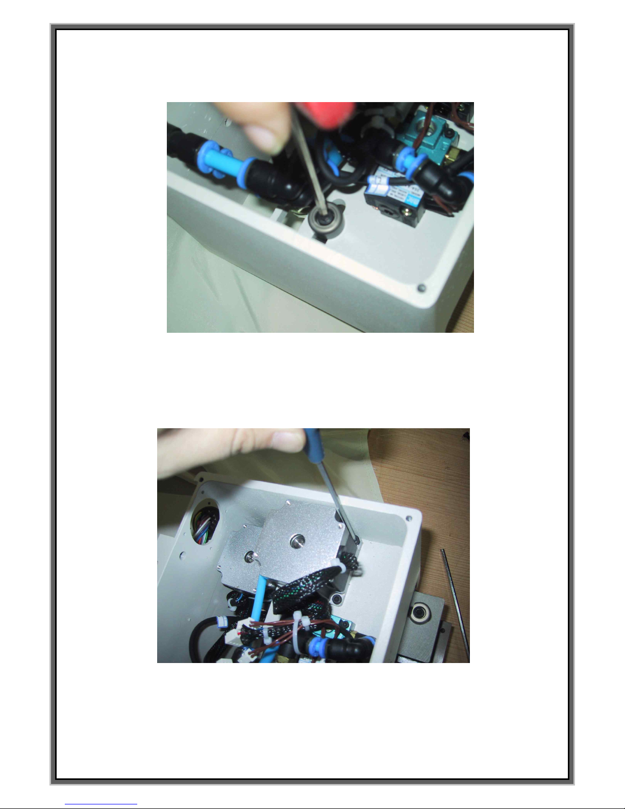
83
3. After disconnected the connector of motor, loosen a nut.
4. Loosen 4 pcs of hexagon head bolt which fix the stepping motor.
Page 84
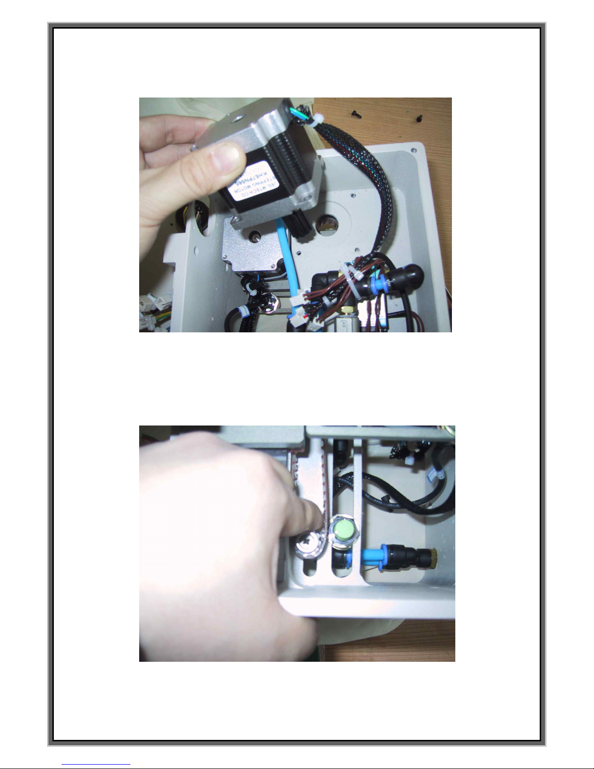
84
5. Take out the motor and install new motor to the marking head.
6. Push the Pully to opposite side to adjust the tension of timing belt.
Page 85
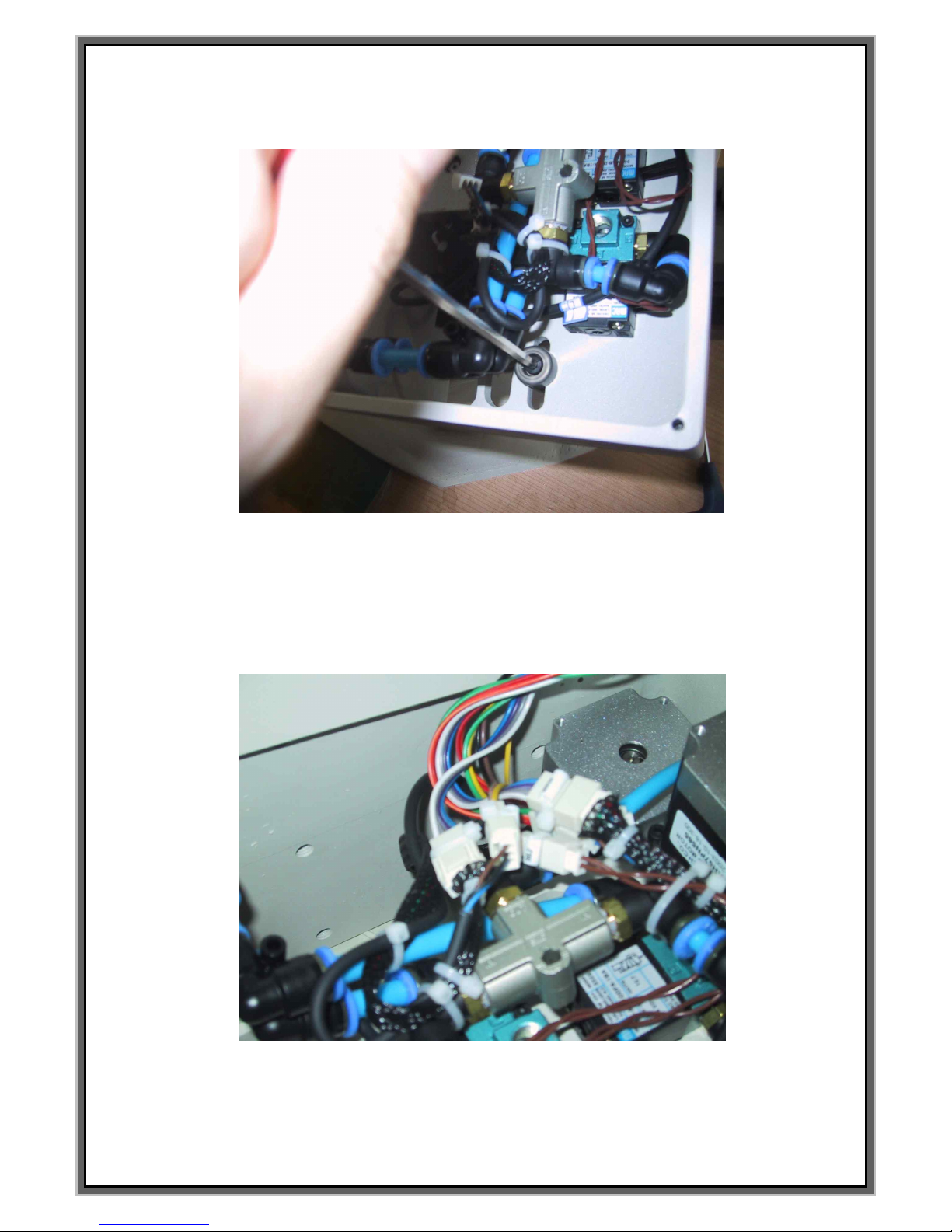
85
7. Check the tension of the timing belt and then tighten up the nut of Pully..
8. Connect the connector 1 by 1 according to the no.
and cover the upper plate of marking head.
Page 86
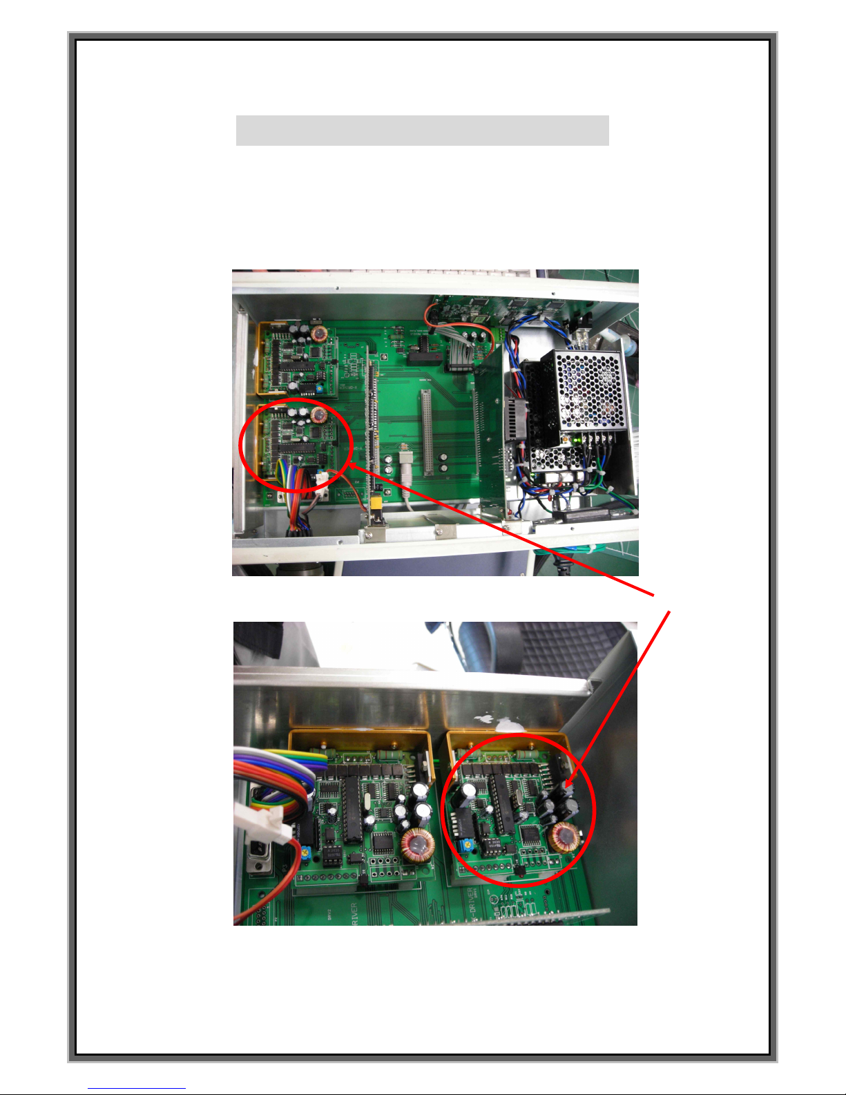
86
How to change the stepping driver
1. Loosen the screws of the controller to open it.
2. Indicated Red circle is Stepping driver..
3. Above is the pictures of Micro=-stepping driver.
Page 87
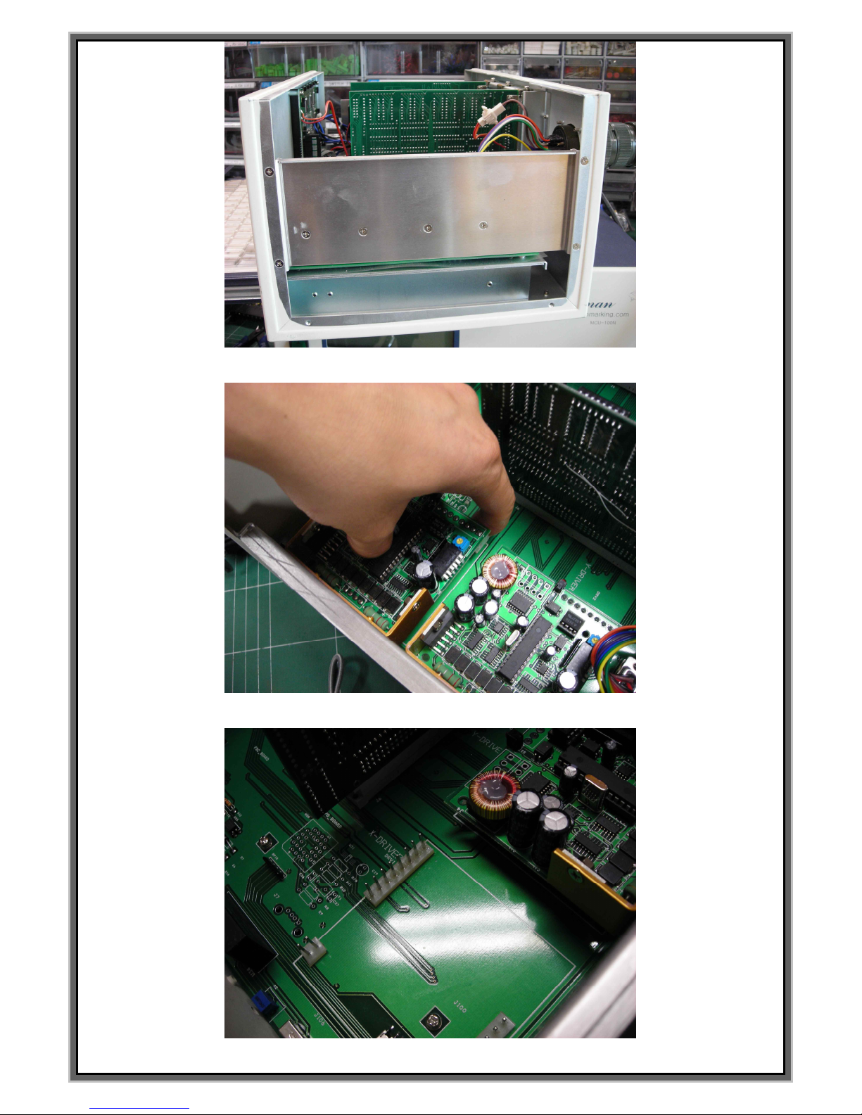
87
4. Loosen 4 screws which are in the center in the pictures.
5. Can separate the stepping driver if you pick it up after loosen the screws .
6. Specification of stepping drivers for both axis are same each other.
Page 88
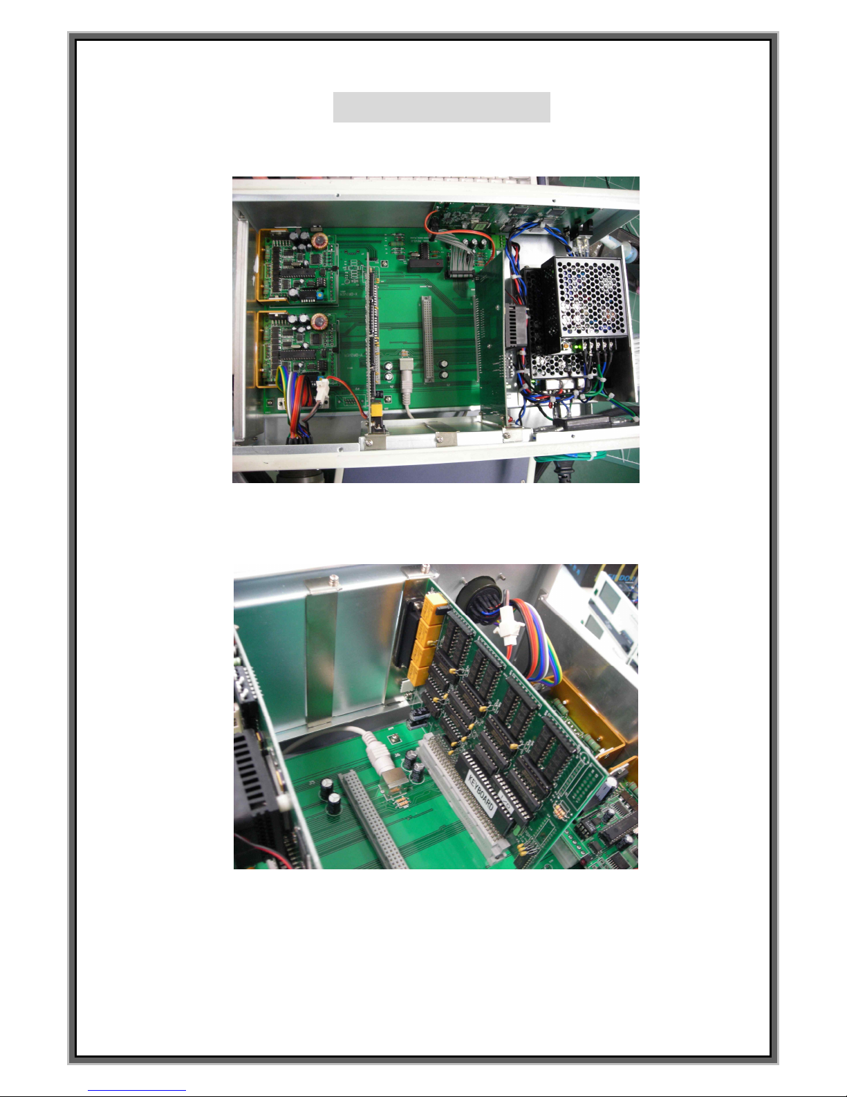
88
How to change I/O
1. Loosen the screws of the controller to open it.
2. Can see the I/O board which is located next to stepping driver.
3. Loosen the screw which is support I/O board and then pick it up .
4. After replacement, you must put I/O board to base board fit properly
5. The way to change the CPU board as same as above. CPU board is located next to the I/O board..
6.
Page 89
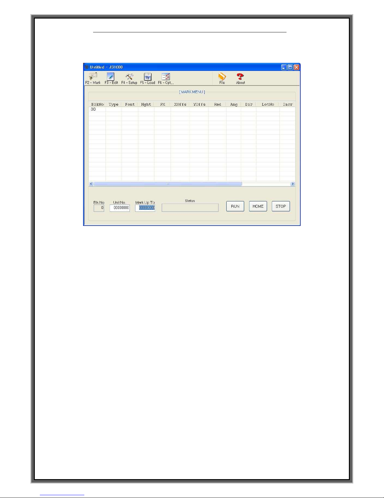
89
JS-1000V 4.0 Marking Program construction
<<F2 MARK MENU>>
1. Function of ICON on the top of screen are as following .
- F2 Mark : Can give START, STOP , RESET signal to the controller.
- F3 Edit : Modify the data and import saved data on the s/w.
- F4 Setup : Adjust the step of motor and timing of sol. valve..
- F5 Load : Can load PLT file and USER font to the controller.
- F6 Option : Can select the port of JS_1000 S/W and single and multi block.
Comport no. between the P.C and S/W must be always same
- File : Can save and import marking data.
- About : Information of JS_1000 S/W.
2. Function of ICON on the bottom of screen are as following.
- Blk No : Block No..
- Unit No : Marking quantity .
- Mark Up To : Indicates the no. of specify quantity marking.
- Status : Status of marking machine.
- RUN : Start signal for marking.
- HOME : Return to home position.
- STOP : Emergency stop.
3. Marking data is indicated in the middle of screen.
Can not modify the data on this screen.
Page 90
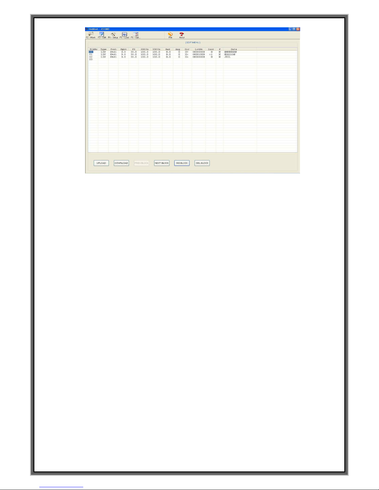
90
<<F3 EDIT MENU>>
1. Above picture is as following.
- BlkNo : Block no.. 00 is single block and 00.00 is multi block.
- Type : Select the marking type.
- Font : Select the font.
- Hght : Select the height of letters.
- Px : Adjust the distance between the center of each letters.
- Xoffs : Location of X-axis which the marking starts.
- Yoffs : Location of X-axis which the marking starts.
- Rad : In case of circular marking. Set the size of circle.
- Ang : Marking direction of the letter in case of linear marking /
In case of circular marking, set the start point of the marking on the circle
- Dir : Set the marking direction. (0~359º)
- LotNo : Set the first no. of Serial no.
- Incr : Creation increase and decrease of serial number.
- P : Pause
- Data : Marking data
2. The function of the buttons which are in the bottom on the screen is as following.
- UPLOAD (MCU -> PC) : Import block data from MCU. ( Backup features)
- DOWNLOAD (PC -> MCU) : Save current data to the MCU. ( Recovery capabilities )
**Caution – In case click “DOWNLOAD” when there`s no marking data,
empty data is transferred to the MCU. It is the same function of MEMORY CLEAR.
- PREV BLOCK : Select the previous block.
- NEXT BLOCK : Select the next block .
- INS BLOCK : Insert new block .
- DEL BLOCK : Delete the selected block.
Page 91
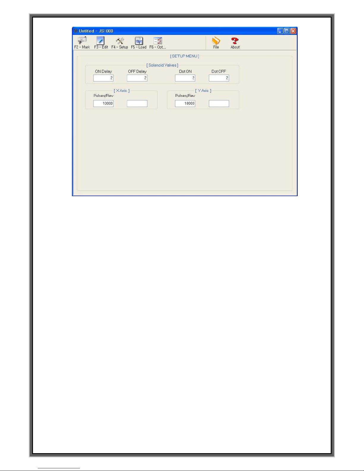
91
<<F4 SETUP>>
1. Solenoid Valves
- ON Delay : The delay time of sol. Valve when the marking is started.
- OFF Delay : The delay time of sol. Valve when the marking is finished.
- Dot ON : After arrive marking position, activate Sol. Valve work set amount time.
- Dot OFF : The time of moving upto the marking location at DOT font.
2. X Axis
- Pulses/Rev : no. of Purse for stepping motor which rotates 1cycle.
3. Y Axis
– Pulses/Rev : no. of Purse for stepping motor which rotates 1cycle.
Page 92

92
<< F5 Load >>
1. User1 ~ User4
- Loading USER font. Can load user font if click Browse.
2. User5 ~ User10 : The function we don`t use..
3. Plot1 ~ Plot4
- Loading PLOT file which user created. Can load PLOT file if click Browse
4. Plot5 : The function we don`t use.
Page 93

93
<< F6 Option >>
1. COM Port : Set the CORPORT of the S/W.
COMPORT between P.C and JS-1000 S/W must be the same all the time.
2. Multi Line : Check on the “Multi line”when you use Multi block.
3. Lines/Block : Block no. which is indicated.
Page 94

94
How to Modify the data of
block
and
modify the time of the
controller
Page 95

95
How to modify the data of block
1. Open the keyboard drawer to the bottom of controller.
2. Below screen is indicated if press F3 on the keyboard.
3. Check the location of cursor. Can move the cursor if press ENTER key on the keyboard.
4. Can move the block no. through arrow key(↓ , ↑) on the keyboard in case of single block.
Can move first 2 block no. through PgDn, PgUp on the keyboard and last 2 block no. through arrow key
In case of multi block. Ex.: [00.00]
*In case of single block, block no. is indicated BLK NO.[000],
In case of Multi block, block no. is indicated BLK NO.[00.00].*
5. In case indicating the < NO BLOCK DATA > on the BLK NO[001] same as above pictures,
press “SPACE BAR” on the keyboard to activate
6. [EDIT CHA. Size] Press ENTER on the keyboard and input the value that you want. [Unit : 0.1 mm]
7. [EDIT the distance between the center of each cha.] Press Enter on the keyboard and
input the value that you want [Unit : 0.1 mm]
8. [EDIT the marking location] Press Enter on the Keyboard and input the value of X:0000 and Y:0000
9. [SELECT FONT] Press Enter on the Keyboard and then move to FNT:STD1.
Press SPACE BAR to change the FONT
FONTS are changed as following whenever press SPACE BAR STD1 -> STD2 -> DOT -> USER1 -> USER2
-> USER3 -> USER4
10. [EDIT Serial no.]Press Enter on the keyboard to move L:00000000.
And then input the serial number.
11. [EDIT Marking DATA] Press Enter on the Keyboard to move <DATA> on the screen.
Then type the marking data.
12. Press F2 if the change has been completed all.
**On RS-232 communication mode, set the controller at [F8] Communication mode**
F1 : M_MENU F2 : A_MARK F3 : EDIT F4 : FILE
F5 : SETUP F6 : TEST F7 : LOAD F8 : COMM
BLK NO. [ 000 ]
LN X : 0300 Y : 0300 A : 000
FNT : STD1 CH:030 PX:030 L:00000000 I:+1
<DATA> PAUSE : N
JEIL MTECH
[EDIT MODE]
BLK_COPY : CTRL_C BLK_MOVE : UP/DOWN
CURSOR_MOVE : ENTER SELECT : SPACE_BAR
BLK NO. [ 001 ]
EMT
< NO BLOCK DATA >
Page 96
96
How to modify the time of controller
1. Press F6 on the keyboard .
F1 : M_MENU F2 : A_MARK F3 : EDIT F4 : FILE
F5 : SETUP F6 : TEST F7 : LOAD F8 : COMM
X_HOME X_LIMIT Y_HOME Y_LIMIT
[ TEST MODE]
DATE_SET : Yy Mm Dd TIME_SET : Hh Bb Ss
2011/ 02/ 14 12: 45: 45
SENSOR [OFF] [OFF] [OFF] [OFF]
SOL. VALVE1: [OFF] SOL.VALVE2: [OFF]
SOL. ON : DEL_KEY SOL. OFF :INS_KEY
X POSITION = 20.00mm.
Y POSITION = 20.00mm.
2. Press the keys which can change the time on the above screen.
3. [Modification of Year] In case modify the year, 2011 will be changed 2021 if press capital letter “Y”
2011 will be changed 2012 if press lower case letter “y”.
4. [Modification of Month] In case modify the month. 02 will be changed 12 if press capital letter”M”.
02 will be changed 03 if press lower case letter “y”.
5. [Modification of Date] In case modify the date, 14 will be changed 24 if press capital letter”D”.
14 will be changed 15 if press lower case letter “d”.
6. [Modification of Hour] In case modify the hour, 12 will be changed 22 if press capital letter”H”
12 will be changed 13 if press lower case letter “h”.
7. [Modification of Minute] ] In case modify the minute, 45 will be changed 55 if press capital letter ”B”
45 will be changed 46 if press lower case letter “b”.
8. [Modification of Second] In case modify the second, 45 will be changed 55 if press capital letter ”S”
12 will be changed 13 if press lower case letter “s”.
9. Press F2 if all setting value is changed for marking.
**In case of communication mode by RS-232, press [F8] Communication mode.
Page 97

97
Bank-up the data to the SD card
1. Press [F4] six times on the keyboard to move below screen.
F1 : M_MENU F2 : A_MARK F3 : EDIT F4 : FILE
F5 : SETUP F6 : TEST F7 : LOAD F8 : COMM
FILE NAME [ ]
STATUS [ ]
[ALL SETUP SAVE]
F4 : MARKING DATA LOAD
FILENAME DATA TIME
>< NO FILE >
2. Input the file name that you want using keyboard when the cursor is in FILE NAME [ ] and then
press “Enter”to save. Can see the data on the STATUS[ ].
(File name can be saved is an 8 digit which is the combination of alphabetic and numeric.)
3. [SAVE DATA OK] is indicated on the STATUS[ ] if the back is done.
4. Press F2 if all setting value are changed for marking.
**In case of communication mode by RS-232, press [F8] Communication mode **
How to recover the data using SD card
1. Press [F4] five times on the keyboard to move below screen.
F1 : M_MENU F2 : A_MARK F3 : EDIT F4 : FILE
F5 : SETUP F6 : TEST F7 : LOAD F8 : COMM
FILE NAME [ ]
STATUS [ ]
[ALL SETUP LOAD]
F4 : SEQUENCE DATA SAVE
FILENAME DATA TIME
>< NO FILE >
2. Indicated the file which is in SD card to “>< NO FILE >” if press direction Key[↓]
on the keyboard at above screen.
3. Select the file which you want and click “Enter” on the keyboard to recover the data.
4. [LOAD DATA OK] is indicated on the STATUS[ ] if the data recover is done.
5. Press F2 if all setting value are changed for marking.
**In case of communication mode by RS-232, press [F8] Communication mode ****
Page 98
98
How to change worker`s time and team code
1. Press [F5] two times on the keyboard to move below screen.
F1 : M_MENU F2 : A_MARK F3 : EDIT F4 : FILE
F5 : SETUP F6 : TEST F7 : LOAD F8 : COMM
TEAM CODE
[ DATE CODE SET ]
CUSOR_MOVE : ENTER F5 : MOTOR/OPTIONS
1.[ A ] = FROM [08:00:00] TO [20:29:59]
2.[ B ] = FROM [20:30:00] TO [07:59:59]
3.[ ] = NO 3TH SHIFT
4.[ ] = NO 4TH SHIFT
5.[ ] = NO 5TH SHIFT
6.[ ] = NO 6TH SHIFT
7.[ ] = NO 7TH SHIFT
8.[ ] = NO 8TH SHIFT
2. Initial location of the cursor is [A] which is located to the below of TEAM CODE.
3. Set the team code of no. 1.
4. Select the team code of no.2 .
5. Put the cursor to the Team code and press Space bar if there`s team code and times is setting.
3shifts is changed to 2 shift.
6. Set the starting time of a day shift to [00:00:00]at FROM [08:00:00].
7. Set the starting time of a night-shift worker [12:00:00] at FROM [20:30:00].
** The reason why we set the time like above is Team code has to be set according to the date.
Therefore you should set the time of controller -08:00:00. ** (Refer to F5 mode)
6. Press F2 if all setting value are changed for marking.
**In case of communication mode by RS-232, press [F8] Communication mode **
Page 99
99
How to change the date
8. Below screen is indicated if keep press Enter key after press [F5] two times on the keyboard.
F1 : M_MENU F2 : A_MARK F3 : EDIT F4 : FILE
F5 : SETUP F6 : TEST F7 : LOAD F8 : COMM
YEAR CODE
[ DATE CODE SET ]
Y05[ A ] Y06[ B ] Y07[ C ] Y08[ D ] Y09[ E ]
Y10[ F ] Y11[ G ] Y12[ H ] Y13[ I ] Y14[ J ]
MONTH CODE
JAN [ 1 ] FEB [ 2 ] MAR [ 3 ] APR [ 4 ] MAY [ 5 ] JUNE [ 6 ]
JUL [ 7 ] AUG [ 8 ] SEP [ 9 ] OCT [ X ] NOV [ Y ] DEC [ Z ]
DATE CODE 1[A] 2[B] 3[C]
4 [D] 5[E] 6[F] 7[G] 8[H] 9[I] 10[J]
11[K] 12[L] 13[M] 14[N] 15[O] 16[P] 17[Q]
18[R] 19[S] 20[T] 21[U] 22[V] 23[W] 24[X]
25[Y] 26[Z] 27[1] 28[2] 29[3] 30[4] 31[5]
9. In case using the date code, Y05[A] is the code when is 2005.
10. Y11[G] is the letter in case 2011 is marked by letters.
11. To move the cursor, press [ENTER].
** Marking result of date code on above screen.
In case of May 6th 2011, it is marked “G5F”. **
12. Press F2 if all setting value are changed for marking.
**In case of communication mode by RS-232, press [F8] Communication mode **
 Loading...