

Page 1

For Technical Assistance, please call (800) 638-3600,
or visit www.magnadyne.com
Installation
Manual
Model: M9A
This device complies with part 15 of the FCC rules. Operation is subject to the following two conditions:
(1) This device may not cause harmful interference; and
(2) This device must accept any interference received, including interference that may cause undesired operation.
Note: The manufacturer is not responsible for any radio or TV interference caused by unauthorized modifications to
this equipment. Such modifications could void the user’s authority to operate the equipment.
Page 2

2
Installer Warnings!
This remote starter with alarm system is designed to be installed on fuel injected vehicles with an automatic
transmission ONLY.
• Do not plug the 8-pin or 5-pin wire harness into the alarm control module before you begin installing the
alarm. The wire harnesses must be plugged into the alarm control module after all connections are made.
Failure to follow this procedure could cause some confusion with transmitter operation and or alarm function
operation.
• Never install this remote starter on a manual transmission vehicle.
• This system must be installed and wired through a safety switch so it will not start in any forward or reverse
gear.
• Some automatic transmission vehicles (mainly older GM vehicles with a purple starter wire) have a
mechanical-type park safety switch instead of electrical safety switch. The mechanical type does not interrupt
the starter circuit when the transmission is any gear and does not offer the 100% level of safety required for
remote starting purposes. Therefore, our system should never be installed on any vehicle that uses a
mechanical type park safety switch.
• Once you install this system, you must verify that the vehicle will not start in any forward or reverse gear.
Regardless of the type of vehicle.
• Read operation manual for operating and programming routine.
• Do not install any component near the brake, gas pedal or steering linkage.
• Some vehicles have a factory installed transponder immobilizer system that can severely complicate the
installation. There is possibility that this system can not be installed on some immobilizer equipped vehicles.
• Most vehicles have an SRS air bag system. Use extreme care and do not probe any wires of the SRS system.
• Disconnect the car battery before connecting work on the vehicle.
• Use conventional crimp lock, bullet on any wiring. Poor wiring, i.e. taped joints will possibly introduce
unreliability into the alarm system and may result in false alarms or incorrect operation.
• Install wiring neatly under carpets or behind trim to prevent possible damage to wires.
• For the wires that operate at currents more than 10A, we suggest soldering all connection points. Do not use
crimp lock type connectors or wire nuts.
Component Installation . . . . . . . . . . . . . . . . . . . . . . . . . . . . . . . . . . . . . . . . . . . . . . . . . . . . . . . . . . . . . 3
Wiring . . . . . . . . . . . . . . . . . . . . . . . . . . . . . . . . . . . . . . . . . . . . . . . . . . . . . . . . . . . . . . . . . . . . . . . . 3-16
Programming the Transmitter . . . . . . . . . . . . . . . . . . . . . . . . . . . . . . . . . . . . . . . . . . . . . . . . . . . . . . . 17
Alarm Feature Programming . . . . . . . . . . . . . . . . . . . . . . . . . . . . . . . . . . . . . . . . . . . . . . . . . . . . . . 18-20
Remote Start Operation/ Programming . . . . . . . . . . . . . . . . . . . . . . . . . . . . . . . . . . . . . . . . . . . . . . 21-27
Speciality Features and Testing . . . . . . . . . . . . . . . . . . . . . . . . . . . . . . . . . . . . . . . . . . . . . . . . . . . 28-33
Wiring Diagram . . . . . . . . . . . . . . . . . . . . . . . . . . . . . . . . . . . . . . . . . . . . . . . . . . . . . . . . . . . . . . . . 34
Contents
Page 3
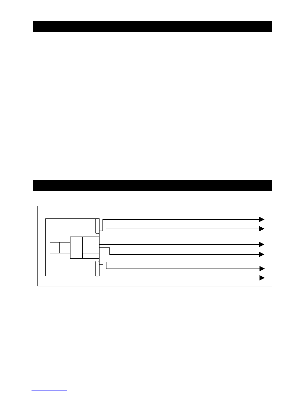
Windshield Receiver/Antenna
• The combination windshield receiver/antenna mounts on the windshield (inside vehicle).
• We suggest you mount the receiver/antenna on the lower left-hand side of the windshield.
Warning! Do not mount the Windshield Receiver/Antenna in such a manner that it obstructs
the driver’s view.
• The receiver/antenna can be mounted vertical or horizontal.
• Remove the protective tape backing.
• Carefully align the receiver/antenna and apply to windshield.
• Route the black connecting cable behind the trim and connect to receiver/antenna.
• Connect the other end to the control module.
Valet Switch
Select a mounting location for the switch that is easily accessible to the driver of the vehicle. The switch does
not have to be concealed. However, concealing the switch is always recommended, as this provides an even
higher level of security to the vehicle. Mount the valet switch in a hidden but accessible location. Route the
valet switch wires to the control module.
LED Status Indicator
The LED status indicator should be mounted in a highly visible area. Leave at least 6mm of space behind the
mounting location for LED housing. Once a suitable location is chosen, drill a 1/4" hole. Run the LED wires
through the hole then press the 2-pin LED housing into the place. Route the LED wires to the control module.
Wiring
3
Component Installation
Red Wire +12 V Input (Battery)
Red Wire +12 V Input (Battery)
Yellow Wire Ignition 1 Output (Must Connect)
Brown Wire ACC / Heater Output
Violet Wire Starter Output
Pink Wire Ignition 2 Output
White 6-Pin Heavy Gauge Connector
The method that the remote starter uses to start the vehicle is a duplicate of the ignition switch function. Below, is
an explanation of the 3 basic functions of the ignition switch. Since this installation will require analysis of the
ignition switch functions, it is recommended making the three connections below at the ignition switch harness
directly.
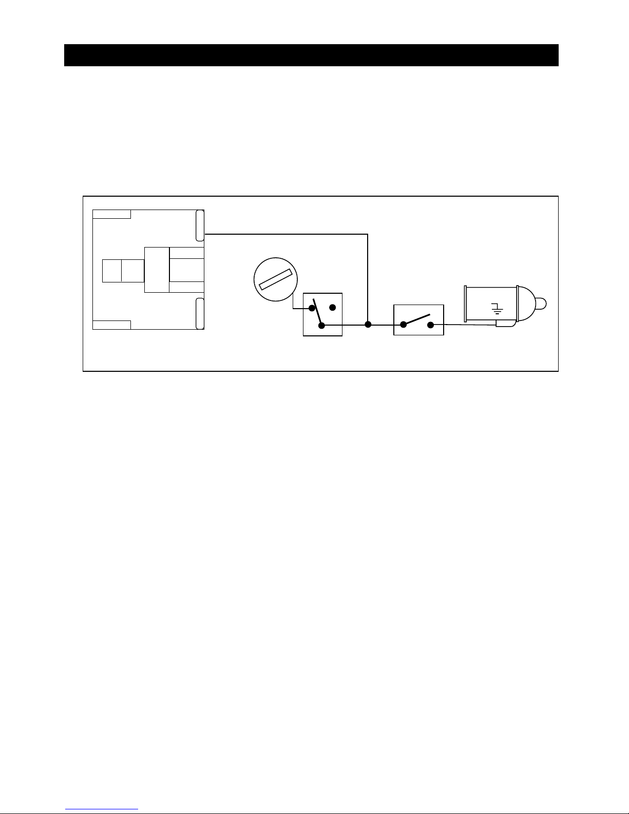
Violet Wire: (Starter Output)
Careful consideration for the connection of this wire must be made to prevent the vehicle from starting while
in gear. Understanding the difference between a mechanical and an electrical Neutral Start Switch will allow
you to properly identify the circuit and select the correct installation method. In addition you will realize why
the connection of the safety wire is required for all mechanical switch configurations.
Failure to make this connection properly can result in personal injury and property damage.
In all installations it is the responsibility of the installing technician to test the remote start unit and assure
that the vehicle can not start via RF control in any gear selection other than park or neutral.
Page 4
Wiring
4
White 6-Pin Heavy Gauge Wiring Connector (continued)
Violet Wire: (continued)
In both mechanical and electrical neutral start switch configurations, the connection of the “Violet” wire will
be made to the low current start solenoid wire of the ignition switch harness. This wire must have +12 Volts
when the ignition switch is turned to the “START” (crank) position only. This wire have 0 volts in all other
ignition switch positions.
Note: If a starter disable relay is installed, the connection of the violet wire must be at the starter side of the
relay, not the ignition switch side.
Failure to connect this wire to the ignition switch side of the neutral safety switch can result in personal injury
and property damage (See Neutral Start Safety Test for further details).
Red Wires (2): (+12 V Power Input)
Remove the two 20A fuses prior to connecting these wires and do not replace them until the harness has
been plugged into the control module. These wires are the source of current for all the circuits the relay
harness will energize. They must be connected to a high current source. It is recommended that these wires
be connected to the 12V battery terminal.
Yellow Wire: (Ignition 1 Output)
Connect the “Yellow” wire to the ignition 1 wire from the ignition switch. The ignition wire should receive +12
volts” when the ignition key is in the “ON” or “RUN” and “START” or “CRANK” position. When the ignition is
turned “OFF”, the ignition wire should receive “0” voltage. The yellow wire must be connected.
Pink Wire: (Ignition 2 Output)
Some vehicles have 2 ignition wires that must be powered. Connect the “Pink” wire to the Ignition 2 wire from
the ignition switch. No connection is required on vehicles without a second ignition.
Brown Wire: (Accessory Output, Heater/ACC Output)
Connect the “Brown” wire to the accessory wire that powers the climate control system. An accessory wire
will show +12 Volts when the ignition switch is turned to the “ACCESSORY” or “ON” and “RUN” positions, it
will show 0 Volts when the key is turned to the “OFF” and “START” or “CRANK” position. There will often be
more than one accessory wire in the ignition harness. The correct accessory wire will power the vehicle’s
climate control system. Some vehicles may have separate wires for the blower motor and the air conditioning
compressor. In such cases, it will be necessary to add a relay to power the second accessory wire.
"ACC" "START"
"OFF" "ON"
Starter
Start Cut Relay
(When Used)
Violet Wire
Closed in Park
or Neutral Only
Neutral Safety
Switch
Page 5
5
Wiring
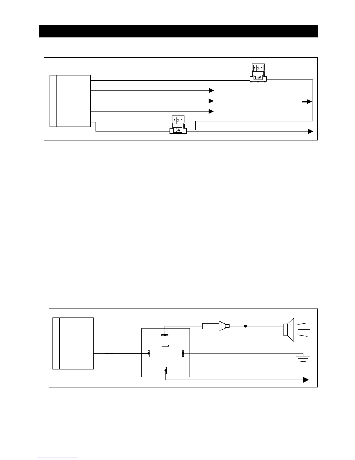
Red Wire with White Stripe: (Parking Light Relay Input)
The “Red/White” wire has already been assembled to work with a +12 Volt switched parking light system (most
vehicles). For vehicles with ground switched parking light activation cut this wire and connect it to ground.
White Wire: (Parking Light Relay Output, +12V 10A Output + or - Selectable)
Connect the “White” wire to the parking light wire coming from the headlight switch. Do not connect the
“White” wire to the dashboard lighting dimmer switch (damage to the dimmer will result). The limitation of
the “White” wire is 10 Amp max. Do not exceed this limit or damage to the alarm and parking relay will result.
Black Wire: (System Ground)
This is main ground connection of the alarm module. Make this connection to a solid section of the vehicle
frame. Do not connect this wire to any existing ground wires supplied by the factory wire loom, make the
connection to the vehicle’s frame directly.
Brown Wire: (Programmable Siren Drive Output - Factory Default Setting)
This is the positive (+) output connection for the siren, current capacity is 2 Amps. Make connection to the (+)
red wire from the siren. Make the (-) black wire coming from the siren to a good chassis ground.
(+) Low Current Horn Output (See Alarm Feature Programming Part 2 to Horn Output - Optional Setting)
This wire is provided to use the existing vehicle’s horn as the alarm system’s primary audible warning device. It’s
a transistorized low current output, and should only be connected to the low current positive (+) output from the
vehicle’s horn switch. Vehicle horn systems that require a (-) trigger will require an additional relay as shown.
Red Wire: (System Power +12V Constant)
The “Red” wire supplies power to the system. Connect this wire to a constant +12V source.
87
87a
86
85
30
Brown Wire
To Ground
To Horn
+12V or Ground Depending
on System Requirements
Fuse
White 5-Pin Connector
Red/White Wire Parking Light Relay Power Input
White Wire Parking Light Relay Output
Black Wire Ground to Vehicle Frame
Brown Wire Positive Output to Siren
Red Wire
Red Wire +12V Input
Cut this Wire and
Ground It for Ground
Trigger Parking Lights
(Ground Switching
Parking Light System Only)
Page 6

6
Wiring
White 2-Pin Connector
LED Status Indicator:
The LED indicator status should be mounted in a highly visible area such as top of the dashboard, on top of
the shifter console or on dashboard face. Leave at least 6mm space behind the mounting location for LED
housing. Once a suitable location is chosen, drill a 1/4" hole. Run the LED wires though the hole then press
the 2-Pin LED housing into the place. Route the LED wires to the control module.
Blue 2-Pin Connector
Valet Switch
Select a mounting location for the switch that is easily accessible to the driver of the vehicle. The switch does
not have to be concealed, however, concealing the switch is always recommended, as this provides an even
higher level of security to the vehicle. Mount the valet switch in a hidden but accessible location. Route the
valet switch wires to the control module.
White 6-Pin Mini Connector
Yellow Wire (-) 200mA Ignition 3 Control Output
Black/Green Wire (-) 200mA Time Control Channel 4 Output
Gray Wire (-) 200mA Channel 3 (Trunk) Output
Pink Wire (-) 200mA Programmable Output,
• Horn Output (Factory Default Setting) or
• Factory Security Rearm Signal Output or
• Start Status (Shock Sensor Bypass Control) Output
Orange Wire (-) 500mA Grounded Output when Armed
Tan and White 4-Pin Data Adapter Cable
Connects the alarm module with direct plug-in to "D2D" Data Adapters.
Page 7

Wiring
7
White 6-Pin Mini Connector (continued)
White Wire
Dome Light Control Output: (Factory Default Setting)
This wire becomes grounded when the dome light control circuit of the alarm is active. The current capacity
of this wire is 200mA. This wire can control the operation of the interior lights. An optional relay can be
used as shown.
A. Upon disarming, the interior lights will remain on for 30 seconds.
B. If the vehicle is violated, the interior light will flash for the same duration as the siren.
Common Door Pin Trigger
White Wire
Ground Wire or Connect to + 12V
Depending on Circuit Requirements
+12V
Dome
Light
87
87A
85
86
30
2 Step Door Unlock Output: (See Alarm Feature Programming Part 3)
The 2 step unlock feature will work for the most fully electronic door lock circuit. The vehicle must have an
electronic door lock switch (not the lock knob or key switch), which locks and unlocks all of the vehicle’s
doors. When wired for this feature, pressing the disarm (or unlock) button one time will disarm the alarm
and unlock the driver’s door only. Press disarm (or unlock) button two times within 3 seconds, the alarm
will disarm and all doors will unlock. (See Page 13 for Wiring)
Factory Security Disarm Signal Output: (See Alarm Feature Programming Part 3)
This wire is designed to disarm a factory installed security system. This wire sends a negative (-) 1 second
pulse upon a remote start and remote door unlocking. Some factory systems must be disarmed to allow
remote starting. In most cases, this wire may be connected directly to the factory alarm disarm wire. The
correct wire will show negative ground when the key is used to unlock the doors or trunk. This wire is
usually found in the kick panel area in the wiring harness coming into the car body from the door.
Ground Output During Start (Crank): (See Alarm Feature Programming Part 3)
This wire will provide a 200mA ground output while the starter output of the remote start unit is active. This
output can be used to activate the Crank Low/Bulb test wire found in some GM vehicles. this wire is also
referred to as the ECM wake up wire in some vehicles.
Page 8

8
Wiring
Ignition: 3-Wires from
Ignition Key switch
Constant +12V:
Fused 25A Capable
Yellow Wire
87
87A
85
86
30
White 6-Pin Mini Connector (continued)
Yellow Wire: (-) 200mA Ignition 3 Output
This wire provides a 200mA (-) ground output that becomes active in 4 seconds before the remote start unit
initializes and remains grounded while running. It may also be used for an immobilizer bypass module.
Ignition 3 Output:
Some newer vehicles use a third ignition wire which is required to start and keep the vehicle’s engine
running. If this is the case, wire an IGN 3 Relay (not supplied) as shown:
DO NOT CONNECT ANY VEHICLE CIRCUITS TOGETHER, THEY ARE ISOLATED FOR A REASON.
Transponder Interfacing Using ALA984 Relay (may also use optional RS-TIM bypass module):
If the vehicle has transponder system installed, you will need to bypass the system while the vehicle is
operating under the control of the Remote Start Unit. To do this, follow these steps:
1. You will need a transponder key that's already programmed to the vehicle.
2. Remove the trim around the ignition switch.
3. Wrap a thin (30awg) wire tightly around ignition switch 6 to 8 times and secure it.
4. About 6" down line make another loop of approximately 2" diameter.
5. Place the key inside this loop and secure it to the loop.
6. Connect one end of the 30 awg wire to pin (87) of the relay module.
7. Connect the other end of the loop wire to pin (30) of relay module.
8. Connect the pin (86) of the relay module to the ignition wire from the ignition switch.
9. Connect the pin (85) of the relay module to the yellow wire of 6-pin connector.
Transponder Key
87
87A
85
86
30
Ignition
Switch
+12 Volt Ignition
Yellow Wire
Page 9

Wiring
White 6-Pin Mini Connector
(continued)
Yellow Wire: (continued)
GM VATS Key Override Using ALA984 Relay
(may also use optional RS-PLM bypass module)
87
87A
85
86
30
To Ignition
Passkey Wire
Computer Side
Orange or Black Plastic Tube
at Steering Column
Matching Resistor
Cut
Passkey Wire
Key Side
Yellow Wire
Matching
Resistor
Yellow
Trucks: Orange/Black or Cars: Black
87
87A
85
86
30
To Vehicle's Ignition Wire
Trucks: Red/White or Cars: White
Yellow Wire
Passkey ll Key Override Using ALA984 Relay
Black/Green Wire: (-) 200mA Timer Control Channel 4 Output/Key Sensor Output
(See Alarm Feature Programming Part 3) (Factory default setting on momentary ground) This wire is a built-in
user programmable timer that provides a ground output. You may program the built-in timer to send a
ground signal for any time interval between 1 second and 2 minutes. For instance, this timer output may be
used to turn on the headlights with the remote control. Also, on certain Mercedes Benz, BMW, Jaguar and
Volkswagens you can use this unique timed output to allow remote closure of all power windows and sunroof
without the need for an external module.
Gray Wire: Channel 3 (Trunk Release) Output
This will become a 1 second pulse ground by activating Channel 3 on transmitter for two seconds, the current
capacity of this wire is 200mA. This feature allows you to remote control trunk release or other electric device.
Input to Relay (+ or -)
87
87A
85
86
30
To Constant +12 Volts
Gray Wire
Output to Power Trunk Switch
9
Page 10
Wiring
10
White 6-Pin Mini Connector
(continued)
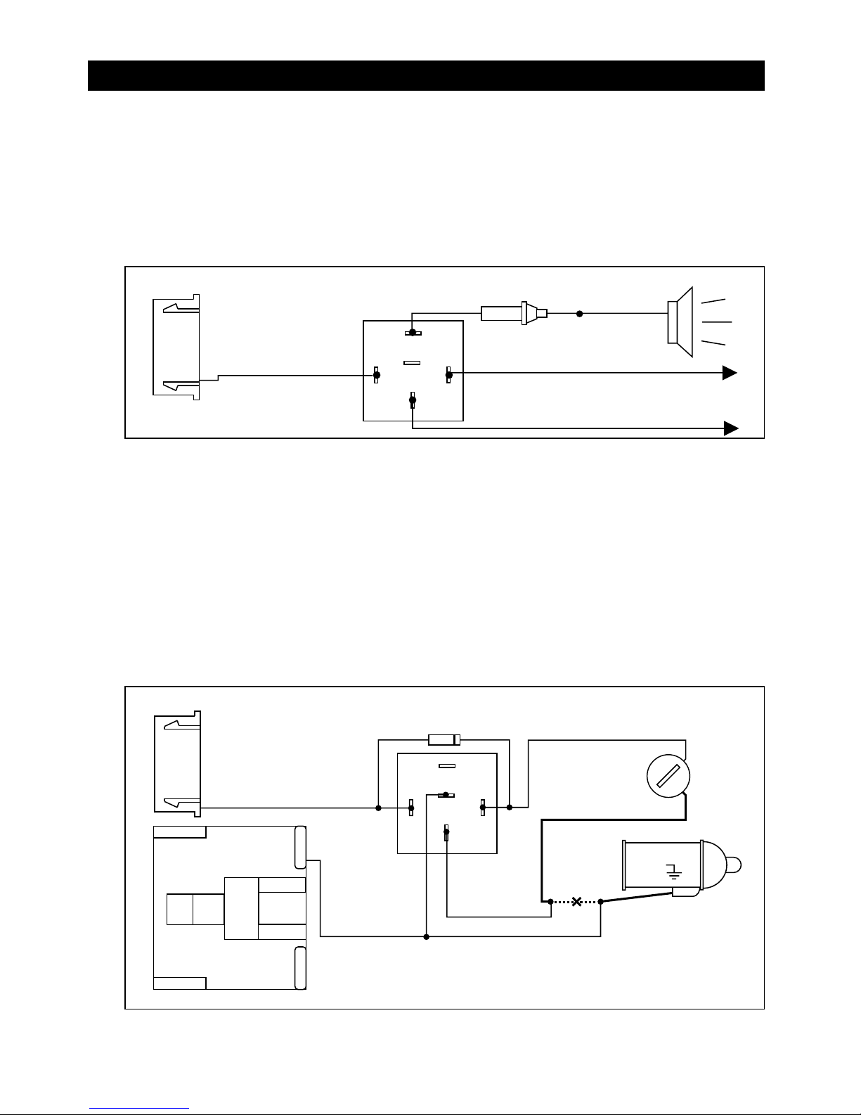
Pink Wire: (-) 200mA Programmable Output
(See Feature Programming Part 3)
Horn Output: (Factory Default Setting)
This wire can be used to activate the existing vehicle’s horn as the alarm system’s optional warning audible
device. It’s a transistorized low current output, and should only be connected to the low current ground
output from the vehicle’s horn switch. When the system is triggered, the horn will sound (depending on the
vehicle’s requirement an additional relay may be needed as shown).
87
87A
85
86
30
"START"
"OFF"
"ON"
Starter
IN4003 Diode
Cut
Orange Wire
"ACC"
Violet Wire
+12V
To Horn
+12V or Ground Depending
on System Requirements
Fuse
Pink Wire
87
87A
85
86
30
Factory Security Rearm Signal Output: (See Alarm Feature Programming Part 3)
This wire can be used to rearm a factory installed security system. This wire will supply a pulse whenever
the remote start times out or is shut down using the transmitter and remote door locking.
Start Status (Shock Sensor Bypass Control) Output: (See Alarm Feature Programming Part 3)
This wire is designed to bypass the shock sensor module. This wire will supply an output at all times the
remote start is operating plus an additional 3 seconds after the remote start unit turns off.
Orange Wire : (-) 500mA Grounded Output when Armed)
This wire will become grounded when the alarm is armed. The current capacity of this wire is 500mA. This
output can control a starter disable relay, when the system is triggered. The vehicle is prevented from any
unauthorized starting, and also becomes activated when the engine is remote started.
Page 11

Wiring
3 Wire Positive Trigger Door Lock System
(+) Lock Out
+12 Volts Input
(+) Unlock Out
To Door Lock
Control Relays
Blue Wire: Connect to Lock
Green Wire: Connect to Unlock
Lock Control
Switch
11
3 Wire Ground Trigger Door Lock System
(-) Lock Out
Ground Input
(
-
) Unlock Out
To Door Lock
Control Relays
Lock Control
Switch
Blue Wire: Connect to Unlock
Green Wire: Connect to Lock
Black 3-Pin Mini Connector
5 Wire Ground at Rest Door Locking Systems
87
87A
85
86
30
87
87A
85
86
30
To +12 Volts
(Battery +)
To Power
Lock Switch
To Power
Lock Motors
White Wire: Lock
Brown Wire: Unlock
Green Wire: Lock
Blue Wire: Unlock
Violet Wire
ALA-DL1
Relay Pack
Red Wire: Lock
Green Wire
Blue Wire
Note: Orange wire from ALA-DL1
must be connected to +12V
Black Wire: Unlock
Newly Installed Power Door Lock Motors
87
87A
85
86
30
87
87A
85
86
30
To +12 Volts
(Battery +)
To Ground
To Newly
Installed Power
Door Lock Motors
White Wire
Brown Wire
Green Wire: Lock
Blue Wire: Unlock
Violet Wire
ALA-DL1
Relay Pack
Red Wire: Lock
Green Wire
Blue Wire
Note: Orange wire from ALA-DL1
must be connected to +12V
Black Wire: Unlock
Page 12
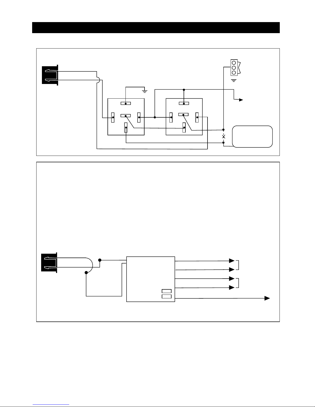
12
Wiring
Black 3-Pin Mini Connector
(continued)
One Wire Multiplexing Door Locking Systems
Some vehicles (Chrysler, Mazda and Ford Probe and others) use one wire to lock and unlock the doors.
Example: When the door lock controller sees a signal thru a resistor it will unlock. If a signal is received
without a resistor the doors will lock. Some use 2 resistors. One for lock and one for unlock. We have
developed patented plug-in fuse resistors for this application. Simply remove the fuse from our door lock
module and replace with correct resistor value fuses that matches the vehicles door lock switch.
Wiring:
1. Connect both the green (lock) and the blue (unlock) wires to the vehicles one wire lock/unlock wire.
2. Connect our violet polarity input wire to +12V or to ground. To match vehicles door lock polarity.
3. The white and the brown wires will not be used.
White Wire Lock
To Power
Lock Switch
To Power
Lock Motors
Brown Wire Unlock
Green Wire Lock
Blue Wire Unlock
Violet Wire To +12 Volts Constant
Lock Fuse 1
Unlock Fuse 2
ALA-DL1
Red Wire
Black Wire
Green Wire
Blue Wire
Note: Orange wire from ALA-DL1 must be connected to +12V.
Mercedes Door Lock Activation
Door Lock
Switch
Unlock
Lock
B+
87
87A
85
86
30
87
87A
85
86
+
++
To +12 Volts
(Battery +)
Door Lock
Compressor
Cut
Green Wire
Unlock
Lock
Green Wire
Blue Wire
Page 13
13
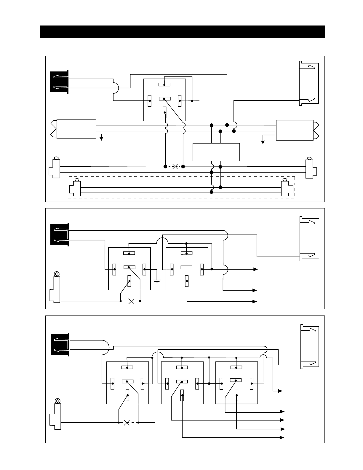
Wiring
Black 3-Pin Mini Connector
(continued)
Unlock Driver's Door First for 3-Wire Negative Door Lock Systems
87
87A
85
86
30
Unlock Wire
Passenger's Door
Lock
Unlock
To +12V or Ground
To +12V or Ground
Driver's Door
Rear Doors
Passenger's
Door Switch
Door Lock Relay
Control Module
Lock
Unlock
+12V
Driver's Door
Switch
Cut
Blue Wire
Green Wire
White Wire
6-Pin White
Mini Connector
Unlock Driver's Door First Wiring for 3-Wire Positive Door Lock System
87
87A
85
86
30
To +12 Volts
(Battery +)
To Power Door
Lock Switch
Lock/Unlock Wires
Lock
Unlock
87
87A
85
86
30
+ Unlock
Cut
Driver's
Door Motor
Green Wire
Blue Wire
6-Pin White
Mini Connector
White Wire
White
Wire
Unlock Driver's Door First Wiring for 5-Wire Ground at Rest Door Locking Systems
87
87A
85
86
30
87
87A
85
86
30
To +12 Volts
(Battery +)
To Power
Lock Switch
To Power
Lock Motors
Lock
Lock
Unlock
Unlock
87
87A
85
86
30
+ Unlock
Cut
Driver's
Door
Motor
Green Wire
Blue Wire
6-Pin White
Mini Connector
Page 14
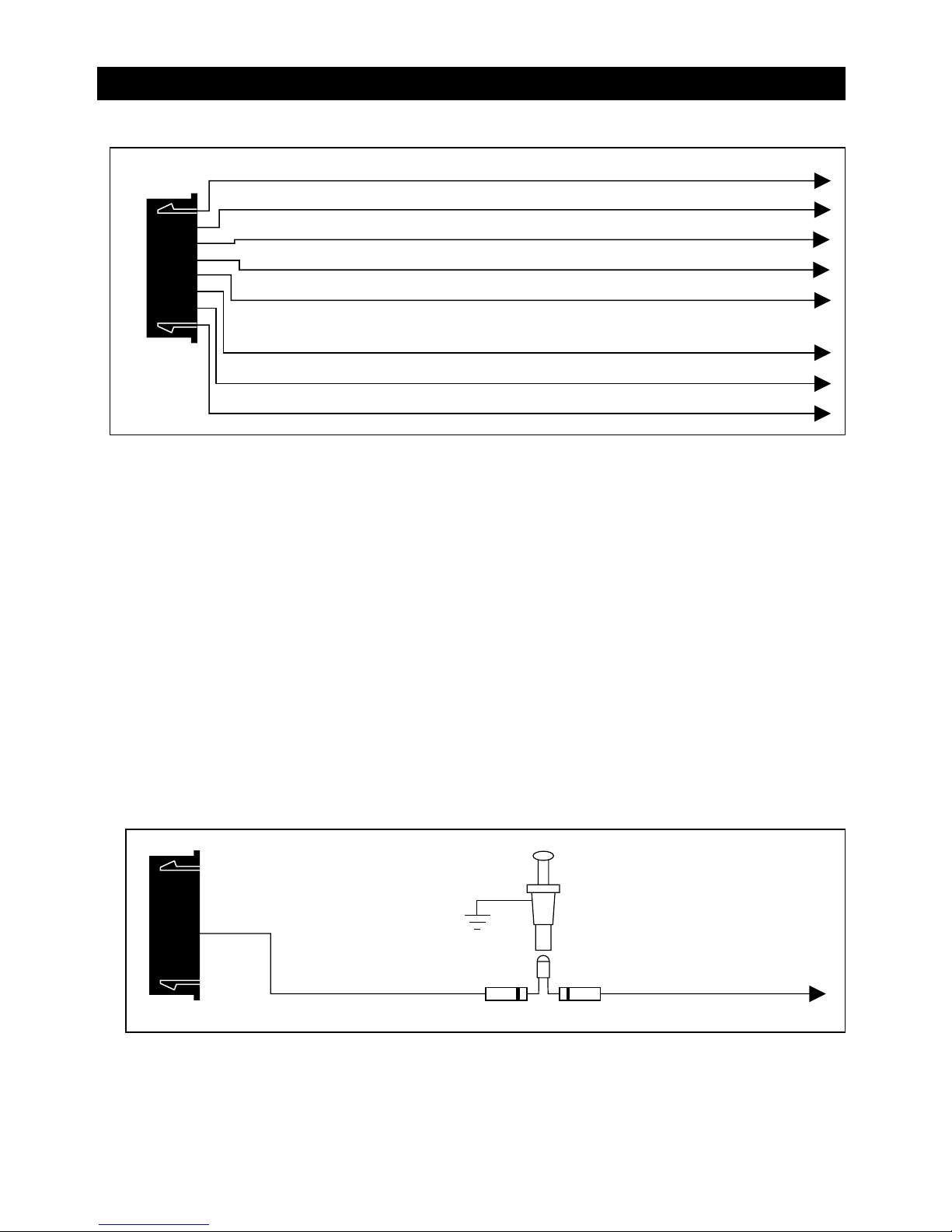
Wiring
14
Black 8-Pin Mini Connector
Blue Wire Zone 2 Instant Trigger Ground Input
Green Wire Zone 3 Negative Door Pin Trigger Input
Violet Wire Zone 3 Positive Door Pin Trigger
White/Blue Wire (-) Instant Start and Turn Off Input
White/Black Wire (-) Negative Safety Shut Down Input for Hood Pin Switch
Black/White Wire (-) Neutral Safety Switch Input and
(-) Remote Start Toggle Switch Input
White/Violet Wire (+) Positive Safety Shut Down Input for Brake Switch
White/Red Wire Tach Signal Input
Blue Wire: (-) Ground Instant Trigger Input (Zone 2)
This wire is the ground trigger input wire for hood/trunk pin switches.
Green Wire: (-) Negative Door Trigger Input (Zone 3)
This wire is the ground trigger input wire for negative door pin switch.
Violet Wire: Positive Door Switch Sensing Input (Zone 3)
This wire is the positive trigger input wire for positive door pin switch.
White/Blue Wire: (-) Instant Start and Turn Off Input
This wire activates and turns off the remote starter each time it sees a momentary ground signal. Normally used for
testing during installation or when activating the module from an after market system.
White/Black Wire: (Negative Safety Shut Down Input)
The White/Black wire provides an instant shutdown for the remote start, whenever it is grounded. Connect the wire
to the hood pin switch previously installed. this wire must be routed through a grommet in the firewall and
connected to the hood pin switch. If the pin switch is to be used with an alarm system, connect this wire with
diode. Diodes are required when the hood pin is used as a triggering device. Wire as shown.
Hood Pin Switch (Provided)
White/Black Wire
Diode Diode
To Alarm Instant
Trigger Blue Wire
Page 15
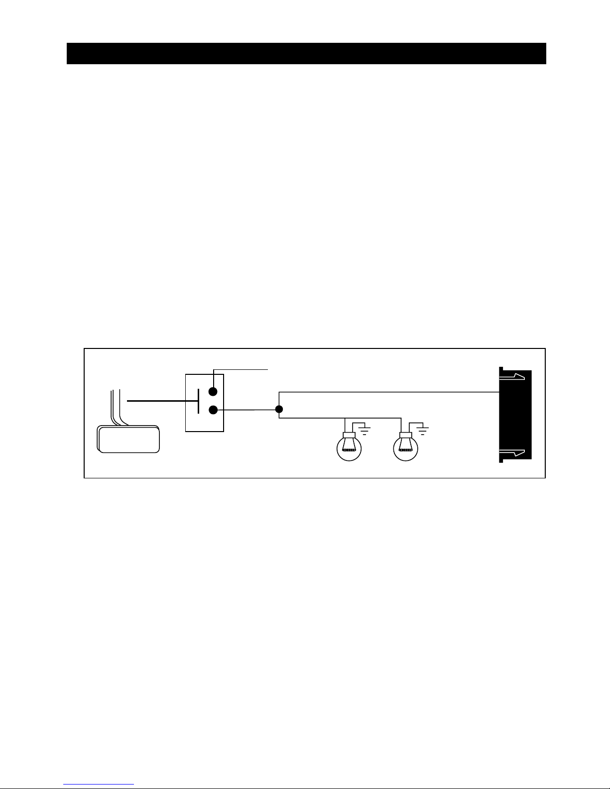
15
Black 8-Pin Mini Connector
(continued)
Black/White Wire: (-) Remote Start Enable Toggle Switch Input, (-) Neutral Safety Switch Input
When the Black/white wire is grounded, the remote start unit is operable. When this wire is open from ground, the
remote start is disabled.
1. An optional “Remote Start Toggle Switch” can be added on to temporarily disable the Remote Start Device, it
can prevent the vehicle from being remote started accidentally. This feature is useful if the vehicle is being
serviced or stored in an enclosed area. To disable the remote start, move the optional remote start enable
toggle switch to the OFF position. To enable the remote start, move the optional remote start enable toggle
switch to the ON position.
2. If needed, this wire can connect to the Park/Neutral switch in the vehicle (See testing in your installation guide).
Important Note: Directly connect the Black/White wire to the “Ground” when this wire is not used for it’s
intended safety purpose or remote start will not operate.
Wiring
Brake Light Bulbs
+12 Volts
Switch Closes when
Brake is Depressed
White/Violet Wire
Brake Pedal
To Lights
White/Red Wire: (-) Tachometer Signal Connection
This input provides the remote start system with information about the engine’s revolutions per minute
(RPM). It can be connected to the negative side of the coil in vehicle with conventional coils. In multi-coil and
high energy ignition system locating a proper signal may be more difficult. Once connected, you must
program the Start Feature Stage 2 to “Tachometer Checking Type" and teach the system the RPM signal (see
Start Feature Stage 2 Programming).
In multi-coil ignition system, the system can have individual coil wires. Individual coil wires in a multi-coil
ignition system will register lower amounts of AC voltage. A common location for a tachometer wire is the
ignition coil itself, the back of the gauges, engine computers and automatic transmission computers.
Important! Do not test tachometer wires with a test light or logic probe. Electronic components of
the ignition system will be damaged.
How to find a tachometer wire with a multi-meter:
1. Set the ACV or AC voltage *(12V or 20V is OK).
2. Attach the (-) probe of the meter to chassis ground.
3. Start and run the vehicle.
4. Probe the wire you suspect of being the tachometer wire with the red probe of the meter.
5. If this is the correct wire the meter will read between 1V and 6V
at idle, and will increase as engine RPM
increases.
Note: No connection of this wire is required if you use the voltage or timer checking type mode.
White/Violet Wire: Positive Safety Shut Down Input
This wire provides an instant shutdown for the remote start, whenever it gets +12 volts. If the brake lights switch
in the vehicle switches +12 Volts to the brake light circuit, connect this wire to the output side of the brake switch.
This will allow the remote start to shut down if an attempt is made to operate the vehicle without the key while
running under the control of the remote start. In most vehicles, in order to shift gear, the brake pedal must be
depressed. The brake input will in turn cause the remote start unit to shut off.
Page 16
16
Wiring
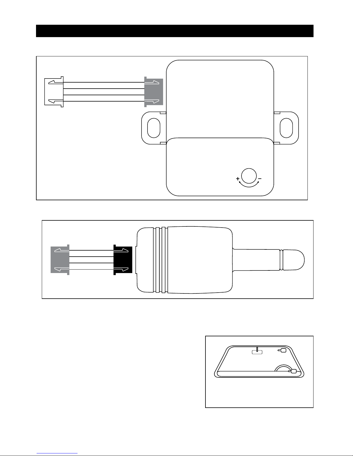
Blue 4-Pin to Black 4-Pin Harness
Two-Way Transceiver/Antenna Module:
The two-way transceiver/antenna mounts on the windshield (inside). We suggest you mount it on the lower
left or upper left hand side of windshield (driver side). Warning! Do not mount in such a manner that it
obstructs the drivers view.
• Remove the protective tape backing.
• Carefully align the two-way transceiver/antenna and apply to
windshield.
• Route the black connector wire behind the trim and connect
to the two-way transceiver/antenna.
• Connect the other end to the control module.
• Special considerations must be made for windshield glass as
some newer vehicles utilize a metallic shielded window glass
that will inhibit or restrict RF reception. In these vehicles,
route the two way transceiver/antenna module away from
metallic shielded window glass as far away as possible.
White 4-Pin to Red 4-Pin Harness
Mount the antenna horizontally for
best reception.
2-Stage Sensor:
Allows easy connection with quick
disconnect ability for other optional
devices.
1. Red: +12 Volt Constant Input
2. Black: Main Sensor Ground
3. Blue: Instant Trigger (-) Input
4. Green: Warn Away (-) Input
Page 17
17
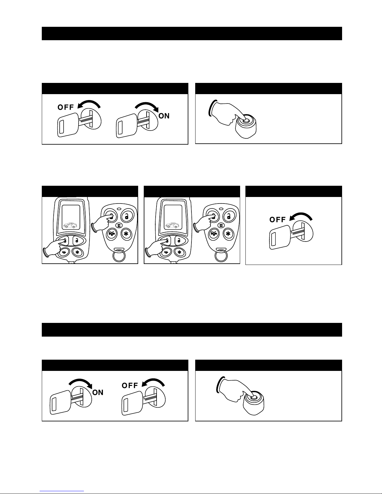
Alarm Feature Programming (Part 1)
Examine the 3 different feature charts enclosed and decide which feature will get changed. Circling the feature to
be changed will make the programming process much easier to perform.
Turn the ignition switch from the OFF position to the
ON position 3 times leaving it in the OFF position the
third time.
Before 15 seconds has passed, push and release the
valet switch 1 time then push the valet switch a second
time and hold it down until 1 short and 1 long chirp or
beep is heard, then release it. You are now in Alarm
Feature Programming Part 1 programming mode
Step 1 Step 2
3X
1X + 1X (Hold)
Turn the ignition switch from the OFF position to the
ON position 3 times leaving it in the ON position the
third time.
Before 15 seconds has passed, push and release the valet
switch 2 times then push the valet switch a third time and
hold it down until a long chirp or beep is heard, then
release it. You are now in transmitter programming mode.
Step 1 Step 2
3X
2X + 1X (Hold)
Step 3
Press the “Lock” button on the first
transmitter until you hear a
confirmation chirp/beep. The
transmitter is now coded into the
system.
Repeat for each additional
transmitter.
Step 5
When finished, either turn off the
ignition key or wait for 15 seconds to
get out of transmitter programming
mode. You will hear 3 long
chirps/beeps to indicate you are out of
the transmitter programming mode.
Programming the Transmitter
Programming the Remote Transmitter
(Includes the Standard Type and LCD Transmitter Type)
Note: This mode will only retain the last 4 remote transmitters programmed. If the transmitter memory is
exceeded, the security system will start deleting transmitters from memory in chronological order.
Step 4
Page 18
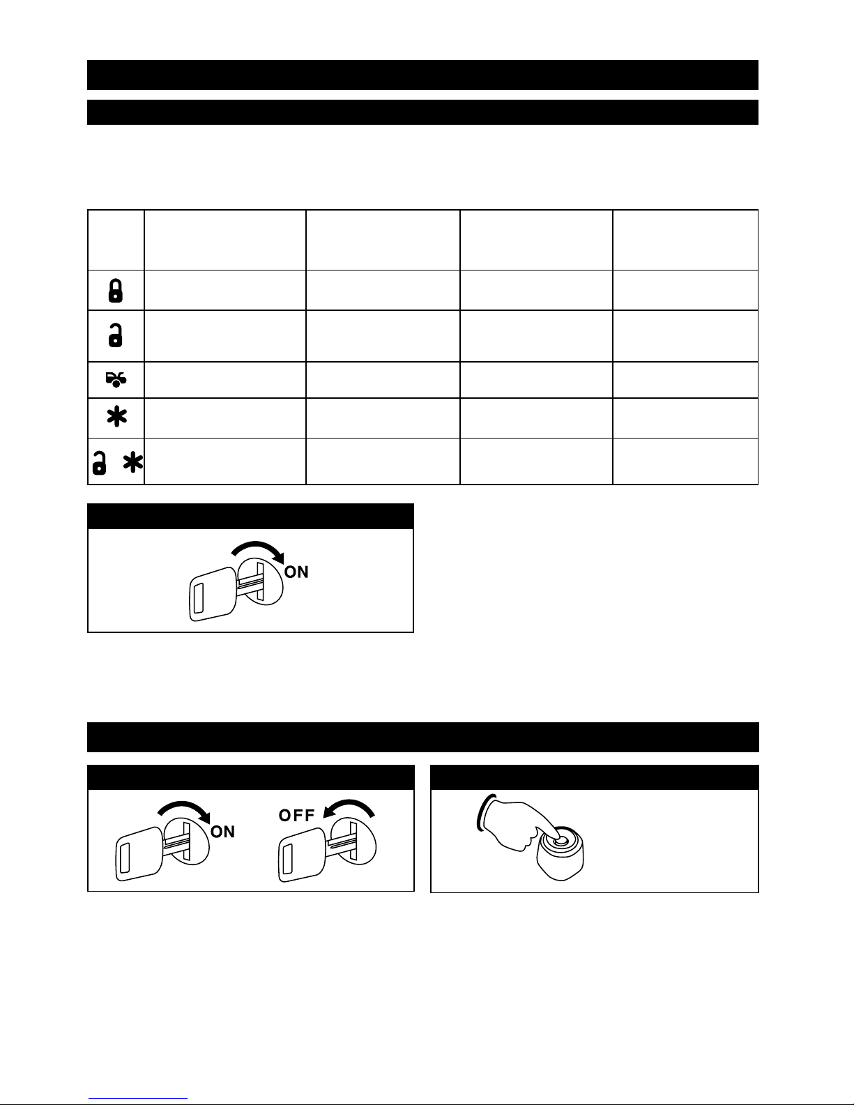
18
Turn On the Ignition
3 long chirps and 3 flashes of the parking lights will
confirm exit of the programming mode.
Note: Waiting 15 seconds after the last command will
also cause the system to automatically exit the
programming mode.
One Chirp Two Chirps Three Chirps Four Chirps
Button LED One Pulse LED Two Pulses LED Three Pulses LED Four Pulses
(Factory Default Setting)
Step 4
Step 3
Remote Feature Programming
Use the transmitter buttons as illustrated to adjust the features required. Keep repressing the transmitter button
that relates to the feature you want to adjust until the correct amount of chirps/beeps is heard. Move on to the
next feature.
All Chirps Siren Only Horn Only All Chirps Off
Passive Arming without
Passive Door Locking
Passive Arming with
Passive Door Locking
Active Arming
Automatic Rearm Off Automatic Rearm On
Instant Door Ajar Warning
Door Ajar Error Chirp with
45 Second Check Delay
Inactive Car-Jack Mode
Active Car-Jack Mode
+
Passive Car
Jack Mode
Alarm Feature Programming (Part 1)
Alarm Feature Programming (Part 2)
Turn the ignition switch from the OFF position to the
ON position 3 times leaving it in the OFF position the
third time.
3X 3X + 1X (Hold)
Before 15 seconds has passed, push and release the
valet switch 3 times then push the valet switch a fourth
time and hold it down until 2 short chirps/beeps + 1
long chirp/beep is heard then release it. You are now in
Part 2 programming mode.
Step 1 Step 2
Page 19
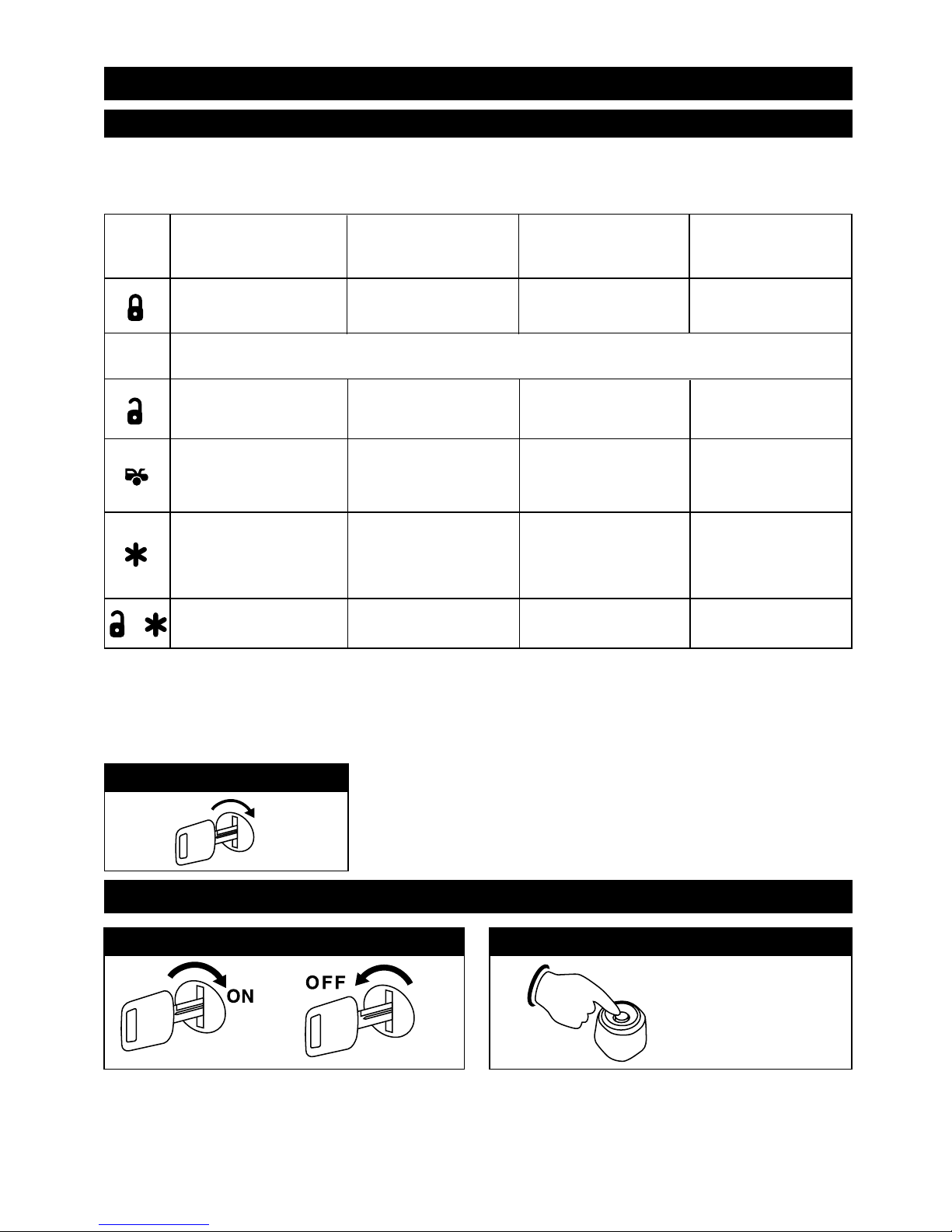
Alarm Feature Programming (Part 3)
Turn the ignition switch from the OFF position to the
ON position 3 times leaving it in the OFF position the
third time.
Before 15 seconds has passed, push and release the
valet switch 5 times then push the valet switch a sixth
time and hold it down until 3 short chirp/beeps + 1
long chirp/beep is heard then release it. You are now in
Part 3 programming mode.
Step 1 Step 2
3X
5X + 1X (Hold)
19
Step 3
Remote Feature Programming
Use the transmitter buttons as illustrated to adjust the features required. Keep repressing the transmitter button that
relates to the feature you want to adjust until the correct amount of chirps/beeps is heard. Move on to the next feature.
One Chirp / Two Chirps / Three Chirps / Four Chirps /
Button LED One Pulse LED Two Pulse LED Three Pulse LED Four Pulse
(Factory Default Setting)
Parking Light “On” for
30 Seconds Upon an
Unlock Signal
0.8 Second
Door Lock Pulses
0.6 Second
Door Lock Pulses
3.5 Second
Door Lock Pulse
Ignition Controlled
Door Lock Only
Ignition Controlled
Door Unlock Only
Ignition Controlled
Door Lock and Unlock
Without Ignition Controlled
Door Lock and Unlock
Doors Lock Before Start
Doors Lock After
Shut-Down
Pathway Illumination
Feature “Off”
Doors Lock Before Start
and Doors Lock After
Shut-Down
Door Lock with
“Comfort Feature”
See Note Below
Parking Light “On” for 30
Seconds Upon an Unlock
Signal and 10 Second Upon
a Lock Signal
Disables the Out-of-
Range Check
+
Enables the Out-of-
Range Check
Alarm Feature Programming (Part 2)
ON
Turn On the Ignition
3 long chirps and 3 flashes of the
parking lights will confirm exit of
the programming mode.
Note: Waiting 15 seconds after the
last command will also cause the
system to automatically exit the
programming mode.
Step 4
Without this Feature
Comfort Feature:
Some vehicles have a special “Comfort Feature”. When you lock the door with the key, you have to hold the key in the
lock position for about 5 to 7 seconds for the windows will close automatically. If you wish the vehicle’s Comfort
Feature to be activated when you remotely lock the doors, program
Door Lock with Comfort Feature “ON”
.
5 Chirps = 0.8 Second Double Pulse Unlock
6 Chirps = 0.6 Second Double Pulse Unlock
Page 20
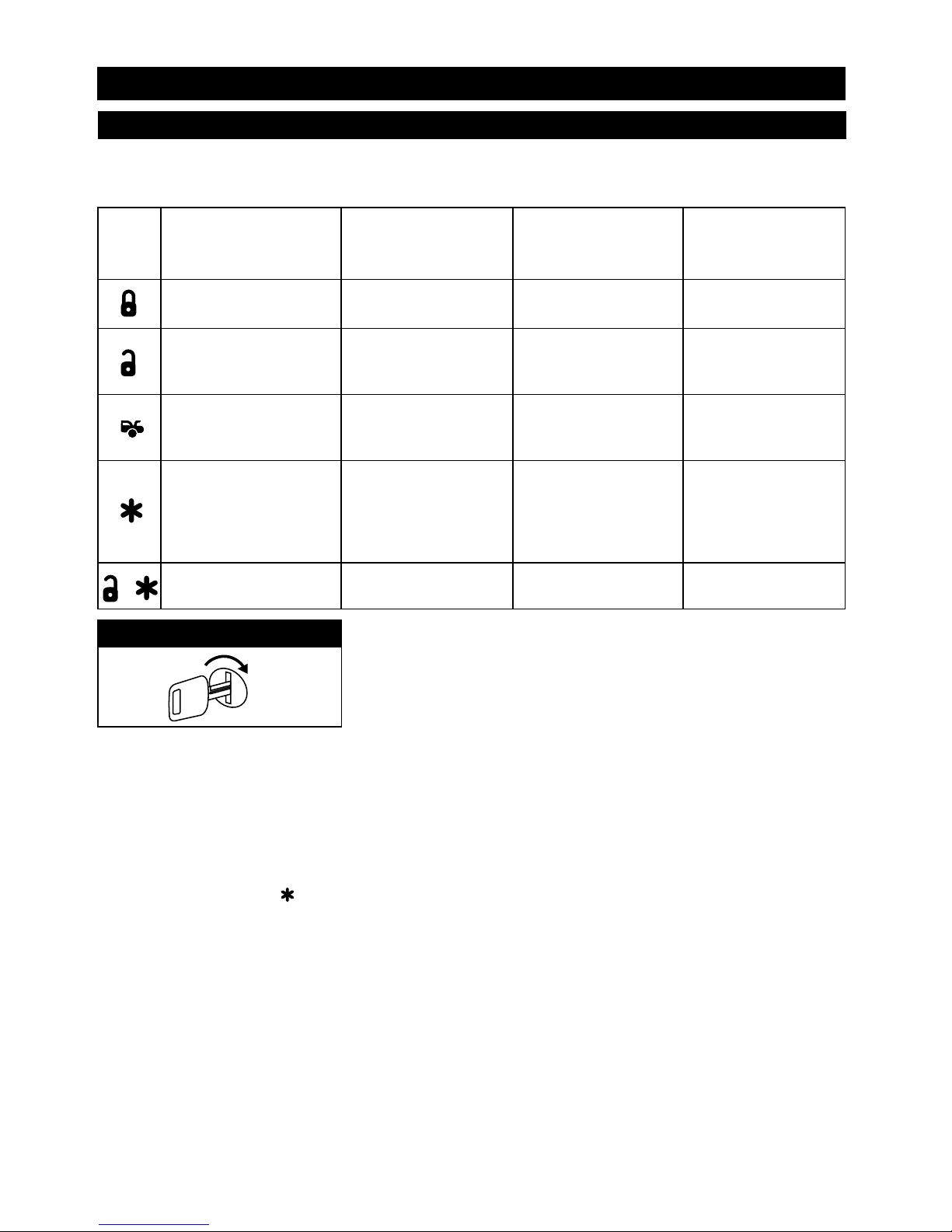
20
Step 3
Remote Feature Programming
Use the transmitter buttons as illustrated to adjust the features required. Keep repressing the transmitter button that
relates to the feature you want
to adjust until the correct amount of chirps/beeps is heard. Move on to the next
feature.
ON
Turn On the Ignition
3 long chirps and 3 flashes of the
parking lights will confirm exit of
the programming mode.
Note: Waiting 15 seconds after the
last command will also cause the
system to automatically exit the
programming mode.
Step 4
Alarm Feature Programming (Part 3)
One Chirp Two Chirps Three Chirps Four Chirps
Button LED One Pulse LED Two Pulse LED Three Pulse LED Four Pulse
(Factory Default Setting)
Black/Green Wire
Channel 4 Output =
Latched Output
Brown Wire = Constant
(+) Siren Output
Brown Wire = 5 Second
(+) Pulse Siren Output
White Wire = 2-Step Door
Unlock Output
White Wire =
Factory Security Disarm
Signal Output
White Wire =
Dome Light Output
White Wire =
Ground Output
During Start (Crank)
Pink Wire =
Horn Output
Pink Wire =
Factory Security Rearm
Signal Output
Black/Green Wire
Channel 4 Output =
Momentary Output
Pink Wire =
Start Status (Shock Sensor
Bypass Control) Output
Black/Green Wire
Channel 4 Output =
Timer programming (set
to any interval between
1 second and 2 minutes
Black/Green Wire
Channel 4 Output =
Latched Output and Reset
with Ignition “On”
+
White/Blue Wire =
1 Pulse Activate
White/Blue Wire =
2 Pulse Activate
White/Blue Wire =
3 Pulse Activate
Ground Output During Start (Crank) = This wire will provide a 200mA ground output while the starter output of
the remote start unit is active. This output can be used to activate the Crank Low/Bulb Test wire found in some
GM vehicles. This wire is also referred to as the ECM wake up wire in some vehicles.
Channel 4 Timer Control Output Programming.
1. Turn the ignition switch ON/OFF 3 times and keep it in the OFF position.
2. Push the valet switch 6 times, and hold it in on the 6th push until three chirps with a long chirp is heard then
release the switch. You are now in the Alarm feature ‘III’ programming mode.
3. Press and release the button 4 times. 4 LED flashes, 4 siren/horn chirps to indicate your are in features
“Channel 4 Timer Programming Mode”.
4. Press and hold the valet switch, the timer will then immediately start.
5. When the desired interval has passed, release the valet switch. One long chirp for confirmation (Set to any
interval between 1 second and 2 minutes).
Note 1: If your built-in timer controls window/sunroof closure in your car DO NOT change the timer setting! This
requires installer-only programming. Changing the value will adversely effect operation and may cause damage.
Note 2:
Momentary Output = The momentary output selection will output a negative signal from the Channel 4 output
immediately when the channel 4 button is pressed and will continue until the button is released.
Latched Output = The latched output selection will output a negative signal as soon as the Channel 4 button is
pressed and will continue until the button is pressed again.
Latched Output / Reset with Ignition = The latched / reset with ignition output selection operates just like the
latched output but will reset or stop when the ignition is turned on.
Brown Wire =
(+) Horn Output
Page 21
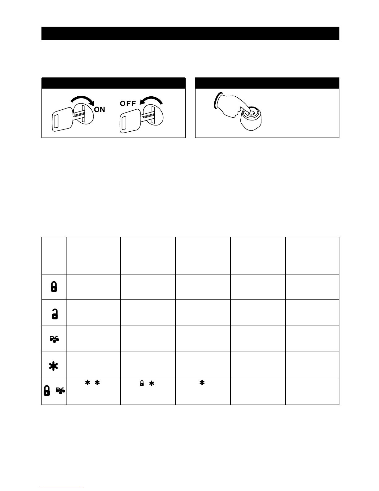
Remote Start Feature Programming
Use the transmitter buttons as illustrated to adjust the features required. Keep repressing the transmitter button
that relates to the feature you want to adjust until the correct amount of chirps/beeps is heard. Move on to the
next feature.
21
Turn the ignition switch from the OFF position to the
ON position 3 times leaving it in the OFF position the
third time.
Before 15 seconds has passed, push and release the
valet switch 7 times, then push the valet switch an
eighth time and hold it down until 4 short chirps/beeps
+ 1 long chirp/beep is heard then release it. You are
now in Stage 1 Remote Start Feature Programming
Mode.
3X
7X + 1X (Hold)
Remote Start Operation and Feature Programming (Stage 1)
Step 1 Step 2
Examine the 2 feature charts below and decide which features you wish to change.
Stage 1: Remote Start Operation Programming
One Chirp Two Chirps Three Chirps Four Chirps Five Chirps
Button LED One Pulse LED Two Pulse LED Three Pulse LED Four Pulse LED Five Pulse
(Factory Default
Setting)
Gasoline Engine
Diesel Engine and
10 Second
Warm-Up Timer
10 Minute
Run Time
Factory Alarm
Disarm with
Channel 3 On
Press - button
= Activates
Remote Start
Diesel Engine and
15 Second
Warm-Up Timer
Diesel Engine and
20 Second
Warm-Up Timer
20 Minute
Run Time
30 Minute
Run Time
5 Minute
Run Time
Without this
Feature
Constant Parking
Light Output
Flashing Parking
Light Output
+
Press + button
= Activates
Remote Start
Press button
= Activates
Remote Start
DBl Diesel
Page 22
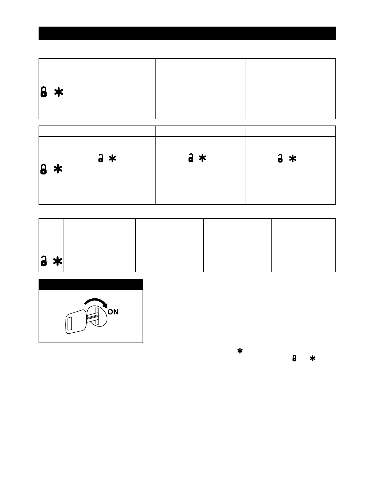
22
Remote Start Feature Programming (continued)
Remote Start Operation and Feature Programming (Stage 1)
Button
Four Chirps, LED Four Pulses Five Chirps, LED Five Pulses
Six Chirps, LED Six Pulses
Built-in Turbo Timer Control is
Active
Press the ( + ) buttons
before removing the ignition key
to activate the 1 minute Turbo
timer control. The alarm system
can be armed and the shock
sensor will be bypassed.
Built-in Turbo Timer Control is
Active
Press the ( + ) buttons
before removing the ignition key
to activate the 3 minute Turbo
timer control. The alarm system
can be armed and the shock
sensor will be bypassed.
Built-in Turbo Timer Control is
Active
Press the ( + ) buttons
before removing the ignition key
to activate the 5 minute Turbo
timer control. The alarm system
can be armed and the shock
sensor will be bypassed.
+
One Chirp Two Chirps Three Chirps Four Chirps
Button LED One Pulse LED Two Pulse LED Three Pulse LED Four Pulse
(Factory Default Setting)
3 Hour Time Start
+
2 Hour Time Start
Turn On the Ignition
3 long chirps and 3 flashes of the parking lights will confirm exit of the
programming mode.
Note: Waiting 15 seconds after the last command will also cause the
system to automatically exit the programming mode.
Step 4
Safe Start (Child Safety Mode) = Factory defaults setting to press the button twice to start the vehicle.
Programming this feature to eliminate an accidental remote start requiring the user to press the and buttons
at the same time to start the vehicle.
(Factory Default Setting)
Turbo Timer Control
Function is Off.
The alarm can not be armed
while the engine is running.
Button
One Chirp, LED One Pulse Two Chirps, LED Two Pulses
Three Chirps, LED Three Pulses
The vehicle has an aftermarket
turbo timer installed.
The alarm system can be armed
with the engine running. The
shock sensor will be bypassed
as long as the engine is run
ning.
The vehicle has an aftermarket
turbo timer installed.
the alarm system can be armed
with the engine running. The
shock sensor will be bypassed
for 3 minutes.
+
Page 23
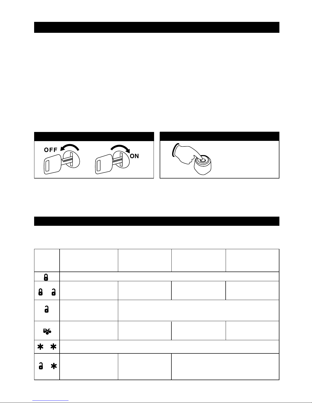
23
Stage 2: Remote Start Operation Programming
In this mode you will program the type of engine starting detection you want to use in your installation. There are
3 types available:
1. Tachometer (RPM) Detection: (Most reliable and recommended) This type of detection requires a hard wire
connection to the vehicles ignition coil.
2. Voltage Detection: This method detects the drop and rise in the battery voltage when the vehicle is started
by remote. This type of detection requires a solid main power input connection but it does not require any
additional hard wire connections.
3. Elapsed Timer: This method is the easiest for installation but is not always the best method for year round
usage (Summer and Winter). To operate this method, you will program a specific time window for the
remote start unit to crank the engine. Battery strength, environment and the aging process of the vehicle may
require the timer to reset from time to time or season to season.
Entering Stage 2 Remote Start Operation Programming
One Chirp Two Chirps Three Chirps Four Chirps
Button LED One Pulse LED Two Pulses LED Three Pulses LED Four Pulses
(Factory Default Setting)
Remote Start Operation and Feature Programming (Stage 2)
9X + 1X (Hold)
Step 3
Remote Start Feature Programming
Use the transmitter buttons as illustrated to adjust the features required. Keep repressing the transmitter button that
relates to the feature you want to adjust until the correct amount of chirps/beeps is heard. Move on to the next feature.
Exit the programming mode (3 long chirps and 3 parking light flashes to confirm exit)
Remote Start Using
Tachometer/RPM Checking
RPM Learning
Start Timer:
0.6 second (1 chirp)
0.8 second (2 chirps)
1.4 second (5 chirps)
2.0 second (8 chirps)
1.0 second (3 chirps)
1.6 second (6 chirps)
3.0 second (9 chirps)
1.2 second (4 chirps)
1.8 second (7 chirps)
4.0 second (10
chirps)
Step 2
Remote Start Using
Voltage Checking
Remote Start Using
Fixed Crank Timer
Low Check Level
Default for Tach Checking
High Check Level
Default for Voltage
Checking
Start or Stop the System for Testing and Adjusting
Turn the ignition switch from the OFF position to the
ON position 3 times leaving it in the OFF position the
third time.
Step 1
3X
+
+
Without Shock Sensor
Test Mode
With Shock Sensor
Test Mode
Before 15 seconds has passed, push and release the valet
switch 9 times then push the valet switch a tenth time and
hold it down until 5 short chirps/beeps + 1 long chirp/beep
is heard then release it. You are now in Stage 2 Remote
Start Feature Programming Mode.
-
Page 24
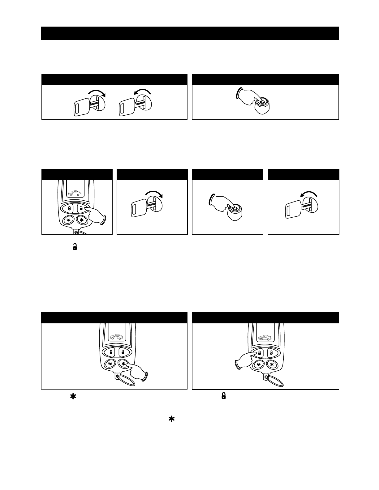
24
Remote Start Operation and Feature Programming
Remote Start Using Tachometer/RPM Checking
Important Note: You must program the “Tach Signal” before trying to remote start.
Turn the ignition switch from the OFF position to the
ON position 3 times leaving it in the Off position the
third time.
OFF
ON
3X
Step 1
Before 15 seconds has passed, push and release the
valet switch 9 times then push the valet switch a tenth
time and hold it down until 5 short chirps/beeps + 1
long chirp/beep is heard then release it.
9X + 1X (Hold)
Step 2
Start the vehicle’s engine
with the ignition key (while
the engine is running the
parking lights and the LED
should be flashing. If they
are not you need to recheck your tachometer
White/Red wire
connection).
ON
Step 4
START
Press and hold the valet
switch for 2 seconds until
you hear a long chirp and
the LED light will be
constant for two seconds.
The RPM signal is learned.
Step 5
Turn OFF the ignition to
stop the engine.
Remember, you are still in
programming mode.
Once you complete Step 6,
you can adjust and test
“Check Level” beginning
with Step 7.
OFF
Step 6
Press the ( ) button twice on the transmitter to start
the vehicle. If everything is correct, the engine will
crank and fire without over-running or under-running
the starter. If all things seem correct, press the ( )
twice to stop the engine from running. If a cranking
problem is noticed, move to Step 9 to adjust the crank
detection feature otherwise follow Step 8 and get out of
the programming mode.
Press the ( ) button on the transmitter to get out of the
programming mode. You will hear 3 long chirps and get
3 parking light flashes for confirmation.
Step 7 Step 8
Press and release the
transmitter button once.
The LED will flash once and
you will hear 1 chirp to
indicate the system in
features “RPM Learning
mode”.
Step 3
Page 25
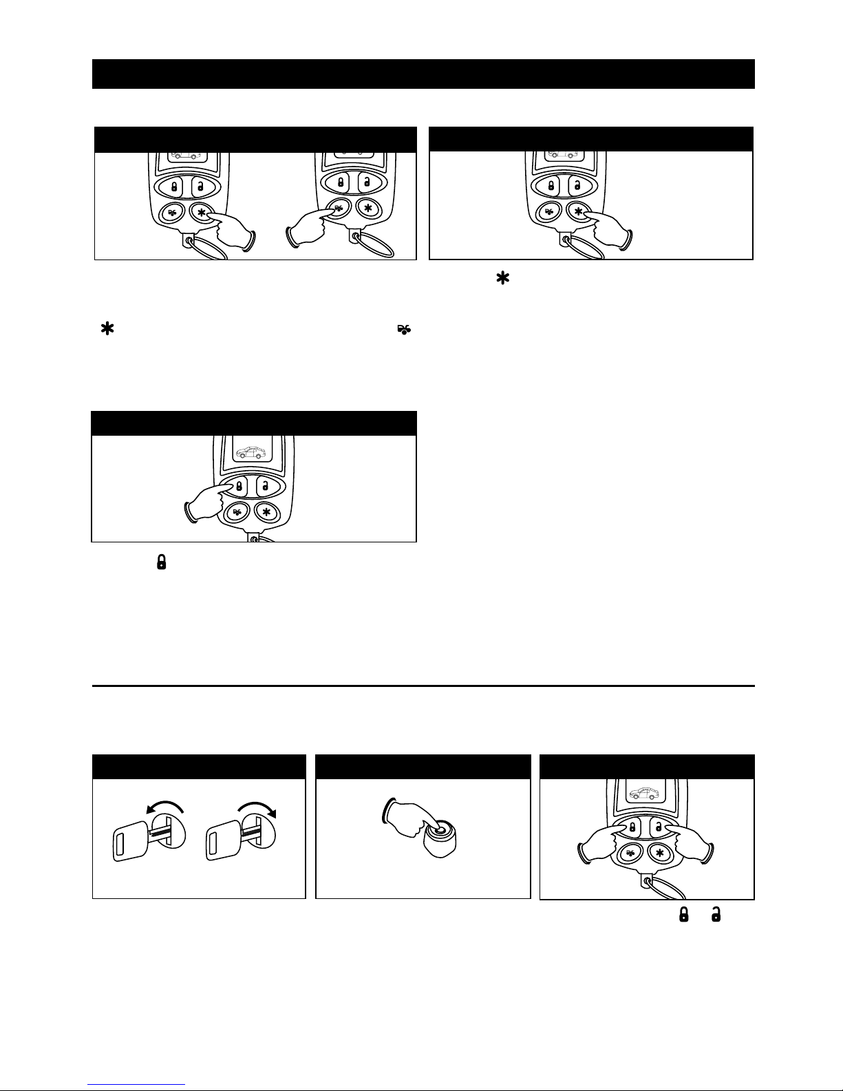
Remote Start Using Voltage Checking
Important Note: The default “Check Level” for Voltage Checking Mode is “High Check Level”.
Turn the ignition switch from the
OFF position to the ON position 3
times leaving it in the Off position
the third time.
OFF
ON
3X
Step 1
Before 15 seconds has passed, push
and release the valet switch 9 times
then push the valet switch a tenth time
and hold it down until 5 short
chirps/beeps + 1 long chirp/beep is
heard then release it.
9X + 1X (Hold)
Step 2
Remote Start Operation and Feature Programming
Remote Start Using Tachometer/RPM Checking (continued)
Press the ( ) button twice on the transmitter to start
the engine by remote. Setting the crank detection to
High should have solved the over-cranking problem.
Step 10
Note: If the crank detection level is set to High and the
engine still will not start consistently due to a short
crank time, it is suggested that you reprogram the unit
to use another type of detection (either voltage or timer)
to get the engine to start consistently.
25
Press and release the ( )
buttons once at the same time to set
the Remote Start using Voltage
Checking.
The LED will flash twice
and you will hear 2 chirps to confirm
this setting.
Step 3
+
If the engine crank time is too short (engine did not
successfully start before the starter quit cranking) you
may need to adjust the crank detection level. Press the
( ) twice to disengage the remote starter. Press the ( )
button on the transmitter to change the crank detection
level from Low to High. You will hear 2 chirps/beeps to
indicate the feature has been changed to the High
selection.
Step 9 (Crank Time Too Short)
Press the ( ) button on the transmitter to get out of the
programming mode. You will hear 3 long chirps and get
3 parking light flashes for confirmation.
Step 11
Note: If the crank detection level is set to High and the engine still will not start consistently due to a short crank
time. It is suggested that you reprogram the unit to use another type of detection (either voltage or timer) to get
the engine to start consistently.
Page 26
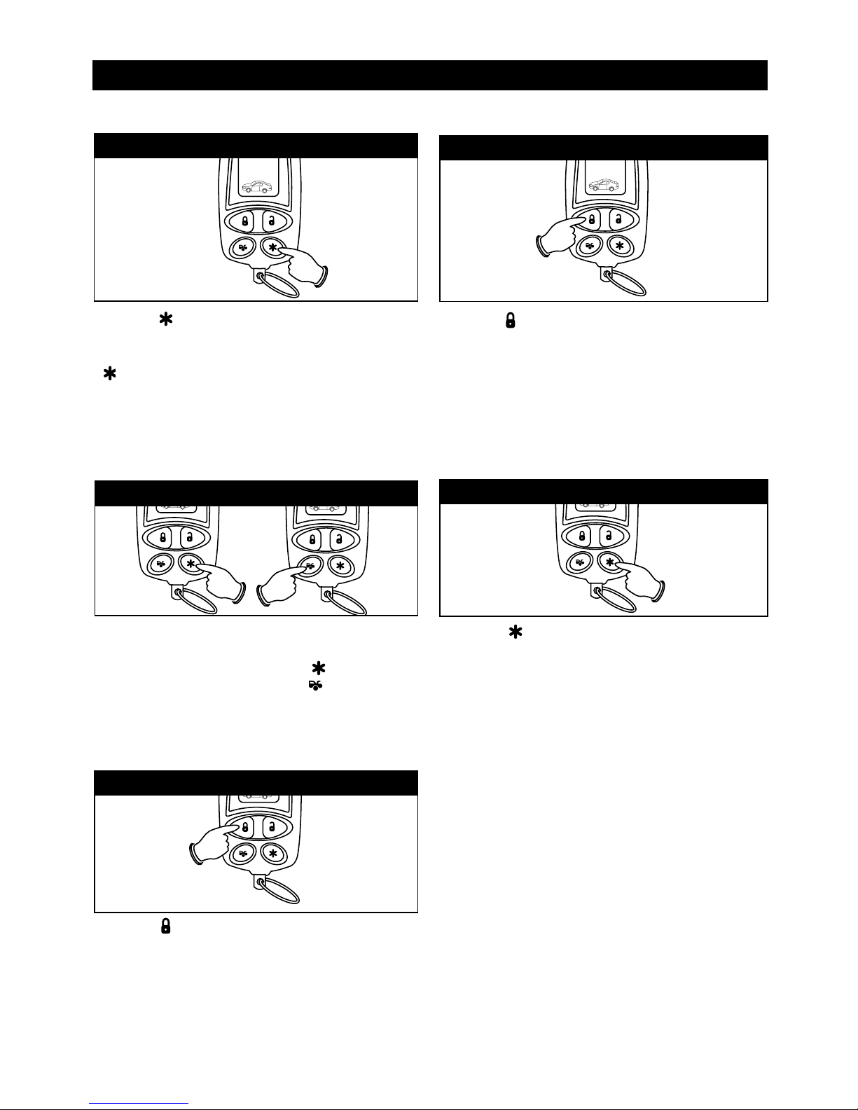
26
Remote Start Operation and Feature Programming (Continued)
Remote Start Using Voltage Checking (continued)
Press the ( ) button on the transmitter to get out of the
programming mode. You will hear 3 long chirps and get
3 parking light flashes for confirmation.
Step 5
Press the ( ) button twice on the transmitter to start
the vehicle. If everything is correct, the engine will
crank and start. If all things seem correct, press the
( ) twice to stop the engine from running. If the
engine cranks too long or shuts down after the vehicle
has been started move to Step 6 to adjust the checking
voltage feature otherwise follow Step 5 and get out of
the programming mode.
Step 4
If the engine cranks too long (engine is successfully
started but the starter is still cranking) you may need
to adjust the check level. Press the ( ) twice to stop
the engine from running.
Press the ( ) button on the
transmitter to change the crank check level from High to
Low. You will hear 1 chirp/beep to indicate the feature
has been changed to the Low selection.
Step 6 (Crank Time Too Long)
Press the ( ) button twice on the transmitter to start
the engine by remote. Setting the crank detection to
Low should have solved the over-cranking problem.
Step 7
Press the ( ) button on the transmitter to get out of
the programming mode. You will hear 3 long chirps and
get 3 parking light flashes for confirmation.
Step 8
Note: If the crank detection level is set to Low and the engine still will not start consistently due to a short crank
time. It is suggested that you reprogram the unit to use another type of detection (either voltage or timer) to get
the engine to start consistently.
Page 27
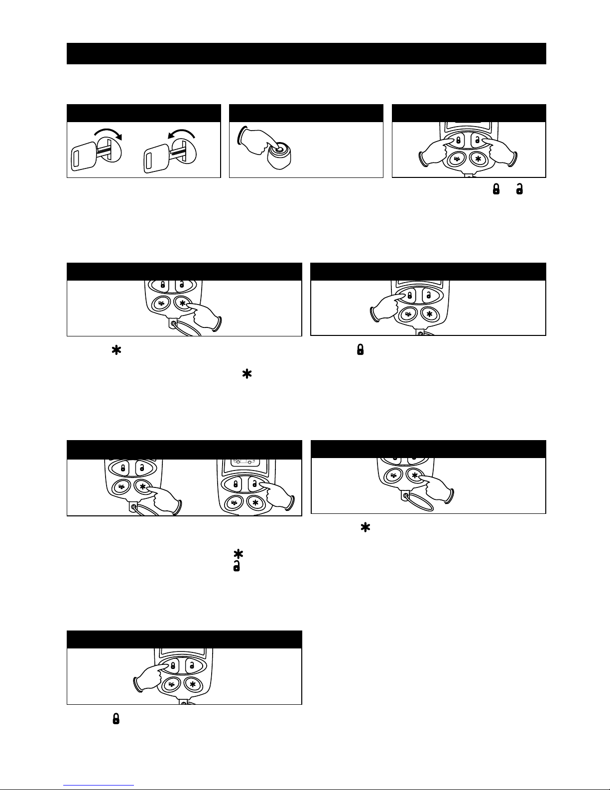
Turn the ignition switch from the
OFF position to the ON position 3
times leaving it in the OFF position
the third time.
OFF
ON
3X
Step 1
Before 15 seconds has passed, push
and release the valet switch 9 times
then push the valet switch a tenth time
and hold it down until 5 short
chirps/beeps + 1 long chirp/beep is
heard then release it.
9X + 1X (Hold)
Step 2
Step 4
Remote Start Using Fixed Crank Timer
If you have selected Elapsed Timer, you may be required to program 1 additional feature as follows.
Remote Start Operation and Feature Programming
Press the ( ) button twice on the transmitter to start the
vehicle. If everything is correct, the engine will crank and
start. If all things seem correct, press the ( ) twice to
stop the engine from running. If the
engine did not
successfully run before the starter quit cranking
move to
Step 6 to adjust the cranking timer. Otherwise follow Step
5 and exit the programming mode.
Press and release the ( )
buttons at the same time once to set
the “Fixed Crank Timer”.
The LED
will flash three times and you will
hear 3 chirps to confirm this setting.
Step 3
+
Press the ( ) button on the transmitter to get out of the
programming mode. You will hear 3 long chirps and get
3 parking light flashes for confirmation.
Step 5
If the engine crank time is too short (engine did not
successfully run before the starter quit cranking) you may
need to adjust the crank time. Press the ( ) twice to
disengage the remote starter. Press the ( ) button on the
transmitter to increase the amount of time the starter
cranks (refer to the chart on Page 23 for cranking times).
You will hear corresponding chirps/beeps to indicate the
feature has been changed to a different cranking time.
Step 6 (Engine Shuts Down)
Press the ( ) button twice on the transmitter to start
the engine by remote. Resetting the crank timer should
have solved the problem.
Step 7
Press the ( ) button on the transmitter to get out of the
programming mode. You will hear 3 long chirps and get
3 parking light flashes for confirmation.
Step 8
27
Page 28
28
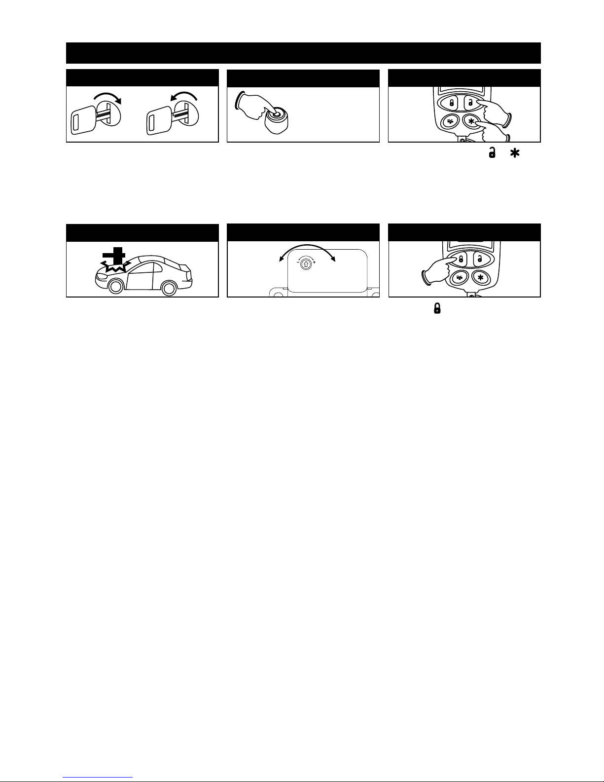
Shock Sensor Testing and Adjustment
Increase
Decrease
A light impact to the vehicle will
activate the warn-away (first stage
shock sensor / Zone 1), the system
will emit a short chirp.
A more forceful impact will activate
the full alarm (second stage shock
sensor / Zone 4), the system will
emit a long chirp.
Using a small screw driver to adjust
the sensitivity. Turn the screw to the
“-” direction decreases the
sensitivity. Turn the screw to the “+”
direction increased the sensitivity.
Continue to test the shock sensor
until the proper sensitivity is
reached.
Step 4
Step 5
OFF
ON
3X
Turn the ignition switch from the
OFF position to the ON position 3
times leaving it in the Off position
the third time.
Step 1
Before 15 seconds has passed, push
and release the valet switch 9 times
then push the valet switch a tenth
time and hold it down until 5 short
chirps/beeps and 1 long chirp/beep
is heard then release it.
9X + 1X (Hold)
Step 2
Press and release the ( )
buttons at the same time twice to
enter the Shock Sensor Test mode,
there will be a 2 chirp confirmation.
Step 3
+
Press the ( ) button on the
transmitter to get out of the
programming mode. You will hear 3
long chirps and get 3 parking light
flashes for confirmation.
Step 6
Page 29
29
LED Shutdown Mode
Flashes
1 (-) Safety Shutdown Input (Hood)
1. Close the Hood
2. Check White/Black Wire Connection (Black 8-Pin Mini)
1. Set the Hand Brake
(+) Safety Shutdown Input (Brake) 2. Check White/Violet Wire Connection (Black 8-Pin Mini)
2 or Neutral Safety Switch Input Fail 3. Move the Enable Toggle Switch to “On” Position (If Installed)
4. Move the gear selector to “Park”/ “Neutral” Position
5. Check Black/White Wire Connection (Black 8-Pin Mini)
3 No RPM (Engine Checking Tach) Check White/Red Wire Connection
Low Voltage (Engine Checking Voltage) Program the “Check Level” from “Hi Check Level” to
“Low Check Level”
5 Over-Rev
6 System Timed-Out
7 Transmitter
8 Tach Signal has Not Been Learned Check Tach Signal Feature Programming
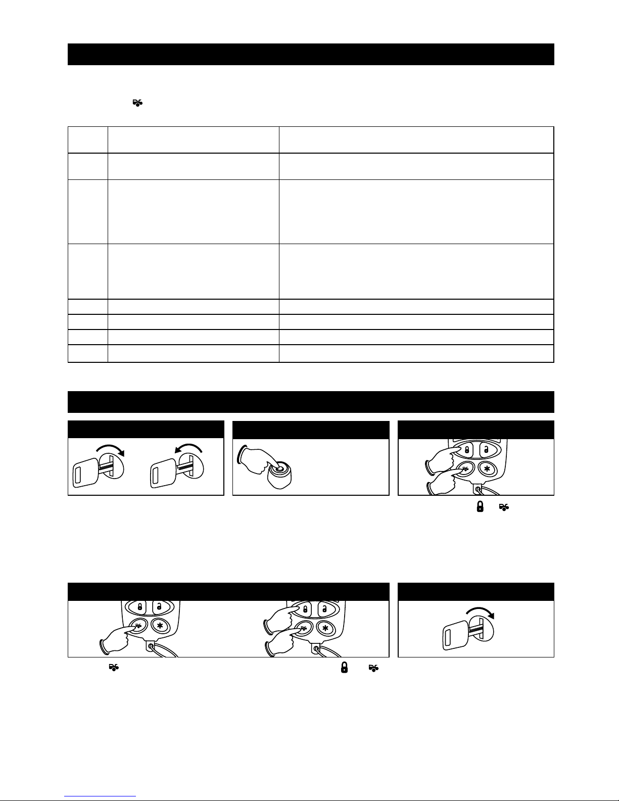
The unit has the ability to report the cause of the last shutdown of the remote start system.
1. Turn the Ignition switch to “On” position.
2. Press the ( ) button on the transmitter.
3. The LED will now report the last system shutdown by flashing for 3 cycles in the following grouped patterns:
Shutdown Diagnostics
Returning to Factory Default Settings
ON
Turn On the Ignition 3 long chirps and
3 flashes of the parking lights will
confirm exit of the programming mode.
Note: Waiting 15 seconds will also
exit the programming mode.
Step 5
Press the button first, then within 3 seconds press and hold the and
buttons at the same time on the transmitter for 6 seconds. There will be six
confirmation chirps with 3 long chirps to confirm the system Remote Start
Operation and Feature Programming 1 and 2 programming all returns to
factory default setting.
OFF
ON
3X
Turn the ignition switch from the
OFF position to the ON position 3
times leaving it in the Off position
the third time.
Step 1
Before 15 seconds has passed, push
and release the valet switch 11 times
then push the valet switch a twelfth
time and hold it down until 6 short
chirps/beeps and 1 long chirp/beep
is heard then release it.
11X + 1X(Hold)
Step 2
Press and hold the ( ) buttons at
the same time for 5 seconds, there will
be 6 short confirmation chirps and 3
long chirps/beeps to confirm the system
“Alarm Feature 1, 2 and 3 Programming
return to factory default settings.
Step 3
+
Step 4
Page 30

30
Caution!
The following procedure must be performed after the installation of the Remote Start Device. It is the
responsibility of the installing technician to complete these tests. Failure to test the unit in the following manner may
result in personal injury, property damage or both.
1. Test the “Brake” Shutdown Circuit:
With the vehicle in Park (P), start the vehicle using the remote transmitter. Once the engine is running, press the
brake pedal. The vehicle should shut down immediately. If the vehicle continues to run, check the brake circuit
“White/Violet” wire.
2. Test the “Hood Pin” Shutdown Circuit:
Start the vehicle using the remote transmitter. Once the engine is running, pull the hood release and raise the
hood. The vehicle should shut down immediately. If the vehicle continues to run, check the hood pin
“White/Black” wire connection.
3. Neutral Start Safety Test:
A. Set the vehicle parking brake.
B. Block the drive wheels to prevent vehicle movement.
C.
Sitting in the vehicle, turn the ignition switch to the “On” or “Run” position, but do not start the engine.
D. Step on the brake pedal and shift the gear selector into Drive (D).
E. Put you foot over the brake pedal but do not press down on it. Be ready to step on the brake to shut down the
Remote Start Device.
F. Start the vehicle using remote transmitter.
a. If the starter does not engage, the test is complete.
b.
If the starter engages, immediately step on the brake pedal to shut down the system, recheck your “Violet” wire
(White 6-Pin, Starter Output) connection. The heavy-gauge “Violet” wire must be connected to the ignition switch
side of the Neutral Start Switch. If the vehicle you are working on does not have an Electrical Neutral Safety Switch,
it will be necessary to reconfigure the Remote Start Wiring to accommodate this vehicle. The information
concerning the Mechanical Neutral Safety Switch provided in this manual will help you to determine if the vehicle
you are working on has this type of safety switch. It will also provide alternate wiring methods to accommodate
this situation.
Remote Start: Testing Your Installation
Page 31
31
Remote Start: Testing Your Installation
P
R
N
2
1
Optional Enable Switch
Ignition
Electronic Control Module (ECM)
Solid State,
Do Not Measure Resistance
Black/White Wire
Neutral Safety Switch
Black 8-Pin
Mini Connector
Key-In Sensor Circuits:
If the vehicle you are working on does not have or you cannot locate the ECM reference wire, there are two alternatives
available. Although not preferred, the vehicle Key-In Sensor may be reconfigured to allow a margin of safety and will
prevent the vehicle with a Mechanical Neutral Start Switch from starting in gear. We advise that you maintain the factory
circuit whenever possible. The following two circuits may be used only if the above circuit is not available.
Note: When completing an installation using either one of the following key-in sensor circuits methods, if the operator
inserts the ignition key while the vehicle is running under the control of the Remote Start, the vehicle will shut down. This
must be explained to the operator as it is in contrast to the normal operation of the vehicle utilizing an electrical neutral
start switch and is inconsistent with the user’s manual.
Method 1: Will allow the safety required for the remote start unit and prevent the vehicle from starting while in any
gear other than Park or Neutral while the key is in the ignition cylinder. However, if the key is left in the ignition
switch and the door is left opened, the added relay will be energized causing a 150mA drain on the battery.
Method 2: Will allow the safety required for the remote start unit and prevent the vehicles from starting while in any
gear other than Park or Neutral while the key is in the ignition cylinder. However, the original factory key-in chime
module will not alert the operator that the key has been left in the ignition switch. These methods should be
carefully considered before altering the vehicle's wiring and must be fully explained to the consumer.
Mechanical Neutral Safety Switch Considerations:
Mechanical neutral safety switch configurations differ slightly in that they do not offer the same level of safety when
installing a remote start device. Often when the ignition switch is turned off while the gear selector is in any position other
than park or neutral, the mechanical function will not allow the key to be turned to the start position or be removed from
the ignition cylinder. This configuration prevents mechanical operation while the vehicle is in gear but offers no
consideration for electrical operation. Because of this potential problem, this installation requires the additional connection
of a safety wire from the remote start device to the vehicle “Park/Neutral ECM” input or the vehicle key-in sensor. This
connection will prevent remote start operation if the key if left in the ignition switch regardless of the gear selector position.
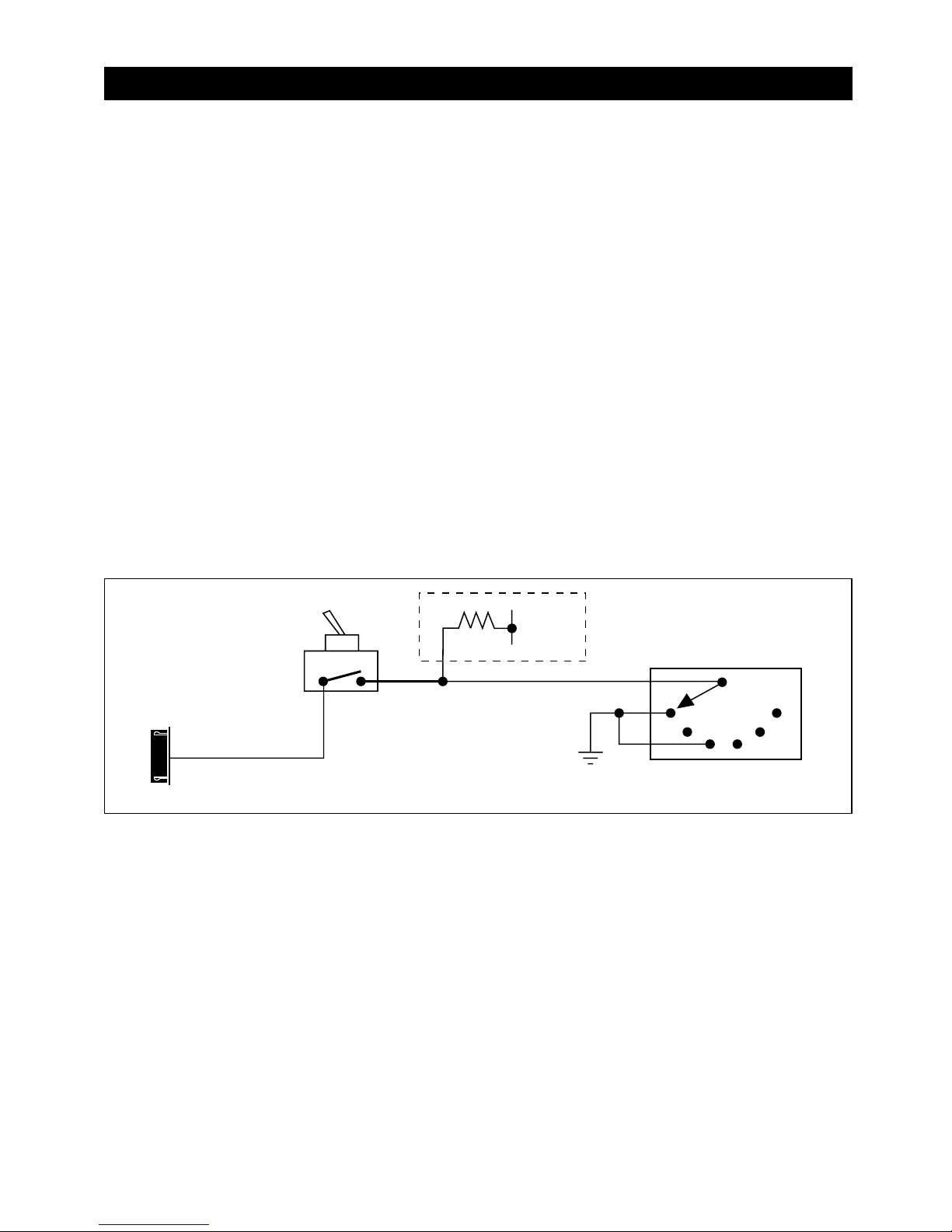
Park Neutral ECM Input:
The Park/Neutral ECM input is the preferred method of installation. This not only maintains the integrity of the
factory circuit, it is also the easiest to install, providing the vehicle you are working on has this ECM input. The
installation required for this application (shown below), indicates in the slight reconfiguration of the control switch
wiring. Shown is a typical GM Park/Neutral ECM input circuit. To connect the Remote Start unit to the GM
Park/Neutral ECM input follow these steps:
1.
Locate the Orange/Black reference wire in the “C2” connector found at the ECM is GM B Body vehicles or, locate the
equivalent reference wire in the vehicle you are installing the Remote Start Unit in.
2. Connect the Black/White Neutral Safety Switch Wire from the Black 8-Pin Mini connector to this reference wire.
Note: If the optional remote start enable toggle switch is installed, connect the one side the enable switch to this
reference wire and connect the other side of the enable switch to the “Black/White” Neutral Safety Switch Wire of the
Remote Start unit. The diagram below shows a typical GM B Body ECM reference wire and how it is to be connected
to the Remote Start Unit.
Page 32
Remote Start: Testing Your Installation
87
87a
86
85
30
Driver's Door
Pin Switch
+12 V
Key in Chime Module
Ignition Key In Sensor
Switch Closes with Key
In Ignition Cylinder
To Hood Pin Switch Safety Shut Down
Safety
IN4003
Black/White Wire
Neutral Safety Switch
Black 8-Pin
Mini Connector
Method 1
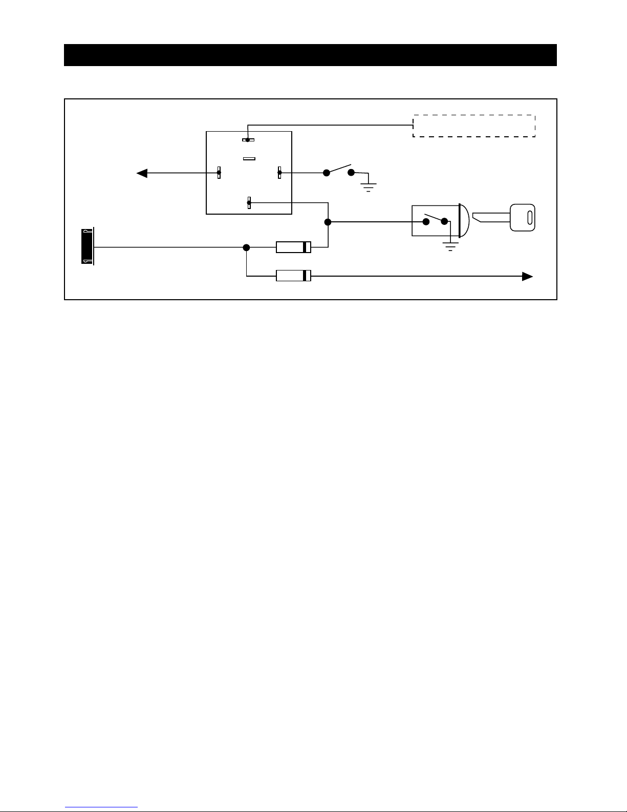
To Connect to the Key-In Sensor using Method 1 follow these steps:
A. Locate the control wire that connects the drivers door pin switch to the key-in sensor switch.
B. Cut this wire and connect the ignition cylinder side to chassis ground.
C. Locate the key-in sensor switch wire that connects the chime module to the ignition cylinder.
D. Cut this wire and connect the ignition cylinder side to terminal 30 of P&B VF45F11 or equivalent relay.
E. Connect the cathode (striped) side of a 4003 series diode to this same wire, and connect the (non-striped) side to
the Negative Safety Input Wire (White/Black of the Remote Start Unit).
F. Connect terminal 86 of the relay to a fused +12 volt constant battery source.
G. Connect terminal 87 of the relay to the Chime Module side of the previously cut wire in Step D.
H. Connect terminal 85 of the relay to the Driver’s Door side of the pin switch wire previously cut in Step B.
Note: A second 4003 series diode may be required to maintain the integrity of the hood open, shut down circuit. If this
is the case, it must be installed as shown in the diagram above. The anode (non stripped) side must be connected to the
WHITE/BLACK wire of the Remote Start Unit. The cathode (striped) side must be connected to the hood pin switch.
32
Page 33
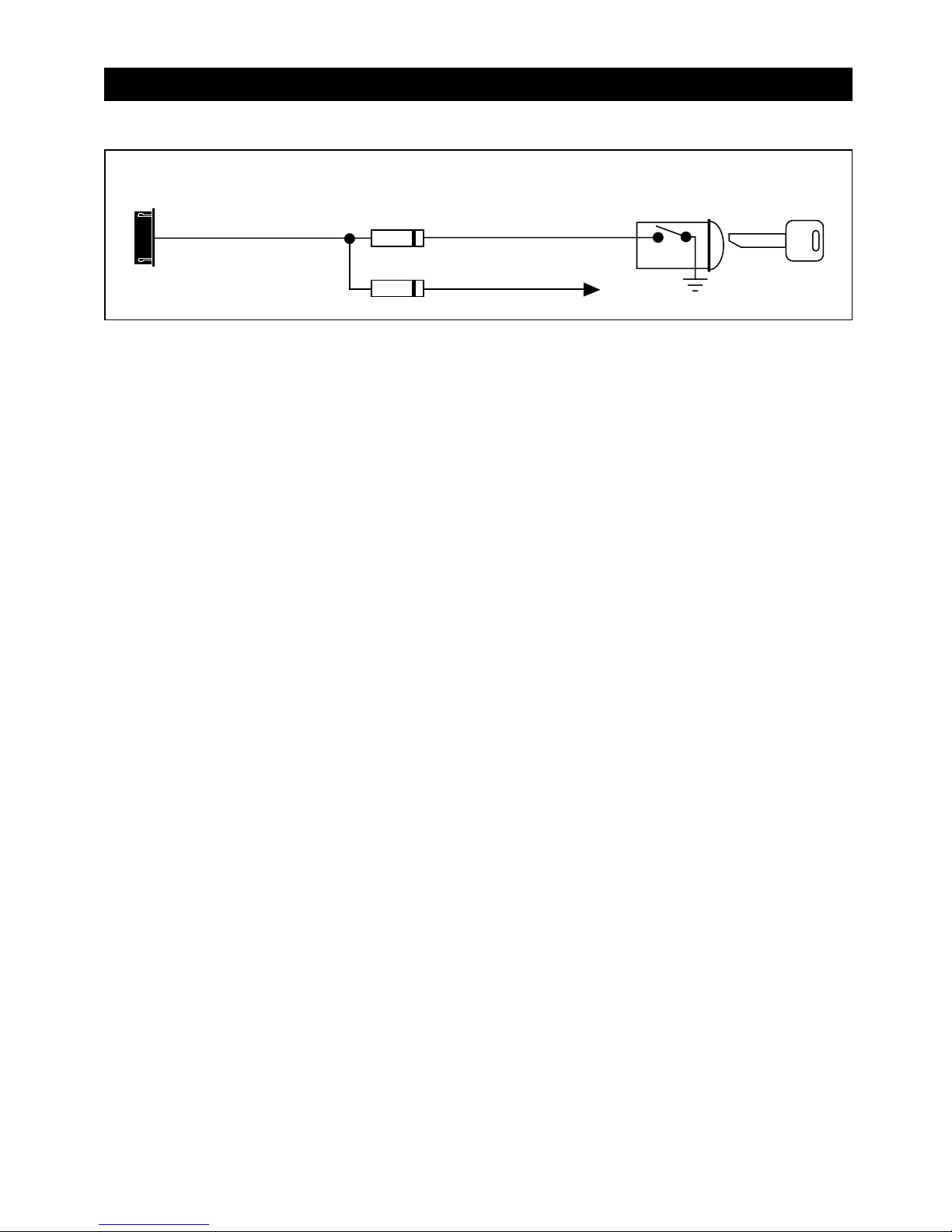
Remote Start: Testing Your Installation
Ignition Key In Sensor Switch Closes
with Key In Ignition Cylinder
To Hood Pin Switch
Safety Shut Down
Safety
IN4003
Black/White Wire
Neutral Safety Switch
Black 8-Pin
Mini Connector
Method 2
To Connect to the Key-In sensor as shown in Method 2 follow these steps:
A. Locate the control wire that connects the driver’s door pin switch to the key-in sensor switch.
B. Cut this wire and connect the ignition cylinder side to chassis ground.
C. Locate the key-in sensor switch wire that connects the chime module to the ignition cylinder.
D. Cut this wire and connect the ignition cylinder side to the Remote Start Negative Safety Shut Down Wire
WHITE/BLACK, using a 4003 series diode as shown above.
Note: A second 4003 series diode may be required to maintain the integrity of the hood open, shut down circuit. If this
is the case, it must be installed as shown in the diagram above. The anode (non-stripped) side must be connected to the
WHITE/BLACK wire of the Remote Start Unit. The cathode (striped) side must be connected to the hood pin switch.
AFTER THE CONNECTION OF THE NEUTRAL START SAFETY WIRE AS INDICATED IN ANY OF THE PREVIOUS
ALTERNATE CONFIGURATIONS, THIS CIRCUIT MUST BE TESTED FOR OPERATION. Retest by following the steps
outlined in NEUTRAL START SAFETY TEST in this manual.
33
Page 34
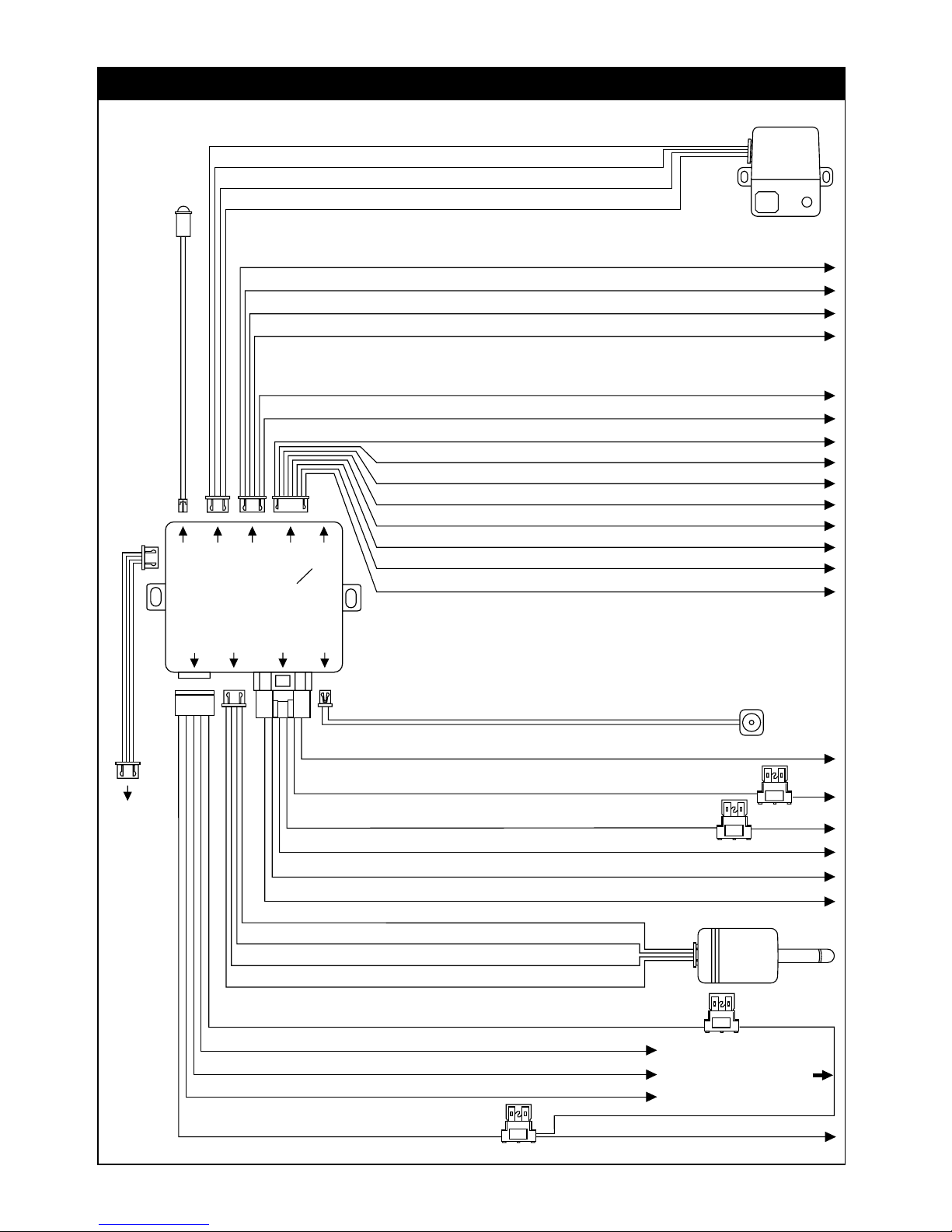
Valet Switch
Violet Wire: Starter Output
Data Adapter Cable
Brown Wire: ACC / Heater Output
Red Wire: +12 V Input (Battery)
Red Wire: +12 V Input (Battery)
Yellow Wire: Ignition 1 Output (Must Connect)
Pink Wire: Ignition 2 Output
20A
20A
5-Pin
White
To Data
Module
4-Pin
Blue
2-Pin
Blue
6-Pin
White
2-Pin
White
4-Pin
White
4-Pin
Tan
4-Pin
White
6-Pin
White
8-Pin
Black
3-Pin
Black
White Wire: Parking Light Relay Output
Black Wire: Ground To Vehicle Frame
Brown Wire: Positive Output to Siren
Red Wire: +12V Input
15A
3A
Red/White Wire: Parking Light Relay Power Input
Red Wire:
Cut this Wire and
Ground it for Ground
Trigger Parking Lights
Green Wire: Warn Away Ground Trigger
Blue Wire: Zone 4 Ground Trigger
Black Wire: Negative Power
Red Wire: +12V Power
Black/White Wire
Black Wire
Black Wire
Black Wire
LED Indicator
(See Door Lock
Connections)
White Wire: (-) 200mA Programmable Output
Dome Light Control Output (Factory Default Setting) or 2 Step Door Unlock or
Factory Security Disarm Signal Output or Ground Output During Start (Crank)
Black/Green Wire: (-) 200mA Timer Control Channel 4 Output / Key Sensor Output
Yellow Wire: (-) 200mA Ignition 3 Control Output
Pink Wire: (-) 200mA Programmable Output
Horn Output (Factory Default Setting) or Factory Security Rearm Signal Output or
Start Status (Shock Sensor Bypass Control) Output
Orange Wire: (-) 500mA Grounded Output when Armed
Gray Wire: (-) 200mA Channel 3 (Trunk) Output
White/Red Wire: Tach Signal Input
Black/White Wire: (-) Neutral Safety Switch Input and (-) Remote Start Toggle Switch Input
White/Violet Wire: (+) Positive Safety Shut Down Input for Brake Switch
Blue Wire: Zone 2 Instant Trigger Ground Input
White/Black WIre: (-) Negative Safety Shut Down Input for Hood Pin Switch
Green Wire: Zone 3 Negative Door Pin Trigger Input
Violet Wire: Zone 3 Positive Door Pin Trigger
White/Blue Wire: (-) Instant Start and Turn Off Input
Wiring Diagram
34
Page 35

35
Page 36

M9A-IM 4-3-07 Rev. C
© Copyright 2007 Magnadyne Corporation
 Loading...