


TECHNICAL NOTICE V1.0
INDUSTRIAL REFRIGERATION UNITS

Identification
Version Date Comments
1.0 01.2009 First Edition
Correspondence
All correspondence regarding our products must provide the serial
number.
The serial number is located on the identification tablet fixed on the refrigeration unit.
LEISTUNGSAUFNAHME
Copyright ©
The reproduction, even partially, of this document is forbidden. No part may be copied in any form, and it may not
be used, edited nor transmitted by any electronic means (photocopy, photography, magnetic supports or other recording processes), without the written authorization of Marksa SA. All rights and particularly reproduction, translation, edition, distribution and also industrial property and recording are reserved.
Marksa SA
Industrial refrigeration units
39, avenue du Technicum
CH-2400 Le Locle
Tél.: +41 32 933 55 55
Fax: +41 32 931 15 65
Page 2 / 100 Technical Notice V1.0 / 01.09

Table of contents
1 Introduction .................................................................................................................... 9
1.1 Foreword............................................................................................................................................ 9
1.1 Typographical conventions.............................................................................................................. 10
1.1.1 Description ....................................................................................................................... 10
1.1.2 Command......................................................................................................................... 10
1.1.3 Procedure......................................................................................................................... 10
1.1.4 Procedure result ............................................................................................................... 10
1.1.5 Cross reference................................................................................................................ 11
1.1.6 List of items ...................................................................................................................... 11
1.1.7 Troubleshooting................................................................................................................ 11
1.1.8 Warning ............................................................................................................................ 12
1.1.9 Recommendation and Note.............................................................................................. 12
2 Generalities ..................................................................................................................15
2.1 Appropriate usage .......................................................................................................................... 15
2.2 Safety and usage warnings ............................................................................................................. 15
2.2.1 Importance of the safety instructions................................................................................ 15
2.2.2 Safety ............................................................................................................................... 15
2.2.3 Graphic symbols............................................................................................................... 16
2.3 Operation ......................................................................................................................................... 17
2.3.1 Basic schematic ............................................................................................................... 17
2.3.2 Principles of operation...................................................................................................... 18
2.3.3 Separated tank and refrigeration units ............................................................................. 19
2.4 Models and available options .......................................................................................................... 20
3 Model CSW 50/65/80 .................................................................................................... 21
3.1 Description....................................................................................................................................... 21
3.1.1 Overall view...................................................................................................................... 21
3.1.2 Technical specifications ...................................................................................................23
3.2 Handling .......................................................................................................................................... 25
3.3 Installation ....................................................................................................................................... 25
3.3.1 Hydraulic connections ......................................................................................................25
3.3.2 Electrical connections....................................................................................................... 25
3.3.3 Filling the reservoir ........................................................................................................... 25
3.4 Commissioning ................................................................................................................................ 26
4 Model CSW 100/150 ..................................................................................................... 27
4.1 Description....................................................................................................................................... 27
4.1.1 Overall view...................................................................................................................... 27
4.1.2 Technical specifications ...................................................................................................28
4.2 Handling .......................................................................................................................................... 30
4.3 Installation ....................................................................................................................................... 30
4.3.1 Hydraulic connections ......................................................................................................30
4.3.2 Electrical connections....................................................................................................... 30
4.3.3 Filling the reservoir ........................................................................................................... 30
4.4 Commissioning ................................................................................................................................ 31
4.5 Specific tuning ................................................................................................................................. 31
4.5.1 Draining the reservoir ....................................................................................................... 31
Technical Notice V1.0 / 01.09 Page 3 / 100

Table of contents
5 Model CSW 200/300 .....................................................................................................33
5.1 Description....................................................................................................................................... 33
5.1.1 Overall view...................................................................................................................... 33
5.1.2 Technical specifications.................................................................................................... 34
5.2 Handling........................................................................................................................................... 36
5.3 Installation........................................................................................................................................ 36
5.3.1 Hydraulic connections ......................................................................................................36
5.3.2 Electrical connections....................................................................................................... 36
5.3.3 Filling the reservoir ........................................................................................................... 36
5.4 Commissioning ................................................................................................................................ 37
5.5 Specific tuning ................................................................................................................................. 37
5.5.1 Draining the reservoir ....................................................................................................... 37
6 Model CSW 400 ............................................................................................................39
6.1 Description....................................................................................................................................... 39
6.1.1 Overall view...................................................................................................................... 39
6.1.2 Technical specifications.................................................................................................... 40
6.2 Handling........................................................................................................................................... 42
6.3 Installation........................................................................................................................................ 42
6.3.1 Hydraulic connections ......................................................................................................42
6.3.2 Electrical connections....................................................................................................... 42
6.3.3 Filling the reservoir ........................................................................................................... 42
6.4 Commissioning ................................................................................................................................ 43
6.5 Specific tuning ................................................................................................................................. 43
6.5.1 Draining the reservoir ....................................................................................................... 43
7 Model CSW 600/800 .....................................................................................................45
7.1 Description....................................................................................................................................... 45
7.1.1 Overall view...................................................................................................................... 45
7.1.2 Technical specifications.................................................................................................... 47
7.2 Handling........................................................................................................................................... 49
7.3 Installation........................................................................................................................................ 49
7.3.1 Hydraulic connections ......................................................................................................49
7.3.2 Electrical connections....................................................................................................... 49
7.3.3 Filling the reservoir ........................................................................................................... 49
7.4 Commissioning ................................................................................................................................ 50
7.5 Specific tuning ................................................................................................................................. 50
7.5.1 Draining the reservoir ....................................................................................................... 50
7.6 Close the drainage tap once the reservoir is empty. ....................................................................... 50
8 Model CSW 900/1000/1300/1700 .................................................................................51
8.1 Description....................................................................................................................................... 51
8.1.1 Overall view...................................................................................................................... 51
8.1.2 Technical specifications.................................................................................................... 53
8.2 Handling........................................................................................................................................... 55
8.3 Installation........................................................................................................................................ 55
8.3.1 Hydraulic connections ......................................................................................................55
8.3.2 Electrical connections....................................................................................................... 55
8.3.3 Filling the reservoir ........................................................................................................... 55
8.4 Commissioning ................................................................................................................................ 56
8.5 Specific tuning ................................................................................................................................. 56
8.5.1 Draining the reservoir ....................................................................................................... 56
Page 4 / 100 Technical Notice V1.0 / 01.09

Table of contents
9 Model CSW 2000/2400 ................................................................................................. 57
9.1 Description....................................................................................................................................... 57
9.1.1 Overall view...................................................................................................................... 57
9.1.2 Technical specifications ...................................................................................................59
9.2 Handling .......................................................................................................................................... 61
9.3 Installation ....................................................................................................................................... 61
9.3.1 Hydraulic connections ......................................................................................................61
9.3.2 Electrical connections....................................................................................................... 61
9.3.3 Filling the reservoir ........................................................................................................... 61
9.4 Commissioning ................................................................................................................................ 62
9.5 Specific tuning ................................................................................................................................. 62
9.5.1 Draining the reservoir ....................................................................................................... 62
9.6 Close the drainage tap once the reservoir is empty. ....................................................................... 62
10 Model CSW 3000/3500/4700 ........................................................................................ 63
10.1 Description....................................................................................................................................... 63
10.1.1 Overall view ...................................................................................................................... 63
10.1.2 Technical specifications ................................................................................................... 65
10.2 Handling .......................................................................................................................................... 67
10.3 Installation ....................................................................................................................................... 67
10.3.1 Hydraulic connections ...................................................................................................... 67
10.3.2 Electrical connections....................................................................................................... 67
10.3.3 Filling the reservoir ........................................................................................................... 67
10.4 Commissioning ................................................................................................................................ 68
10.5 Specific tuning ................................................................................................................................. 68
10.5.1 Draining the reservoir ....................................................................................................... 68
10.6 Close the drainage tap once the reservoir is empty. ....................................................................... 68
11 Tuning and maintenance............................................................................................. 69
11.1 Control settings................................................................................................................................ 69
11.1.1 Thermostat ....................................................................................................................... 69
11.2 Maintenance .................................................................................................................................... 71
11.2.1 Periodic maintenance ....................................................................................................... 71
11.2.2 Safety ............................................................................................................................... 71
11.2.3 Maintenance table ............................................................................................................ 71
11.2.4 Weekly maintenance ........................................................................................................71
11.2.5 Monthly maintenance .......................................................................................................71
11.2.6 Annual maintenance......................................................................................................... 72
Technical Notice V1.0 / 01.09 Page 5 / 100

Table of contents
12 Options..........................................................................................................................73
12.1 List of the options............................................................................................................................. 73
12.2 Air filter (A)....................................................................................................................................... 75
12.2.1 Description of the option................................................................................................... 75
12.2.2 Maintenance ..................................................................................................................... 75
12.2.3 Breakdowns...................................................................................................................... 75
12.3 By-pass (J)....................................................................................................................................... 76
12.3.1 Description of the option................................................................................................... 76
12.3.2 Maintenance ..................................................................................................................... 76
12.3.3 Breakdowns...................................................................................................................... 76
12.4 Distributor (D) .................................................................................................................................. 77
12.4.1 Description of the option................................................................................................... 77
12.4.2 Maintenance ..................................................................................................................... 77
12.4.3 Breakdowns...................................................................................................................... 77
12.5 400V power supply (E) .................................................................................................................... 77
12.5.1 Description of the option................................................................................................... 77
12.5.2 Maintenance ..................................................................................................................... 77
12.5.3 Breakdowns...................................................................................................................... 77
12.6 Water-flow controller (F) .................................................................................................................. 78
12.6.1 Description of the option................................................................................................... 78
12.6.2 Maintenance ..................................................................................................................... 78
12.6.3 Breakdowns...................................................................................................................... 78
12.7 Hot gas bypass (G).......................................................................................................................... 79
12.7.1 Description of the option................................................................................................... 79
12.7.2 Thermostat ....................................................................................................................... 80
12.7.3 Maintenance ..................................................................................................................... 81
12.7.4 Breakdowns..................................................................................................................... 81
12.8 Pre-heating kit (H)............................................................................................................................ 82
12.8.1 Description of the option................................................................................................... 82
12.8.2 Maintenance ..................................................................................................................... 82
12.8.3 Breakdowns...................................................................................................................... 82
12.9 Thermal insulation (I) ....................................................................................................................... 83
12.9.1 Description of the option................................................................................................... 83
12.9.2 Maintenance ..................................................................................................................... 83
12.9.3 Breakdowns...................................................................................................................... 83
12.10 Differential thermostat (L) ................................................................................................................ 83
12.10.1 Description of the option................................................................................................... 83
12.10.2 Maintenance ..................................................................................................................... 83
12.10.3 Breakdowns...................................................................................................................... 83
12.11 Chassis sur roulettes (M)................................................................................................................. 83
12.11.1 Description of the option................................................................................................... 83
12.11.2 Maintenance ..................................................................................................................... 83
12.11.3 Breakdowns...................................................................................................................... 83
12.12 Contrôle de niveau (N)..................................................................................................................... 84
12.12.1 Description of the option................................................................................................... 84
12.12.2 Maintenance ..................................................................................................................... 84
12.12.3 Breakdowns...................................................................................................................... 84
12.13 Circuit d’eau sous pression (P)........................................................................................................ 85
12.13.1 Description of the option................................................................................................... 85
12.13.2 Maintenance ..................................................................................................................... 85
12.13.3 Breakdowns..............................................................................................................
12.14 Reinforced pump (R) ....................................................................................................................... 86
12.14.1 Description of the option................................................................................................... 86
12.14.2 Maintenance ..................................................................................................................... 86
12.14.3 Breakdowns...................................................................................................................... 86
12.15 LP/HP safety pressure controllers (S) ............................................................................................. 87
........ 85
Page 6 / 100 Technical Notice V1.0 / 01.09

Table of contents
12.15.1 Description of the option................................................................................................... 87
12.15.2 Maintenance ..................................................................................................................... 87
12.15.3 Breakdowns...................................................................................................................... 88
12.16 Timer (T) .......................................................................................................................................... 88
12.16.1 Description of the option................................................................................................... 88
12.16.2 Maintenance ..................................................................................................................... 88
12.16.3 Breakdowns...................................................................................................................... 88
12.17 Electric valve and solenoid (W) ....................................................................................................... 88
12.17.1 Description of the option................................................................................................... 88
12.17.2 Maintenance ..................................................................................................................... 88
12.17.3 Breakdowns...................................................................................................................... 88
12.18 High temperature alarm (Y) ............................................................................................................. 89
12.18.1 Description of the option................................................................................................... 89
12.18.2 Maintenance ..................................................................................................................... 89
12.18.3 Breakdowns...................................................................................................................... 89
13 Breakdowns.................................................................................................................. 91
13.1 Warnings.......................................................................................................................................... 91
13.2 Checks............................................................................................................................................. 91
13.2.1 Pressure checks ............................................................................................................... 91
13.3 Breakdowns..................................................................................................................................... 92
13.3.1 Le groupe ne fonctionne pas ............................................................................................ 92
14 Appendix....................................................................................................................... 95
14.1 Compliance...................................................................................................................................... 95
14.1.1 Directives.......................................................................................................................... 95
14.1.2 Identification plate ........................................................................................................... 95
14.2 Disposal of the product.................................................................................................................... 96
14.2.1 General remarks............................................................................................................... 96
14.2.2 Preparation....................................................................................................................... 96
14.3 Maintenance sheet ......................................................................................................................... 97
14.4 Technical data sheet........................................................................................................................ 98
14.5 Compliance documents ................................................................................................................... 99
Technical Notice V1.0 / 01.09 Page 7 / 100

Table of contents
Page 8 / 100 Technical Notice V1.0 / 01.09

Chapter contents
This chapter contains basic information on the structure and the specifications of the document, and on
the documentation.
1.1 Foreword
This manual is intended for all users of a Marksa refrigeration unit. It contains all the information necessary for installation, commissioning, periodic maintenance and repair.
This manual was compiled by the Marksa SA company with the same care as your refrigeration unit and
is therefore an inseparable component. If you have any questions or do not completely understand any
point, please contact your retailer immediately or contact us directly.
Introduction 1
Technical Notice V1.0 / 01.09 Page 9 / 100

1 Introduction
1.1 Typographical conventions
The following styles are used in this manual.
1.1.1 Description
This style, use in conjunction with illustration numbers, is preceded with the corresponding numbers:
Example:
(1) First element
(2) Second element
(3) Etc...
1.1.2 Command
Any software command, button, function key, window, icon, option, tab, checkbox, selection box, article,
menu, tool bar, field and section used in this document is represented by a bold italic font.
Example:
The Exit command allows to quit the software.
1.1.3 Procedure
Each procedure step to be carried out step-by-step by the user is preceded by a letter.
Example
A. Open the drawer.
B. Put the microplate into position as shown.
C. Close the drawer.
1.1.4 Procedure result
A procedure result is shown by the following symbol .
Example
A. Click on the Parameters button.
The parameter window is displayed.
Page 10 / 100 Technical Notice V1.0 / 01.09

1.1.5 Cross reference
This style is used to helps the user find complementary information linked to the current subject.
Example:
See section “4.2.4 Sensor Board Positioning” on page 47.
1.1.6 List of items
This style is used in order to display a list of elements.
Example:
•item 1;
•item 2;
•item 3.
1.1.7 Troubleshooting
The complete description of the error message, the explanation and the remedy appear as follows:
Problem
- Explanation, possible cause
Introduction 1
✔ Remedy
Technical Notice V1.0 / 01.09 Page 11 / 100

1 Introduction
1.1.8 Warning
Depending on the importance of the warning and the associated risks, three warning styles are defined.
The safety aspects are used in accordance with the requirements contained in the following norms:
• ANSI Z535.4;
• ISO 3864, ISO 3864-1:2002, and ISO3864-2:2004.
1.1.8.1 Danger
Indicates an imminently hazardous situation which, if not avoided, will result in death or serious injury.
The main risk is shown in capitals under the symbol WARNING .The mention of a risk does not exclude
anyway the presence of subsidiary risks.
Example
ELECTROCUTION
Never touch unisolated electrical wire. A contact with conductors may cause an electrocution.
1.1.8.2 Warning
Used to indicate a potentially hazardous situation which, if not avoided, could result in death or serious
injury.
Example
Always disconnect the power supply cable before working inside the device. A contact with live
conductors may cause an electrocution.
1.1.8.3 Caution
Used to indicate a potentially hazardous situation which, if not avoided, may result in minor or moderate
injury.
Example
If the mirror is broken, do not handle it with unprotected hands because of risks of cut.
The use of the sign CAUTION without triangle means there is a risk of minor damage, but no possible
injury.
Example
The use of other cleaning agents or hard objects may damage the ID-Pipetor EP-5. Do not use
others cleaning agents or products prior to consult Marksa SA and to receive the agreement.
1.1.9 Recommendation and Note
When additional information is necessary and its non-respect conduct to minor inconveniences, recommendations and notes are presented.
1.1.9.1 Recommendation
Used to designate a preferred procedure or a recommended usage. Marksa SA declines any responsibility in case of non-respected recommendations.
Page 12 / 100 Technical Notice V1.0 / 01.09

Example
For more information, contact either your DiaMed AG representative or the manufacturer directly.
1.1.9.2 Note
Used to give a general or purely informative remark.
Example
The housing reassembly must follow the reverse order of the disassembly.
Introduction 1
Technical Notice V1.0 / 01.09 Page 13 / 100

1 Introduction
Page 14 / 100 Technical Notice V1.0 / 01.09

Chapter contents
This chapter contains generic information applicable to all refrigeration unit models. In particular, it
contains instructions concerning safety as well as practical and theoretical information.
2.1 Appropriate usage
The refrigeration unit is intended to be used to maintain the ambient temperature of a machine tool. It
can be only be used by trained and authorised personnel.
The instructions contained in this user manual must be carefully respected, specifically those concerning
safety.
2.2 Safety and usage warnings
2.2.1 Importance of the safety instructions
The safety and protection instructions appearing in this manual must be respected to avoid injury, damage to property and environmental pollution. In the same manner, the legal conditions, accident prevention and environmental protection measures, as well as the technical regulations for guaranteeing
safe and suitable working conditions applicable in your country and on the specific installation site of the
refrigeration unit must be respected.
Generalities 2
The use of the refrigeration unit in any other manner than described in this manual may void the
guarantee.
2.2.2 Safety
Leave free space of at least 0.5m in front of the intake and 1m in front of the exhaust fan.
As the cooling process is reliant on the circulation of air, sufficient space on each side and above
the refrigeration unit must be planned to ensure that the exhaust fan does not repeatedly recycle
the same air.
The maximum allowable ambient temperature is 38°C for the intake.
The minimum acceptable ambient temperature is 5°C. Below this limit, the operation of your refrigeration unit will be disrupted.
Technical Notice V1.0 / 01.09 Page 15 / 100
2 Generalities
2.2.3 Graphic symbols
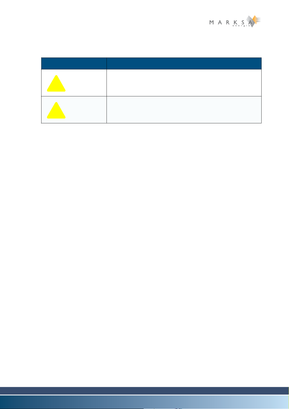
The following symbols may be present on your refrigeration unit:
Symbol Description
Table 2-1: Symbols
Risk of electrocution
Risk of burns
Page 16 / 100 Technical Notice V1.0 / 01.09
2.3 Operation
TH
BP - HP
(7)(6)(4)(3)(2)(1)
(8) (9) (10) (11) (12) (14)(13)
(5)
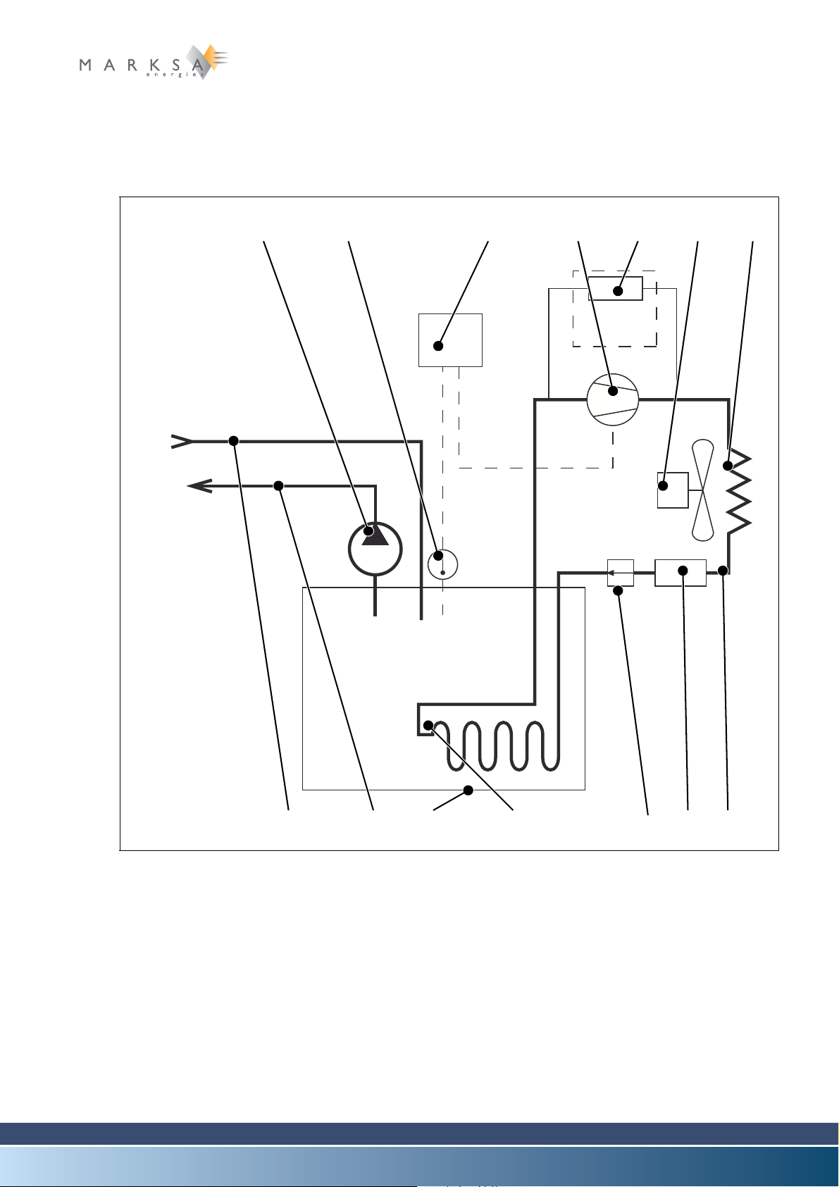
2.3.1 Basic schematic
2.3.1.1 Direct cooling of the tank
Generalities 2
Fig. 2-1 : Basic schematic
Technical Notice V1.0 / 01.09 Page 17 / 100

2 Generalities
2.3.1.2 Legend
(1) Pump
(2) Temperature probe
(3) Thermostat
(4) Compressor
(5) Safety pressure controller (an option on the CSW100)
(6) Exhaust fan
(7) Condenser
(8) Temperate water inlet
(9) Cold water outlet
(10) Reservoir
(11) Evaporator
(12) Pressure regulator
(13) Dehumidifier
(14) Cooling circuit
2.3.2 Principles of operation
The whole range of water chillers supply chilled water (9) continuously at a constant temperature.
The chilling is accomplished in the following manner: An HFC refrigerant of either R134A (tetrafluoroethane) or R407C types is compressed (4) then chilled in a condenser (7).
A pressure regulator (12) causes a drop in pressure which leads to a drop in temperature. The drop in
temperature is transmitted to the water contained in the reservoir (19) through a heat exchanger (11).
The cold water leaves the reservoir (9) to chill the end use equipment and then returns back to the reservoir (8).
Page 18 / 100 Technical Notice V1.0 / 01.09

2.3.3 Separated tank and refrigeration units
TH
HPBP
(7)(6)(4)(3)(2)(1)
(8) (9) (10) (11) (12) (14)(13)
(5)
For refrigeration units of greater capacity, the refrigerant liquid returned is stored in a reservoir (10) then
pumped (1) and chilled (11) before being returned back to the cooling circuit (8)..
Generalities 2
Fig. 2-2 : Basic schematic
Technical Notice V1.0 / 01.09 Page 19 / 100
2 Generalities
2.4 Models and available options
The CSW range of industrial water chillers covers several models, classified according to their capacities
and available options.
The following models are currently available:
Model Capacity
CSW 50 0.5 kW 134A CSW 800 7.8 kW 407C
CSW 65 0.65 kW 134A CSW 900 9.3 kW 407C
CSW 80 0.8 kW 134A CSW 1000 9.7 kW 407C
CSW 100 1 kW 134A CSW 1300 12 kW 407C
CSW 150 1.5 kW 134A CSW 1700 16.4kW 407C
CSW 200 3 kW 134A CSW 2000 20 kW 407C
CSW 300 3 kW 134A CSW 2400 24 kW 407C
CSW 400 4 kW 407C CSW 3000 30 kW 407C
CSW 600 6 kW 407C CSW 3500 35 kW 407C
Table 2-2: List of models
Various options are available.
Refrigerant
gas
Model Capacity
See section “12.1 List of the options” on page 73.
The options are referenced as initials in the product name, just after the reference to its class.
Refrigerant
gas
Example
CSW 100 NRV
With:
N : Water-level control
R : Reinforced pump
V : Visual water-level indicator
Page 20 / 100 Technical Notice V1.0 / 01.09
Chapter contents
(1)
(2)
(3)
This chapter contains information specific to the CSW 50, CSW 65 and CSW 80 models. It covers all
topics associated with installation, commissioning, tuning and maintenance of these models.
For reasons of clarity, only the CSW 80 model is described in the current chapter. However, all
of the explanations apply in a similar fashion to the CSW 50 and CSW 65 models.
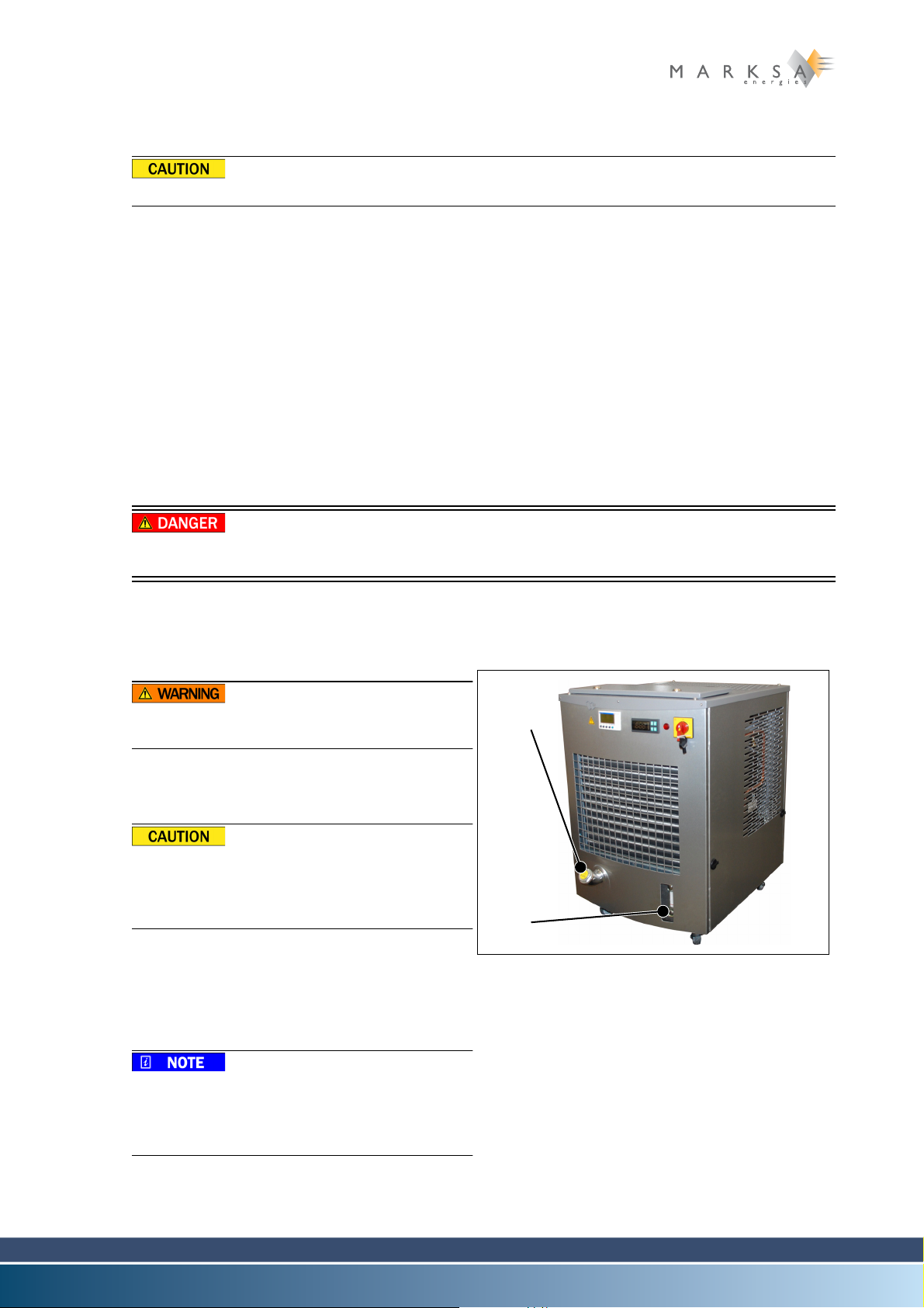
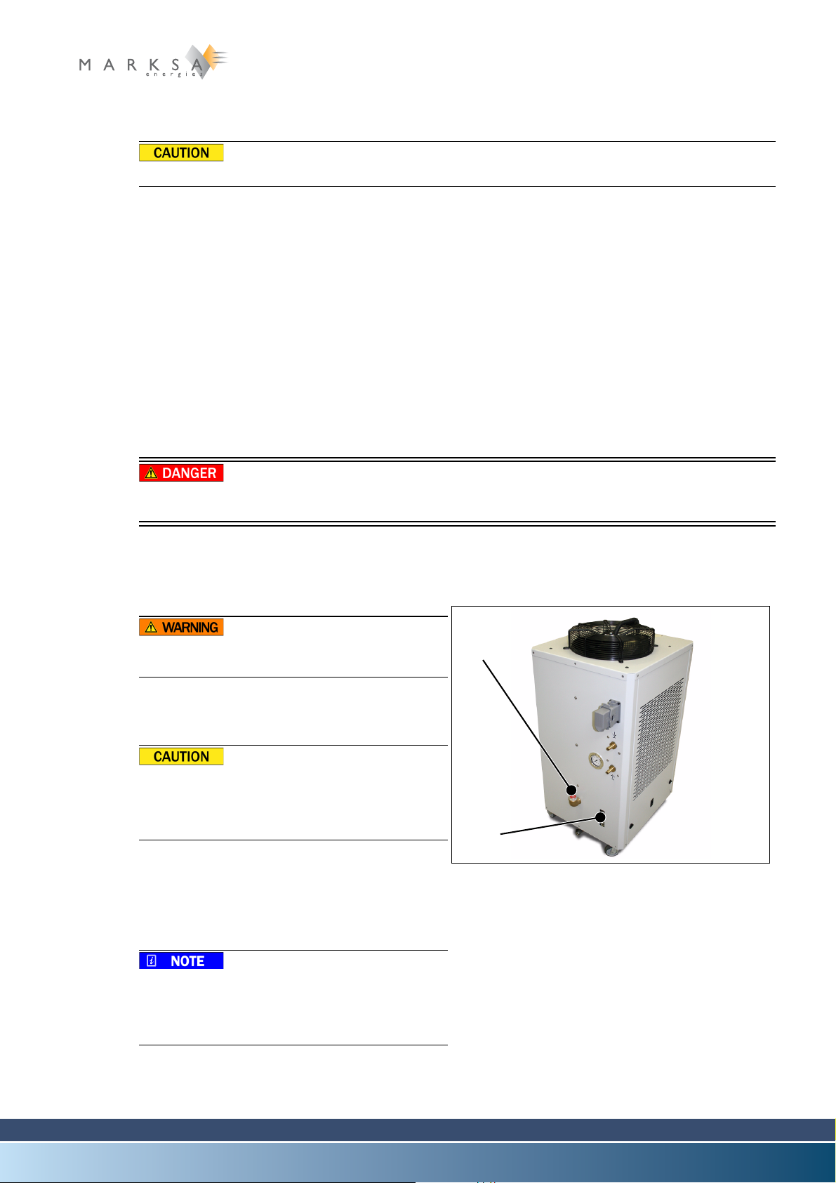
3.1 Description
3.1.1 Overall view
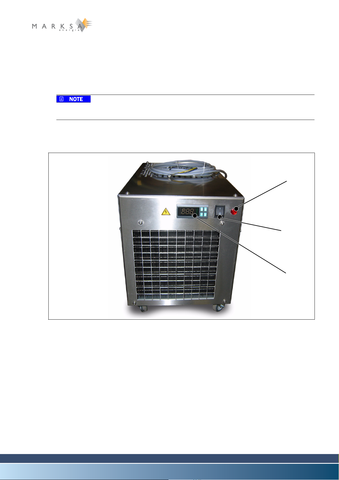
Model CSW 50/65/80 3
Fig. 3-1 : CSW 80 type chiller (front view)
(1) Running pilot lamp
(2) Main power switch
(3) Thermostat display
Technical Notice V1.0 / 01.09 Page 21 / 100
3 Model CSW 50/65/80
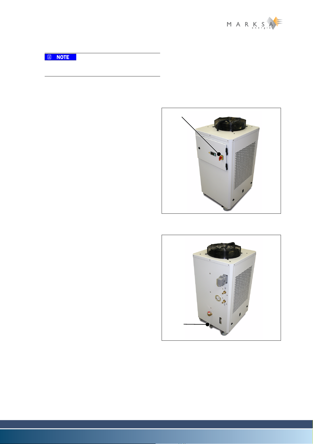
(4)
(5)
(7)
(8)
(6)
Fig. 3-2 : CSW 80 type chiller (rear view)
(4) Cooling liquid outlet
(5) Cooling liquid return inlet
(6) Refilling port
(7) Visual water-level indicator
(8) Electric power connector
Page 22 / 100 Technical Notice V1.0 / 01.09
3.1.2 Technical specifications
3.1.2.1 Standard operating parameters
Description Units CSW 50 CSW 65/80
Refrigerant Type R134A R134A
Refrigerating capacity kW 0.5 0.8
Power consumption kW 0.23 0.41
Heat load kW 0.75 1.2
Inlet temperature °C 22 22
Outlet temperature °C 20 20
Flow rate l/min 8 8
Maximum input temperature °C 38 38
3.1.2.2 Electrical data
Model CSW 50/65/80 3
Description Units CSW 50 CSW 65/80
Power input kW 0.4 0.6
Maximum amperage A 2.5 3
Start-up amperage A 7 10
Line fuse A T 10 10
Power supply V x ph x Hz 230 x 1 x 50 230 x 1 x 50
3.1.2.3 Air condenser
Description Units CSW 50 CSW 65/80
Flow rate m3/h 245 580
Exhaust fan diameter mm 200 254
Power input W 5 16
Ampere rating A 0.2 0.58
Power supply V x ph x Hz 230 x 1 x 50 230 x 1 x 50
Evaporator
Description Units CSW 50 CSW 65/80
Composition COPPER COPPER
Flow rate l/min 8 8
Technical Notice V1.0 / 01.09 Page 23 / 100

3 Model CSW 50/65/80
Hydraulic circuit
Description Units CSW 50 CSW 65/80
Flow rate l/min 8 8
Total p r e s sure bar 0.4 0.4
Power input kW 0.16 0.16
Amperage A 0.70 0.70
Rotation t/min 2900 2900
Power supply V x ph x Hz 230 x 1 x 50 230 x 1 x 50
Stainless steel reservoir l 7 7
Inlet/outlet couplings 3/4’’ 3/4’’
Dimensions
Description Units CSW 50 CSW 65/80
Width mm 305 305
Height mm 320 320
Depth mm 560 560
Weight kg 35 35
Other characteristics
Description Units CSW 50 CSW 65/80
Standard colour Stainless steel Stainless steel
Sound rating
dB(A)
49 49
ISO 3741 – Lp
Page 24 / 100 Technical Notice V1.0 / 01.09
3.2 Handling
Fig. 3-3 : Filler cap
(1)
(2)
The unit must be transported flat and must not sustain any shocks.
3.3 Installation
The unit is normally installed close to the machine being cooled, as indicated on these installation plans.
During the installation, allow for a free space of about 0.5m around the refrigeration unit. This distance
must be 1m in front of the exhaust fan. With these precautions, both ventilation and maintenance access
will be made easier.
3.3.1 Hydraulic connections
Except where specifications state otherwise, the connections between the refrigeration unit and the machine being cooled can be made with pipes with a cross-section diameter at least equal to that indicated
in the technical characteristics.
See section “3.1.2 Technical specifications” on page 23.
3.3.2 Electrical connections
Model CSW 50/65/80 3
ELECTROCUTION
The machine cabinet must be disconnected from power while connecting the cables.
Power cable .............................................installed with a 3m length
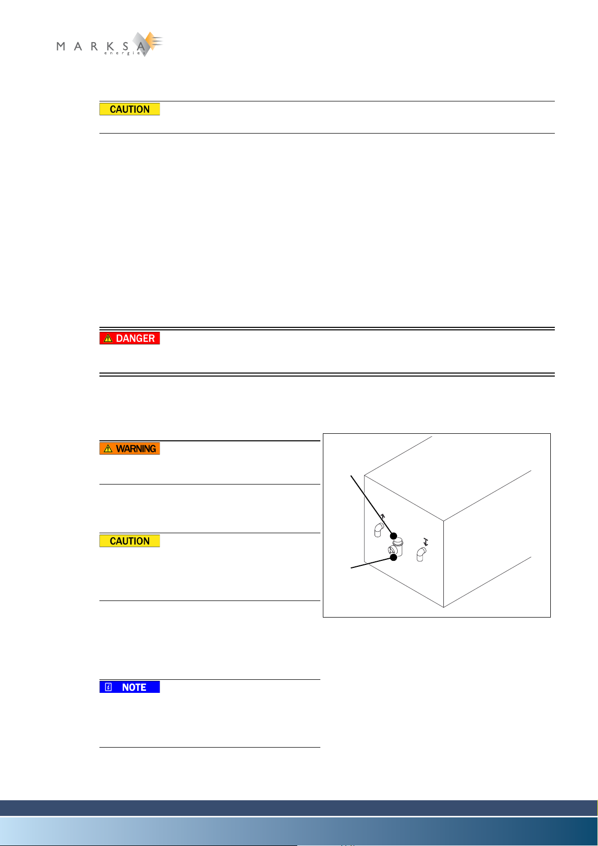
3.3.3 Filling the reservoir
The liquids used are not suitable for human
consumption.
A. Prepare a mixture of water and 30% ethylene gly-
col.
Do not use anti-freeze intended for motor vehicles.
Marksa recommends ANTIFROGEN N antifreeze.
B. Unscrew the cap (1).
C. Fill the reservoir to somewhere between the mini-
mum and maximum levels of the indicator (2).
D. Screw the cap back on.
(or according to customer specifications)
A certain volume of the fluid is used to fill the
machine's circuit. Pay attention to the level
when starting up the machine and top up as
necessary.
Technical Notice V1.0 / 01.09 Page 25 / 100

3 Model CSW 50/65/80
Fig. 3-4 : Engaging
(1)
3.4 Commissioning
The unit has been checked, tuned and tested in
our workshops.
A. Make the hydraulic and electrical connections.
B. Fill the reservoir with liquid.
C. Start up the machine (1).
D. Check the rotation direction of the pump and the
exhaust fan.
Page 26 / 100 Technical Notice V1.0 / 01.09

Chapter contents
(1) (2) (3) (4) (5) (6)
This chapter contains information specific to the CSW 100 and CSW 150 models. It covers all topics associated with installation, commissioning, tuning and maintenance of these models.
For reasons of clarity, only the CSW 100 model is described in the current chapter. However, all
of the explanations apply in a similar fashion to the CSW 150 model.
4.1 Description
4.1.1 Overall view
Model CSW 100/150 4
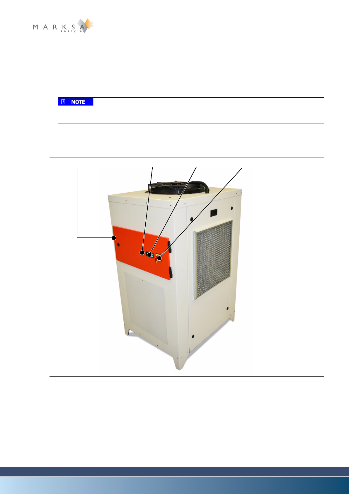
Fig. 4-1 : CSW 100 type chiller
(1) Lifting ring
(2) Breakdown indicator lamp (red)
(3) Water-level indicator lamp (orange, optional)
(4) Thermostat display
(5) Purge button
(6) Main power switch
Technical Notice V1.0 / 01.09 Page 27 / 100

4 Model CSW 100/150
4.1.2 Technical specifications
4.1.2.1 Standard operating parameters
Description Units CSW 100 CSW 150
Refrigerant Type R134A R134A
Refrigerating capacity kW 1.20 1.50
Power consumption kW 0.53 0.53
Heat load kW 1.73 1.73
Inlet temperature °C 22 22
Outlet temperature °C 20 20
Flow rate l/min 8 8
Maximum input temperature °C 38 38
4.1.2.2 Electrical data
Description Units CSW 100 CSW 150
Power input kW 0.8 1.0
Maximum amperage A 6.5 6.5
Start-up amperage A 16 21
Line fuse A T 10 10
Power supply V x ph x Hz 230 x 1 x 50 230 x 1 x 50
4.1.2.3 Air condenser
Description Units CSW 100 CSW 150
Flow rate m3/h 580 580
Exhaust fan diameter mm 254 254
Power input W 16 16
Ampere rating A 0.58 0.58
Power supply V x ph x Hz 230 x 1 x 50 230 x 1 x 50
Evaporator
Description Units CSW 100 CSW 150
Composition COPPER COPPER
Flow rate l/min 8 8
Page 28 / 100 Technical Notice V1.0 / 01.09

Model CSW 100/150 4
Hydraulic circuit
Description Units CSW 100 CSW 150
Flow rate l/min 8 8
Total pressure bar 0.4 0.4
Power input kW 0.16 0.16
Amperage A 0.70 0.70
Rotation t/min 2900 2900
Power supply V x ph x Hz 230 x 1 x 50 230 x 1 x 50
Stainless steel reservoir l 8 8
Inlet/outlet couplings 3/4’’ 3/4’’
Dimensions
Description Units CSW 100 CSW 150
Width mm 370 370
Height mm 385 385
Depth mm 600 600
Weight kg 51 51
Other characteristics
Description Units CSW 100 CSW 150
Standard colour Stainless steel Stainless steel
Sound rating
dB(A)
49 49
ISO 3741 – Lp
Technical Notice V1.0 / 01.09 Page 29 / 100

4 Model CSW 100/150
Fig. 4-2 : Filler cap
(1)
(2)
4.2 Handling
The unit must be transported flat and must not sustain any shocks.
4.3 Installation
The unit is normally installed close to the machine being cooled, as indicated on these installation plans.
During the installation, allow for a free space of about 0.5m around the refrigeration unit. This distance
must be 1m in front of the exhaust fan. With these precautions, both ventilation and maintenance access
will be made easier.
4.3.1 Hydraulic connections
Except where specifications state otherwise, the connections between the refrigeration unit and the machine being cooled can be made with pipes with a cross-section diameter at least equal to that indicated
in the technical characteristics.
See section “4.1.2 Technical specifications” on page 28.
4.3.2 Electrical connections
ELECTROCUTION
The machine cabinet must be disconnected from power while connecting the cables.
Power cable ............................................ installed with a 3m length
4.3.3 Filling the reservoir
The liquids used are not suitable for human
consumption.
A. Prepare a mixture of water and 30% ethylene gly-
col.
Do not use anti-freeze intended for motor vehicles.
Marksa recommends ANTIFROGEN N antifreeze.
B. Unscrew the cap (1).
C. Fill the reservoir to somewhere between the mini-
mum and maximum levels of the indicator (2).
D. Screw the cap back on.
(or according to customer specifications)
Page 30 / 100 Technical Notice V1.0 / 01.09
A certain volume of the fluid is used to fill the
machine's circuit. Pay attention to the level
when starting up the machine and top up as
necessary.

4.4 Commissioning
Fig. 4-3 : Engaging
(1) (2)
The unit has been checked, tuned and tested in
our workshops.
A. Make the hydraulic and electrical connections.
B. Fill the reservoir with liquid.
C. Start up the machine (1).
D. Check the rotation direction of the pump and the
exhaust fan.
Model CSW 100/150 4
4.5 Specific tuning
4.5.1 Draining the reservoir
A. Disconnect the outlet pipe.
B. Put the output pipe into an empty container.
C. Press the push button (2) on the front of the unit.
D. Release the button when the pump emits air.
Technical Notice V1.0 / 01.09 Page 31 / 100

4 Model CSW 100/150
Page 32 / 100 Technical Notice V1.0 / 01.09
Chapter contents
(1) (2) (3) (4)
(5) (6)
This chapter contains information specific to the CSW 200 and CSW 300 models. It covers all topics associated with installation, commissioning, tuning and maintenance of these models.
For reasons of clarity, only the CSW 200 model is described in the current chapter. However, all
of the explanations apply in a similar fashion to the CSW 300 model.
5.1 Description
5.1.1 Overall view
Model CSW 200/300 5
Fig. 5-1 : CSW 200 type chiller
(1) Programmable controller display (optional)
(2) Thermostat display
(3) Breakdown indicator lamp (red)
(4) Main power switch
(5) Refilling port
(6) Visual water-level indicator
Technical Notice V1.0 / 01.09 Page 33 / 100
5 Model CSW 200/300
5.1.2 Technical specifications
5.1.2.1 Standard operating parameters
Description Units CSW 200/300 CSW200E/300E
Refrigerant Type R134A R134A
Refrigerating capacity W 3000 3000
Power consumption W 1355 1355
Heat load W 4355 4355
Inlet temperature °C 25 25
Outlet temperature °C 20 20
Flow rate l/min 8 10
Maximum input temperature °C 38 38
5.1.2.2 Electrical data
Description Units CSW 200/300 CSW200E/300E
Power input kW 1.70 1.70
Maximum amperage A 9 3.25
Start-up amperage A 36 15
Line fuse A T 10 6
Power supply V x ph x Hz 230 x 1 x 50 400 x 3 x 50
5.1.2.3 Air condenser
Description Units CSW 200/300 CSW200E/300E
Flow rate m3/h 700 800
Exhaust fan diameter mm 275 275
Power input W 25 25
Ampere rating A 0.75 0.49
Power supply V x ph x Hz 230 x 1 x 50 400 x 3 x 50
Evaporator
Description Units CSW 200/300 CSW200E/300E
Composition COPPER COPPER
Flow rate l/min 8 10
Page 34 / 100 Technical Notice V1.0 / 01.09
Model CSW 200/300 5
Hydraulic circui
Description Units CSW 200/300 CSW200E/300E
Flow rate l/min 8 10
Total pressure bar 0.40 0.50
Power input kW 0.16 0.25
Amperage A 0.70 0.80
Rotation t/min 2900 2900
Power supply V x ph x Hz 230 x 1 x 50 400 x 3 x 50
Stainless steel reservoir l 21 21
Dimensions
Description Units CSW 200/300 CSW200E/300E
Width mm 435 435
Height mm 580 580
Depth mm 525 525
Weight kg 78 78
Other characteristics
Description Units CSW 200/300 CSW200E/300E
Inlet/outlet couplings mm 13 13
Standard colour Stainless steel Stainless steel
Sound rating
dB(A)
52 52
ISO 3741 – Lp
Technical Notice V1.0 / 01.09 Page 35 / 100
5 Model CSW 200/300
Fig. 5-2 : Filler cap
(1)
(2)
5.2 Handling
The unit must be transported flat and must not sustain any shocks.
5.3 Installation
The unit is normally installed close to the machine being cooled, as indicated on these installation plans.
During the installation, allow for a free space of about 0.5m around the refrigeration unit. This distance
must be 1m in front of the exhaust fan. With these precautions, both ventilation and maintenance access
will be made easier.
5.3.1 Hydraulic connections
Except where specifications state otherwise, the connections between the refrigeration unit and the machine being cooled can be made with pipes with a cross-section diameter at least equal to that indicated
in the technical characteristics.
See section “5.1.2 Technical specifications” on page 34.
5.3.2 Electrical connections
ELECTROCUTION
The machine cabinet must be disconnected from power while connecting the cables.
Power cable ............................................ installed with a 3m length (or according to customer specifica-
5.3.3 Filling the reservoir
The liquids used are not suitable for human
consumption.
A. Prepare a mixture of water and 30% ethylene gly-
col.
Do not use anti-freeze intended for motor vehicles.
Marksa recommends ANTIFROGEN N antifreeze.
B. Unscrew the cap (1).
C. Fill the reservoir to somewhere between the mini-
mum and maximum levels of the indicator (2).
D. Screw the cap back on.
tions)
Page 36 / 100 Technical Notice V1.0 / 01.09
A certain volume of the fluid is used to fill the
machine's circuit. Pay attention to the level
when starting up the machine and top up as
necessary.
5.4 Commissioning
Fig. 5-3 : Engaging
(1)
(2)
Fig. 5-4 : Emptying cap
(2)
The unit has been checked, tuned and tested in
our workshops.
A. Make the hydraulic and electrical connections.
B. Fill the reservoir with liquid.
C. Start up the machine (1).
D. Check the rotation direction of the pump and the
exhaust fan.
Model CSW 200/300 5
5.5 Specific tuning
5.5.1 Draining the reservoir
A. Put a container under the tap (2) or the drainage
plug located under the chiller.
B. Open the drainage tap.
C. Close the drainage tap once the reservoir is emp-
ty.
Technical Notice V1.0 / 01.09 Page 37 / 100

5 Model CSW 200/300
Page 38 / 100 Technical Notice V1.0 / 01.09
Chapter contents
(1) (2) (3) (4)
(5)
(6)
This chapter contains information specific to the CSW 400 model. It covers all topics associated with installation, commissioning, tuning and maintenance of these models.
6.1 Description
6.1.1 Overall view
Model CSW 400 6
Abb. 6-1 : CSW 400 type chiller
(1) Programmable controller display (optional)
(2) Thermostat display
(3) Breakdown indicator lamp (red)
(4) Main power switch
(5) Refilling port
(6) Visual water-level indicator
Technical Notice V1.0 / 01.09 Seite 39 / 100
6 Model CSW 400
6.1.2 Technical specifications
6.1.2.1 Standard operating parameters
Description Units CSW 400
Refrigerant Typ R134A
Refrigerating capacity kW 4000
Power consumption kW 1200
Heat load kW 5200
Inlet temperature °C 24
Outlet temperature °C 20
Flow rate l/min 15
Maximum input temperature °C 38
6.1.2.2 Electrical data
Description Units CSW 400
Power input kW 2.5
Maximum amperage A 7.5
Start-up amperage A 25
Line fuse A T 10
Power supply V x ph x Hz 400 x 3 x 50
6.1.2.3 Air condenser
Description Units CSW 400
Flow rate m3/h 1100
Exhaust fan diameter mm 300
Power input W 140
Ampere rating A 0.6
Power supply V x ph x Hz 230 x 1 x 50
Evaporator
Description Units CSW 400
Composition COPPER
Flow rate l/min 15
Seite 40 / 100 Technical Notice V1.0 / 01.09
Hydraulic circui
Description Units CSW 400
Flow rate l/min 15
Total pressure bar 2.5
Power input kW 0.37
Amperage A 1.80
Rotation t/min 2900
Power supply V x ph x Hz 400 x 3 x 50
Stainless steel reservoir l 35
Inlet/outlet couplings 3/4’’
Dimensions
Description Units CSW 400
Model CSW 400 6
Width mm 620
Height mm 1000
Depth mm 620
Weight kg 160
Other characteristics
Description Units CSW 400
Standard colour RAL RAL 7035
Sound rating
dB(A) 55
ISO 3741 – Lp
Technical Notice V1.0 / 01.09 Seite 41 / 100

6 Model CSW 400
Abb. 6-2 : Filler cap
(1)
(2)
6.2 Handling
The unit must be transported flat and must not sustain any shocks.
6.3 Installation
The unit is normally installed close to the machine being cooled, as indicated on these installation plans.
During the installation, allow for a free space of about 0.5m around the refrigeration unit. This distance
must be 1m in front of the exhaust fan. With these precautions, both ventilation and maintenance access
will be made easier.
6.3.1 Hydraulic connections
Except where specifications state otherwise, the connections between the refrigeration unit and the machine being cooled can be made with pipes with a cross-section diameter at least equal to that indicated
in the technical characteristics.
See section “6.1.2 Technical specifications” on page 40.
6.3.2 Electrical connections
ELECTROCUTION
The machine cabinet must be disconnected from power while connecting the cables.
Power cable ............................................ installed with a 3m length (or according to customer specifica-
6.3.3 Filling the reservoir
The liquids used are not suitable for human
consumption.
A. Prepare a mixture of water and 30% ethylene gly-
col.
Do not use anti-freeze intended for motor vehicles.
Marksa recommends ANTIFROGEN N antifreeze.
B. Unscrew the cap (1).
C. Fill the reservoir to somewhere between the mini-
mum and maximum levels of the indicator (2).
D. Screw the cap back on.
tions)
Seite 42 / 100 Technical Notice V1.0 / 01.09
A certain volume of the fluid is used to fill the
machine's circuit. Pay attention to the level
when starting up the machine and top up as
necessary.

6.4 Commissioning
Abb. 6-3 : Engaging
(1)
Abb. 6-4 : Emptying cap
(2)
The unit has been checked, tuned and tested in
our workshops.
A. Make the hydraulic and electrical connections.
B. Fill the reservoir with liquid.
C. Start up the machine (1).
D. Check the rotation direction of the pump and the
exhaust fan.
Model CSW 400 6
6.5 Specific tuning
6.5.1 Draining the reservoir
A. Put a container under the tap (2) or the drainage
plug located under the chiller.
B. Open the drainage tap.
C. Close the drainage tap once the reservoir is emp-
ty.
Technical Notice V1.0 / 01.09 Seite 43 / 100

6 Model CSW 400
Seite 44 / 100 Technical Notice V1.0 / 01.09

Chapter contents
(1) (2) (3) (4)
This chapter contains information specific to the CSW 600 and CSW 800 models. It covers all topics associated with installation, commissioning, tuning and maintenance of these models.
For reasons of clarity, only the CSW 800 model is described in the current chapter. However, all
of the explanations apply in a similar fashion to the CSW 600 model.
11.1 Description
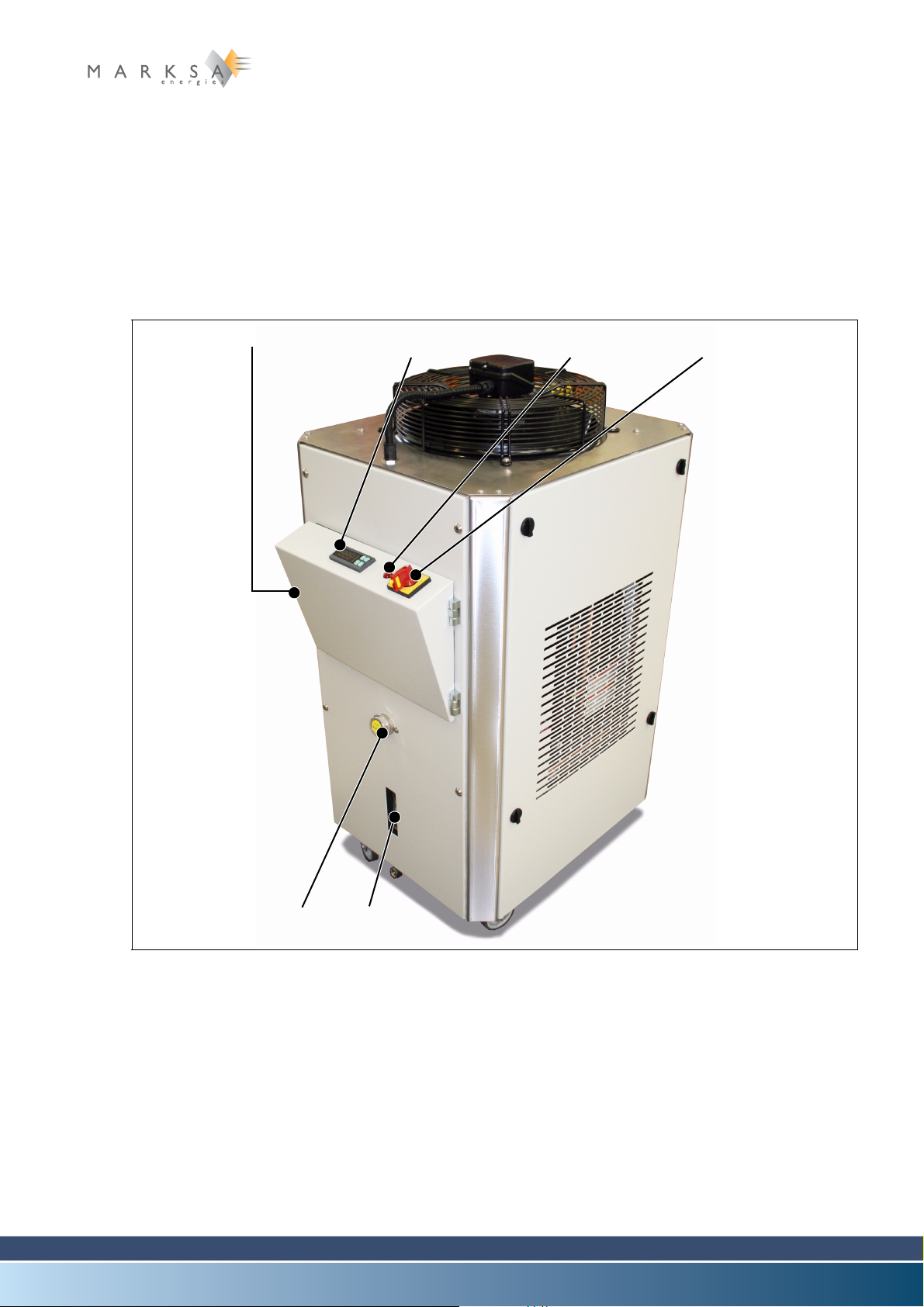
11.1.1 Overall view
Model CSW 600/800 11
Fig. 11-1 : CSW 800 type chiller (front view)
(1) Programmable controller display (optional, visible after opening the door)
(2) Thermostat display
(3) Breakdown indicator lamp (red)
(4) Main power switch
Technical Notice V1.0 / 01.09 Page 69 / 100

11 Model CSW 600/800
(5) (7)(6)
(10)
(9)
(11)
(8)
Fig. 11-2 : CSW 800 type chiller (rear view)
(5) Output circuit pressure gauge (on request)
(6) Electric power connector (on request)
(7) Cooling liquid return inlet
(8) Cooling liquid outlet
(9) Refilling port
(10) Drainage tap
(11) Visual water-level indicator
Page 70 / 100 Technical Notice V1.0 / 01.09

11.1.2 Technical specifications
11.1.2.1 Standard operating parameters
Description Units CSW 600/800
Refrigerant Type R407C
Refrigerating capacity kW 7900
Power consumption kW 1500
Heat load kW 7500
Inlet temperature °C 25
Outlet temperature °C 20
Flow rate l/min 20
Maximum input temperature °C 38
Table 11-1:
11.1.2.2 Electrical data
Model CSW 600/800 11
Description Units CSW 600/800
Power input kW 3
Maximum amperage A 9,5
Start-up amperage A 30
Line fuse A T 10
Power supply V x ph x Hz 400 x 3 x 50
Table 11-2:
11.1.2.3 Air condenser
Description Units CSW 600/800
Flow rate m3/h 1585
Exhaust fan diameter mm 350
Power input W 135
Ampere rating A 0,32
Power supply V x ph x Hz 400 x 3 x 50
Table 11-3:
Evaporator
Description Units CSW 600/800
Composition COPPER
Table 11-4:
Technical Notice V1.0 / 01.09 Page 71 / 100
11 Model CSW 600/800
Description Units CSW 600/800
Flow rate l/min 20
Charge loss bar 0,2
Table 11-4:
Hydraulic circui
Description Units CSW 600/800
Flow rate l/min 20
Total p r e s sure bar 1,5
Power input kW 0,37
Amperage A 1,8
Rotation t/min 2900
Power supply V x ph x Hz 400 x 3 x50
Stainless steel reservoir l 55
Inlet/outlet couplings 3/4 ‘’
Table 11-5:
Dimensions
Description Units CSW 600/800
Width mm 550
Height mm 900
Depth mm 600
Weight kg 11 2
Table 11-6:
Other characteristics
Description Units CSW 600/800
Standard colour RAL 7035
Sound rating
dB(A) 50
ISO 3741 – Lp
Table 11-7:
Page 72 / 100 Technical Notice V1.0 / 01.09
11.2 Handling
Fig. 11-3 : Filler cap
(1)
(2)
The unit must be transported flat and must not sustain any shocks.
11.3 Installation
The unit is normally installed close to the machine being cooled, as indicated on these installation plans.
During the installation, allow for a free space of about 0.5m around the refrigeration unit. This distance
must be 1m in front of the exhaust fan. With these precautions, both ventilation and maintenance access
will be made easier.
11.3.1 Hydraulic connections
Except where specifications state otherwise, the connections between the refrigeration unit and the machine being cooled can be made with pipes with a cross-section diameter at least equal to that indicated
in the technical characteristics.
See section “7.1.2 Technical specifications” on page 71.
11.3.2 Electrical connections
Model CSW 600/800 11
ELECTROCUTION
The machine cabinet must be disconnected from power while connecting the cables.
Power cable .............................................installed with a 3m length (or according to customer specifica-
tions)
11.3.3 Filling the reservoir
The liquids used are not suitable for human
consumption.
A. Prepare a mixture of water and 30% ethylene gly-
col.
Do not use anti-freeze intended for motor vehicles.
Marksa recommends ANTIFROGEN N antifreeze.
B. Unscrew the cap (1).
C. Fill the reservoir to somewhere between the mini-
mum and maximum levels of the indicator (2).
D. Screw the cap back on.
A certain volume of the fluid is used to fill the
machine's circuit. Pay attention to the level
when starting up the machine and top up as
necessary.
Technical Notice V1.0 / 01.09 Page 73 / 100
11 Model CSW 600/800
Fig. 11-4 : Engaging
(1)
Fig. 11-5 : Emptying cap
(2)
11.4 Commissioning
The unit has been checked, tuned and tested in
our workshops.
A. Make the hydraulic and electrical connections.
B. Fill the reservoir with liquid.
C. Start up the machine (1).
D. Check the rotation direction of the pump and the
exhaust fan.
11.5 Specific tuning
11.5.1 Draining the reservoir
A. Put a container under the tap (2) or the drainage
plug located under the chiller.
B. Open the drainage tap.
11.6 Close the drainage tap once the reservoir is empty.
Page 74 / 100 Technical Notice V1.0 / 01.09
Chapter contents
(1) (2)
(3)
(4)
This chapter contains information specific to the CSW 900, CSW 1000, CSW 1300 et CSW 1700models.
It covers all topics associated with installation, commissioning, tuning and maintenance of these models.
For reasons of clarity, only the CSW 1000 model is described in the current chapter. However, all
of the explanations apply in a similar fashion to the CSW 900, CSW 1300 et CSW 1700 models.
11.1 Description
11.1.1 Overall view
Model CSW 900/1000/1300/1700 11
Fig. 11-1 : CSW 1000 type chiller (front view)
(1) Programmable controller display (optional, visible after opening the door)
(2) Thermostat display
(3) Breakdown indicator lamp (red)
(4) Main power switch
Technical Notice V1.0 / 01.09 Page 69 / 100

11 Model CSW 900/1000/1300/1700
(5)
(8)
(6)
(7)
(9)
Fig. 11-2 : CSW 1000 type chiller (rear view)
(5) Electric power connector
(6) Cooling liquid return inlet
(7) Cooling liquid outlet
(8) Visual water-level indicator
(9) Drainage tap
Page 70 / 100 Technical Notice V1.0 / 01.09

11.1.2 Technical specifications
11.1.2.1 Standard operating parameters
Description Units CSW 900/1000 CSW 1300 CSW 1700
Refrigerant Type R407C R407C R407C
Refrigerating capacity kW 9.7 12 16,4
Power consumption kW 2.2 3.5 4.5
Heat load kW 11,9 15,5 20.9
Inlet temperature °C 27 25 27
Outlet temperature °C 20 20 20
Flow rate l/min 20 35 35
Model CSW 900/1000/1300/1700 11
Maximum input temper-
ature
Table 11-1:
11.1.2.2 Electrical data
Description Units CSW 900/1000 CSW 1300 CSW1700
Power input kW 4 4.5 5.5
Maximum amperage A 12 13 16
Start-up amperage A 40 45 50
Line fuse A T 16 16 20
Power supply V x ph x Hz 400 x 3 x 50 400 x 3 x 50 400 x 3 x 50
Table 11-2:
11.1.2.3 Air condenser
Description Units CSW 900/1000 CSW 1300 CSW 1700
Flow rate m3/h 3350 3350 3350
°C 38 38 38
Exhaust fan diameter mm 420 420 420
Power input W 270 270 300
Ampere rating A 0.65 0.65 0.7
Power supply V x ph x Hz 400 x 3 x 50 400 x 3 x 50 400 x 3 x 50
Table 11-3:
Technical Notice V1.0 / 01.09 Page 71 / 100
11 Model CSW 900/1000/1300/1700
Evaporator
Description Units CSW 900/1000 CSW 1300 CSW 1700
Composition AISI 316 AISI 316 AISI 316
Flow rate l/min 20 40 40
Charge loss bar 0,2 0,25 0,25
Table 11-4:
Hydraulic circui
Description Units CSW 900/1000 CSW 1300 CSW 1700
Flow rate l/min 20 35 35
Total pressure bar 2 2,5 2,5
Power input kW 0,37 0,37 0,37
Amperage A 1,8 1,8 1,8
Rotation t/min 2900 2900 2900
Power supply V x ph x Hz 400 x 3 x 50 400 x 3 x 50 400 x 3 x 50
Stainless steel reservoir l 60 60 145
Inlet/outlet couplings 1 “ 1 “ 1 “
Table 11-5:
Dimensions
Description Units CSW 900/1000 CSW 1300 CSW 1700
Width mm 700 700 700
Height mm 1300 1300 1300
Depth mm 850 850 850
Weight kg 230 245 275
Table 11-6:
Other characteristics
Description Units CSW 900/1000 CSW 1300 CSW 1700
Standard colour RAL 7035 7035 7035
Sound rating
ISO 3741 – Lp
Table 11-7:
Page 72 / 100 Technical Notice V1.0 / 01.09
dB(A) 65 65 65
11.2 Handling
Fig. 11-3 : Filler cap
(1)
The unit must be transported flat and must not sustain any shocks.
11.3 Installation
The unit is normally installed close to the machine being cooled, as indicated on these installation plans.
During the installation, allow for a free space of about 0.5m around the refrigeration unit. This distance
must be 1m in front of the exhaust fan. With these precautions, both ventilation and maintenance access
will be made easier.
11.3.1 Hydraulic connections
Except where specifications state otherwise, the connections between the refrigeration unit and the machine being cooled can be made with pipes with a cross-section diameter at least equal to that indicated
in the technical characteristics.
See section “8.1.2 Technical specifications” on page 71.
11.3.2 Electrical connections
Model CSW 900/1000/1300/1700 11
ELECTROCUTION
The machine cabinet must be disconnected from power while connecting the cables.
Power cable .............................................installed with a 3m length (or according to customer specifica-
tions)
11.3.3 Filling the reservoir
The liquids used are not suitable for human
consumption.
A. Prepare a mixture of water and 30% ethylene gly-
col.
Do not use anti-freeze intended for motor vehicles.
Marksa recommends ANTIFROGEN N antifreeze.
B. Unscrew the cap (1).
C. Fill the reservoir to somewhere between the mini-
mum and maximum levels of the indicator (2).
D. Screw the cap back on.
A certain volume of the fluid is used to fill the
machine's circuit. Pay attention to the level
when starting up the machine and top up as
necessary.
Technical Notice V1.0 / 01.09 Page 73 / 100

11 Model CSW 900/1000/1300/1700
Fig. 11-4 : Engaging
(1)
Fig. 11-5 : Emptying cap
(2)
11.4 Commissioning
The unit has been checked, tuned and tested in
our workshops.
A. Make the hydraulic and electrical connections.
B. Fill the reservoir with liquid.
C. Start up the machine (1).
D. Check the rotation direction of the pump and the
exhaust fan.
11.5 Specific tuning
11.5.1 Draining the reservoir
A. Put a container under the tap (2) or the drainage
plug located under the chiller.
B. Open the drainage tap.
C. Close the drainage tap once the reservoir is emp-
ty.
Page 74 / 100 Technical Notice V1.0 / 01.09

Chapter contents
(2) (3) (4)(1)
This chapter contains information specific to the CSW 2000 and CSW 2400 models. It covers all topics
associated with installation, commissioning, tuning and maintenance of these models.
For reasons of clarity, only the CSW 2000 model is described in the current chapter. However, all
of the explanations apply in a similar fashion to the CSW 2400 model.
11.1 Description
11.1.1 Overall view
Model CSW 2000/2400 11
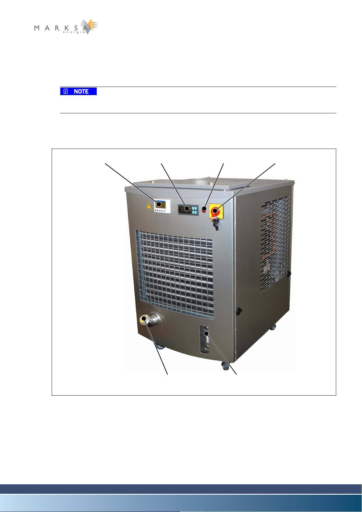
Fig. 11-1 : CSW 2000 type chiller (front view)
(1) Programmable controller display (optional, visible after opening the door)
(2) Thermostat display
(3) Breakdown indicator lamp (red)
(4) Main power switch
Technical Notice V1.0 / 01.09 Page 69 / 100

11 Model CSW 2000/2400
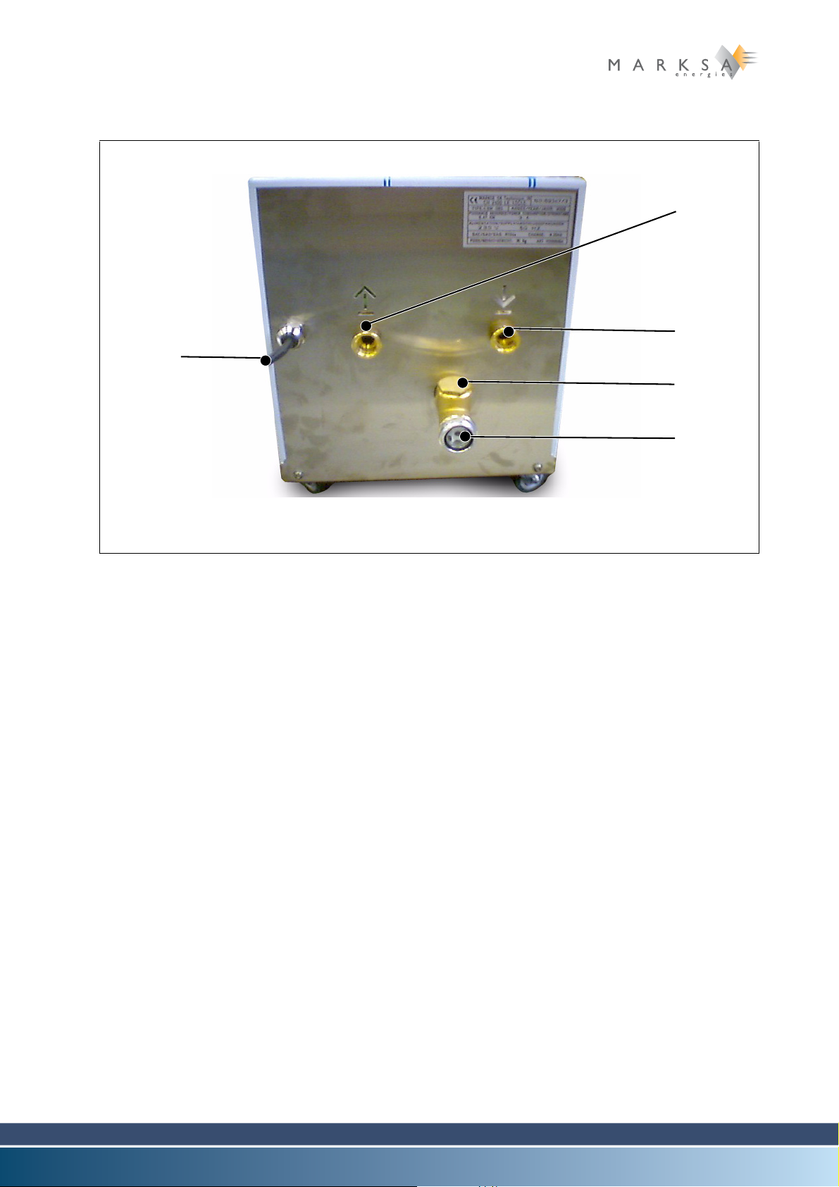
(5)
(6)
(7)
(8)
(9)
Fig. 11-2 : CSW 2000 type chiller (rear view)
(5) Electric power connector (optional)
(6) Output circuit pressure gauge
(7) Cooling liquid outlet
(8) Cooling liquid return inlet
(9) Drainage tap
Page 70 / 100 Technical Notice V1.0 / 01.09
11.1.2 Technical specifications
11.1.2.1 Standard operating parameters
Description Units CSW 2000 CSW 2400
Refrigerant Type R407C R407C
Refrigerating capacity kW 20,0 24,0
Power consumption kW 6,7 7,4
Heat load kW 26,7 31,4
Inlet temperature °C 27 28
Outlet temperature °C 20 20
Flow rate l/min 40 40
Maximum input temperature °C 42 42
11.1.2.2 Electrical data
Model CSW 2000/2400 11
Description Units CSW 2000 CSW 2400
Power input kW 8,0 9,0
Maximum amperage A 16 18
Start-up amperage A 50 60
Line fuse A T 20 20
Power supply V x ph x Hz 400 x 3 x 50
11.1.2.3 Air condenser
Description Units CSW 2000 CSW 2400
Flow rate m3/h 8600 8600
Exhaust fan diameter mm 500 500
Power input W 500 500
Ampere rating A 1,2 1,2
Power supply V x ph x Hz 400 x 3 x 50 400 x 3 x 50
Evaporator
Description Units CSW 2000 CSW 2400
Composition AISI316 AISI316
Flow rate l/min 40 40
Charge loss bar 0,2 0,2
Technical Notice V1.0 / 01.09 Page 71 / 100

11 Model CSW 2000/2400
Hydraulic circui
Description Units CSW 2000 CSW 2400
Flow rate l/min 40 40
Total p r e s sure bar 2 2
Power input kW 0,37 0,37
Amperage A 1,2 1,2
Rotation t/min 2900 2900
Power supply V x ph x Hz 400 x 3 x 50 400 x 3 x 50
Stainless steel reservoir l 145 145
Inlet/outlet couplings 1’’ 1’’
Dimensions
Description Units CSW 2000 CSW 2400
Width mm 700 700
Height mm 1300 1300
Depth mm 1240 1240
Weight kg 305 32
Other characteristics
Description Units CSW 2000 CSW 2400
Standard colour RAL 7035 SFS 7055
Sound rating
dB(A) 71 71
ISO 3741 – Lp
Page 72 / 100 Technical Notice V1.0 / 01.09

11.2 Handling
Fig. 11-3 : Filler cap
(1)
The unit must be transported flat and must not sustain any shocks.
11.3 Installation
The unit is normally installed close to the machine being cooled, as indicated on these installation plans.
During the installation, allow for a free space of about 0.5m around the refrigeration unit. This distance
must be 1m in front of the exhaust fan. With these precautions, both ventilation and maintenance access
will be made easier.
11.3.1 Hydraulic connections
Except where specifications state otherwise, the connections between the refrigeration unit and the machine being cooled can be made with pipes with a cross-section diameter at least equal to that indicated
in the technical characteristics.
See section “9.1.2 Technical specifications” on page 71.
11.3.2 Electrical connections
Model CSW 2000/2400 11
ELECTROCUTION
The machine cabinet must be disconnected from power while connecting the cables.
Power cable .............................................installed with a 3m length (or according to customer specifica-
tions)
11.3.3 Filling the reservoir
The liquids used are not suitable for human
consumption.
A. Prepare a mixture of water and 30% ethylene gly-
col.
Do not use anti-freeze intended for motor vehicles.
Marksa recommends ANTIFROGEN N antifreeze.
B. Unscrew the cap (1).
C. Fill the reservoir to somewhere between the mini-
mum and maximum levels of the indicator (2).
D. Screw the cap back on.
A certain volume of the fluid is used to fill the
machine's circuit. Pay attention to the level
when starting up the machine and top up as
necessary.
Technical Notice V1.0 / 01.09 Page 73 / 100

11 Model CSW 2000/2400
Fig. 11-4 : Engaging
(1)
Fig. 11-5 : Emptying cap
(2)
11.4 Commissioning
The unit has been checked, tuned and tested in
our workshops.
A. Make the hydraulic and electrical connections.
B. Fill the reservoir with liquid.
C. Start up the machine (1).
D. Check the rotation direction of the pump and the
exhaust fan.
11.5 Specific tuning
11.5.1 Draining the reservoir
A. Put a container under the tap (2) or the drainage
plug located under the chiller.
B. Open the drainage tap.
11.6 Close the drainage tap once the reservoir is empty.
Page 74 / 100 Technical Notice V1.0 / 01.09

Chapter contents
(2) (3) (4)(1)
(5) (6)
This chapter contains information specific to the CSW 3000, CSW 3500 and CSW 4700 models. It covers all topics associated with installation, commissioning, tuning and maintenance of these models.
For reasons of clarity, only the CSW 3000 model is described in the current chapter. However, all
of the explanations apply in a similar fashion to the CSW 3500 and CSW 4700 models.
11.1 Description
11.1.1 Overall view
Model CSW 3000/3500/4700 11
Fig. 11-1 : CSW 3000 type chiller (front view)
(1) Programmable controller display (optional, visible after opening the door)
(2) Breakdown indicator lamp (red)
(3) Thermostat display
(4) Main power switch
(5) Output circuit pressure gauge (on request)
(6) Drainage tap
Technical Notice V1.0 / 01.09 Page 69 / 100
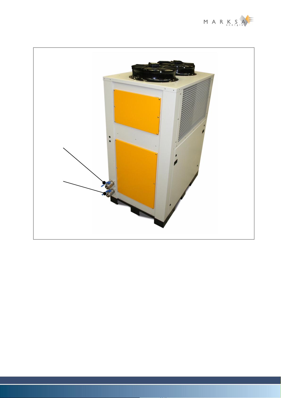
11 Model CSW 3000/3500/4700
(7)
(8)
Fig. 11-2 : CSW 3000 type chiller (rear view)
(7) Cooling liquid outlet
(8) Cooling liquid return inlet
Page 70 / 100 Technical Notice V1.0 / 01.09

11.1.2 Technical specifications
11.1.2.1 Standard operating parameters
Description Units CSW 3000 CSW 3500 CSW 4700
Refrigerant Type R407C R407C R407C
Refrigerating capacity kW 30,0 35,0 47,0
Power consumption kW 8,4 10,7 9,55
Heat load kW 38,4 45,7 56,55
Inlet temperature °C 25 26 26
Outlet temperature °C 20 20 20
Flow rate l/min 75 75 115
Maximum input temperature °C 42 42 42
11.1.2.2 Electrical data
Model CSW 3000/3500/4700 11
Description Units CSW 3000 CSW 3500 CSW 4700
Power input kW 12,0 13,0 15,0
Maximum amperage A 24 26 28
Start-up amperage A 75 80 90
Line fuse A T 30 30 30
Power supply V x ph x Hz 400 x 3 x 50 400 x 3 x 50 400 x 3 x 50
11.1.2.3 Air condenser
Description Units CSW 3000 CSW 3500 CSW 4700
Flow rate m3/h 11000 9200 2 x 8600
Exhaust fan diameter mm 2 x 400 2 x 500 2 x 500
Power input W 2 x 160 2 x 770 2 x 500
Ampere rating A 2 x 0,73 2 x 3,4 2 x 1,2
Power supply V x ph x Hz 230 x 3 x 50 230 x 3 x 50 400 x 3 x 50
Evaporator
Description Units CSW 3000 CSW 3500 CSW 4700
Composition AISI316 AISI316 AISI316
Flow rate l/min 75 75 115
Technical Notice V1.0 / 01.09 Page 71 / 100
11 Model CSW 3000/3500/4700
Hydraulic circui
Description Units CSW 3000 CSW 3500 CSW 4700
Flow rate l/min 75 75 115
Total p r e s sure bar 2,5 2,5 3
Power input kW 0,55 0,55 1,1
Amperage A 1,6 1,6 2,6
Rotation t/min 2800 2800 2900
Power supply V x ph x Hz 400 x 3 x 50 400 x 3 x 50 400 x 3 x 50
Stainless steel reservoir l 145 145 405
Inlet/outlet couplings 1’’ 1/2 1’’ 1/2 2’’
Dimensions
Description Units CSW 3000 CSW 3500 CSW 4700
Width mm 900 900 925
Height mm 1300 1300 1415
Depth mm 1400 1400 2070
Weight kg 315 325 680
Other characteristics
Description Units CSW 3000 CSW 3500 CSW 4700
Standard colour RAL RAL7035
Sound rating
dB(A) 49 75 75
ISO 3741 – Lp
Page 72 / 100 Technical Notice V1.0 / 01.09
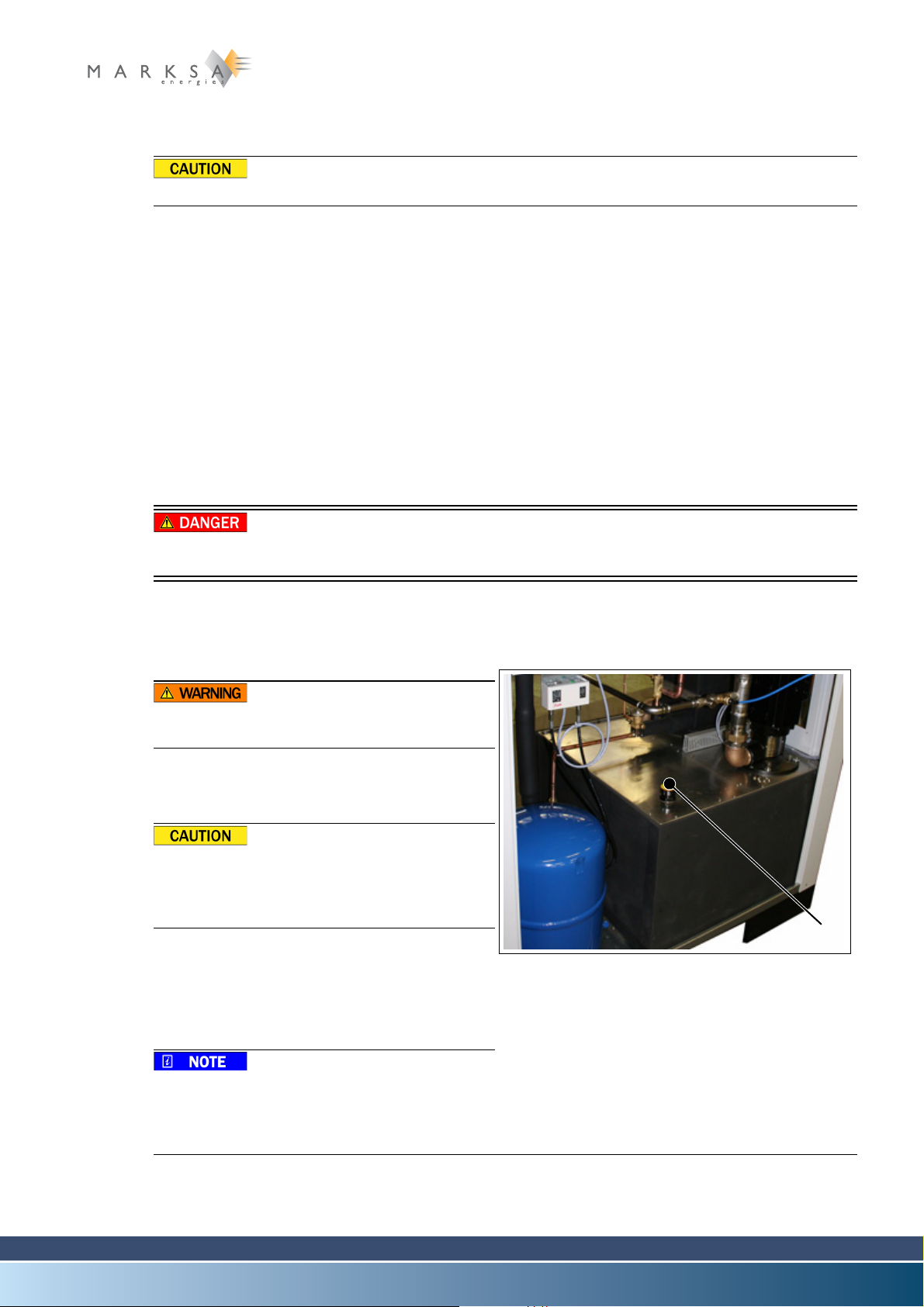
11.2 Handling
Fig. 11-3 : Filler cap
(1)
The unit must be transported flat and must not sustain any shocks.
11.3 Installation
The unit is normally installed close to the machine being cooled, as indicated on these installation plans.
During the installation, allow for a free space of about 0.5m around the refrigeration unit. This distance
must be 1m in front of the exhaust fan. With these precautions, both ventilation and maintenance access
will be made easier.
11.3.1 Hydraulic connections
Except where specifications state otherwise, the connections between the refrigeration unit and the machine being cooled can be made with pipes with a cross-section diameter at least equal to that indicated
in the technical characteristics.
See section “13.1.2 Technical specifications” on page 71.
11.3.2 Electrical connections
Model CSW 3000/3500/4700 11
ELECTROCUTION
The machine cabinet must be disconnected from power while connecting the cables.
Power cable .............................................installed with a 3m length (or according to customer specifica-
tions)
11.3.3 Filling the reservoir
The liquids used are not suitable for human
consumption.
A. Prepare a mixture of water and 30% ethylene gly-
col.
Do not use anti-freeze intended for motor vehicles.
Marksa recommends ANTIFROGEN N antifreeze.
B. Unscrew the cap (1).
C. Fill the reservoir to somewhere between the mini-
mum and maximum levels of the indicator (2).
D. Screw the cap back on.
A certain volume of the fluid is used to fill the
machine's circuit. Pay attention to the level
when starting up the machine and top up as
necessary.
Technical Notice V1.0 / 01.09 Page 73 / 100
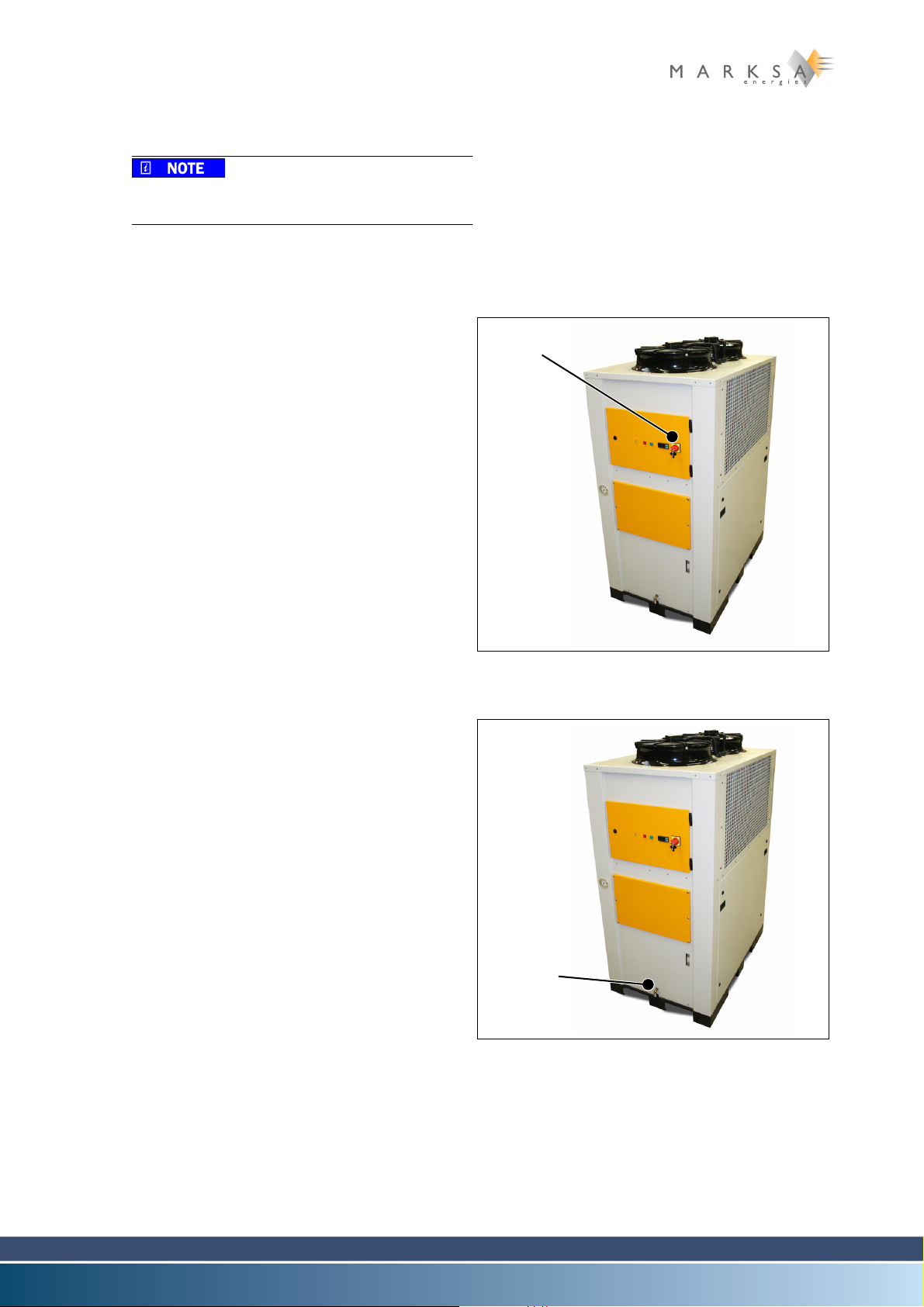
11 Model CSW 3000/3500/4700
Fig. 11-4 : Engaging
(1)
Fig. 11-5 : Emptying cap
(2)
11.4 Commissioning
The unit has been checked, tuned and tested in
our workshops.
A. Make the hydraulic and electrical connections.
B. Fill the reservoir with liquid.
C. Start up the machine (1).
D. Check the rotation direction of the pump and the
exhaust fan.
11.5 Specific tuning
11.5.1 Draining the reservoir
A. Put a container under the tap (2) or the drainage
plug located under the chiller.
B. Open the drainage tap.
11.6 Close the drainage tap once the reservoir is empty.
Page 74 / 100 Technical Notice V1.0 / 01.09
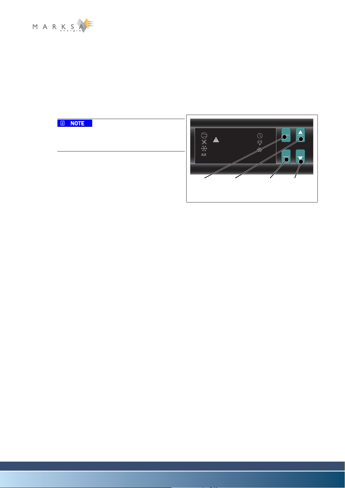
Chapter contents
Fig. 11-1 : Boutons du thermostat
888
Prg
mute out
Set def
(1) (2) (3) (4)
This chapter describes the various possible control settings and the common maintenance operations
for the entire range of CSW chillers.
11.1 Control settings
11.1.1 Thermostat
For machines equipped with the hot gas bypass option, the thermostat operation is different.
See section “12.7 Hot gas bypass (G)” on
page 79.
11.1.1.1 Description of the buttons
(1) PRG/mute button
Stop the thermostat alarm
(2) UP / out button
Increase the displayed setting's value
Return to the previous parameter
(3) SET Button
Save the setting's value
Display the value of the selected parameter
(4) DOWN / def button
Decrease the displayed setting's value
Go to the following parameter
Tuning and maintenance 11
11.1.1.2 Indications on the display
COMP .....................1 Led indicates that the com-
pressor is in operation.
Operation .............. The value displayed corres-
ponds to the value read by
the temperature probe.
11.1.1.3 Changing the setting
A. Hold down the SEL button for 1 second.
Its value is displayed.
The selected value flashes after a few moments
B. Increase or decrease the setting's value using the UP and DOWN buttons.
C. Press on SEL to confirm your choice.
11.1.1.4 Stopping the alarm
A. Press on PRG.
The alarm code remains in memory until the alarm is stopped.
11.1.1.5 High temperature alarm
The threshold setting is only assigned in the factory.
Technical Notice V1.0 / 01.09 Page 69 / 100
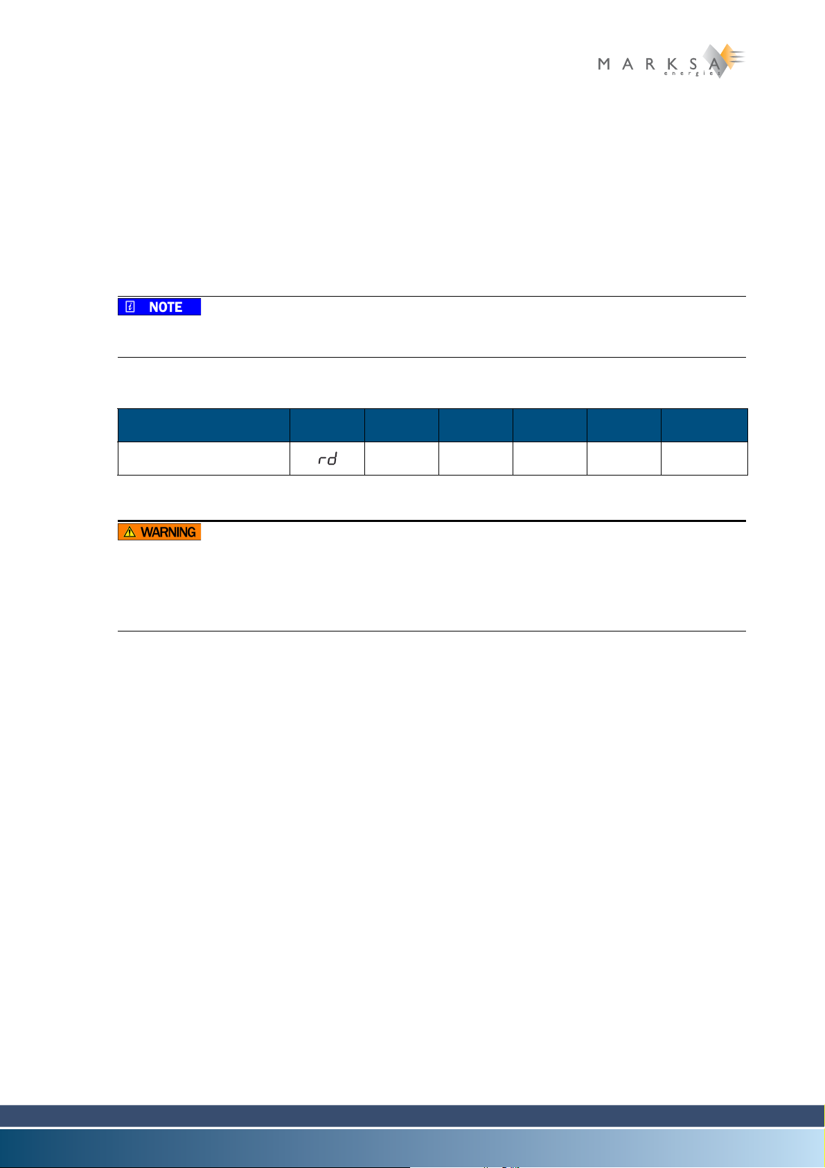
11 Tuning and maintenance
11.1.1.6 Modification of the configured parameters
A. Press on the PRG button for more than 5 seconds.
The first modifiable parameter is shown on the display.
B. Press on the UP and DOWN keys to specify the parameter that should be changed.
C. Press on SEL to display the value of the selected parameter.
D. Modify the value with the UP/DOWN keys until the desired value is displayed.
E. Press on the SEL button again to store the new value and move on to display the following parameter.
F. Press on the PRG key to store the new value and terminate the parameter modification procedures.
In order to exit without saving the values: just wait 60 seconds without doing anything to the machine.
Parameter Symbol Type Min. Max. Units Regulated
Differential regulator F 0.1 +19.9 °C / °F 2
Table 11-1: Control setting parameters
The only parameter that the user is authorised to change is the differential regulator. The modification of any other parameter may affect the operation of the refrigeration unit in an inappropriate manner.
Marksa SA denies all responsibility for any un-authorised parameter modification.
Page 70 / 100 Technical Notice V1.0 / 01.09
11.2 Maintenance
11.2.1 Periodic maintenance
Regular maintenance by competent personnel makes it possible to ensure reliable and efficient operation of the refrigeration unit.
11.2.2 Safety
ELECTROCUTION ET BLESSURES GRAVES
Always disconnect the power supply of the unit before any maintenance operation.
There is a significant risk of burns from contact with the copper piping.
11.2.3 Maintenance table
Interval Weekly Monthly Annually
Tuning and maintenance 11
Liquid level
Check for fouling of the air condenser X
Check the bearing clearances of the
exhaust fan motor
Clean the exhaust fan blades X
Check the refrigerating and hydraulic
circuits
Table 11-2: Maintenance table
X
11.2.4 Weekly maintenance
A. Check that the liquid is at the maximum level of the visual indicator.
An electrical level detector can be installed as an option.
B. Restart the unit by switching it off and back on again.
11.2.5 Monthly maintenance
A. Check for fouling of the air condenser
B. If necessary, blow compressed air through the exhaust fan from the outlet port of the exhaust fan.
C. Restart the unit by switching it back on.
X
X
Technical Notice V1.0 / 01.09 Page 71 / 100

11 Tuning and maintenance
11.2.6 Annual maintenance
Cut the power supply on the outside of the machine.
A. Check the exhaust fan motor bearings.
B. If need be, replace the bearings.
C. Clean the exhaust fan blades.
Start with a visual inspection of all of the components (cabling and capillaries included) in order to be
sure that noen of the components are either broken, damaged, ice-encrusted or fouled (exhaust fan,
condenser).
Due to a lack of gas, or operation of the unit at an evaporation temperature which is too low, the
heat exchangers can become ice-encrusted. When this happens, the time to "defrost" the unit
may take several hours.
D. Inside the unit, visually check the connections and pipes in the refrigeration circuit.
Traces of oil may indicate a gas leak.
E. Visually check all the connections and pipes in the hydraulic circuit.
Traces of water may indicate a loss of waterproofness.
F. Restart the unit by switching it back on.
Page 72 / 100 Technical Notice V1.0 / 01.09

Chapter contents
This chapter describes the various options and their availability depending on the refrigeration unit models.
12.1 List of the options
Legend:
O Option X Standard
Options 12
CSW
900 1000 -
1300 -
Abb. Option
CSW
50-65
& 80
CSW
100
& 150
CSW
200
& 300
CSW
400
CSW
600 &
800
1700
A Air filter X X X X
J By-pass O O O O O O O O
DDistributor
E 400 V power
supply
F Water-flow con-
troller
G Hot gas bypass O O O O O O O O
H Pre-heating kit
I Thermal insula-
tion
L Differential ther-
mostat
M Frame on cast-
ers
O O O O O O O O
O X X X X X
O O O O O O O O
O O O O O O
O O O O O O O O
O O O O O O O O
O O O O O
CSW
2000
&
2400
CSW
3000 -
3500
&
4700
N Water-level con-
trol
P Pressurised
hydraulic sys-
tem
R Reinforced
pump
S LP/HP safety
pressure con-
trollers
T Timer (program-
ming clock)
Table 12-1: List of the options
O O X X X X X X
O O
O O O O O O O
O O X X X X X X
O O O O O O
Technical Notice V1.0 / 01.09 Page 73 / 100

12 Options
CSW
Abb. Option
50-65
& 80
W Electric valve
and
solenoid
Y
Programma-
ble problem
recovery
controller
Z High tempera-
ture alarm
Table 12-1: List of the options
CSW
CSW
100
& 150
CSW
200
& 300
CSW
400
CSW
600 &
800
900 1000 -
1300 -
1700
O O O O O O
O O O O X X
O O O O O O O O
CSW
2000
&
2400
CSW
3000 -
3500
4700
&
Page 74 / 100 Technical Notice V1.0 / 01.09

12.2 Air filter (A)
(1)
12.2.1 Description of the option
Options 12
Fig. 12-1 : Air filter (metallic)
Air filters make it possible to protect the condenser against impurities in the air.
The filters can be either metallic or synthetic.
12.2.2 Maintenance
12.2.2.1 Metallic filters
Metallic filters should be cleaned monthly during the regular monthly maintenance procedure.
12.2.2.2 Synthetic filters
Synthetic filters should be replaced monthly during the regular monthly maintenance procedure.
12.2.3 Breakdowns
No special breakdown procedures
Technical Notice V1.0 / 01.09 Page 75 / 100

12 Options
TH
BP - HP
(1)
12.3 By-pass (J)
12.3.1 Description of the option
Fig. 12-2 : Basic schematic
In the event of excessive pressure in the outlet port of the refrigeration unit, the bypass is engaged and
reinjects the liquid into the reservoir in order to avoid damages in the external circuit.
12.3.2 Maintenance
The bypass is regulated in the factory. No maintenance or adjustment by the customer is authorised.
12.3.3 Breakdowns
No special breakdown procedures.
Page 76 / 100 Technical Notice V1.0 / 01.09

12.4 Distributor (D)
12.4.1 Description of the option
The distributor makes it possible to split the refrigeration liquid between several circuits.
12.4.2 Maintenance
No special maintenance procedures.
12.4.3 Breakdowns
No special breakdown procedures.
12.5 400V power supply (E)
12.5.1 Description of the option
A 400V power supply makes it possible to use electrical components with very high reliability.
12.5.2 Maintenance
No special maintenance procedures.
12.5.3 Breakdowns
Options 12
No special breakdown procedures.
Technical Notice V1.0 / 01.09 Page 77 / 100

12 Options
TH
T
(1)
12.6 Water-flow controller (F)
12.6.1 Description of the option
Fig. 12-3 : Basic schematic
The water flow controller makes it possible to detect faults in the external refrigeration circuit (the customer's machine). Its operation is to provide a delay in order to avoid the display of disruptive errors during
the start-up of the refrigeration unit.
12.6.2 Maintenance
No special maintenance procedures.
12.6.3 Breakdowns
"Faulty flow" message on the programmable controller display
- Cooling circuit is obstructed
✔ Check the hydraulic system
Check the level of water in the reservoir
The dimensions of the connecting pipes
The rotation direction of the pump
Page 78 / 100 Technical Notice V1.0 / 01.09

12.7 Hot gas bypass (G)
TH
BP - HP
(1)
12.7.1 Description of the option
Options 12
Fig. 12-4 : Basic schematic
The hot gas bypass option makes it possible to precisely maintain the liquid temperature by eliminating
disruptive starting up and powering down of the compressor.
Precision in the order of ± 0.1°C is possible with the addition of an Omron thermostat.
Technical Notice V1.0 / 01.09 Page 79 / 100
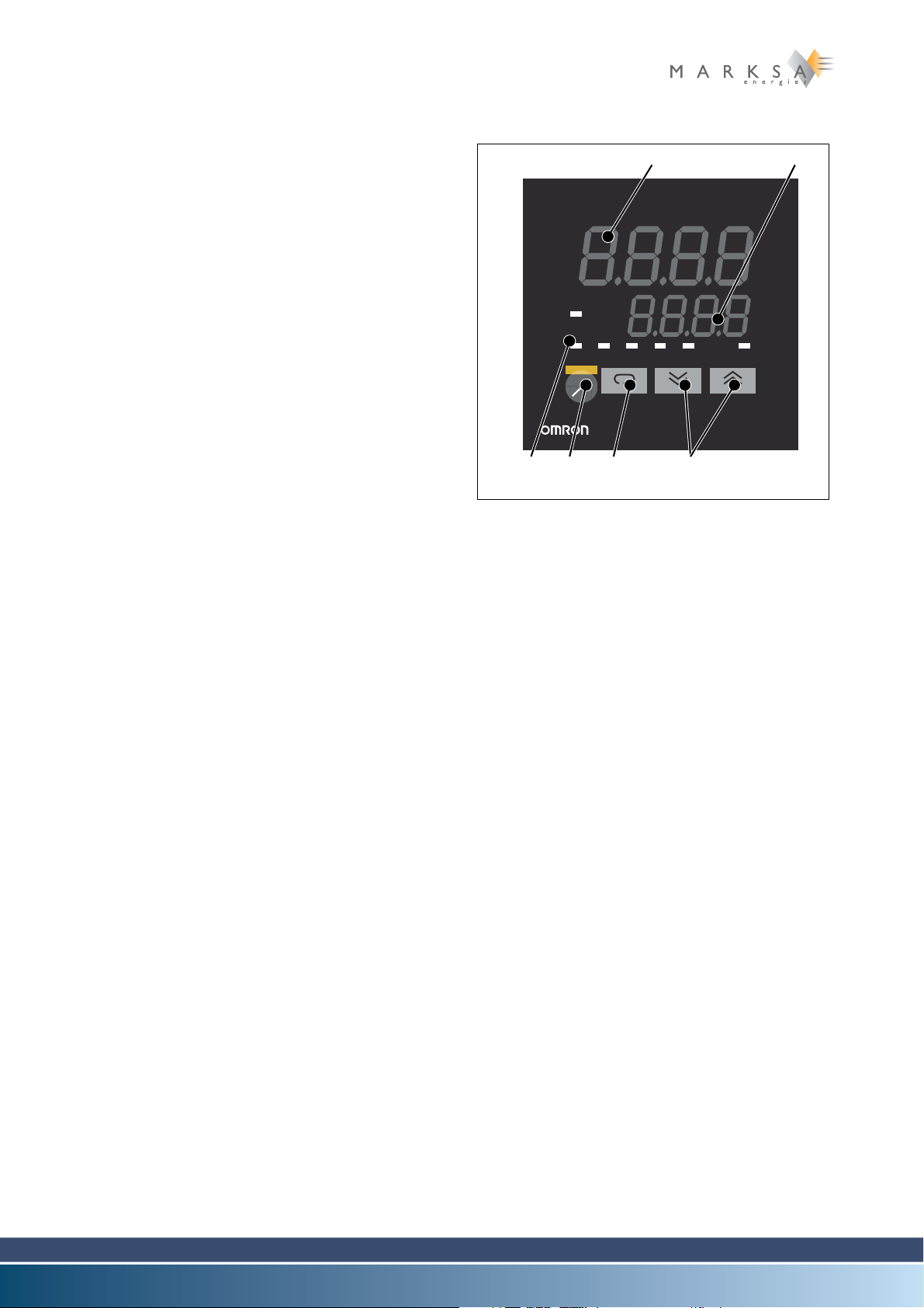
12 Options
Fig. 12-5 : Affichage du thermostat
OUT2 MANU STOP RMT AT SUB1
OUT1
PV
sv
E5CK
A
M
(1) (2)
(3) (4) (5) (6)
12.7.2 Thermostat
12.7.2.1 Description
(1) Display n°. 1
Displays the process value or the parameter symbols.
(2) Display n°. 2
Displays the setting's value, the ramp setting's value, the heating capacity or the selection of parameters.
(3) Visual operation indicators
-OUT1
Alight: Operation of outlet 1 switches to ON
-OUT2
Alight: Operation of outlet 2 switches to ON
-SUB1
Alight: Operation of the auxiliary outlet switches to ON
-MANU
Alight: Manual mode is activated
-STOP
Alight: The device is stopped
- RMT (remote)
Alight: Remote control is activated
- AT (auto-tuning)
Flashes during automatic regulation of the
(4) A/M key
(5) Display key
(6) Increment / decrement keys
PID
Selection between manual / automatic mode
- Pressing < 1 sec
Move to the next parameter
- Pressing > 1 sec
Display of the menu
Increases or decreases the value in display window n°2
12.7.2.2 Parameters
Level 1
AL-1 Alarm 1 value............................ 5
AL-2 Alarm 2 value............................ 5
P Proportional band ..................... 0.4
I Integration time......................... 134
D Derivation time.......................... 20
Niveau 2
ALH1 Al 1 Hysteresis.......................... 0.1
Page 80 / 100 Technical Notice V1.0 / 01.09
ALH2 Al 2 Hysteresis.......................... 0.1
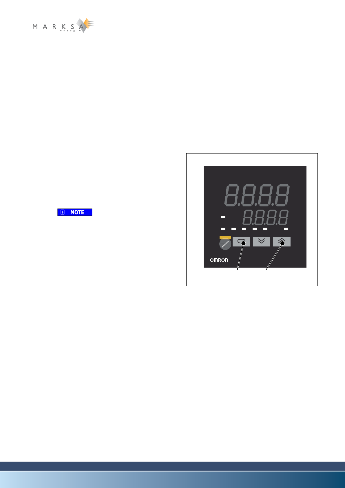
Parameter setting mode (SET)
Fig. 12-6 : Thermostat display
OUT2 MANU STOP RMT AT SUB1
OUT1
PV
sv
E5CK
A
M
(1) (2)
Ent-t Entry type ..................................1
d-U Select either °C / °F ...................C
oUt 1 Cont allocation 1........................Heat
oUt 2 Cont allocation 2........................Al 1
Sub 1 Auxiliary outlet ...........................Al 2
AL t 1 Alarm 1 type ..............................2
AL In Alarm 1 opening ........................n-C
AL t 2 Alarm 2 type ..............................2
AL 2 n Alarm 2 opening ........................n - C
or Eu Normal / inv. operation ..............o r - r
12.7.2.3 Activation of auto-tuning
A. Hold down the button (1) for more than one se-
cond.
B. Press once on (2).
C. Hold down the button (1) for more than one se-
cond to go to level 1.
D. Press on (2) to activate auto-tuning.
Options 12
This operation may take several dozens of minutes.
This operation will modify the P.I.D. values to
optimise the operation of the device.
12.7.3 Maintenance
No special maintenance procedures.
12.7.4 Breakdowns
No special breakdown procedures.
Technical Notice V1.0 / 01.09 Page 81 / 100

12 Options
TH
BP - HP
(1) (2)
12.8 Pre-heating kit (H)
12.8.1 Description of the option
Fig. 12-7 : Schéma de principe
Heating (1) makes it possible to pre-heat water that might be too cold, particularly useful when pre-heating the machine or when the refrigeration unit(s) are located outside the building.
A safety thermostat (2) protects the tank from inadequacies in the heating system.
12.8.2 Maintenance
No special maintenance procedures.
12.8.3 Breakdowns
No special breakdown procedures.
Page 82 / 100 Technical Notice V1.0 / 01.09

12.9 Thermal insulation (I)
12.9.1 Description of the option
Thermal insulation of the refrigeration unit makes it possible to reduce condensation. This option is recommended particularly for situations where the refrigeration units supply water at a temperature less
than 15°C (59°F).
12.9.2 Maintenance
No special maintenance procedures.
12.9.3 Breakdowns
No special breakdown procedures.
12.10 Differential thermostat (L)
12.10.1 Description of the option
In non air-conditioned environments, the differential thermostat makes it possible to automatically adjust
the refrigerant liquid temperature.
Options 12
12.10.2 Maintenance
No special maintenance procedures.
12.10.3 Breakdowns
No special breakdown procedures.
12.11 Chassis sur roulettes (M)
12.11.1 Description of the option
Casters fixed to the refrigeration unit make it easier to relocate the unit.
12.11.2 Maintenance
No special maintenance procedures.
12.11.3 Breakdowns
No special breakdown procedures.
Technical Notice V1.0 / 01.09 Page 83 / 100

12 Options
TH
T
(1)
12.12 Contrôle de niveau (N)
12.12.1 Description of the option
Fig. 12-8 : Basic schematic
A float in the reservoir makes it possible to check on the liquid levels. If the level is too low, in order to
avoid any damage, the refrigeration unit stops itself and an alarm is shown on the programmable controller display and/or on the visual display located on the front panel.
It is recommended to fill the tank up to the visual display level.
12.12.2 Maintenance
No special maintenance procedures.
12.12.3 Breakdowns
The float no longer indicates the actual water level (float is blocked)
- Non-standard antifreeze product or no anti-freeze
✔ Drain the reservoir
Clean the level
Put in compliant refrigerant liquid
Page 84 / 100 Technical Notice V1.0 / 01.09
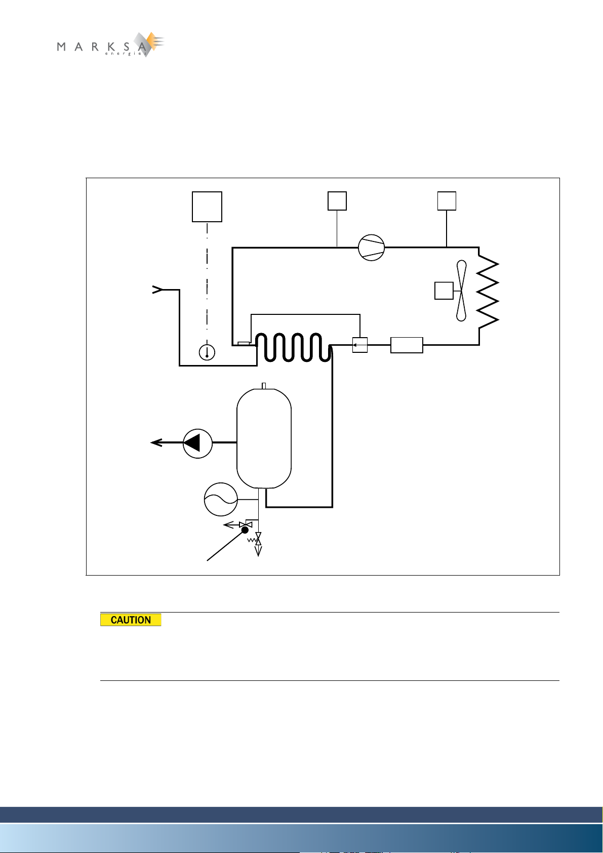
12.13 Circuit d’eau sous pression (P)
HP
BP
TH
(1)
12.13.1 Description of the option
The customer's circuit is pressurised (several bars).
12.13.2 Maintenance
Maintenance and required checking are reduced.
Options 12
Fig. 12-9 : Basic schematic
The circuit is pressurised. Eliminate the pressure before any intervention on the customer's cooling circuit:
Open the drainage tap (1) and check the manometer until zero pressure is obtained.
12.13.3 Breakdowns
Consult a specialist for any intervention.
Technical Notice V1.0 / 01.09 Page 85 / 100

12 Options
12.14 Reinforced pump (R)
12.14.1 Description of the option
A reinforced pump makes it possible to ensure better liquid circulation during significant load losses (cooling of spindles, for example).
12.14.2 Maintenance
No special maintenance procedures.
12.14.3 Breakdowns
No special breakdown procedures.
Page 86 / 100 Technical Notice V1.0 / 01.09

12.15 LP/HP safety pressure controllers (S)
TH
T
BP - HP
(1)
12.15.1 Description of the option
Options 12
Fig. 12-10 : Basic schematic
The pressure controller (1) makes it possible to protect the compressor against any possible loss of gas
in the refrigeration circuit (LP) and protects the compressor after any significantly excess of pressure of
the refrigerant gas (HP).
12.15.2 Maintenance
No special maintenance procedures.
Technical Notice V1.0 / 01.09 Page 87 / 100

12 Options
12.15.3 Breakdowns
Activation of the LP section
- Gas leakage, insufficient gas quantities
✔ Find the origin of the leakage(s).
Activation of the HP section
- Fouled heat exchanger
✔ Clean the heat exchanger and air filters (if fitted).
- Ambient temperature is too high (above the manufacturer's specified limit).
- - Insufficient free space around the unit.
- - Faulty exhaust fan.
12.16 Timer (T)
Check and reconnect the circuit.
12.16.1 Description of the option
The timer (programmable clock) makes it possible to stop the unit outside of its normal operating hours
and restart it if necessary.
12.16.2 Maintenance
No special maintenance procedures.
12.16.3 Breakdowns
No special breakdown procedures.
12.17 Electric valve and solenoid (W)
12.17.1 Description of the option
The valve controlled by the solenoid makes it possible to avoid the reservoir overflowing when the machine stops. It is necessary when the unit is located at a height below that of the machinery being cooled.
12.17.2 Maintenance
No special maintenance procedures.
12.17.3 Breakdowns
- Reservoir overflow
✔ Check the solenoid and valve.
Page 88 / 100 Technical Notice V1.0 / 01.09

12.18 High temperature alarm (Y)
12.18.1 Description of the option
The high temperature alarm indicates an incorrect operation of the device. This information is forwarded
to the device by the equipment being cooled.
An error is forwarded to the device in the event of overheating. It may be caused by:
- A loss of gas.
- A loss of power capacity.
12.18.2 Maintenance
No special maintenance procedures.
12.18.3 Breakdowns
No special breakdown procedures.
Options 12
Technical Notice V1.0 / 01.09 Page 89 / 100

12 Options
Page 90 / 100 Technical Notice V1.0 / 01.09
Chapter contents
This chapter contains instructions useful in the event of a breakdown of your refrigeration unit.
13.1 Warnings
We decline all responsibility for operations carried out on the unit by non-qualified personnel.
Before intending to repair the refrigeration circuit strictly speaking, first ensure that control system is working properly and is correctly configured.
If, even after checking and confirming the control settings of the temperature regulation system, the
breakdown persists, then it is necessary to check and possibly to repair the refrigeration unit.
Changing the settings of and making repairs to the refrigerated circuit are very delicate operations. With
this motive in mind, we do advise you to entrust such work to a qualified refrigeration engineer.
13.2 Checks
13.2.1 Pressure checks
It is highly recommended to entrust any intervention to a specialist refrigeration engineer.
Breakdowns 13
BEFORE ANY INTERVENTION ON THE UNIT, CUT OFF ITS POWER SUPPLY AT THE SOURCE.
B
E CAREFUL WITH CERTAIN PARTS OF THE REFRIGERATED CIRCUIT WHICH CAN GET VERY HOT (IN PARTICULAR
THE BRASS PIPINGS).
At present, HFC gases represent the best solution as regards the protection of the environment.
However, they must be handled with care and must be never released into the atmosphere, but
recovered back into a reservoir.
For this control, two manometers exclusively reserved for the use of HFC gases are necessary:
• 1 low-pressure (LP) manometer graduated from 1 to 10 bars.
• 1 high-pressure (HP) manometer graduated from 0 to +30 bars.
Each of these manometers needs to be equipped with a flexible pipe terminated with a 1/4 " flare coupling.
Technical Notice V1.0 / 01.09 Page 91 / 100

13 Breakdowns
Fig. 13-1 : programmable problem recovery
controller
(1)
13.3 Breakdowns
Before any intervention on the unit, cut off its power supply at the source. Take care of certain
parts of the refrigeration circuit which can be very hot.
Problems with normal operations are manifested by:
• a halt of the refrigeration unit (one or more pumps and/or the compressor do not run)
• abnormal discrepancies in the coolant temperature.
At the first occurrence of an abnormal situation, the cause of the problem should be determined following
the procedures listed below.
If Option Y, programmable problem recovery
controller is installed:
- Consult the display unit (1).
13.3.1 The unit doesn't work
Looking for the cause of the breakdown:
A. Check the power supply for the unit.
B. Check that the safety switch (10Q1) is in position 1 (power on for the unit),
C. Check the pump circuit breaker if there is one (check the schematics in the technical data sheet). Acces-
sible by opening the unit's cover hood.
D. Check the power supply for the command circuit (fuse).
E. Check the level of the liquid in the reservoir: If the level is too low, the pump stops and signals a fault.
After topping up the liquid, the unit must be stopped and restarted by toggling the safety switch (10Q1)
in order to suppress the fault signal.
F. Check if the pump is running. The motor might be controlled with the electric contact switch (option). A
switch (optional) protects the pump in the event of overload.
Page 92 / 100 Technical Notice V1.0 / 01.09

Breakdowns 13
The motor doesn't run
- Check the rotation direction.
- Circuit breaker activated
✔ Check the liquid level.
✔ Reset the circuit breaker.
- Faulty bearings
✔ Replace the bearings.
- Insufficient fluid
✔ Add some fluid.
- Non-standard fluid quality
✔ Change the fluid.
- Motor out of order
✔ Replace the motor.
The motor runs, but without the pressure increasing in the circuit concerned
- Faulty pump
✔ Replace the pump
G. Check that the compressor is running
The compressor is powered on but doesn't work
- The internal compressor safety switch has been activated
✔ Cut off the power supply
Let the unit cool off (may take several hours)
Restart the unit
✔ Check that the exhaust fan is working properly
Clean the condenser
LP contact is open (optional on CSW50 through CSW150), intake pressure too low
for the compressor
- Gas leakage?
✔ Call a refrigeration engineer to repair the leak and refill the circuit with gas
LP contact is open (optional), intake pressure too low for the compressor
- The breakdown is indicated on the breakdown indicator (starting at model CSW200)
✔ Follow the instructions
Technical Notice V1.0 / 01.09 Page 93 / 100

13 Breakdowns
Fig. 13-2 : Pressostat
(1)
HP contact is open (optional on CSW50 through CSW150)
- Ambient temperature is too high
✔ Cut off the power supply
- Filters (optional) fouled
✔ Clean or replace the filters
✔ Faulty exhaust fan Clean the
- Condenser fouled
✔ Clean the condenser.
Cool down the local environment
Restart the unit by pressing the
pressure switch RESET button
(1)
Restart the power supply
exhaust fan or replace it.
The thermostat no longer controls the
compressor
- Faulty probe (the alarm message Er... on the thermostat display)
✔ Replace the probe
- Faulty thermostat
✔ Replace the thermostat
The unit will not restart after a RESET (if option Y programmable problem recovery
controller is not installed)
- Problem in the LP section
✔ Call a refrigeration engineer
- If the refrigeration unit won't perform after a careful check following our procedures,
please call a local refrigeration engineer.
Page 94 / 100 Technical Notice V1.0 / 01.09

Chapter contents
LEISTUNGSAUFNAHME
This chapter contains various information applicable to the entire range of CSW water chillers. For information specific to your model, please refer to the schematics and technical data sheets in the appendix.
14.1 Compliance
14.1.1 Directives
Your refrigeration unit is compliant with directive 98/37/CE from the European Parliament and Council
on June 22nd 1998 relating to the unification of the legislation of member states regarding machinery.
For further details, please refer to the compliance declaration included in the technical data sheet.
14.1.2 Identification plate
An identification plate is attached to the refrigeration unit. It contains the primary data specifications of
the unit in terms of manufacturing date, serial number, refrigerant gas, volume and capacity.
Appendix 14
Fig. 14-1 : Identification plate
Technical Notice V1.0 / 01.09 Page 95 / 100

Appendix
14.2 Disposal of the product
14.2.1 General remarks
In order to protect both people and the environment, any device and its accessories must be disposed
of according to regulations. The legislation and local regulations applicable for the elimination of waste
must also necessarily be respected.
A device may only be dismantled by a qualified technician.
Parts and sub-assemblies removed by the technician cannot be reused, except when their envisaged
use has been approved in writing by the manufacturer. Any future application of such parts must be precisely detailed in the request.
14.2.2 Preparation
A. Completely drain the hydraulic circuit into an clearly identified empty container.
B. As regards the refrigeration gases, you must use a company authorised for such activities.
C. Extract the gas, store it in resistant pressure vessel bearing the inscription "RECYCLING" and request
the name of a refrigerant fluid recycler.
D. In Switzerland, if the volume of gas is over 3kg, the operation must be declared to the cantonal authori-
ties.
E. When the device is empty of gas, recover the compressor oil in an appropriately identified waterproof
container.
F. The other components of the unit might also be recyclable:
• copper or stainless steel from the exchanger,
• sheet metal,
• copper electrical cables.
Page 96 / 100 Technical Notice V1.0 / 01.09
14.3 Maintenance sheet
The original blank maintenance sheet must be kept with this manual. Whenever a maintenance
intervention is required, make a copy of it and then fill out the details.
Maintenance / Event / Fault Action Operator Date
Appendix 14
100
Technical Notice V1.0 / 01.09 Page 97 / 100

Appendix
14.4 Technical data sheet
This notice being common to several refrigeration unit models, the information specific to your model appears in a separately delivered technical data file. This file contains the following elements:
• Electrical schematics
• Test sheets
• List of accessory parts
Page 98 / 100 Technical Notice V1.0 / 01.09

14.5 Compliance documents
Appendix 14
100
Technical Notice V1.0 / 01.09 Page 99 / 100
Le Locle, le 11 juin 1998 Joël L'HER Directeur
DECLARATION DE CONFORMITE
Nous, MARKSA S.A. – av. du Technicum 42 – 2400 Le Locle, déclarons sous notre seule responsabilité que la
machine :
Marque : Marksa
Type : CSW-CPW-CPO-CPOW
No. de série : 100 / 150 / 200 / 300 /400 / 600 / 700 / 800 / 900 / 1000 / 1300 / 1700 / 2000 / 2400 /
3500 /4700
Décrite dans la documentation jointe est conforme à la directive machines 89/392 avec les amendements 91/368 et
93/44, à la directive 73/23 ainsi qu'à la directive CEM/EMV 89/336 avec les amendements 92/31.
Nous déclarons que la présente machine est conforme.
DECLARATION OF CONFORMITY
We, MARKSA S.A. – av. du Technicum 42 – 2400 Le Locle, declare under our sole responsibility that the machine :
Fabrication : Marksa
Type : CSW-CPW-CPO-CPOW
Serial number : 100 / 150 / 200 / 300 /400 / 600 / 700 / 800 / 900 / 1000 / 1300 / 1700 / 2000 / 2400 /
3500 /4700
describes in the enclosed engineering data are in conformity with machine's directive 89/392 with amendments
91/368 and 93/44, with directive 73/23 and with directive CEM/EMV 89/336 with amendments 92/31.
We declare that this machine are in conformity.
KONFORMITÄTSERKLÄRUNG
Wir, MARKSA S.A. – av. du Technicum 42 – 2400 Le Locle, erklären in alleiniger
Verantwortung, dass die Maschine :
Handelsmarke : Marksa
Typ : CSW-CPW-CPO-CPOW
Serienummer : 100 / 150 / 200 / 300 /400 / 600 / 700 / 800 / 900 / 1000 / 1300 / 1700 / 2000 / 2400 /
3500 /4700
beschreibt bei angefügte Unterlagen ist konform mit Maschinenanweisungen 89/392 mit die Abänderüngen 91/368
und 93/44, laut Anweisung 73/23 und laut Anweisung CEM/EMV 89/336 mit Abänderüngen 92/31 ist.
Wir erklären, dass diese Maschine ist in Konformität
.
DICHIARAZIONE DI CONFORMITÀ
Noi, MARKSA S.A. – av. du Technicum 42 – 2400 Le Locle, dichiariamo sotto la nostra
esclusiva responsabilità che la macchina :
Marca : Marksa
Typo : CSW-CPW-CPO-CPOW
Numéro di série : 100 / 150 / 200 / 300 /400 / 600 / 700 / 800 / 900 / 1000 / 1300 / 1700 / 2000 / 2400 /
3500 /4700
descritta nella documentazione è conforme con le direttive macchine 89/392 con gli ammendamenti 91/368 e
93/44, con direttive 73/23 e con direttive CEM/EMV 89/336 con gli ammendamenti 92/31.
Noi dichiariamo che la macchina è conforme.
 Loading...