

Page 1
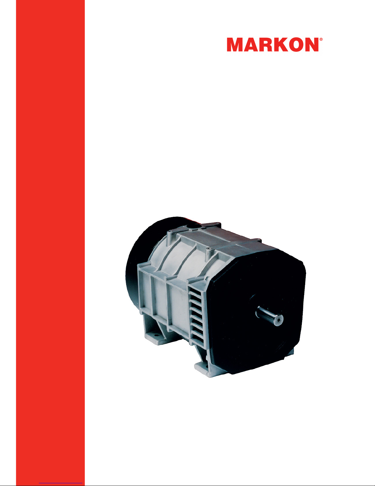
BL105 and SL105 Alternators
INSTALLATION, SERVICE AND
MAINTENANCE
English
A046V047 (Issue 1)
Original Instructions
Page 2

Page 3

Table of Contents
1. FOREWORD ......................................................................................................................... 1
2. SAFETY PRECAUTIONS...................................................................................................... 3
3. SAFETY DIRECTIVES AND STANDARDS .......................................................................... 7
4. INTRODUCTION ................................................................................................................. 11
5. APPLICATION OF THE ALTERNATOR ............................................................................. 13
6. INSTALLATION INTO THE GENERATOR SET ................................................................. 17
7. SERVICE AND MAINTENANCE......................................................................................... 21
8. FAULT FINDING ................................................................................................................. 29
9. PARTS IDENTIFICATION ................................................................................................... 33
10. SERVICE PARTS AND AFTER SALES SERVICE............................................................. 39
11. END OF LIFE DISPOSAL ................................................................................................... 41
A046V047 (Issue 1) i
Page 4

-
This page is intentionally blank.
ii A046V047 (Issue 1)
Page 5

1 Foreword
1.1 The Manual
This manual contains guidance and instructions for the installation, servicing and
maintenance of the alternator.
Before operating the alternator, read this manual and make sure that all personnel who work
on the equipment have access to the manual and all additional documentation supplied with
it. Misuse and failure to follow the instructions, and the use of non-approved parts, may
invalidate the product warranty and lead to potential accidents.
This manual is an essential part of the alternator. Make sure that the manual is available to
all users throughout the life of the alternator.
The manual is written for skilled electrical and mechanical technicians and engineers, who
have prior knowledge and experience of generating equipment of this type. If in doubt,
please seek expert advice or contact your local Cummins Generator Technologies
subsidiary.
NOTICE
Information in this manual was correct when published. It may be superseded due to our
policy of continuous improvement. Please visit www.cumminsgeneratortechnologies.com for
latest documentation.
A046V047 (Issue 1) 1
Page 6

-
This page is intentionally blank.
2 A046V047 (Issue 1)
Page 7
2 Safety Precautions
2.1 Safety Information and Notices used in this
manual
Danger, Warning and Caution panels are used in this manual to describe the sources of
hazards, their consequences and how to avoid injury. Notice panels emphasize important or
critical instructions.
DANGER
Danger indicates a hazardous situation which, if not avoided, WILL result in death or serious
injury.
WARNING
Warning indicates a hazardous situation which, if not avoided, COULD result in death or
serious injury.
CAUTION
Caution indicates a hazardous situation which, if not avoided, COULD result in minor or
moderate injury.
NOTICE
Notice refers to a method or practice which can result in product damage, or to draw
attention to additional information or explanations.
2.2 Skill Requirements of Personnel
Service and maintenance procedures must only be carried out by experienced and qualified
engineers, who are familiar with the procedures and the equipment.
2.3 Risk Assessment
A risk assessment has been performed on this product by Cummins, however a separate
risk assessment must be performed by the user/operating company to establish all
personnel-related risks. All affected users must be trained on the identified risks. Access to
the Power Plant/Generator Set during operation must be restricted to persons who have
been trained on these risks.
2.4 Personal Protective Equipment (PPE)
All persons operating, servicing, maintaining or working in or with a power plant or a
generator set must wear appropriate Personal Protective Equipment (PPE)
A046V047 (Issue 1) 3
Page 8
-
Recommended PPE includes:
• Ear and Eye Protection
• Head and face protection
• Safety footwear
• Overalls that protect the lower arms and legs
Ensure that all persons are fully aware of the emergency procedures in case of accidents.
2.5 Noise
CAUTION
Alternators in operation emit noise. Exposure to noise can cause hearing damage. Wear
appropriate ear protection at all times. Maximum A-weighted noise emissions may reach 110
dB(A). Contact the supplier for application-specific details.
2.6 Electrical Equipment
DANGER
Hazardous Voltage
Will shock, burn or cause death
All electrical equipment can be dangerous if not operated correctly. Always install, service
and maintain the alternator in accordance with this manual.
Work that requires access to electrical conductors must comply with all applicable local and
national electrical safety procedures for the voltages involved and any site specific rules.
Always use genuine branded replacement parts.
2.7 Lock Out/Tag Out
WARNING
Risk of serious injury or death
Alternators can retain mechanical and electrical energy
Isolate the alternator from all sources of mechanical and electrical energy before starting
service or maintenance work. Adopt a suitable lock-out/tag out process.
2.8 Lifting
WARNING
Improper lifting can cause serious injuries to persons or can cause death.
Do not use the alternator lifting points to lift the complete generator set (alternator coupled to
motive power source)
The lifting points provided are designed for lifting the alternator only.
Do not remove the lifting label attached to one of the lifting points.
4 A046V047 (Issue 1)
Page 9
-
2.9 Alternator Operating Areas
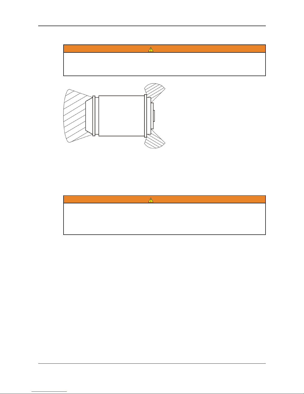
WARNING
Flying debris
In the event of catastrophic failure, debris may be ejected from the alternator air inlet/outlet
and may cause severe injury or death.
Avoid access to these areas while the alternator is operating.
Always wear suitable PPE when working in hatched areas or directly in-line with any air
inlet/outlet.
Make sure this consideration is captured in your risk assessment.
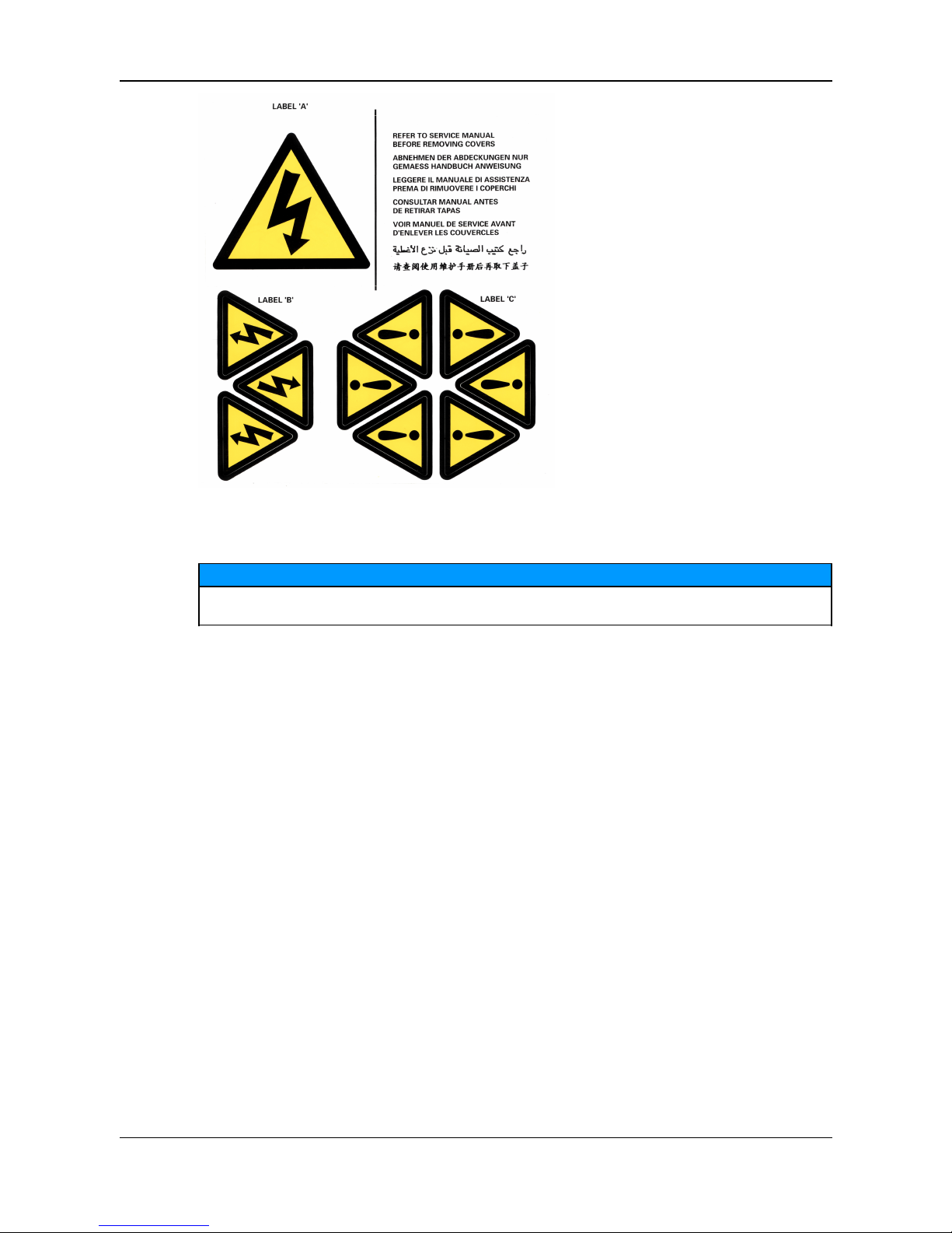
2.10 Hazard Warning Labels
WARNING
Hazard warning labels show the type and source of potential hazards. Observe the
safety labels to avoid risk of injury. The generator set manufacturer is responsible
for fitting the self-adhesive hazard warning labels supplied with the alternator.
Labels must be fitted at the locations shown on the back of the label sheet supplied
with the alternator manual.
Replace labels that are missing, damaged or painted over.
A046V047 (Issue 1) 5
Page 10
-
2.11 General Guidance
NOTICE
These safety precautions are for general guidance and supplement your own safety
procedures and all applicable laws and standards.
6 A046V047 (Issue 1)
Page 11

3 Safety Directives and Standards
MARKON Alternators meet applicable European safety directives, and national and
international standards relevant to alternators. The alternator must be operated within the
limits specified in the relevant standards and within the parameters on the alternator rating
plate.
Marine alternators meet the requirements of all the major marine classification societies.
A046V047 (Issue 1) 7
Page 12
-
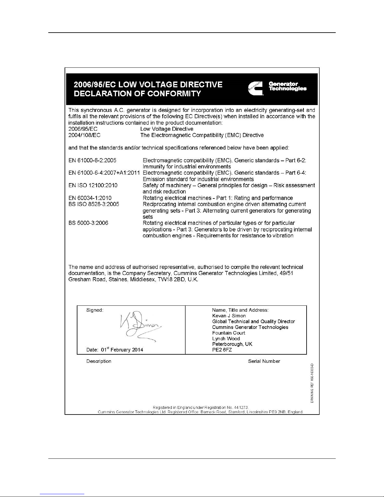
3.1 European Directives: EC Declaration of
Conformity for Incorporation
FIGURE 1. DECLARATION OF CONFORMITY
8 A046V047 (Issue 1)
Page 13
-
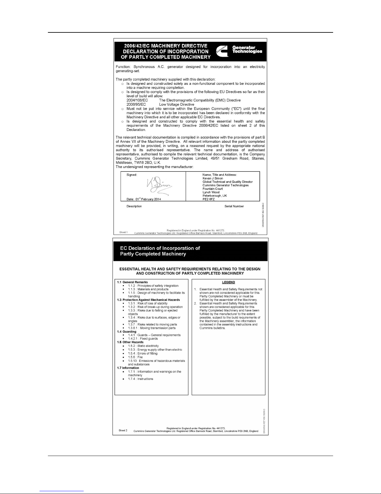
FIGURE 2. DECLARATION OF INCORPORATION
A046V047 (Issue 1) 9
Page 14

-
Each alternator supplied in the European Economic Area (EEA) is supplied with an EC
Declaration of Conformity or Declaration of Incorporation for incorporation into an electricity
generator set. It is the responsibility of the generator set manufacturer to ensure that the
complete generator set complies with EC Directives and standards.
Our authorized representative in the European Community is the Company Secretary,
Cummins Generator Technologies Limited, 49/51 Gresham Road, Staines, Middlesex, TW18
2BD, UK.
All alternators meet the following Standards and Directives insofar as their level of build will
allow:
Directives:
• 2004/108/EC The Electromagnetic Compatibility (EMC) Directive (see specific
Declarations)
• 2006/95/EC Low Voltage Directive (for product below 1000 V
a.c.
- see specific
Declarations)
• 2006/42/EC Machinery Directive (as partly completed machinery - see specific
Declarations)
Standards:
• EN 61000-6-2:2005 Electromagnetic Compatibility (EMC), Generic Standards - Part 62: Immunity for industrial environments
• EN 61000-6-4:2007 + A1:2011 Electromagnetic Compatibility (EMC), Generic
Standards - Emission standard for industrial environments
• EN ISO 12100:2010 Safety of Machinery, General principles for design - Risk
assessment and risk reduction
• EN 60034-1:2010 Rotating electrical machines - Part 1: Rating and performance
• BS ISO 8528-3:2005 Reciprocating internal combustion engine driven alternating
current generating sets - Part 3: Alternating current generators for generating sets
• BS 5000-3:2006 Rotating electrical machines of particular types or for particular
applications - Part 3: Generators to be driven by reciprocating internal combustion
engines - Requirements for resistance to vibration
3.2 Additional Information for EMC Compliance
MARKON alternators are designed to meet EMC emissions and immunity standards for
industrial environments. Additional equipment may be required when the alternator is
installed in residential, commercial and light industrial environments.
The installation ‘earth/ground’ arrangements require the connection of the alternator frame to
the site protective earth conductor using a minimum lead length.
Installation, maintenance and servicing must be carried out by adequately trained personnel
fully aware of the requirements of the relevant EC directives.
NOTICE
Cummins Generator Technologies is not liable for EMC compliance if unauthorized parts, not
of MARKON brand, are used for maintenance and servicing.
10 A046V047 (Issue 1)
Page 15
4 Introduction
4.1 Models
The models covered by this manual are designated in the following ranges:
• BL105A, BL105B, BL105C, BL105E, BL105F and BL105G
• SL105A, SL105B, SL105C, SL105E, SL105F and SL105G
4.2 BL105 Alternator
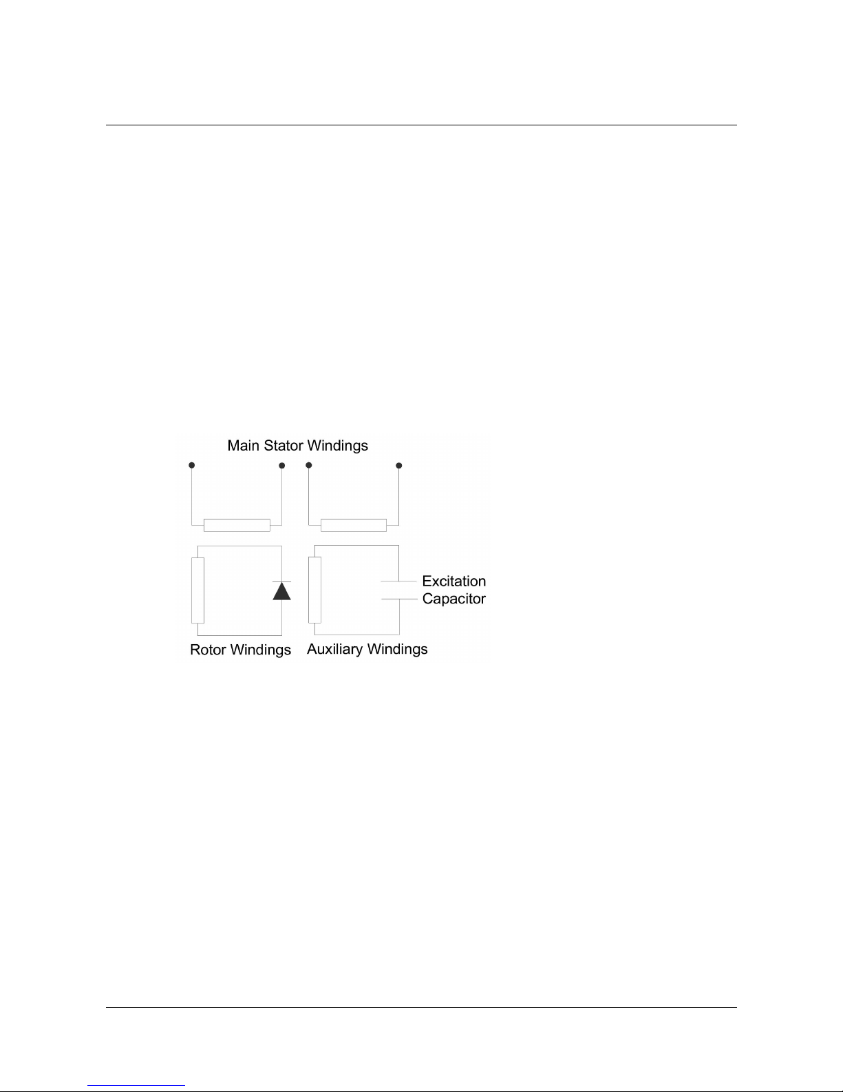
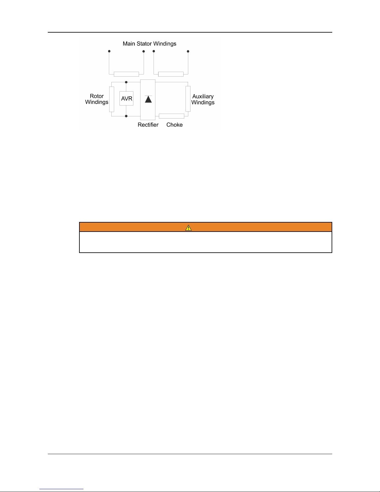
The BL105 is a self exciting brushless alternator designed to operate with single phase
loads at or near a power factor of 1.0. The principle of operation is schematically
represented in the figure below. The auxiliary winding, in conjunction with the excitation
capacitor, provides excitation by inducing current in the rotor (field) windings which is
rectified to produce a direct current field. The main stator winding is designed for
series/parallel connection to give a dual voltage output and no voltage adjustment is
possible.
4.3 SL105 Alternator
The SL105 alternator is of self-exciting, automatic voltage regulator (AVR) controlled,
rotating field design. It is designed to operate with close regulation when supplying single
phase loads. Primarily designed for loads at or near unity power factor, it has a capability of
operation at 0.8 power factor.
The principle of operation is schematically represented in the diagram below. The auxiliary
winding provides excitation power through a choke and rectifier into the rotating field via
sliprings.
The AVR diverts excess excitation at low loads to maintain the main stator winding output
voltage within close limits.
The main stator winding is designed for series/parallel connection to give a dual voltage
output with voltage adjustment.
The SL105 alternator may be supplied without a divertor AVR for specific applications. For
these alternators the instructions given in this manual for the SL105 alternator apply, but
references to the AVR or its control should be ignored.
A046V047 (Issue 1) 11
Page 16
-
4.4 Serial Number Location
A unique serial number is stamped into the upper section of the drive end bracket and
shown on two labels on the outside of the terminal box.
4.5 Rating Plate
The self-adhesive rating plate label, supplied with the alternator, must be fixed after the
generator set is fully assembled and painted.
WARNING
The alternator could overheat if operated outside the parameters specified on the rating plate.
Overheating can cause catastrophic failure and serious injury from ejected debris. Always
operate the alternator within the rated parameters.
12 A046V047 (Issue 1)
Page 17
5 Application of the Alternator
It is the customer's responsibility to make sure that the selected alternator is suitable for the
final application.
CAUTION
Overloading an alternator may lead to catastrophic failure.
5.1 Environment
MARKON alternators are protected to IP23 as standard. IP23 is not adequate protection for
use outdoors without additional measures.
Ambient Temperature -15 °C to 40 °C
Relative Humidity < 60%
Altitude < 1000 m
The alternator has been designed for the environment shown in the table. The alternator can
operate outside these conditions if it is rated accordingly: The nameplate gives details. If the
operating environment is changed after purchase, refer to the factory for a revised alternator
rating.
5.2 Air Flow
The alternator should be positioned so that the cooling air may enter and leave the machine
without restriction. Inadequate ventilation to the alternator will lead to serious overheating
and subsequent damage to windings.
5.3 Direction of Rotation
The alternator is suitable for either direction of rotation.
5.4 Drive Arrangement
All models are designed to suit engines having a drive shaft/crankcase mounting
arrangement to SAE J609a Flange A Extension 5 (3/4" Taper) or Flange B Extension 6 (7/8"
Taper) depending upon output kW.
Two bearing drive arrangements are available with a 22 mm diameter 45.5 mm long shaft
extension.
The minimum pulley pitch diameter to be used for belt driven application is 118 mm with a
maximum side loading of 700 N, to achieve full output and a reasonable bearing life. If
smaller pulleys are required refer to factory for maximum side load and bearing life. Where
single bearing to two bearing conversion parts have been supplied fitting instructions are
provided with the kit.
A046V047 (Issue 1) 13
Page 18

-
5.5 Road Vehicle Alternators
A special two bearing arrangement is used for this application to accommodate high bearing
loadings and vibration. The standard 22 mm diameter, 45.5 mm long shaft extension is
used.
The minimum pulley pitch diameter to be used is 118 mm with a maximum side loading of
1000 N.
5.6 Bearings
The bearing is preloaded and sealed for life and should require no further attention. Care
must be taken to ensure that the anti-creep circlip is correctly located in the groove before
mating with the end bell bearing housing, i.e. the bump on the circlip is in the deepest part of
the groove.
On two bearing machines the drive end bearing is a standard ball bearing sealed for life.
5.6.1 Road Vehicle Alternators
These alternators are fitted with larger bearings than standard. The drive end bearing is
clamped in the drive end bracket and the non drive end bearing is fitted in a steel housing
with an '0' ring to prevent turning.
5.6.2 Bearing Life
Factors that reduce bearing life or lead to bearing failure include:
• Adverse operating conditions and environment
• Stress caused by misalignment of the generator set
• Vibration from the engine that exceeds the limits in BS 5000-3 and ISO 8528-9
• Long periods (including transportation) where the alternator is stationary and subjected
to vibration can cause false brinelling wear (flats on the balls and grooves on the races)
• Very humid or wet conditions that cause corrosion and deterioration of the grease by
emulsification.
5.6.3 Health Monitoring of the Bearings
We recommend that the user checks the bearing condition, using vibration monitoring
equipment. Best practice is to take initial readings as a reference and periodically monitor
the bearings to detect a deteriorating trend. It will then be possible to plan a bearing change
at an appropriate generator set or engine service interval.
5.6.4 Bearing Service Life Expectancy
Bearing manufacturers recognize that service life of bearings depends on factors that are
outside their control: Rather than quote a service life, practicable replacement intervals are
based on the L10 life of the bearing, the type of grease and the recommendations of the
bearing and grease manufacturers.
For general-purpose applications; if the correct maintenance is carried out, vibration levels
do not exceed the levels stated in ISO 8528-9 and BS5000-3, and the ambient temperature
does not exceed 50°C, plan to replace the bearings within 30,000 hours of operation.
If in doubt about any aspect of bearing life on MARKON alternators, contact your nearest
supplier of MARKON alternators.
14 A046V047 (Issue 1)
Page 19
-
5.7 Earthing
The alternator is manufactured and delivered with the stator windings completely isolated
from the frame; a suitable earth terminal mounting point is provided on the bearing support
for bonding to the generating set frame.
Access to the earth terminal is gained by removal of the end cover.
5.8 Loading
The alternators are suitable for supplying, continuously, most types of load with a total load
current not exceeding the current quoted on the nameplate. Two points should be noted
however:
1. Engine Power.
The generator set output may be limited by the horsepower rating of the engine. As a
guide the engine has to supply approximately two horsepower for each 1000 watts (1
kW) of electrical load. Refer to factory for specific alternator efficiency.
2. Electric Motor Loads.
The current taken by a motor on full load is shown on its nameplate, but it will be
several times this value at the instant of starting even when there is no load on the
motor. The actual value depends on the type of motor and the starting current should
be checked before attempting to decide the size of alternator required.
When starting a motor the total current including any other load should not exceed twice the
full-load current of the alternator on BL105 models. The total current should not exceed 1.5
times the full-load current on SL105 models.
5.9 Vibration
MARKON alternators are designed to withstand the vibration levels encountered on
generator sets built to meet the requirements of ISO 8528-9 and BS 5000-3. (Where ISO
8528 is taken to be broad band measurements and BS5000 refers to the predominant
frequency of any vibrations on the generator set).
NOTICE
Exceeding either of the above specifications will have a detrimental effect on the life of the
bearings and other components, and may invalidate the alternator warranty.
NOTICE
The terminal box is designed to support the fitted busbars or terminals,
transformers, load cables and auxiliary terminal box. Additional mass could cause
excessive vibration and lead to failure of the terminal box enclosure and mounting.
Refer to Bad link:
/opt/dzd/dzd_prog/prog_docato/docato_4.9.1/docato/work/temp/dzd_temp/topleaf/5e2
def30-91b6-40b5-93db-37ff38e651d5/enus/cgt/installation/electricalconnection_title.xml to connect the load cables to the
terminal box. Refer to CGT before fixing any additional mass to the terminal box.
A046V047 (Issue 1) 15
Page 20
-
5.9.1 Definition of BS5000–3
Alternators shall be capable of continuously withstanding linear vibration levels with
amplitudes of 0.25mm between 5Hz and 8Hz and velocities of 9.0mm/s r.m.s. between 8 Hz
and 200 Hz, when measured at any point directly on the carcass or main frame of the
machine. These limits refer only to the predominant frequency of vibration of any complex
waveform.
5.9.2 Definition of ISO 8528-9
ISO 8528-9 refers to a broad band of frequencies; the broad band is taken to be between 10
Hertz and 1000 Hertz. The table below is an extract from ISO 8528-9 (Table C.1, value 1).
This simplified table lists the vibration limits by kVA and speed for acceptable operation of
standard generator set designs.
5.9.3 Excessive Vibration
WARNING
Excessive vibration can cause catastrophic failure of the alternator, which could cause
personal injury.
If the measured vibration of the generator set is not within the limits:
1. The generator set manufacturer should change the generator set design to reduce the
vibration levels as much as possible.
2. Contact Cummins Generator Technologies to assess the impact on bearing and
alternator life expectancy.
16 A046V047 (Issue 1)
Page 21
6 Installation into the Generator Set
6.1 Safety Warnings
WARNING
Refer to local regulations to ensure that the correct earthing procedure has been followed
The alternator is supplied as a component part for installation on a generating set and it is
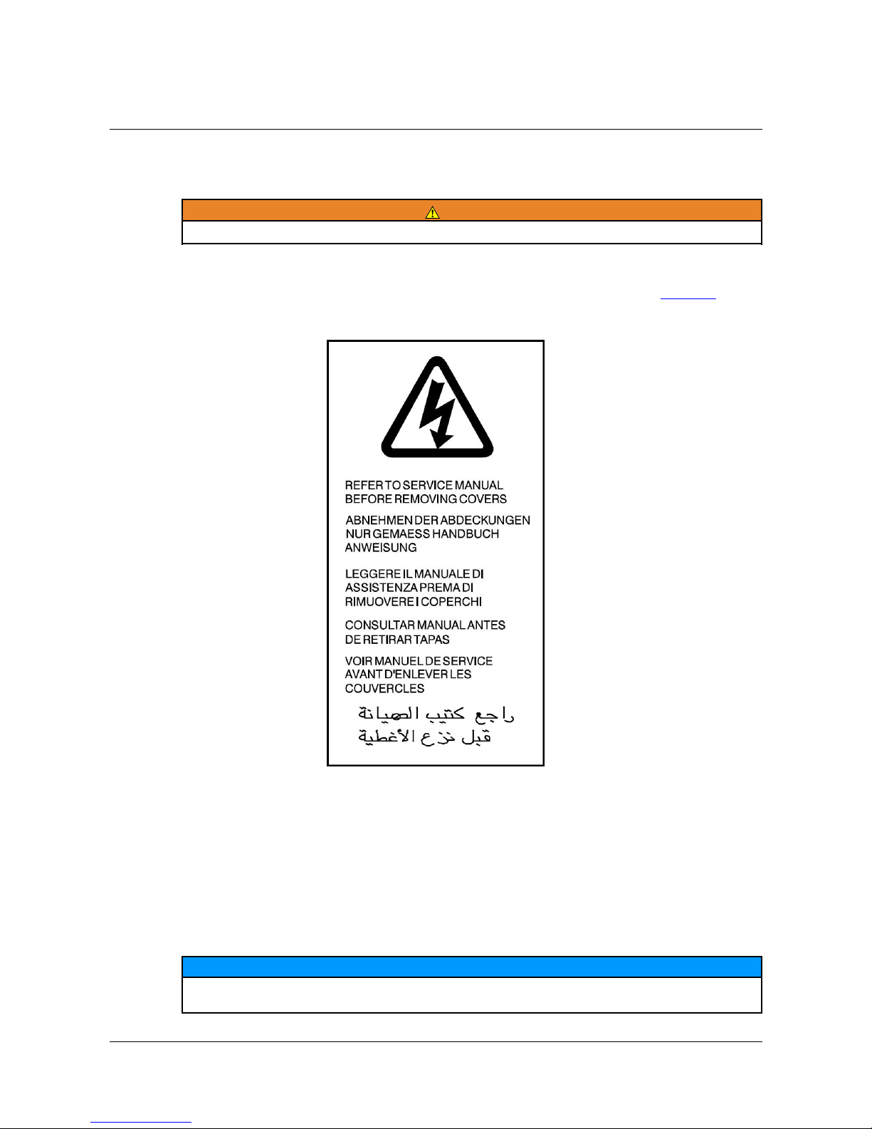
the responsibility of the generating set builder to fit the safety warning label, Figure 3, which
is supplied packaged with this manual. The label should be attached to the alternator in a
position where it is clearly visible on the generating set.
FIGURE 3. SAFETY WARNING LABEL
6.2 Inspection
When the equipment is received, all details, especially the Serial Number of the alternator,
should be checked against the Advice Note. Carefully remove all dust and packing
materials. In the event of any part being damaged ormissing, this should be reported at once
to the manufacturer and the transport company. Always quote the Serial Number on
correspondence with the manufacturer.
NOTICE
When nameplates are supplied packaged with the machine, but not fitted, it is the
responsibility of the installer to fit the nameplate to the alternator.
A046V047 (Issue 1) 17
Page 22

-
6.3 Storage
If the alternator is not to be used immediately, it must be stored in a clean, dry, vibration free
environment. We recommend the use of anti-condensation heaters, when available.
Refer to Service and Maintenance section (Chapter 7 on page 21) of this manual for further
instructions for the bearings of stored alternators.
6.3.1 After Storage
After a period of storage, carry out the pre-running checks to determine the condition of the
windings. If the windings are damp or the insulation resistance is low, follow one of the
drying out procedures (see Chapter 7 on page 21).
• For sealed bearings that have been in storage for more than 12 months, replace the
bearings before first use of the alternator.
6.4 Coupling To The Engine
Refer to Assembly/Dismantling Procedure Section 7.5.
6.5 Electrical Connections
The alternators are supplied from the factory with flying leads from the main stator windings.
The BL105 & SL105 may be permanently connected or switched in the generator set outlet
box to obtain the required output voltage(s). The installer must provide necessary overload
protection. The windings are not bonded to the machine frame and it is the responsibility of
the installer to provide suitable bonding to earth. Reference should be made to relevant site
or safety regulations.
Note that the point of earthing the stator winding is at the discretion of the installer.
• Normally a 230 volt 2 wire output will be earthed at one end giving a maximum of 230
volts to earth (Or 115 volts in parallel mode).
• A 110 volt 2 wire output will normally be earthed at the centre tap (series connection
point) giving a maximum of 55 volts to earth.
• Reference should be made to relevant site or safety regulations.
6.6 Voltage Selection
6.6.1 Dual Voltage Output for 4 Lead Models
The main stator windings are in two sections which may be connected in series or parallel to
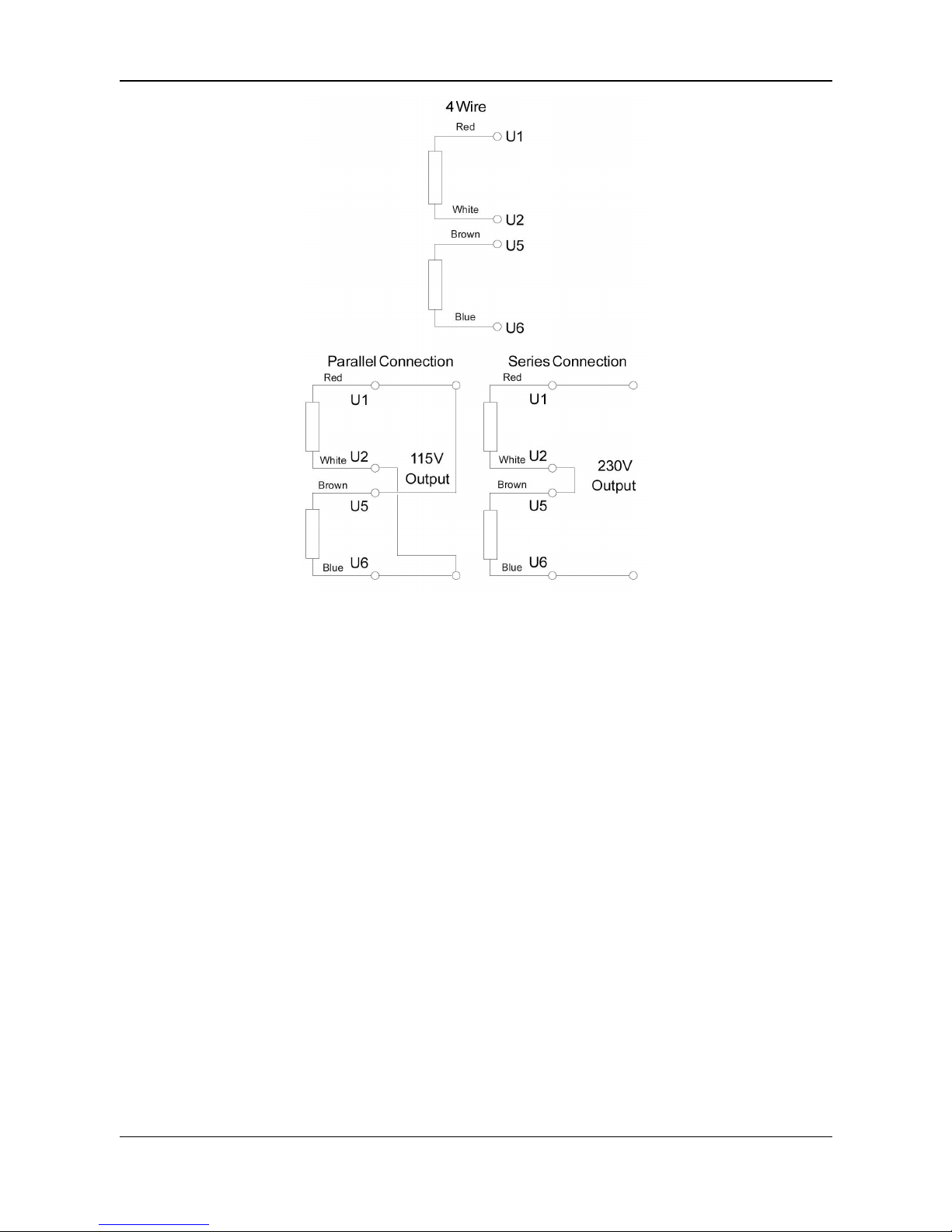
give a choice of output voltage. For example, series connection gives 230 V, parallel
connection gives 115 V.
This is illustrated below Figure 4 on page 19. Each winding section is capable of carrying
the same current, I. When the windings are connected in series the maximum load current is
I, but when the windings are connected in parallel the maximum current is 2 X I.
Example:
A 2.5 kVA alternator when connected in series for 230 V operation has a capacity of 10.9 A;
when connected in parallel for 115 V it has a capacity of 21.7 A.
18 A046V047 (Issue 1)
Page 23
-
FIGURE 4. DUAL VOLTAGE EXAMPLE
6.6.2 110V CTE Output (BL105 range only)
The main stator windings are in two sections which should be connected in series to give
110 V output, with the centre tap taken from the series connection point.
6.7 Voltage Adjustment For The SL105 - AVR MD1C
The voltage is set during manufacture to give the mid-voltage of the range of voltages
shown on the nameplate, ie: an alternator whose nameplate is marked 220-240 / 110-120 V
will be set to give 230 volts with the output windings connected in series and 115 volts when
connected in parallel.
The voltage may be reset to any value within the nameplate range. To RAISE the voltage
turn the volts adjust potentiometer VR1 CLOCKWISE and to LOWER the voltage turn the
potentiometer ANTI-CLOCKWISE.
The volts adjust potentiometer is the one at the bottom of the board.
6.8 Pre-Running Checks
Before starting the generator set, test the insulation resistance of windings, check all
connections are tight and in the correct location. Ensure the alternator air path is clear of
obstructions. Replace all covers.
A046V047 (Issue 1) 19
Page 24

-
6.9 Stability
This control should not normally require adjustment having been set during manufacture, but
should the output voltage fluctuate with a steady load connected, this may be improved by
turning the potentiometer anti-clockwise which will increase the damping effect.
NOTICE
Do not use undue force when turning the potentiometers - they can be damaged by
attempting to adjust beyond the internal stops.
When making either adjustment the speed must be correct.
6.10 Varying Load
Under certain conditions, load variations can reduce alternator life.
Identify any possible risk, especially the following:
• Large capacitive loads (for example Power Factor Correction equipment) can affect
alternator stability and cause pole slip.
• Stepped grid voltage variation (for example Tap Changing).
If the alternator is at risk from varying load, include adequate protection into the generator
set system by under-excitation protection.
20 A046V047 (Issue 1)
Page 25

7 Service and Maintenance
7.1 General
WARNING
The following procedures present hazards which can result in personal injury or death. Only
persons qualified to carry out electrical and mechanical servicing should undertake this
work.
The BL model alternator is fitted with sealed for life bearings and requires no regular
maintenance.
The SL model alternator similarly requires no regular mechanical maintenance. It is,
however, fitted with slip-rings and brushgear which require regular attention.
Inspect brushes and sliprings at 500 hour intervals. Replace brushes when they are worn to
a depth of 8 mm. The new brush should be bedded using a medium grade abrasive cloth. If
the sliprings are pitted or badly marked the rotor should be removed and the sliprings lightly
skimmed.
The alternator must periodically be inspected and any accumulation of dirt or oil must be
removed. Air inlet and outlet openings must be kept unobstructed.
For BL and SL models it is recommended that:-
1. After storage or long periods of standing idle the condition of windings should be
checked. Refer to 'Insulation Resistance Check' Section 7.2
and
2. During generating set overhaul, the bearing is replaced. Refer to Assembly/Dismantling
Procedure, Section 7.5.
7.2 Insulation Resistance Test
If the equipment has been stored or allowed to get damp the insulation resistance of the
windings should be checked.
On BL models before carrying out this test disconnect the capacitor and any earthed
connections.
On SL models disconnect AVR, rectifier, RI suppressor [17] and any earthed connections.
The check should be carried out on the stator winding between each winding group and the
alternator frame, and between the rotor winding and rotor core using a 500 volt Megger or
similar instrument. The resistance value obtained should be at least one megohm. If the
resistance is less than one megohm the windings should be dried out in a warm
atmosphere. The resistance values should be rechecked every 30 minutes until this value is
obtained.
7.3 Residual Voltage/Field Flashing
If the rotor has been removed, the alternator stored for a considerable time or the rotor
(field) connections reversed during servicing, the residual magnetism may have been
destroyed.
To check residual voltage, remove the end cover for access.
A046V047 (Issue 1) 21
Page 26
-
Remove capacitor leads (BL Model) or Z2 from the rectifier assembly (SL Model).
Run the alternator at normal no-load speed. Measure the voltage as indicated below:
• Model BL105 across output leads U1 6 U2 Voltage 1.5 (min)
• Model SL105 across output leads U1 6 U2 Voltage 1.5 (min)
7.3.1 BL Model
Reconnect capacitor leads to original position. Run alternator at normal no-load speed. A 12
volt battery should then be instantaneously flashed (that is connected for only one second)
across the capacitor. The auxiliary leads must still be connected to the capacitor. The output
voltage should then build up to the normal no-load level.
7.3.2 SL Model
Reconnect lead Z2 to rectifier assembly and disconnect leads Fl - F2. Run alternator at
normal no-load speed and apply a 12 volt supply, from the battery, to the brush -holder for
about 3 seconds. Ensure the positive lead is applied to the brush holder nearest the bearing
housing.
The output voltage of the alternator, with the 12 volt supply connected, should be
approximately normal voltage. Stop the alternator and reconnect leads Fl - F2.
NOTICE
Important ! Ensure the battery leads are connected to the brush holder with the correct
polarity, and leads Fl - F2 are isolated from each other and earth.
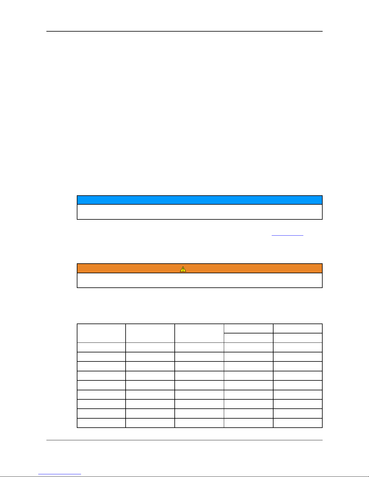
Check windings for continuity and resistance values to the following table Section 7.4.
7.4 Resistance Charts
WARNING
Replace all guards and protective covers after servicing. Failure to do so may result in
operator personal injury.
All figures are approximate values in ohms.
TABLE 1. 50HZ WINDINGS RESISTANCE VALUES
MODEL VOLTAGE ROTOR MAIN STATOR AUXILLIARY
PER SECTION WINDING
BL105A 240/120 7.88 1.964 1.291
BL105A 220/110 7.88 1.613 1.291
BL105A 230/115 7.88 2.15 1.48
BL105B 240/120 4.13 1.805 1.16
BL105B 230/115 4.13 1.65 1.16
BL105B 230/115 4.13 1.65 1.13
BL105C 240/120 8.60 1.49 1.21
BL105C 220/110 8.60 1.36 1.21
BL105C 230/115 8.60 1.43 1.21
22 A046V047 (Issue 1)
Page 27
-
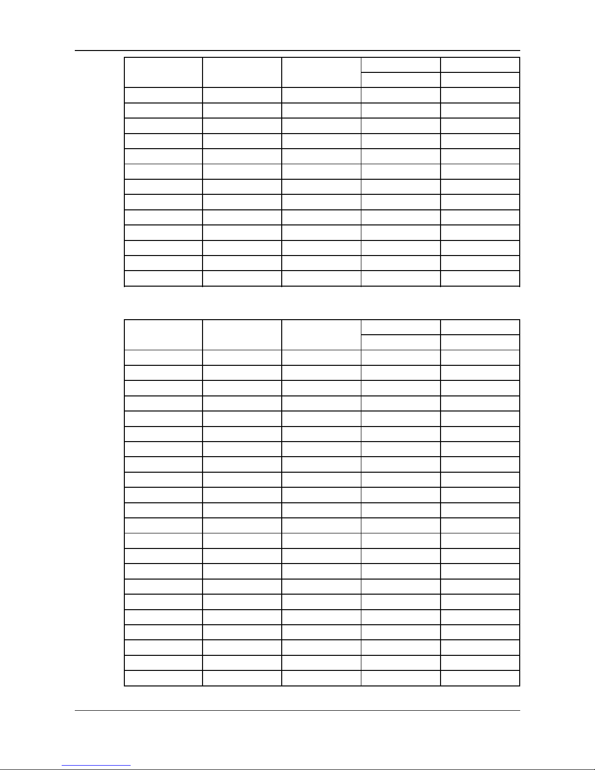
MODEL VOLTAGE ROTOR MAIN STATOR AUXILLIARY
PER SECTION WINDING
BL105E 240/120 9.57 0.954 1.16
BL105E 230/115 9.57 0.911 1.21
BL105F 240/120 10.05 0.753 0.926
BL105F 220/110 10.05 0.666 0.926
BL105F 230/115 10.05 0.684 0.991
BL105G 240/120 10.53 0.669 0.862
BL105G 220/110 10.53 0.489 0.829
SL105A 230/115 11.13 2.641 4.24
SL105B 230/115 11.66 1.58 4.227
SL105C 230/115 12.15 1.326 3.18
SL105E 230/115 10.66 0.858 2.155
SL105F 230/115 11.31 0.726 1.935
SL105G 230/115 11.85 0.565 1.771
TABLE 2. 60HZ WINDINGS RESISTANCE VALUES
MODEL VOLTAGE ROTOR MAIN STATOR AUXILLIARY
PER SECTION WINDING
BL105A 240/120 7.88 1.467 0.906
BL105A 220/110 7.88 1.182 0.906
BL105B 240/120 4.13 1.27 0.826
BL105B 220/110 4.13 1.27 0.826
BL105B 240/120 4.13 1.65 1.16
BL105C 240/120 8.60 1.09 0.873
BL105C 220/110 8.60 0.89 0.873
BL105E 240/120 9.57 0.693 0.82
BL105E 220/110 9.57 0.553 0.82
BL105E 240/120 9.57 0.656 0.82
BL105F 240/120 10.05 0.554 0.789
BL105F 220/110 10.05 0.436 0.66
BL105G 240/120 10.53 0.467 0.646
BL105G 220/110 10.53 0.41 0.646
BL105G 230/115 10.53 0.607 0.829
SL105A 240/120 11.13 1.934 4.24
SL105B 240/120 11.66 1.206 3.758
SL105C 240/120 12.15 0.971 3.18
SL105E 240/120 10.66 0.665 1.946
SL105F 240/120 11.31 0.5 1.756
SL105G 240/120 11.85 0.397 1.735
SL105G 240/120 11.85 0.423 1.624
A046V047 (Issue 1) 23
Page 28

-
7.5 Assembly/Dismantling Procedure
Component identification numbers refer to those shown in Chapter 9 on page 33.
7.5.1 Assembling Alternator To Engine
1. Apply LOCTITE 'THREADLOCK' or equivalent to one end of the shaft securing stud [1].
Fit this end of the shaft securing stud [1] into the engine shaft, ensuring the full length of
thread is engaged.
2. Fit appropriate engine adaptor plate and fit studs supplied into the alternator side of the
adaptor plate and tighten.
3. Remove end cover fixing screws [2] and end cover [3].
4. Remove transit bolt from shaft end and discard both bolt and large washer.
NOTICE
On SL and TL models care must be taken to avoid damage to the carbon brushes by
excessive axial movement of the rotor. Lift brushes if in doubt.
5. Offer stator frame assembly [4] complete with rotor assembly up to the engine, feeding
rotor over securing stud and frame on to the adaptor studs. Tap frame over the adaptor
spigot.
6. Fit nuts and washers securing the frame to the adaptor studs and tighten.
7. Fit the 5/16" UNF SELF LOCKING nut ( Shaft Securing Nut ) [5] to the shaft securing
stud [1] and tighten.
8. Replace end cover [3].
9. Secure stator frame assembly to the bedplate foot fixing(s). Where the stator frame
assembly is rigidly mounted to the bedplate, shims must be fitted to ensure accurate
alignment.
Refer to Section 7.5.13 on page 28 for torque settings.
7.5.2 Dismantling Stator Frame Assembly
NOTICE
On SL models remove end cover fixing screws [2] and end cover [3] and lift brushes [12]
(part of brushbox assembly).
1. Remove nuts securing frame to adaptor studs.
2. Remove feet fixing bolts (or nuts).
3. Tap frame away from the engine to release the adaptor spigot. Withdraw stator frame
assembly over the rotor.
7.5.3 Withdrawing Rotor From Engine
1. Remove the shaft securing nut [5].
2. Release rotor from engine taper shaft by supporting rotor in one hand and with a hide /
soft faced mallet striking firmly on a pole face.
NOTICE
Do not use the fan [6] to prevent the rotor turning when releasing the shaft securing nut.
24 A046V047 (Issue 1)
Page 29

-
7.5.4 Removal/Replacement of Capacitor - BL Models
1. Remove end cover fixing screws [2] and end cover [3] and disconnect capacitor leads.
2. Remove capacitor fixing nut [11] and cut nylon tie support [12].
3. Remove capacitor [13].
Replacement is a reversal of removal.
7.5.5 Removal/Replacement of Rectifier Hub - Single Diode
NOTICE
Take careful note of connections and positions of the solder tags before carrying out the
following procedure. Incorrect polarity of the diode varistor assembly will destroy residual
magnetism.
1. Rotor must be removed from the alternator/engine to carry out this procedure Section
7.5.3.
2. Remove Non-Drive End bearing from rotor shaft.
3. Carefully cut the ties which hold the winding wires in place.
4. Unsolder all leads from the diode
5. Using a hammer and chisel, knock off the old hub assembly, (this may require a
significant amount of effort owing to the hub being held in place by adhesive).
6. Using abrasive paper, remove any excess old adhesive from the shaft where the hub
was located. Do this until the new hub slides with ease into the correct position.
7. Apply a fast drying adhesive (LOCTITE 648 used in conjunction with Activator N
LOCTITE 7649 is recommended) to the shaft where the new hub will be located.
8. Slide the new hub into position, turning it through 360°, two or three times to ensure an
even film over the entire shaft.
9. Push the hub into place make sure that the diode is located centrally between the two
coils.
10. Allow approximately 10 minutes for theadhesive to harden and then proceed to resolder all the wires to the diode as described below:
With the rotor standing upright, resting on the fan and the diode facing you, take the
nearest two wires from the coil along with one from the varistor and one from the
snubber and solder them to the top pin of the diode. Take the other two wires from the
coils and the wire from the snubber and solder them to one of the bottom tags. Take
the remaining varistor wire and solder it to the other bottom diode tag.
11. Re-fit the bearing, ensuring the anti-creep groove is located closest to the hub.
12. Re-assemble rotor into stator/frame assembly.
13. As the rotor has been removed from the stator it will probably need to be flashed to put
the residual magnetism back into it.
7.5.6 Removal/Replacement of Rectifier Hub - Twin Diodes
NOTICE
Take careful note of connections and positions of the solder tags before carrying out the
following procedure. Incorrect polarity of the diode varistor assembly will destroy residual
magnetism.
A046V047 (Issue 1) 25
Page 30

-
NOTICE
1. Rotor must be removed from the alternator/engine to carry out this procedure Section
7.5.3.
2. Remove Non-Drive End bearing from rotor shaft.
3. Carefully cut the ties which hold the winding wires in place.
4. Unsolder all leads from both diodes
5. Using a hammer and chisel, knock off the old hub assembly, (this may require a
significant amount of effort owing to the hub being held in place by adhesive).
6. Using abrasive paper, remove any excess old adhesive from the shaft where the hub
was located. Do this until the new hub slides with ease into the correct position.
7. Apply a fast drying adhesive (LOCTITE 648 used in conjunction with Activator N
LOCTITE 7649 is recommended) to the shaft where the new hub will be located.
8. Slide the new hub into posistion, turning it through 360°, two or three times to ensure
an even film over the entire shaft .
9. Push the hub into place make sure that the diodes are located between the two coils
10. Allow approximately 10 minutes for the adhesive to harden and then proceed to resolder all the wires to the diodes as described below:
With the rotor standing upright, resting on the fan, take the wire from the right-hand coil
and solder it to the centre stem pin of the diode facing you. Take the other wire from
the same coil and solder it to one of the diode tags. Make sure the remaining varistor
wire is soldered to the other diode tag.
Turn the rotor 180° and repeat for the other diode.
11. Re-fit the bearing, ensuring the anti-creep groove is located closest to the hub.
12. Re-assemble rotor into stator/frame assembly.
13. As the rotor has been removed from the stator it will probably need to be flashed to put
the residual magnetism back into it.
7.5.7 Removal/Replacement of AVR - SL Models
1. Remove end cover fixing screws [2] and end cover [3].
2. Disconnect the four leads (three black and one grey) from the four spade terminals on
the right hand side of the AVR, taking note that the grey lead is always connected to
the terminal marked F1.
3. Remove the three AVR fixing screws [13] and remove AVR [14 ].
Replacement is a reversal of removal. Ensure that the leads to the AVR are correctly
replaced and the grey lead is connected to terminal F1.
If grey (F1) and black (F2) leads are reversed it will be necessary to flash the field when
restarting. Refer to Section 7.3 on page 21.
7.5.8 Removal/Replacement of Diode Bridge - SL Models
NOTICE
Note positions of leads on the assembly before removal.
1. Remove end cover fixing screws [2] and end cover [3].
26 A046V047 (Issue 1)
Page 31

-
2. Remove leads from diode bridge [16]. Remove diode bridge fixing screw [22] and
remove diode bridge.
Replacement is a reversal of removal.
7.5.9 Removal/Replacement of Choke - SL Models
1. Remove end cover fixing screws [2] and end cover [3].
2. Remove diode bridge fixing screws [22].
3. Lift away choke and remove connecting leads. Remove choke [15].
Replacement is a reversal of removal.
7.5.10 Removal/Replacement of Radio Interference Suppressor
(RIS) - SL Models When Applicable
1. Remove connecting leads.
2. Remove RIS fixing screw [19] and remove RIS [17].
Replacement is a reversal of removal.
NOTICE
Ensure that the RIS spacer [20] is fitted between the RIS and frame.
7.5.11 Removal/Replacement of Bearing
NOTICE
On SL Models ensure brushes are lifted before attempting to refit the rotor assembly into the
stator frame assembly.
1. With the rotor withdrawn, use a standard bearing puller to remove the bearing from the
shaft.
2. Place new bearing squarely on the shaft end with anti-creep circlip groove inboard and
drift into place using a suitably sized soft tubular drift on the bearing inner race.
Care must be taken to ensure that the anti-creep circlip is correctly located in the
groove before mating with the bearing housing, i.e. the bump on the circlip is in the
deepest part of the groove.
3. Refit the rotor assembly into the stator frame assembly taking care to avoid damaging
wound components.
4. Locate the bearing in the housing and tap into position.
5. Assemble alternator to engine. Refer to Section 7.5.1 on page 24.
7.5.12 Removal/Replacement of Brushes/BrushBox Assembly SL Models
1. Remove end cover fixing screws [2] and end cover [3].
2. On SL models remove AVR [14]. Refer to Section 7.5.7 on page 26.
3. Remove fixing screw [21 ] and lift away brushbox assembly.
Replacement is a reversal of removal.
A046V047 (Issue 1) 27
Page 32

-
On SL models refit AVR as detailed in Section 7.5.7 on page 26.
If brushes only are to be changed remove brush terminal plate and withdraw springs and
brushes. New brushes must be bedded using a medium grade abrasive cloth.
7.5.13 Torque Settings
CAUTION
After servicing ensure all protective guards and access covers are fitted. Failure to do so can
result in operator injury.
Adaptor to engine - Refer to engine manufacturer.
Adaptor to frame - 5.4 Nm (0.55 kgf.m)
Shaft securing nut - 20.4 Nm (2.1 kgf.m)
7.5.14 After Sales Service
A full technical advice and on-site service facility is available from our Service Department in
Oakham or through our Subsidiary Companies.
Call for quotation.
28 A046V047 (Issue 1)
Page 33

8 Fault Finding
DANGER
Hazardous voltage.
Will shock, burn or cause death.
Fault finding methods include tests on live electrical conductors carrying high voltage. Risk
of serious injury or death by electric shock. Fault finding must be done by competent,
qualified persons trained in safe working practices.
Assess risk and work on or near live conductors only if absolutely necessary. Do not work on
or near live conductors alone; another competent person must be present, trained to isolate
energy sources and take action in an emergency.
Place warnings and prevent access to test area by unauthorized persons.
Make sure that tools, test instruments, leads and attachments are designed, inspected and
maintained for use on the maximum voltages likely under normal and fault conditions.
Take suitable precautions to prevent contact with live conductors, including personal
protective equipment (PPE), insulation, barriers and insulated tools.
Before starting any fault finding procedure, examine all wiring for broken or loose
connections. If in doubt, refer to the wiring diagram supplied with the alternator. Compare
measurements with the test report supplied with the alternator.
The following list is to aid in troubleshooting and is not exhaustive. If in doubt, consult
Cummins service department.
8.1 Fault Finding Procedures
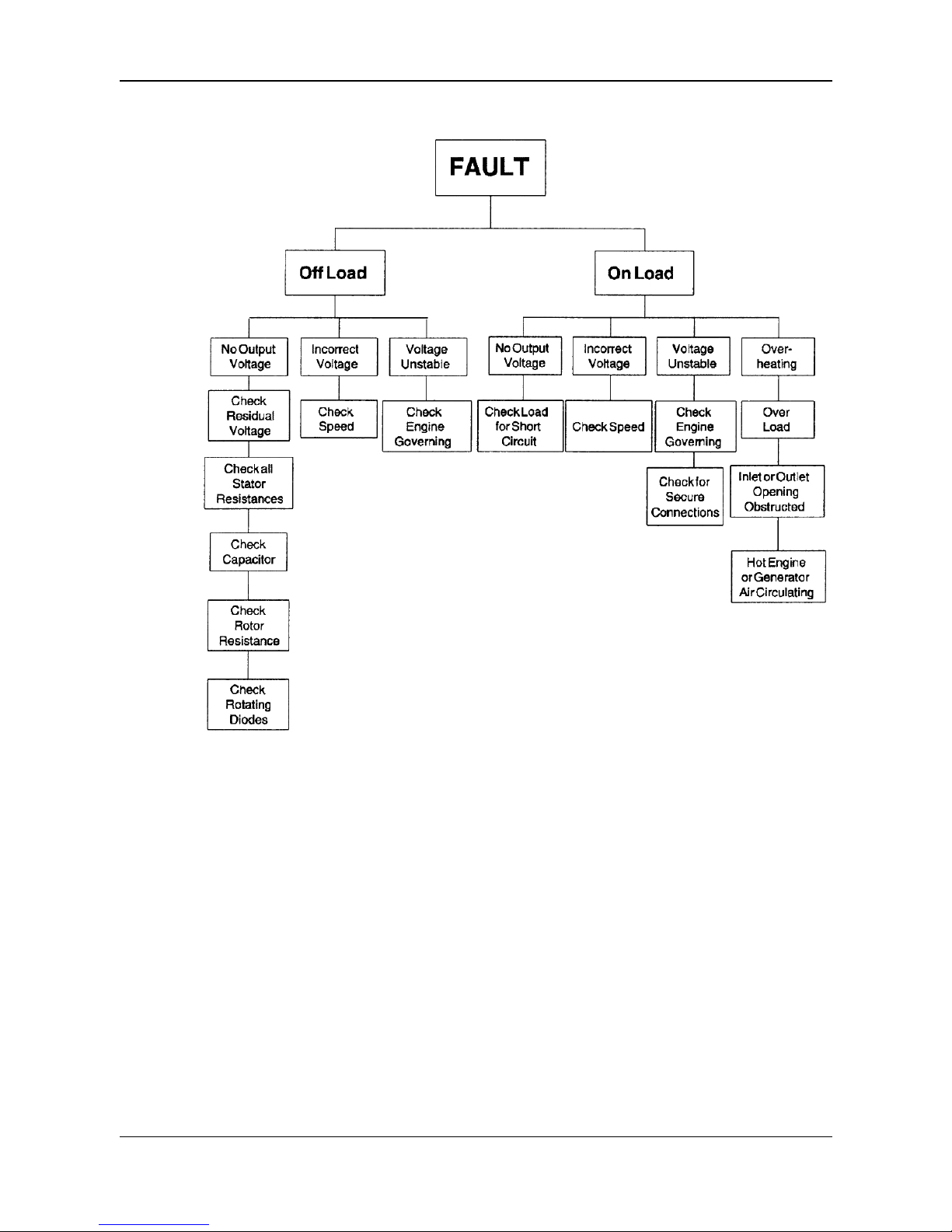
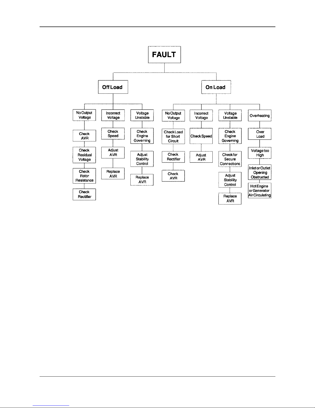
Should a fault develop during operation it is best identified by carrying out the checks
identified in the following fault finding guides.
Refer to Assembly / Dismantling section when attempting to replace components.
Before proceeding always check security of all connections, especially those to control
equipment and / or AVR.
On SL models remove air intake cover and check condition of the sliprings, the freedom of
movement of brushes, brush spring tension and amount of brushwear. Brushes should not
be less than 8 mm long.
A046V047 (Issue 1) 29
Page 34
-
8.2 BL Model - Fault Finding Guide
30 A046V047 (Issue 1)
Page 35
-
8.3 SL Model - Fault Finding Guide
A046V047 (Issue 1) 31
Page 36

-
This page is intentionally blank.
32 A046V047 (Issue 1)
Page 37
9 Parts Identification
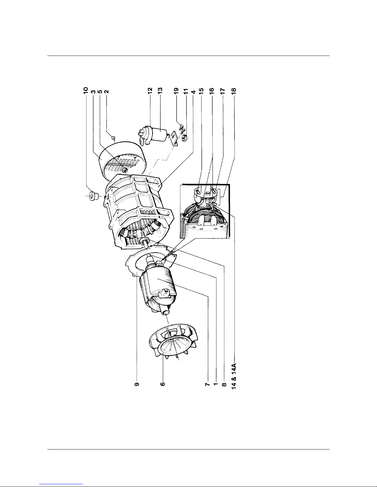
9.1 BL105 Alternator - Single Bearing
A046V047 (Issue 1) 33
Page 38

-
TABLE 3. BL105 ALTERNATOR - SINGLE BEARING
Plate Description Part Numbers
Ref
1 SHAFT SECURING STUD Various
2 END COVER FIXING SCREWS 005-04053
3 END COVER ( PLASTIC ) 14-116 / 1
3 END COVER ( STEEL) 240-20344
4 STATOR FRAME ASSEMBLY Various
5 SHAFT SECURING NUT 018-001
6 FAN 240-10213
7 WOUND ROTOR ASSEMBLY Various
8 BEARING 014-040
9 AIR BAFFLE 240-10127
10 INSULATING BUSH 016-016
11 CAPACITOR FIXING NUT With Capacitor
12 CAPACITOR SUPPORT BRACKET 240-10120
13 CAPACITOR ( 40uf ) 009-093
14 DIODE (Forward) 800v 002-022
14a DIODE (Reverse) 800v 002-023
14b DIODE ( Single Diode Type ) 1200v 073-50042
15 VARISTOR 073-08160
16 SOLDER TAG 020-131
17 DIODE / VARISTOR CARRIER HUB 20-205 / 1
18 DIODE / VARISTOR HUB ASSEMBLY ( 2 B105Z-11001
Diode Type )
18a DIODE / VARISTOR HUB ASSEMBLY ( 240-10335
1Diode Type )
18b DIODE / VARISTOR HUB ASSEMBLY ( PCB 240-10336
Type )
19 CAPACITOR BRACKET FIXING SCREW 005-04084
34 A046V047 (Issue 1)
Page 39
-
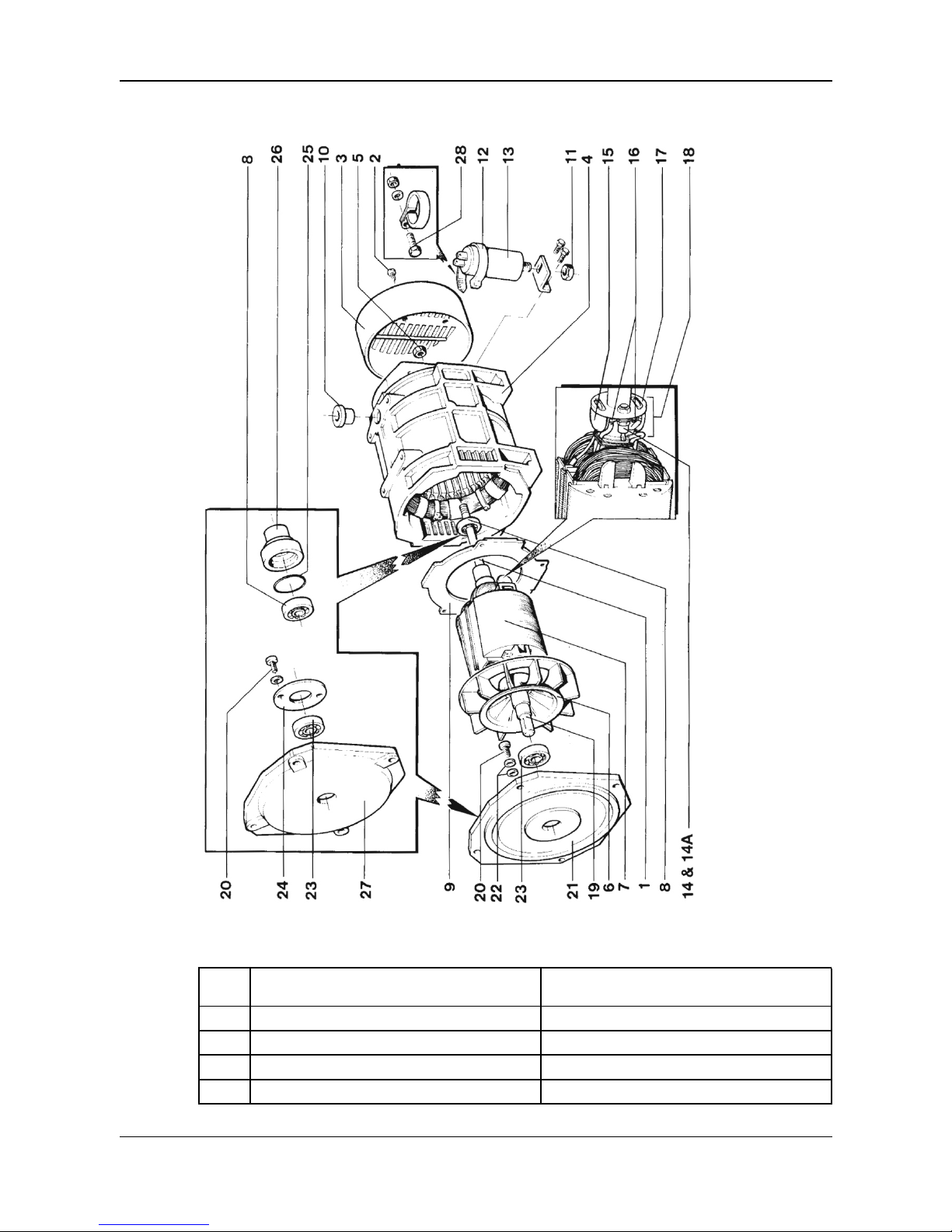
9.2 BL105 Alternator - Two Bearing
TABLE 4. BL105 ALTERNATOR - TWO BEARING
Plate Description Part Numbers
Ref
1 SHAFT SECURING STUD* 240-20618 or 240-20624
2 END COVER FIXING SCREWS 005-04053
3 END COVER 14-116 / 1 or 240-20344
4 STATOR FRAME ASSEMBLY Various
A046V047 (Issue 1) 35
Page 40

-
Plate Description Part Numbers
Ref
5 SHAFT SECURING NUT* 018-001
6 FAN 240-10213
7 WOUND ROTOR ASSEMBLY Various
8 BEARING — NON DRIVE END 014-040* / 014-041**
9 AIR BAFFLE 240-10127
10 INSULATING BUSH 016-016
11 CAPACITOR FIXING NUT With Capacitor
12 CAPACITOR SUPPORT 240-10120
13 CAPACITOR ( 40uf ) 009-093
14 DIODE (See Single Bearing parts list)
15 VARISTOR 073-08160
16 SOLDER TAG 020-131
17 DIODE / VARISTOR CARRIER HUB 20-205 / 1
18 DIODE / VARISTOR HUB ASSEMBLY (See Single Bearing parts list)
19 STUB SHAFT* 05-416 / 1 or 05-417 / 1
20 BEARING RETAINING SCREW 016-40717
21 D.E.BRACKET Various
22 BEARING RETAINING WASHER* 501-016
23 BEARING — DRIVE END 014-003* / 014-042**
24 BEARING RETAINING WASHERS** 501-057
25 0' RING** 019-014
26 BEARING HOUSING** 240-10154
27 D.E.BRACKET** Various
36 A046V047 (Issue 1)
Page 41
-
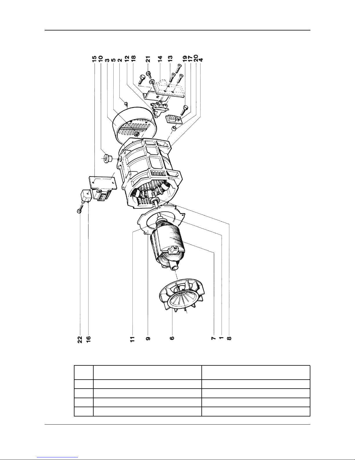
9.3 SL105 Alternator
TABLE 5. SL105 ALTERNATOR
Plate Description Part Numbers
Ref
1 SHAFT SECURING STUD Various
2 END COVER FIXING SCREWS 005-04053
3 END COVER ( PLASTIC ) 14-116 / 1
3 END COVER ( STEEL) 240-20344
A046V047 (Issue 1) 37
Page 42

-
Plate Description Part Numbers
Ref
4 STATOR FRAME ASSEMBLY Various
5 SHAFT SECURING NUT 018-001
6 FAN 240-10213
7 WOUND ROTOR ASSEMBLY Various
8 BEARING 014-040
9 AIR BAFFLE 240-10127
10 INSULATING BUSH 016-016
11 SLIPRINGS 013-001
12 BRUSHBOX ASSEMBLY 011-008
13 AVR FIXING SCREWS 504-163
14 AUTOMATIC VOLTAGE REGULATOR 036-245
(AVR)
15 CHOKE 240-20346
16 DIODE BRIDGE 002-058
17 RADIO NTERFERENCE SUPPRESSOR 036-115
(RIS)
18 BRUSHBOX MOUNTING PLATE 240-10126
19 RIS FIXING SCREW 005-04076
20 RIS INSULATING SPACER 240-1 01 37
21 BRUSHBOX FIXING SCREW 016-40613
22 DIODE BRIDGE FIXING SCREW 005-04076
38 A046V047 (Issue 1)
Page 43
10 Service Parts and After Sales Service
10.1 Recommended Spares
Service parts are conveniently packaged for easy identification.
We recommend the following for service and maintenance. In critical applications a set of
these service spares should be held with the alternator.
TABLE 6. BL105 MODELS
Description Part No. Quantity
1 Capacitor 009-093 1
2 NDE Bearing 014-040 1
3 NDE Bearing - R.V.A. 014-041 1
4 DE Bearing - 2 Bearing 014-003 1
5 DE Bearing - R.V.A. 014-042 1
6 Diode Varistor Assembly B105Z-11001 or 1
240-10335 (Snubber) or
240-10336 (PCB)
NOTICE
R.V.A. refers to Road Vehicle Alternator.
TABLE 7. SL105 MODELS
Description Part No. Quantity
1 AVR MD1C 036-245 1
2 Diode Bridge 002-058 1
3 NDE Bearing 014-040 1
4 DE Bearing - 2 Bearing 014-003 1
5 Brushbox (including brushes) 011-008 1
6 Carbon Brush with spring 010-026 2
When ordering spare parts the machine serial number and type should be quoted, together
with the part description. The serial number is on the side of the alternator.
Orders and enquiries for parts should be addressed to:
Cummins Generator Technologies Mexico
Av. Circuito Mexico No. 185
Parque Industrial 3 Naciones
San Luis Potosi, SLP
C.P. 78395
Tel: +52 444 870 4400
Fax: +52 444 870 4471
A046V047 (Issue 1) 39
Page 44

-
10.2 After Sales Service
A full technical advice and on-site service facility is available from our Service Department in
Oakham or through our Subsidiary Companies.
Call for quotation.
40 A046V047 (Issue 1)
Page 45

11 End of Life Disposal
Companies specializing in reclaiming material from scrap products can reclaim most of the
iron, steel and copper from the alternator. For more details, please contact Customer
Service.
11.1 Recyclable material
Mechanically separate the base materials, iron, copper and steel, removing paint, polyester
resin, and insulation tape and/or plastics residues from all components. Dispose of this
‘waste material’
The iron, steel and copper can now be recycled.
11.2 Items requiring specialist treatment
Remove electrical cable, electronic accessories and plastic materials from the alternator.
These components need special treatment to remove the waste from the reclaimable
material.
Forward the reclaimed materials for recycling.
11.3 Waste material
Dispose of waste material from both of the above processes via a specialist disposal
company.
A046V047 (Issue 1) 41
Page 46

-
This page is intentionally blank.
42 A046V047 (Issue 1)
Page 47

Page 48

Head office
Barnack Road
Stamford
Lincolnshire
PE9 2NB
United Kingdom
Tel: +44 1780 484000
Fax: +44 1780 484100
www.cumminsgeneratortechnologies.com
Copyright 2014, Cummins Generator Technologies Ltd. All Rights Reserved
MARKON is a registered trademark of Cummins Generator Technologies Ltd.
Cummins and the Cummins logo are registered trademarks of Cummins Inc.
 Loading...