

Page 1
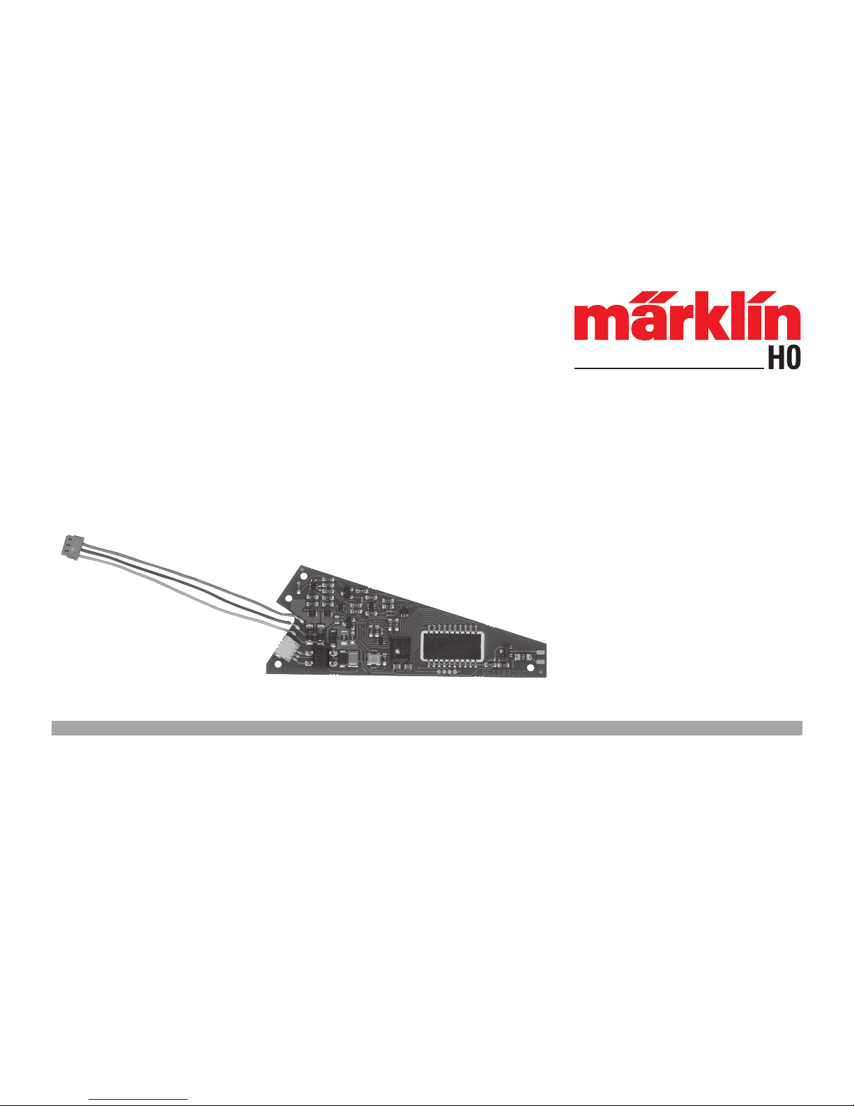
74462
Einbau-Digital-Decoder
Digital Installation Decoder
Décodeur numérique à installer
Inbouw-digitaaldecoder
Decoder digital integrable
Decoder Digital installabile
Dekodermontage
Digital indbygningsdekoder
Page 2

2
Inhaltsverzeichnis Seite
Bestimmungsgemäße Verwendung 4
Lieferumfang 4
Sicherheitshinweise 4
Wichtige Hinweise 4
Technische Daten 4
Funktionen 4
Decoder-Einbau 5/28
CV Programmierung 5
Betrieb unter mfx 6
Alternative Stromversorgung 30
Programmier-Tabellen 38
Sommaire Page
Usage conforme 10
Matériel fourni 10
Consignes de sécurité 10
Indications importantes 10
Caractéristiques techniques 10
Fonctions 10
Installation du décodeur 11/28
Programmation des CV 11
Exploitation sous mfx 12
Alimentation en courant alternative 32
Tableau de programmation 38
Table of Contents Page
Normal Use 7
Contents as Delivered 7
Safety Notes 7
Important Information 7
Technical Data 7
Functions 7
Decoder Installation 8/28
CV Programming 8
Operation with mfx 9
Alternative Power Supply 31
Programming Table 38
Inhoudsopgave Pagina
Beoogd gebruik 13
Leveringsomvang 13
Veiligheidsvoorschriften 13
Belangrijke aanwijzingen 13
Technische gegevens 13
Werking 13
Decoder inbouwen 14/28
CV-programmering 14
Bedrijf met mfx 15
Alternatieve stroomvoorziening 33
Programmeertabel 38
Page 3

3
Índice Página
Uso previsto 16
Alcance de suministro 16
Instrucciones de seguridad 16
Notas importantes 16
Datos técnicos 16
Funciones 16
Montaje del decoder 17/28
Programación de variables CV 17
Funcionamiento en modo mfx 18
Alimentazione di corrente alternativa 34
Tabla de programación 38
Innehållsförteckning Sidan
Användningsområde 22
Ingående material vid leverans 22
Säkerhetsanvisningar 22
Viktig information 22
Tekniska data 22
Funktioner 22
Inbyggnad av dekodern 23/28
CV programmering 23
Körning med mfx 24
Alternativ strömförsörjning 36
Programmeringstabell 38
Elenco del contenuto Pagina
Impiego commisurato alla destinazione 19
Corredo di fornitura 19
Avvertenze di sicurezza 19
Avvertenze importanti 19
Dati tecnici 19
Funzioni 19
Montaggio del Decoder 20/28
Programmazione delle CV 20
Esercizio sotto mfx 21
Alimentación eléctrica 35
Tabella di programmazione 38
Indholdsfortegnelse Side
Hensigtsmæssig anvendelse 25
Leveringsomfang 25
Sikkerhedsbemærkninger 25
Vigtige bemærkninger 25
Tekniske data 25
Funktioner 25
Indbygning af dekoder 26/28
CV programmering 26
Drift med mfx 27
Alternativ strømforsyning 37
Programmeringstabel 38
Page 4

4
Bestimmungsgemäße Verwendung
• Der Einbau-Digital-Decoder ist zum Einbau in Märklin- und
Trix-C-Gleis-Weichen mit Weichenantrieb bestimmt (ausgenommen Märklin-Dreiwegweiche).
• Der Einbau-Digital-Decoder darf bei externer Stromversorgung nur an Märklin- bzw. Trix-Schaltnetzteile angeschlossen
werden.
• Darf nur in trockenen Räumen verwendet werden.
Lieferumfang
1 Einbau-Digital-Decoder
1 Kabel gelb, rot und braun (C-Gleis Märklin)
1 Kabel blau, rot und weiß (C-Gleis Trix)
Einbauanleitung
Garantieurkunde
Für den Einbau zusätzlich benötigtes Werkzeug: Pinzette und Lötstation für eine Löttemperatur bis max. 30W/300˚mit dünner Spitze,
Elektronik-Lötzinn (Ø 0,5-1 mm), Entlötlitze oder Entlötsaugpumpe.
Sicherheitshinweise
• ACHTUNG! Funktionsbedingte scharfe Kanten und Spitzen.
• Verkabelungs- und Montagearbeiten nur im spannungslosen
Zustand ausführen. Bei Nichtbeachtung kann es zu gefährlichen Körperströmen und damit zu Verletzungen führen.
• Decoder nur mit der zulässigen Spannung (siehe technische
Daten) betreiben.
Beim Umgang mit dem Lötkolben besteht die Gefahr von
Hautverbrennungen.
Wichtige Hinweise
• Achtung: Beim Einbau möglichst keine Bauteile auf der
Oberseite des Einbau-Digital-Decoders berühren, statische
Aufladung kann die Funktion beeinträchtigen.
• Die Bedienungsanleitung ist Bestandteil des Produktes und
muss deshalb aufbewahrt sowie bei Weitergabe des Produktes mitgegeben werden.
• Für Reparaturen wenden Sie sich bitte an Ihren MärklinFachhändler.
• http://www.maerklin.com/en/imprint.html
Technische Daten
• Belastung Laternenausgang ≤ 100 mA
• Belastung Weichenausgang max. 2 A
• Spannung Digitalstromkreis max. 20 V eff.
• Spannung extern max. 20 V DC
• Spannungsfestigkeit max. 40 V
Funktionen
• Multiprotokoll fähig: fx (MM), mfx* und DCC
• Einstellen der Betriebsart mittels DIP-Schalter,
siehe Seite 38
• Einstellbare Adressen mit DIP-Schalter:
1-256 fx (MM) (Control Unit 6021 / Central Station 1)
1-320 fx (MM) (Central Station 2/3 / Mobile Station 2)
1-511 (DCC)
• Programmierbare Adressen über CV
1-2.044 DCC
• gültig ist die jeweils letzte Adresseinstellung, egal ob über
Programmierung oder über DIP-Schalter
• Änderungen der Eigenschaften über CV
* mfx erst ab CS 2 Softwareversion 4.0
Page 5

5
• Digitalsignal: Übertragung unabhängig von der Stromversorgung
• Stromversorgung über Digitalstromkreis
• Alternative Stromversorgung
• Lötpads für Anschluss der Weichenlaterne
• Weichenlaterne aus- oder einschaltbar
Decoder-Einbau
Folgende Arbeitsschritte dürfen nur im spannungslosen Zustand
ausgeführt werden:
• Stecken Sie das mitgelieferte Kabel (Gleissystem beachten)
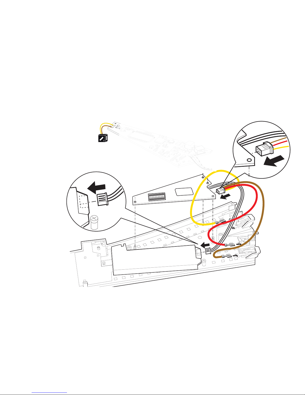
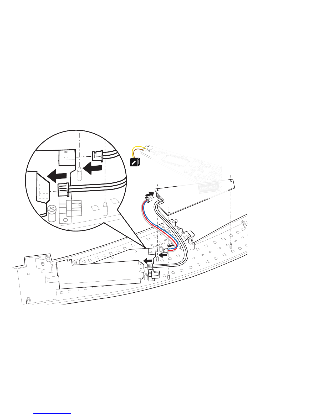
in die dafür vorgesehene Buchse, siehe Seite 28/29 (Märklin
und Trix). Folgen Sie nun der bebilderten Anleitung.
Änderungen der anderen Eigenschaften im fx (MM)-Protokoll
durch CV-Programmierung oder zur DCC CV-Programmierung
folgen Sie dem Kapitel „CV Programmierung“.
Beachten Sie: Einstellungen mit dem DIP-Schalter immer spannungslos vornehmen. Der Einbau-Digital-Decoder erkennt erst
mit dem Einschalten der Spannung die aktuellen Schalterstellungen.
Ab Seite 39 finden Sie die Tabelle für die Adressierung mit DIPSchalter.
Einbau des Einbau-Digital-Decoders in Märklin-Standard-,
Bogen- oder Doppelkreuzungsweiche siehe Seite 28.
Alternative Stromversorgung siehe Seite 30.
Einbau des Einbau-Digital-Decoders in Trix-Standard-, Bogen-
oder Doppelkreuzungsweiche siehe Seite 29.
Alternative Stromversorgung siehe Seite 30.
CV Programmierung
Die CV Programmierung muss am Programmiergleis erfolgen.
Für die Programmierung empfehlen wir, ist eine Lokomotive
manuell anzulegen. Werte in Klammern sind die Werkseinstellungen.
Während der Datenübertragung blinkt zur Kontrolle die am
Einbau-Digital-Decoder angeschlossene Weichenlaterne.
Die Programmierung kann wahlweise über fx (MM) oder DCC
erfolgen. Die Einstellung der Adresse empfehlen wir bei fx (MM)
mittels DIP-Schalter (siehe 39ff) durchzuführen.
fx (MM)
Vor der Programmierung muss die zu programmierende Weiche
mit dem Keyboard geschaltet werden. Danach unverzüglich mit
der Control Unit bzw. CV Konfiguration der Central Station die CV
ändern. Sofort danach die neu programmierte Weiche wieder
mit dem Keyboard schalten. Erst jetzt ist die Programmierung
übernommen und wirksam.
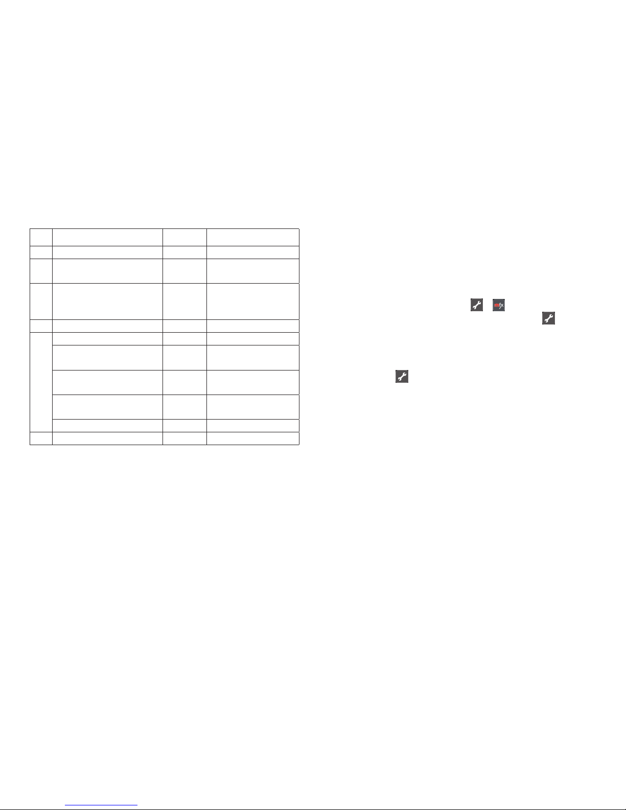
CV Bedeutung Werte
8 Decoder-Reset 8 (-) Werkseinstellung, Wert
wird nicht geschrieben
36 Weichenlaterne
aus/ein
0-1 (1) kann nur während der
Programmierung festgelegt
werden.
Die Vorgehensweise beim Programmieren mit der Control Unit
6021 entspricht der Lokprogrammierung (www.maerklin.de ->
Service -> Technische Informationen).
Page 6
6
DCC
CV Bedeutung Werte
1 Adresse, niederwertige
Byte
0-255 (1)
7 Hersteller Versionsnum-
mer (Softwareversion)
(-) nur lesen
8 Hersteller Kennung ID
Decoder Reset
(131)
8 (-)
nur lesen,
Werkseinstellung, Wert
wird nicht geschrieben
9 Adresse, höherwertige
Byte
0-7 (0)
29 Konfiguration (192) nur lesen
Bit 0-4 werden nicht
verwendet
0
Bit 5: Decodertyp 0 / 32 Basis- o. erweiterter
Zubehördecoder
Bit 6: Adressierungsmethode
0 / 64
Decoder- o. Aus-
gangsadresse
Bit 7: Decoderart 128 Zubehördecoder
36 Weichenlaterne, aus/ein 0-1 (1)
Einstellen und errechnen der Adressen größer 255:
Z.B. Adresse 1044 -> 1044:256=4,078125 . Der Wert vor dem
Komma (4) ist in CV 9 einzutragen. Den Wert nach dem Komma
(0,078125) wird mit 256 multipliziert 0,078125x256=20. Der errechnete Wert 20 muss in CV 1 eingetragen werden.
Betrieb unter mfx
Die mfx-Anmeldung kann unter MM oder DCC erfolgen.
Entscheidend ist die über den Dip-Schalter 10 eingestellte
Betriebsart.
Die mfx-Anmeldung wird mit der CS2 60213/60214/60215 in
der Magnetartikelkonfiguration über > und mit der CS3
60216/60226 in der Magnetartikelkonfiguration über
>„mfx-Artikel suchen“ angestoßen.
Hinweis zur mfx-Anmeldung mit der CS2:
Auswahlmöglichkeit „Magnetartikel automatisch zuweisen“
unter „Setup“ > > „Gleis“.
Ist dort das Häkchen gesetzt erfolgt die mfx-Anmeldung auf die
ersten freien Adressen in der CS2. Ist das Häkchen nicht gesetzt,
erfolgt die mfx-Anmeldung auf die tatsächlich am Decoder
programmierten Adressen.
Page 7

7
Normal Use
• This digital installation decoder is designed for installation in
Märklin and Trix C Track turnouts with a turnout mechanism
(exception: Märklin three-way turnout).
• This digital installation decoder may only be connected to
Märklin or Trix switched mode power packs for external
power supply.
• This decoder may only be used in dry areas indoors.
Contents as Delivered
1 digital installation decoder
1 cable – yellow, red, and brown (for Märklin C Track)
1 cable – blue, red, and white (for Trix C Track)
Installation instructions
Warranty card
Additional tools required for installation: tweezers and soldering
station for a maximum soldering temperature of 30 watts /
300˚ Celsius / 572˚ Fahrenheit with a fine point, Electronic solder
(0.5-1 mm dia.), desoldering braid or desoldering pump.
Safety Notes
• IMPORTANT! This product has sharp edges and points related
to its function.
• Do wiring and assembly work only in a voltage-free work
environment. Otherwise you may experience electrical current
dangerous to the body leading to injury.
• Operate this decoder only with the permissible voltage
(see technical information).
When using a solder station there is the danger of burning
your skin.
Important Information
• Important: When installing the digital installation decoder,
try to avoid touching components on the upper side of the
decoder. Static charge can affect the function of the decoder.
• The operating instructions are a component part of the
product and must therefore be kept with the product,
particularly when it is given to another party.
• For repairs please see your authorized Märklin specialty
dealer.
• http://www.maerklin.com/en/imprint.html
Technical Data
• Load at lantern output ≤ 100 milliamps
• Load at turnout output max. 2 amps
• Voltage for the digital power circuit max. 20 volts eff.
• External voltage max. 20 volts DC
• Electrical strength max. 40 volts
Functions
• Capable of multi-protocols: fx (MM), mfx* and DCC
• Setting the mode of operation by means of DIP switches, see
Page 38
• Addresses can be set with DIP switches:
1-256 fx (MM) (Control Unit 6021 / Central Station 1)
1-320 fx (MM) (Central Station 2/3 / Mobile Station 2)
1-511 (DCC)
• Programmable addresses using CVs
1-2,044 DCC
• The last respective address setting is valid, regardless of
whether it was done with programming or with the DIP
* mfx not until CS 2 Software Version 4.0
Page 8

8
switches
• Changes to characteristics can be done with CVs
• Digital signal: transfer independent of the power supply
• Power supply done using the digital power circuit
• Alternative power supply
• Solder pads for connections for turnout lanterns
• Turnout lanterns can be turned on or off
Decoder Installation
The following work steps may only be done in a voltage-free
work environment:
• Plug the cable included with the decoder (pay attention to the
track system) in the socket provided for it – see page 28/29
(Märklin and Trix). Now follow the illustrated instructions.
See the section “CV Programming” for changes to other characteristics in the fx (MM) protocol using CV programming or to
the DCC CV programming.
Note: Settings with the DIP switches are to be only when the
voltage is turned off. The digital installation decoder does not recognize the current switch settings until the voltage is turned on.
Starting on page 39 you’ll find the table for setting addresses
with DIP switches.
See page 28 for installation of the digital installation decoder
in Märklin standard turnouts, curved turnouts, or double slip
switches.
Alternative Power Supply page 31
See page 29 for installation of the digital installation decoder in
Trix standard turnouts, curved turnouts, or double slip switches.
Alternative Power Supply page 31
CV Programming
CV programming must be done on the programming track.
We recommend creating a fictitious locomotive for programming
purposes. Values in parentheses are the factory settings.
The turnout lantern connected to the digital installation decoder
will blink as a control check during the data transmission.
The programming can be done optionally with fx (MM) or DCC.
In fx (MM), we recommend setting the address by means of DIP
switches (see 39ff).
fx (MM)
Before doing any programming, the turnout to be programmed
must be switched with the Keyboard. After that the CVs are
changed immediately with the Control Unit or the CV configuration on the Central Station. Immediately after that, switch the
newly programmed turnout again with the Keyboard. At this
point the programming is accepted and is functional.
CV Meaning Values
8 Decoder reset 8 (-) factory setting, not written
value is
36 Turnout lantern
off/on
0-1 (1)
The procedure for programming with the 6021 Control Unit is the
same as locomotive programming (www.maerklin.de -> Service
-> Technische Informationen).
Page 9
9
DCC
CV Meaning Values
1 Address, lower value
Byte
0-255 (1)
7 Manufacturer version
number (software
version)
(-) read only
8 Manufacture recognition
ID Decoder reset
(131)
8 (-)
read only,
factory setting, value
is not written
9 Address, higher value
Byte
0-7 (0)
29 Configuration (192) read only
Bits 0-4 are not used 0
Bit 5: Decoder type 0 / 32 basic or advanced
accessory decoder
Bit 6: Addressing method
0 / 64
decoder or output
address
Bit 7: Decoder type 128 accessory decoder
36 Turnout lantern, off/on 0-1 (1)
Setting and generating addresses larger than 255:
Example: Address 1044 -> 1044:256=4,078125 . The value before
the comma (4) is to be entered in CV 9. The value after the comma (0,078125) is multiplied by 256, 078125x256=20. The value of 20
that is generated must be entered in CV 1.
Operation with mfx
mfx registration can be done with MM or DCC.The mode of operation that has been set by means of Dip Switch 10 is critical.
The mfx registration is initiated with the 60213/60214/60215 CS2
in > and with the 60216/60226 CS3 in the solenoid item
configuration by means of >“search for mfx item“.
Note about mfx registration with the CS2:
Selection possibility „Automatically assign solenoid item“ at
„Setup“ > > „Track“.
If the check mark there is checked, the mfx registration is done
at the first open address in the CS2. If the check mark is not
checked, the mfx registration is done at the address actually
programmed on the decoder.
Page 10

10
Usage conforme
• Le décodeur numérique est conçu pour être installé dans des
aiguilles de voie C Märklin et Trix équipées d‘un moteur (à
l‘exception des aiguillages triple Märklin).
• Dans le cas d’une alimentation en courant externe, ce
décodeur numérique peut être raccordé uniquement à un
convertisseur continu-continu Märklin ou Trix.
• A utiliser exclusivement dans des pièces sèches.
Matériel fourni
1 Décodeur numérique à installer
1 câble de chaque couleur suivante : jaune, rouge et marron
(voie C Märklin)
1 câble de chaque couleur suivante : bleu, rouge et blanc
(voie C Trix)
Notice d’installation
Bon de garantie
Outils nécessaires à l’installation : Pincette et poste à ouder
pour une température de brasage maximale de 30 W/300˚avec
pointe fine, fil à souder pour électronique (Ø 0,5-1 mm), tresse à
dessouder ou pompe à dessouder.
Consignes de sécurité
• ATTENTION ! L’appareil présente des arêtes coupantes.
• Câblage et montage doivent être réalisés uniquement quand
l’appareil est hors tension. Le non respect de ces consignes
peut générer des courants de choc dangereux et être à
l’origine de blessures.
• Exploiter le décodeur uniquement avec la tension autorisée
(voir caractéristiques techniques).
Risques de brûlures lors de la manipulation du fer à souder.
Indications importantes
• Attention : Lors de l’installation, éviter dans la mesure du
possible de toucher les composants situés sur la face supérieure du décodeur numérique, une charge statique pouvant
entraver le fonctionnement.
• La notice d‘utilisation fait partie intégrante du produit ; elle
doit donc être conservée et, le cas échéant, transmise avec
le produit.
• Pour toute réparation, adressez-vous SVP à votre détaillant
spécialisé Märklin.
• http://www.maerklin.com/en/imprint.html
Caractéristiques techniques
• Charge sortie lanterne ≤ 100 mA
• Charge sortie aiguille max. 2 A
• Tension circuit numérique max. 20 V eff.
• Tension externe max. 20 V c.c.
• Tenue en tension max. 40V
Fonctions
• multi protocole: fx (MM), mfx* et DCC
• Définition du mode d’exploitation via commutateur DIP, voir
page 38
• Définition des adresses possible via commutateur DIP :
1-256 fx (MM) (Control Unit 6021 / Central Station 1)
1-320 fx (MM) (Central Station 2/3 / Mobile Station 2)
1-511 (DCC)
• Adresses programmables via CV
1-2 044 DCC
• C’est toujours la dernière adresse enregistrée qui prévaut,
* mfx à partir de la version logicielle CS 2 4.0
Page 11

11
qu’elle ait été programmée ou définie via commutateur DIP
• Modifications des propriétés via CV
• Signal numérique : Transmission indépendante de l’alimentation en courant
• Alimentation en courant via circuit numérique
• Alimentation en courant alternative
• Plages d’accueil pour raccordement de la lanterne d’aiguille
• Lanterne d’aiguille commutable
Installation du décodeur
L’installation, dont les différentes étapes sont décrites
ci- dessous, doit impérativement être réalisée hors tension :
• Enfichez le câble fourni (tenir compte du système de voie)
dans la prise prévue à cet effet, voir page 28/29 (Märklin et
Trix). Suivez alors la notice illustrée.
Pour modifier les autres caractéristiques dans le protocole
fx (MM) via la programmation des CV ou pour la programmation
des CV dans le protocole DCC, veuillez suivre les indications du
chapitre « Programmation des CV ».
Attention : Les paramétrages avec le commutateur DIP doivent
toujours se faire hors tension. Le décodeur numérique ne
reconnaît les nouvelles positions du commutateur qu’à la mise
sous tension.
Vous trouverez le tableau pour la définition des adresses avec
commutateur DIP à partir de la page 39.
Installation du décodeur numérique dans les aiguillages
standard, enroulés ou traversées de jonction double Märklin :
voir page 28.
Alimentation en courant alternative voir page 32.
Installation du décodeur numérique dans les aiguillages
standard, enroulés ou traversées de jonction double Trix :
voir page 29.
Alimentation en courant alternative voir page 32.
Programmation des CV
La programmation des CV se fait sur la voie de programmation.
Pour la programmation, nous vous conseillons de créer une
locomotive fictive. Les valeurs indiquées entre parenthèses
correspondent aux paramètres d‘usine.
Durant la transmission des données, la lanterne d’aiguille
raccordée au décodeur numérique clignote (contrôle).
La programmation peut se faire au choix via fx (MM) ou DCC.
Pour fx (MM), nous conseillons de définir l’adresse via commutateur DIP (voir page 39 et suivantes).
fx (MM)
Avant de procéder à la programmation, commutez l’aiguille à
programmer via le Keyboard. Modifiez ensuite sans attendre la
CV avec la Control Unit, respectivement via la fonction de configuration des CV de la Central Station. Commutez alors à nouveau
et immédiatement l’aiguille programmée via le Keyboard. La
programmation est enfin enregistrée et effective.
CV Signification Valeurs
8 Réinitialisation du
décodeur
8 (-) Paramètre d’usine, la va-
leur n’est pas enregistrée
36 Lanterne d’aiguille
allumée/éteinte
0-1 (1)
Page 12
12
La procédure à suivre pour la programmation avec la
Central Unit 6021 correspond à la programmation de la loco
(www.maerklin.de -> Service -> Technische Informationen)
DCC
CV Signification Valeurs
1 Adresse, octet de valeur
basse
0-255 (1)
7 Numéro de version fabri-
cant (version logicielle)
(-) Lire uniquement
8 Identifiant du fabricant
Réinitialisation du
décodeur
(131)
8 (-)
Lire uniquement,
paramètre d’usine,
la valeur n’est pas
enregistrée
9 Adresse, octet de valeur
supérieure
0-7 (0)
29 Configuration (192) Lire uniquement
Bits 0 à 4 non utilisés 0
Bit 5: Type de décodeur 0 / 32 Décodeur
d‘accessoires de
base ou avancé
Bit 6: Méthode
d’adressage
0 / 64
Adresse du décodeur
ou adresse de départ
Bit 7: Type de décodeur 128 Décodeur
d’accessoires
36 Lanterne d’aiguille
allumée/éteinte
0-1 (1)
Définition et calcul des adresses supérieures à 255 :
Par ex. Adresse 1044 -> 1044:256=4,078125 . La valeur avant la
virgule (4) est à reporter dans la CV 9. La valeur située après
la virgule (0,078125) est multipliée par 256 0,078125x256=20.
La valeur calculée 20 est à reporter dans la CV 1.
Exploitation sous mfx
L’enregistrement mfx peut se faire sous MM ou DCC.
C‘est le mode d’exploitation défini via le commutateur Dip 10 qui
importe ici.
Avec la CS2 60213/60214/60215, l’enregistrement mfx est lancé
dans la configuration des articles électromagnétiques via >
et avec la CS3 60216/60226 dans la configuration des articles
électromagnétiques via >„Rechercher articles mfx“.
Remarque concernant la connexion mfx avec la CS2 :
Sélection possible „Affectation automatique d’un article électromagnétique“ sous „Configuration“ > > „Voie“.
Si cette possibilité est cochée, l’enregistrement mfx se fait sur
les premières adresses libres dans la CS2. Si cette possibilité
n’est pas cochée, l’enregistrement mfx se fait sur les adresses
réellement programmées sur le décodeur.
Page 13

13
Beoogd gebruik
• De inbouw-digitaaldecoder is bedoeld voor het inbouwen in
Märklin- en Trix C-rail wissels met wisselaandrijving (uitgezonderd de Märklin driewegwissel).
• De inbouw-digitaaldecoder mag bij het gebruik van een
externe voeding alleen aan een Märklin of Trix netadapter
aangesloten worden.
• Mag alleen in droge ruimtes gebruikt worden.
Leveringsomvang
1 inbouw-digitaaldecoder
1 kabel geel, rood en bruin (C-rail Märklin)
1 kabel blauw, rood en wit (C-rail Trix)
Gebruiksaanwijzing
Garantiebewijs
Voor het inbouwen is het volgende gereedschap nodig: pincet en
soldeerstation met een maximale temperatuur van 30W/300 0C
met een dunne stift, elektronica soldeertin (0.5 - 1mm), desoldeerlitze of soldeertinzuiger.
Veiligheidsvoorschriften
• Let op! bevat vanwege zijn functie scherpe randen en punten.
• bedrading- en montage alleen in spanningloze toestand uitvoeren. Bij het niet naleven kunnen er gevaarlijke stromen door het
lichaam vloeien en verwondingen ontstaan.
• Decoder alleen met de toegelaten spanning (zie technische
gegevens) gebruiken.
Bij het werken met een soldeerbout bestaat het gevaar voor
brandwonden.
Belangrijke aanwijzingen
• Let op: bij het inbouwen de delen op de bovenzijde van de
inbouw-digitaaldecoder niet aanraken, statische ontlading
kan de juiste werking be invloeden.
• De gebruiksaanwijzing is onderdeel van het product en moet
derhalve bij de overdracht van het product meegegeven
worden.
• Voor reparaties kunt u zich tot uw Märklin dealer wenden.
• http://www.maerklin.com/en/imprint.hmtl
Technische gegevens
• Belasting lantaarnuitgang <100mA
• Belasting wisseluitgang max. 2A
• Spanning digitale stroomkring max. 20 V eff.
• Spanning extern max. 20 V DC
• Diëlektrische sterkte max. 40 V
Werking
• Multiprotocol: fx (MM), mfx* en DCC
• Instellen van de bedrijfssoort met de dipschakelaars,
zie pag. 38
• Instellen van het adres met DIP-schakelaar
1-256 fx (MM) (Control Unit 6021 / Central Station 1)
1-320 fx (MM) (Central Station 2/3 / Mobile Station 2)
1-511 (DCC)
• Programeerbare adressen via CV
1-2044 DCC
• De laatst ingestelde adresinstelling is geldig, ongeacht of
deze geprogrammeerd of met de dipschakelaars is ingesteld.
• Wijzigen van de eigenschappen via CV
* mfx pas vanaf CS 2 softwareversie 4.0
Page 14

14
• Digitaal signaal: overdracht onafhankelijk van de stroomvoorziening.
• Stroomvoorziening via digitale stroomkring
• Alternatieve stroomvoorziening
• Soldeervelden voor het aansluiten van de wissellantaarn
• Wissellantaarn uit- en inschakelbaar
Decoder inbouwen
De volgende stappen mogen alleen in spanningloze toestand
uitgevoerd worden:
• Steek de stekker van meegeleverde kabel (let op het railsysteem) in de daarvoor bestemde stekkerbus, zie pagina 28/29
(Märklin en Trix). Volg de afgebeelde aanwijzingen.
Veranderen van de te wijzigende eigenschappen in het fx (MM)
protocol door CV programmering of het DCC CV programmering
vindt u in het hoofdstuk “CV programmering”.
Let op: instellingen van de DIP-schakelaars alleen in spanningloze toestand uitvoeren. De inbouw-digitaaldecoder herkend
de actuele schakelaarstand pas na het inschakelen van de
voedingsspanning.
Vanaf pagina 39 vindt u de tabel voor de adressering met de
DIP-schakelaars.
Inbouw van de inbouw-digitaaldecoder in de Märklin standaardmeegebogen- en kruiswissels zie pagina 28.
Alternatieve stroomvoorziening zie pagina 33.
Inbouw van de inbouw-digitaaldecoder in de Trix standaard-
meegebogen- en kruiswissels zie pagina 29.
Alternatieve stroomvoorziening zie pagina 33.
CV Programmering
De CV programmering moet via het programmeerspoor gebeuren. Voor het programmeren is het aan te bevelen een fictive
loc aan te maken. De waarden tussen haakjes zijn de af fabriek
ingestelde waarden.
Tijdens de dataoverdracht knippert, ter controle, de aan de
inbouw-digitaaldecoder aangesloten wisselantaarn.
De programmering kan naar wens via fx (MM) of DCC uitgevoerd
worden. We adviseren de adresinstelling bij fx (MM) m.b.v. de
dipschakelaars (zie pag. 39) uit te voeren.
fx (MM)
Voor het programmeren moet de te programmeren wissel met
het keyboard geschakeld worden. Daarna onmiddellijk met de
Control Unit resp. via CV configuratie met het Central Station de
CV wijzigen. Direct daarna de opnieuw geprogrammeerde wissel
weer met het keyboard schakelen. Pas dan is de programmering
overgenomen en werkzaam.
CV Omschrijving Waarde
8 Decoder reset 8 (-) Fabrieksinstelling, waarde
wordt niet geschreven
36 Wissellantaarn
uit/aan
0-1 (1)
De werkwijze bij het programmeren met de Control Unit 6021
komt overeen met het programmeren van een locomotiefdecoder (www.maerklin.de -> Service -> Technische Informationen).
Page 15
15
DCC
CV Omschrijving Waarde
1 Adres, lage byte 0-255 (1)
7 Fabrikant versienummer
(softwareversie)
(-) alleen lezen
8 Fabrikant kenmerk ID
decoder reset
(131)
8 (-)
alleen lezen, fabrieksinstelling, waarde
wordt niet geschreven
9 Adres, hoge byte 0-7 (0)
29 Configuratie (192) alleen lezen
Bit 0-4 worden niet
gebruikt
0
Bit 5: decodertype 0 / 32 Basis- of uitgebreide
toebehoren decoder
Bit 6: adresseringsmethode
0 / 64
Decoder of uitgangs-
adres
Bit 7: decodertype 128 Toebehoren decoder
36 Wissellantaarn uit/aan 0-1 (1)
Instellen en berekenen van de adressen groter dan 255:
Bijv. adres 1044 -> 1044:256=4,078125. De waarde voor de komma
(4) moet in CV 9 ingevoerd worden. De waarde achter de komma
(0,078125) wordt nu met 256 vermenigvuldigd 0,078125x256=20.
De berekende waarde 20 moet in CV 1 ingevoerd worden.
Bedrijf met mfx
De mfx aanmelding kan zowel onder MM als onder DCC
gebeuren.
Bepalend daarvoor is het ingestelde bedrijfstype met dipschakelaar 10.
De mfx aanmelding wordt met het CS2 60213/60214/60215 in
de magneetartikel configuratie via > en met het CS3
60216/60226 in de magneetartikelen configuratie via > “mfxartikel zoeken” gestart.
Opmerking t.a.v. mfx aanmelding met het CS2
Keuzemogelijkheid “Magneetartikelen automatisch toewijzen”
onder “Setup” > “Rail”.
Als daar het vinkje gezet is, vindt de mfx-aanmelding plaats
op de eerste vrije adressen in het CS2. Is het vinkje niet gezet,
dan vindt de mfx-aanmelding op het werkelijke, op de decoder
geprogrammeerde adres plaats.
Page 16

16
Uso previsto
• El decoder digital integrable está destinado para el montaje
en desvíos para vías C de Märklin y Trix con accionamiento
de aguja (con excepción del desvío de tres itinerarios de
Märklin).
• Está permitido conectar el decoder digital integrable, en
el caso de alimentación externa, únicamente a fuentes de
alimentación conmutadas de Märklin o de Trix.
• Su uso está permitido únicamente en recintos secos.
Alcance de suministro
1 decoder digital integrable
1 cable amarillo, rojo y marrón (vía C de Märklin)
1 cable azul, rojo y blanco (vía C de Trix)
Instrucciones de montaje
Documento de garantía
Herramienta adicional necesaria para el montaje: Pinza y
estación de soldadura para una temperatura de soldeo de máx.
30W/300˚ con punta fina, estaño de soldar para electrónica (Ø
0,5-1 mm), cordón de desoldeo o bomba aspiradora de desoldeo.
Instrucciones de seguridad
• ¡ATENCIÓN! El diseño presenta aristas y puntas cortantes
impuestas por las características funcionales.
• Ejecutar los trabajos de cableado y montaje únicamente
sin tensión. En el caso de inobservancia pueden producirse
corrientes peligrosas a través del cuerpo y, por tanto, lesiones.
• Utilizar el decoder únicamente con la tensión admisible
(véase Datos técnicos).
Al manejar el soldador pueden producirse quemaduras
de la piel.
Notas importantes
• Atención: En el montaje, a ser posible, no tocar componentes
situados en el lado superior del decoder digital integrable ya
que las cargas estáticas pueden perjudicar a su funcionamiento.
• Las instrucciones de empleo forman parte integrante del
producto y, por este motivo, deben conservarse y entregarse
al nuevo comprador en el caso de venta del mismo.
• Para reparaciones, por favor diríjase a su distribuidor
especializado de Märklin.
• http://www.maerklin.com/en/imprint.html
Datos técnicos
• Carga por salida de farol ≤ 100 mA
• Carga por salida de desvío max. 2 A
• Tensión de circuito digital máx. 20 V efi.
• Tensión externa máx. 20 V DC
• Rigidez dieléctrica máx. 40 V
Funciones
• Apto para múltiples protocolos: fx (MM), mfx* y DCC
• Configuración del modo de funcionamiento mediante microinterruptores DIP, véase página 38
• Direcciones configurables mediante interruptor DIP:
1-256 fx (MM) (Control Unit 6021 / Central Station 1)
1-320 fx (MM) (Central Station 2/3 / Mobile Station 2)
1-511 (DCC)
• Direcciones programables mediante variables CV
1-2.044 DCC
• la dirección válida es la última dirección configurada, ya sea
mediante programación o mediante microinterruptores DIP
* mfx no está disponible hasta la versión de software 4.0 de la CS 2
Page 17

17
• Modificación de las características mediante variables CV
• Señal digital: Transmisión independiente de la alimentación
eléctrica
• Alimentación eléctrica mediante circuito digital.
• Alimentación eléctrica alternativa
• Terminales de soldadura para conexión de farol de aguja
• Farol de aguja activable o desactivable
Montaje del decoder
Está permitido ejecutar las siguientes operaciones únicamente
sin tensión.
• Enchufe el cable incluido (tener presente el sistema de vías)
en el conector hembra para ello previsto, véase página 28/29
(Märklin y Trix). Siga ahora las instrucciones ilustradas.
En el capítulo “Programación de las CVs” se explican las modificaciones de las demás características en el protocolo fx (MM)
mediante programaciones de variables CV o para la programación de variables CV en el protocolo DCC.
Nota importante: Realizar los ajustes con el microinterruptor
DIP siempre sin tensión. El decoder digital integrable no reconoce las posiciones actuales de los microinterruptores hasta que
no se enciende la alimentación eléctrica.
A partir de la página 39 encontrará la tabla para el direccionamiento con microinterruptores DIP.
Para el montaje del decoder digital integrable en un desvío
estándar, un desvío en curvas o una travesía de unión doble de
Märklin, véase página 28.
Alimentazione di corrente alternativa véase página 34.
Para el montaje del decoder digital integrable en un desvío
estándar, un desvío en curvas o una travesía de unión doble de
Trix, véase página 29.
Alimentazione di corrente alternativa véase página 34.
Programación de variables CV
La programación de variables CV debe realizarse en la vía de
programación. Para la programación recomendamos crear una
locomotora ficticia. Los valores entre paréntesis representan la
configuración de fábrica.
Durante la transmisión de datos, para comprobación, destella el
farol de aguja conectado al decoder digital integrable.
La programación se puede realizar opcionalmente vía fx (MM)
o DCC. Recomendamos configurar la dirección en el caso de
fx (MM) mediante microinterruptores DIP (véase página 39 y
siguientes).
fx (MM)
Antes de la programación, debe conmutarse con el Keyboard el
desvío que se desee programar. Inmediatamente después debe
modificarse la CV con la Control Unit o bien con la función Configuración de CV de la Central Station. Acto seguido, maniobrar
de nuevo con el keyboard el desvío recién programado. Hasta
que esto no se haya hecho no se aplicará ni tendrá efecto la
programación.
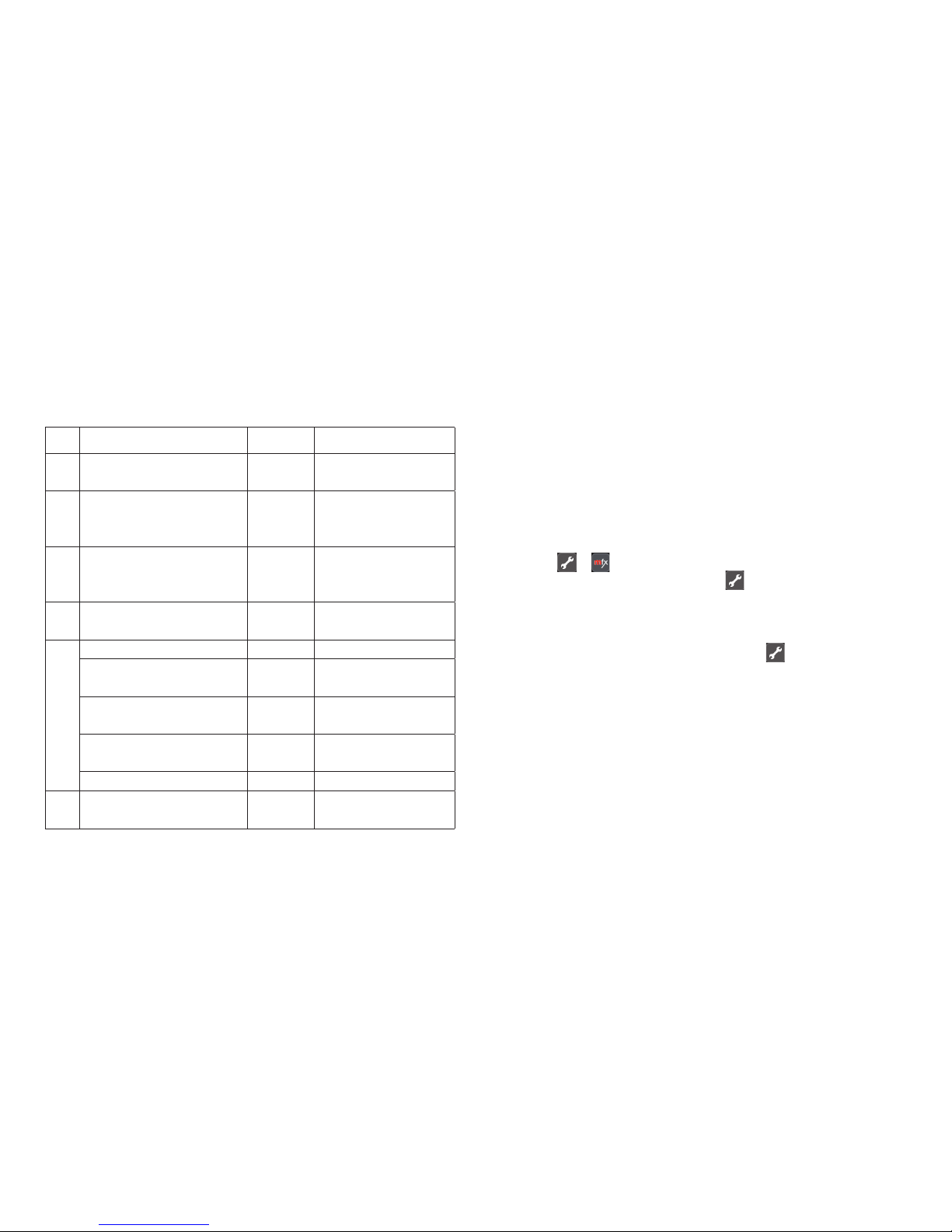
CV Significado Valores
8 Reset de decoder 8 (-) Configuración de fábrica,
no se escribe el valor
36 Apagar/encender
farol de aguja
0-1 (1)
Page 18
18
El procedimiento en la programación con la Central Unit equivale
a la programación de locomotora (www.maerklin.de -> Service
-> Technische Informationen).
DCC
CV Significado Valores
1 Dirección, byte de menor
peso
0-255 (1)
7 Número de versión de
fabricante (versión de
software)
(-) Sólo lectura
8 ID ident. de fabricante
Reset de decoder
(131)
8 (-)
Sólo lectura, configuración de fábrica, no
se escribe el valor
9 Dirección, byte de mayor
peso
0-7 (0)
29 Configuración (192) Sólo lectura
Bit 0-4 No se utilizan
los bits
0
Bit 5: Modelo de decoder 0 / 32 Decoder accesorio
básico o ampliado
Bit 6: Método de
direccionamiento
0 / 64
Dirección de
decoder o inicial
Bit 7: Tipo de decoder 128 Decoder accesorio
36 Desactivar/activar farol
de desvío
0-1 (1)
Configuración y cálculo de las direcciones mayores que 255:
P. ej., dirección 1044 -> 1044:256=4,078125. El valor antes de la
coma (4) debe registrarse en la CV 9. El valor después de la
coma (0,078125) se multiplica por 256 0,078125x256=20. El valor
calculado 20 debe registrarse en CV 1.
Funcionamiento en modo mfx
El inicio de sesión en mfx se puede realizar en modo MM o DCC.
El modo de funcionamiento se selecciona con el microinterruptor DIP 10.
El inicio de sesión en modo mfx se inicia con la CS2
60213/60214/60215 en la configuración de artículos magnéticos a
través de > y con la CS3 60216/60226 en la configuración
de artículos magnéticos a través de >“Buscar artículos mfx“.
Nota sobre el inicio de sesión en mfx con la CS2:
Posibilidad de selección de „Asignar automáticamente artículos
magnéticos“ en „Setup (configuración)“ > > „Vía“.
Si en estas funciones se ha activado la marca de verificación,
el inicio de sesión en modo mfx se realiza en las primeras
direcciones libres de la CS2. Si no está activada la marca de verificación, el inicio de sesión en mfx se realiza en las direcciones
realmente programadas en el decoder.
Page 19

19
Impiego commisurato alla destinazione
• Tale Decoder Digital installabile è destinato al montaggio
nei deviatoi del binario Märklin e Trix C con azionamento per
deviatoi (ad eccezione dei deviatoi a tre vie Märklin).
• Tale Decoder Digital installabile in caso di un’alimentazione
di corrente esterna deve venire collegato solamente ad
alimentatori «switching» da rete Märklin o rispettivam. Trix.
• Deve essere impiegato solamente in luoghi asciutti.
Corredo di fornitura
1 Decoder Digital installabile
1 cavetto giallo, rosso e marrone (binario Märklin C)
1 cavetto blu, rosso e bianco (binario Trix C)
Istruzioni di montaggio
Certificato di garanzia
Attrezzi necessari in aggiunta per il montaggio: una pinzetta e
una stazione di saldatura per una temperatura di saldatura sino
a un max. di 30W/300˚ con una punta sottile, lega per saldature
elettroniche (Ø 0,5-1 mm), trecciola dissaldante oppure pompetta
aspirante per dissaldare.
Avvertenze di sicurezza
• ATTENZIONE! Spigoli e punte affilati per necessità funzionale.
• Si eseguano i lavori di cablaggio e di montaggio solo in condizioni esenti da tensione. In caso di mancato rispetto questo
può condurre a pericolose correnti nel corpo e di conseguenza
a ferimenti.
• Si faccia funzionare il Decoder solamente con la tensione
ammissibile (si vedano i dati tecnici).
Durante le operazioni con il saldatore sussiste il pericolo di
scottature della pelle.
Avvertenze importanti
• Attenzione: durante il montaggio si tocchino il meno possibile
i componenti sul lato superiore del Decoder Digital installabile, le cariche statiche possono compromettere la funzionalità.
• Le istruzioni di impiego costituiscono parte integrante del prodotto e devono pertanto venire conservate con cura nonché
consegnate insieme in caso di cessione a terzi del prodotto.
• Per riparazioni Vi preghiamo di rivolgerVi al Vostro rivenditore
specialista Märklin.
• http://www.maerklin.com/en/imprint.html
Dati tecnici
• Carico dell’uscita per lanterne ≤ 100 mA
• Carico dell’uscita per deviatoi max. 2 A
• Tensione nel circuito di corrente Digital max. 20 V eff.
• Tensione esterna max. 20 V DC
• Rigidità dielettrica max. 40 V
Funzioni
• Capacità multi-protocollo: fx (MM), mfx* und DCC
• Impostazione del tipo di funzionamento per mezzo dei commutatori DIP, si veda pagina 38
• Indirizzi impostabili con commutatori DIP:
1-256 fx (MM) (Control Unit 6021 / Central Station 1)
1-320 fx (MM) (Central Station 2/3 / Mobile Station 2)
1-511 (DCC)
• Indirizzi programmabili tramite CV
1-2.044 DCC
• Valevole è rispettivamente l’ultima impostazione di indirizzo,
ugualmente se tramite programmazione oppure tramite
commutatori DIP.
* mfx solo a partire da CS 2 con Software versione 4.0
Page 20

20
• Modificazione delle caratteristiche tramite CV
• Segnale Digital: trasmissione indipendente dall’alimentazione
di corrente
• Alimentazione di corrente tramite circuito di corrente Digital
• Alimentazione di corrente alternativa
• Piazzole da saldare per collegamento della lanterna da
deviatoi
• Lanterna da deviatoi disattivabile o attivabile
Montaggio del Decoder
I seguenti passaggi del lavoro devono essere eseguiti solamente in condizioni esenti da tensione.
• Innestate il cavetto fornito in dotazione (si presti attenzione
al sistema dei binari) nella presa predisposta a tale scopo,
si veda a pagina 28/29 (Märklin e Trix). Seguite adesso le
istruzioni illustrate.
Per modificazioni delle altre caratteristiche nel protocollo fx
(MM) mediante programmazione delle CV oppure per programmazione delle CV in DCC seguite il capitolo «Programmazione
delle CV.»
Prestate attenzione: si intraprendano le impostazioni con il
commutatore DIP sempre senza tensione. Il Decoder Digital
installabile riconosce le attuali disposizioni del commutatore
solo con l’attivazione della tensione.
A partire da pagina 39 potete trovare la tabella per
l’indirizzamento con il commutatore DIP.
Per il montaggio del Decoder Digital installabile in deviatoi
Märklin normali, curvi oppure deviatoi inglesi doppi si veda a
pagina 28.
Alimentación eléctrica si veda a pagina 35.
Per il montaggio del Decoder Digital installabile in deviatoi Trix
normali, curvi oppure deviatoi inglesi doppi si veda a pagina 29.
Alimentación eléctrica de si veda a pagina 35.
Programmazione delle CV
La programmazione delle CV deve avvenire sul binario di
programmazione. Per tale programmazione noi consigliamo di
inserire una locomotiva immaginaria. I valori tra parentesi sono
le impostazioni di fabbrica.
Durante la trasmissione dei dati lampeggia per controllo la
lanterna da deviatoi collegata al Decoder Digital installabile.
La programmazione può avvenire a scelta mediante fx (MM)
oppure DCC. In caso di fx (MM) noi consigliamo di eseguire
l’impostazione dell’indirizzo per mezzo dei commutatori DIP (si
veda 39 e seg.).
fx (MM)
Prima della programmazione il deviatoio da programmare deve
venire commutato con la Keyboard. Dopo di ciò le CV vengono
immediatamente modificate con la Control Unit o rispettivamente
la configurazione CV della Central Station. Direttamente dopo,
commutare nuovamente con la Keyboard i deviatoi appena
programmati. Soltanto ora la programmazione è acquisita ed
operativa.
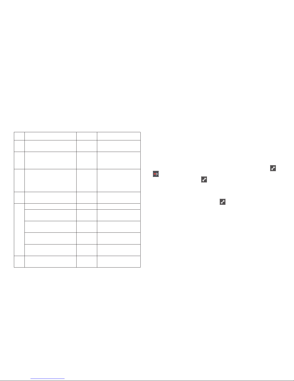
CV Significato Valori
8 Ripristino Decoder 8 (-) Impostazioni di fabbrica, il
valore non viene scritto
36 Lanterna da devia-
toi spenta/accesa
0-1 (1)
Page 21
21
Il modo operativo nella programmazione con la Central Unit 6021
corrisponde alla programmazione della locomotive
(www.maerklin.de -> Service -> Technische Informationen).
DCC
CV Significato Valori
1 Indirizzo, byte di valore
più basso
0-255 (1)
7 Numero di versione del
fabbricante (Versione
Software)
(-) sola lettura
8 ID identificativo del
fabbricante
Ripristino Decoder
(131)
8 (-)
sola lettura,
Impostazioni di
fabbrica, il valore non
viene scritto
9 Indirizzo, byte di valore
più alto
0-7 (0)
29 Configurazione (192) sola lettura
I bit 0-4 non vengono
usati
0
Bit 5: tipo di Decoder 0 / 32 Decoder per acces-
sori di base o esteso
Bit 6: metodo di indirizzamento
0 / 64
Indirizzo Decoder
o di uscita
Bit 7: tipo di Decoder 128 Decoder per
accessori
36 Lanterna da deviatoi
spenta/accesa
0-1 (1)
Impostazione e calcolo degli indirizzi maggiori di 255:
Ad es. indirizzo 1044 -> 1044:256=4,078125 . Il valore prima della
virgola (4) si deve inserire in CV 9. Il valore dopo la virgola
(0,078125) viene moltiplicato per 256: 0,078125x256=20. Il valore
calcolato 20 deve venire inserito in CV 1.
Esercizio sotto mfx
La registrazione mfx può avvenire sotto MM oppure DCC.
È discriminante il tipo di funzionamento impostato tramite il
commutatore Dip 10.
La registrazione mfx viene avviata con la CS2 60213/60214/60215
nella configurazione degli apparati elettromagnetici tramite >
e con la CS3 60216/60226 nella configurazione degli apparati
elettromagnetici tramite >„ricerca apparati mfx“.
Avvertenza sull’iscrizione mfx con la CS2:
Possibilità di selezione „Assegnare automaticamente apparati
elettromagnetici“ sotto „Setup“ > > „Binario“.
Se colà è posto il segno di spunta la registrazione mfx avviene
sul primo indirizzo libero nella CS2. Se il segno di spunta non è
collocato, la registrazione mfx avviene sull’indirizzo effettivamente programmato sul Decoder.
Page 22

22
Användningsområde
• Inbyggnadsdekodern är avsedd för att byggas in i Märklinoch Trix-C-växlar med växelmotorer (undantaget Märklins
trevägsväxlar).
• Inbyggnadsdekodern får vid extern strömförsörjning endast
anslutas till Märklins eller Trix nätenhet.
• Den får endast användas i torra rum och utrymmen.
Ingående material vid leverans
1 inbyggnadsdekoder
1 gul, röd och brun kabel (Märklin C-räls)
1 blå, röd och vit kabel (Trix-C-räls)
Inbyggnadsanvisningar
Garantisedel
För inbyggnaden fordras följande verktyg: Pincett och lödstation
med tunn lödspets för en lödtemperatur av 30W/300°, elektroniklödtenn (Ø 0,5 - 1 mm), avlödningsfläta eller tennsug.
Säkerhetsanvisningar
• VARNING! Funktionsbetingade skarpa kanter och spetsiga
delar.
• Anslutning av kablar och montagearbeten får endast göras i
spänningslöst tillstånd. Om dessa anvisningar ej följs kan det
leda till farliga strömmar och strömstyrkor som kan åsamka
kroppsskada.
• Dekodern får endast drivas med angiven spänning
(se tekniska data).
Vid hantering av lödkolven måste risken för hud- och
brännskador beaktas.
Viktig information
• Varning: Vid montage, undvik att beröra inbyggnadsdekoderns ovansida, statisk elektricitet kan skada dekoderns
funktioner.
• Bruksanvisningen tillhör produkten och måste därför sparas
och medfölja produkten om den överlåts till annan ägare.
• För eventuella reparationer vänder man sig till sin
Märklin-fackhandel.
• http://www.maerklin.com/en/imprint.html
Tekniska data
• Belastning lyktutgång ≤ 100 mA
• Belastning växelutgång max. 2 A
• Spänning digitalströmkrets max. 20 V. eff.
• Spänning externt max. 20 V DC
• Spänningsstyrka max. 40 V
Funktioner
• För multiprotokoll: fx (MM), mfx* och DCC
• Inställning av driftstyp med dip-switchar, se sidan 38.
• Inställbara adresser med DIP-switchar
1-256 fx (MM) (Control Unit 6021 / Central Station 1)
1-320 fx (MM) (Central Station 2/3 / Mobile Station 2)
1-511 (DCC)
• Programmerbara sdresser via CV
1-2.044 DCC
• Det är alltid den senast inställda adressen som gäller, oavsett
om inställningen gjorts med körkontrollen eller med dipswitcharna.
• Ändringar av egenskaper via CV
• Digitalsignal: Överföring oberoende av strömförsörjningen.
* mfx först fr.o.m. CS 2 softwareversion 4.0
Page 23

23
• Strömförsörjning via digitalströmkrets
• Alternativ strömförsörjning
• Lödöar för anslutning av växellyktan
• Växellyktan kan kopplas till och från
Inbyggnad av dekodern
Följande åtgärder får endast utföras i spänningslöst tillstånd.
• Stick in de medföljande kablarna (tänk därvid på vilket
rälssystem som används) i de därför avsedda anslutningspunkterna, se sidan 28/29 (Märklin och Trix). Följ anvisningarna på bilderna.
Ändringar av andra egenskaper i fx (MM) protokoll via CV
programmering eller via DCC CV-programmering görs enligt
anvisningarna i kapitlet ”CV programmering”.
Observera: Inställningar av DIP-switcharna får endast göras i
spänningslöst tillstånd. Inbyggnadsdekodern godkänner inte de
aktuella inställningarna förrän spänningen kopplas på.
På sidan 39 återfinns tabeller för ändringar av DIP-switcharna
intällningar.
För montering av inbyggnadsdekodrar i Märklins standardväxlar,
kurvväxlar och dubbelkorsväxlar, v.g. se sidan 28.
Alternativ strömförsörjning v.g. se sidan 36.
För montering av inbyggnadsdekodrar i Trix standardväxlar,
kurvväxlar och dubbelkorsväxlar, v.g. se sidan 29.
Alternativ strömförsörjning v.g. se sidan 36.
CV programmering
CV programmering måste göras på programmeringsspåret. För
programmeringen rekommenderar vi att man lägger till ett fiktivt
lok. Värden angivna inom klammer är fabriksinställningarna.
För kontroll: Under dataöverföringen blinkar den till inbyggnadsdekodern anslutna växellyktan.
Programmering/inställning kan enligt önskemål göras med fx
(MM) eller med DCC. Används fx (MM) rekommenderar vi att
göra inställningarna med DIP-switcharna (se 39ff).
fx (MM)
Innan programmeringen måste den aktuella växeln som ska programmeras kopplas och styras via Keyboard. Därefter måste CV
ändras omedelbart via Control Units eller t.ex. Central Stations
CV konfiguration. Därefter kan de nyprogrammerade växlarna
åter manövreras med Keyboard. Först då är programmeringen
slutförd och fungerar.
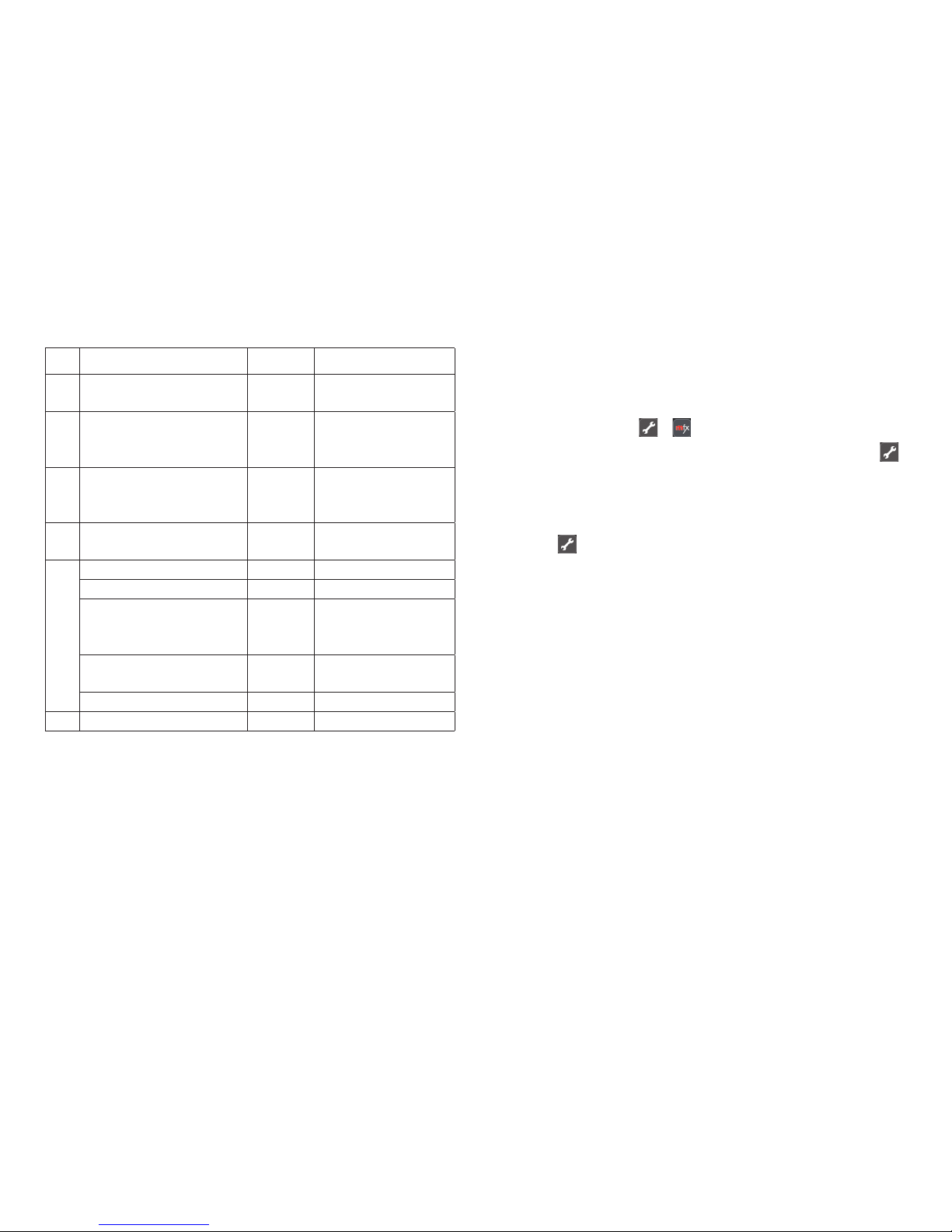
CV Betydelse Värden
8 Dekoder-reset 8 (-) Fabriksinställningar, värden
sparas ej
36 Växellykta
till/från
0-1 (1)
Tillvägagångssättet vid programmering med Central Unit 6021
motsvarar lokprogrammeringen (www.maerklin.de -> Service ->
Technische Informationen).
Page 24
24
DCC
CV Betydelse Värden
1 Adresser, lågvärdiga
Byte
0-255 (1)
7 Tillverkarens versions-
nummer (Mjukvaruversion)
(-) endast läsning
8 Tillverkarens ID
Dekoder reset
(131)
8 (-)
endast läsning,
fabriksinställning,
värden sparas ej
9 Adresser, högvärdiga
Byte
0-7 (0)
29 Konfiguration (192) endast läsning
Bit 0-4 används ej 0
Bit 5: Dekodertyp 0 / 32
Standarddekoder-
eller tillagd tillbehörsdekoder
Bit 6: Adresseringsmetod
0 / 64
Dekoder- eller
utgångsadress
Bit 7: Dekodersort 128 Tillbehörsdekoder
36 Växellykta, från/till 0-1 (1)
Inställning och åtkomst av adresser högre än 255:
T.ex. adress 1044 -> 1044:256= 4,078125. För in detta värde före
kommtecknet (4) i CV 9. Värdet efter kommatecknet (0,078125)
multipliceras med 256, 0,078125x256=20. Det erhållna värdet
måste införas i CV 1.
Körning med mfx
Mfx-inställning kan göras med både MM och DCC.
Drifttyp ställs in med hjälp av dip-switch nr 10.
Mfx-inställningen görs med CS2 60213/60214/60215 i magnetarti-
kelkonfigurationen via >
och med CS3 60216/60226 i magnetartikelkonfigurationen via
>“sökning av mfx-artiklar “.
Information om mfx-inställning med CS2:
Valmöjlighet: “Automatisk tilldelning av magnetartikel“ under
“Setup“> > “spår“.
Om man markerar detta val så genomförs mfx-inställningen på
den första lediga adressen i CS2. Om man inte markerar detta så
genomförs mfx-inställningen på den adress som dekodern redan
är inställd på.
Page 25

25
Hensigtsmæssig anvendelse
• Den digitale indbygningsdekoder er beregnet til indbygning
i Märklin- og Trix C-spor sporskifter med sporskiftestyring
(undtagen Märklin trevejssporskifte).
• Den digitale indbygningsdekoder må ved ekstern strømforsyning kun tilsluttes Märklin hhv. Trix strømforsyninger.
• Må kun anvendes i tørre rum.
Leveringsomfang
1 digital indbygningsdekoder
1 kabel gult, rødt og brunt (C-spor Märklin)
1 kabel blåt, rødt og hvidt (C-spor Trix)
Montagevejledning
Garantibevis
Værktøj, som yderligere kræves til montagen: Pincet og loddeudstyr til en loddetemperatur op til maks. 30W/300˚med tynd
spids, elektronik-loddetin (H 0,5-1 mm), aflodningsbraid eller
aflodningspumpe.
Sikkerhedsbemærkninger
• BEMÆRK! Funktionsbetingede skarpe kanter og spidser.
• Udfør kun kabel- og montagearbejde uden spænding. Hvis
man ikke iagttager dette, kan der forekomme farlige strømme
gennem kroppen, som kan medføre kvæstelser.
• Anvend kun dekoderen med den tilladte spænding (se tekniske data).
I forbindelse med håndtering af loddekolben er der fare for
forbrændinger af huden.
Vigtige bemærkninger
• Bemærk: Undgå ved montagen om muligt at berøre komponenter på den digitale indbygningsdekoders overside, statisk
opladning kan skade funktionen.
• Betjeningsvejledningen er en bestanddel af produktet og skal
derfor gemmes samt gives med, hvis produktet gives videre.
• For reparation bedes du henvende dig til din Märklin
forhandler.
• http://www.maerklin.com/en/imprint.html
Tekniske data
• Belastning laterneudgang ≤ 100 mA
• Belastning sporskifteudgang max. 2 A
• Spænding digitalkredsløb max. 20 V eff.
• Spænding ekstern max. 20 V DC
• Spændingssikring max. 40 V
Funktioner
• Multiprotokoldygtig: fx (MM), mfx* og DCC
• Indstilling af driftsmodus ved hjælp af DIP-kontakt,
se side 38
• Indstillelige adresser med DIP-kontakt:
1-256 fx (MM) (Control Unit 6021 / Central Station 1)
1-320 fx (MM) (Central Station 2/3 / Mobile Station 2)
1-511 (DCC)
• Programmerbare adresser via CV
1-2.044 DCC
• Den sidste adresseindstilling er gyldig, uanset om den er
indstillet via programmering eller DIP-kontakt.
• Ændringer af egenskaberne via CV
• Digitalsignal: Overførsel uafhængig af strømforsyningen
* mfx først fra CS 2 Softwareversion 4.0
Page 26

26
• Strømforsyning via digitalkredsløb
• Alternativ strømforsyning
• Loddepads til tilslutning af sporskiftelaterne
• Sporskiftelaterne kan tændes og slukkes
Indbygning af dekoder
De følgende arbejdsskridt må kun foretages uden elektrisk
spænding.
• Stik det medleverede kabel (vær opmærksom på det rigtige
sporsystem) i det forberedte stik, se side 28/29 (Märklin og
Trix). Følg nu den illustrerede vejledning.
Til ændring af de andre egenskaber i fx (MM) protokollen via
CV programmering eller til DCC CV-programmering følg kapitlet
”CV programmering.”
Bemærk venligst: Foretag altid indstillinger med DIP-kontakten
uden elektrisk spænding. Den digitale indbygningsdekoder
genkender først de gældende indstillinger, når der tændes for
spændingen.
Fra side 39 finder du tabellen til adressering med DIP-kontakten.
Indbygning af den digitale indbygningsdekoder i Märklin stan-
dard-, bue- eller dobbeltkrydssporskifte se side 28.
Alternativ strømforsyning se side 37.
Indbygning af den digitale indbygningsdekoder i Trix standard-,
bue- eller dobbeltkrydssporskifte se side 29.
Alternativ strømforsyning se side 37.
CV programmering
CV programmeringen skal foregå på programmeringssporet.
Til programmeringen anbefaler vi at oprette et fiktivt lokomotiv.
Værdier i parentes er fabriksindstillingerne.
Programmeringen kan valgfrit foretages via fx (MM) eller DCC.
Indstilling af adresse anbefales foretaget via DIP-kontakt til fx
(MM) (se 39 og frem).
fx (MM)
Før programmeringen skal det sporskifte, der skal programmeres, omskiftes fra keyboardet. Derefter skal CV omgående
ændres med Control Unit hhv. Central Stations CV konfiguration.
Derefter skal det nyprogrammerede sporskifte omgående
aktiveres ved hjælp af tastaturet. Først nu er programmeringen
overtaget og i effekt.
CV Betydning Værdier
8 Dekoder-reset 8 (-) Fabriksindstilling, værdi
skrives ikke
36 Sporskiftelaterne
sluk/tænd
0-1 (1)
Fremgangsmåden ved programmering med Central Unit 6021
svarer til lokomotivprogrammeringen (www.maerklin.de ->
Service -> Technische Informationen).
Page 27
27
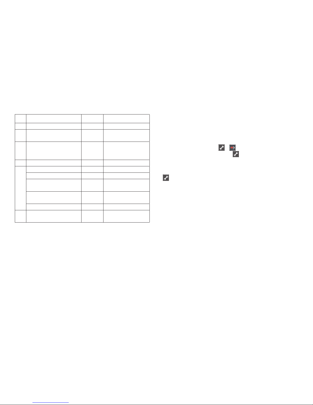
DCC
CV Betydning Værdier
1 Adresse, lavværdi byte 0-255 (1)
7 Producent versionsnum-
mer (softwareversion)
(-) kun læse
8 Producent mærkning ID
dekoder reset
(131)
8 (-)
kun læse,
fabriksindstilling,
værdi skrives ikke
9 Adresse, højværdi byte 0-7 (0)
29 Konfiguration (192) kun læse
Bit 0-4 anvendes ikke 0
Bit 5: dekodertype 0 / 32 basis- el. udvidet
tilbehørsdekoder
Bit 6: adresseringsmetode
0 / 64
dekoder- el. ud-
gangsadresse
Bit 7: dekoderart 128 tilbehørsdekoder
36 Sporskiftelaterne,
sluk/tænd
0-1 (1)
Indstilling og udregning af adresser højere end 255:
F.eks. adresse 1044 -> 1044:256=4,078125 . Værdien foran kommaet (4) skal indgives i CV 9. Værdien efter kommaet (0,078125)
multipliceres med 256, 0,078125x256=20. Den udregnede værdi 20
skal indgives i CV 1.
Drift med mfx
mfx-registreringen kan ske med MM eller DCC.
Den ved hjælp af dip-omskifter indstillede driftsmodus er
afgørende.
mfx-registreringen indledes med CS2 60213/60214/60215 i magne-
tartikelkonfigurationen via > og med CS3 60216/60226 i
magnetartikelkonfigurationen via > „søg mfx-artikel“.
Vigtigt vedrørende mfx-registreringen med CS2:
Valgmulighed „tildel magnetartikel automatisk“ under „Setup“ >
> „Spor“.
Er fluebenet sat ved dette punkt, sker mfx-registreringen på de
første frie adresser i CS2. Er fluebenet ikke sat ved dette punkt,
sker mfx-registreringen på de effektivt ved dekoderen programmerede adresser.
Page 28
28
1 2 3 4 5 6
7
8
9 10
ON
B
B
0
74470 *
* Gehört nicht zum Lieferumfang.
Not included in delivery scope.
Ne fait pas partie de la fourniture.
Maakt geen deel uit van het
leveringspakket.
No está incluido en el conjunto
de piezas suministradas.
Non incl. nella fornitura.
Ingår inte i leveransen.
Medleveres ikke.
Märklin C-Gleis / Märklin C Track / Voie C Märklin / Märklin C-rail /
Vía C de Märklin / Binario Märklin C / Märklin C-skenor / Märklin C-spor
Page 29
29
1 2 3
4 5 6
7
8
9 10
ON
Trix C-Gleis / Trix C Track / Voie C Trix /
Trix C-rail / Vía C de Trix / Binario Trix C /
Trix C-skenor / Trix C-spor
74470 *
* Gehört nicht zum Lieferumfang.
Not included in delivery scope.
Ne fait pas partie de la fourniture.
Maakt geen deel uit van het
leveringspakket.
No está incluido en el conjunto
de piezas suministradas.
Non incl. nella fornitura.
Ingår inte i leveransen.
Medleveres ikke.
Page 30
30
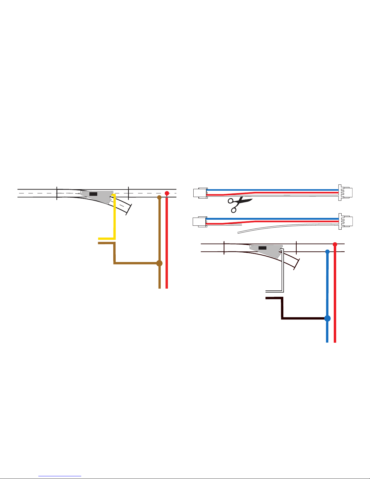
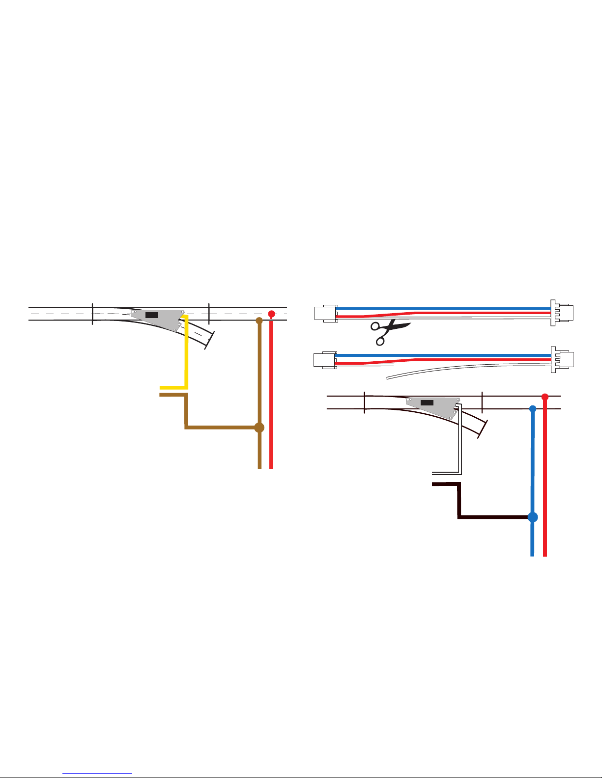
Alternative Stromversorgung Märklin:
Verbinden Sie das gelbe Kabel mit einer externen Stromquelle.
Den anderen freien Pol der externen Stromversorgung verbinden
Sie mit dem braunen Kabel des Digital-Stromkreises.
Das gelbe Kabel des Einbau-Digital-Decoders darf nicht zusätzlich mit dem Digital-Stromkreis verbunden werden.
DC
max. 20V
Digital
.........
.
O
N
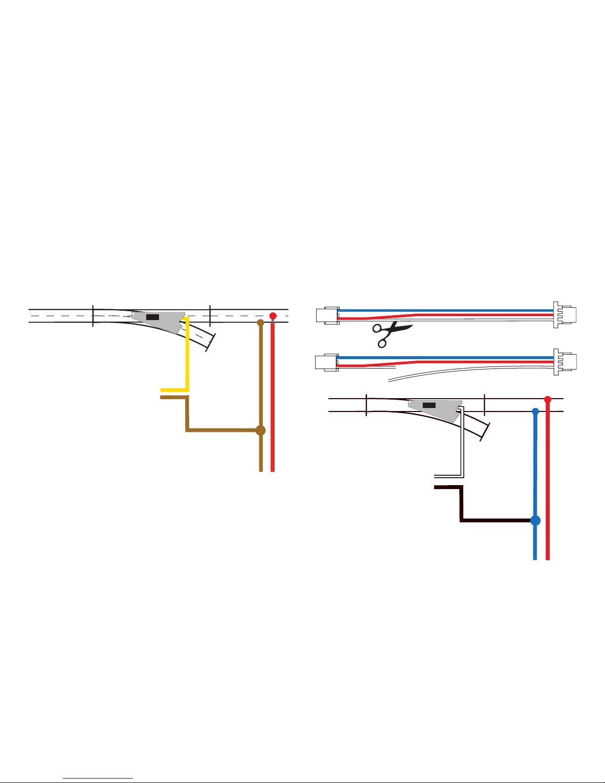
Alternative Stromversorgung Trix:
Durchtrennen Sie das weiße Kabel und verbinden Sie es mit
einer externen Stromquelle. Den anderen freien Pol der externen
Stromversorgung verbinden Sie mit dem Massekabel (braun/
blau) des Digital-Stromkreises.
Das weiße Kabel des Einbau-Digital-Decoders darf nicht mit
dem Digital-Stromkreis verbunden werden.
DC
max. 20V
Digital
.........
.
O
N
DC
Page 31
31
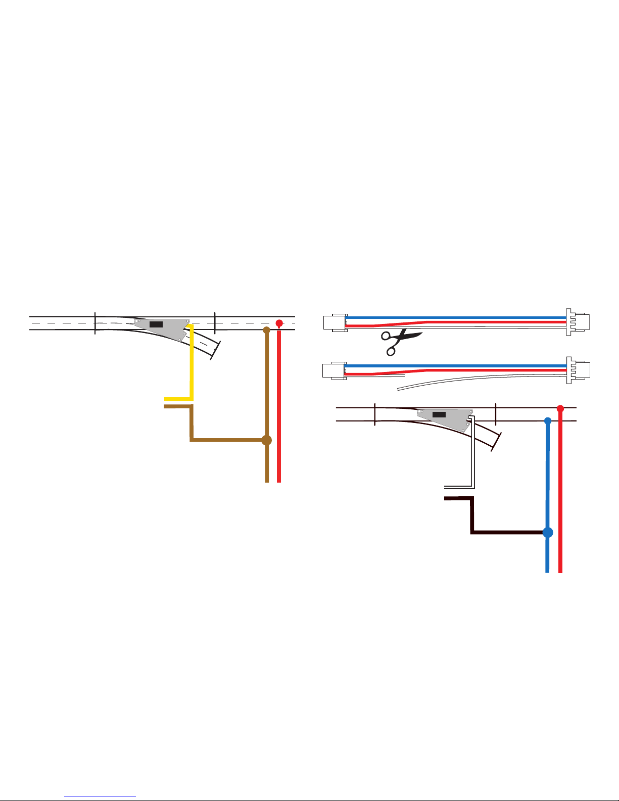
Alternative Power Supply for Märklin:
Connect the yellow wire to an external power source. The
other available terminal on the external power supply can be
connected to the brown wire for the digital power circuit.
The yellow wire from the digital installation decoder may not
be connected with the digital power circuit.
DC
max. 20V
Digital
.........
.
O
N
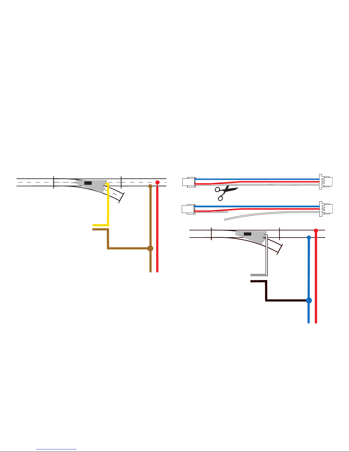
Alternative Power Supply for Trix:
Cut the white wire as shown and connect it to an external power
source. The other available terminal on the external power
supply can be connected to the ground wire (brown/blue) for the
digital power circuit.
The white wire from the digital installation decoder may not be
connected with the digital power circuit.
DC
max. 20V
Digital
.........
.
O
N
DC
Page 32
32
Alimentation en courant alternative Märklin :
Reliez le câble jaune à une source d’alimentation extérieure. Reliez le second pôle libre de l’alimentation en courant extérieure
avec le câble marron du circuit électrique numérique.
Le câble jaune du décodeur numérique ne doit en aucun cas
être raccordé au circuit électrique numérique.
DC
max. 20V
Digital
.........
.
O
N
Alimentation en courant alternative Trix :
Sectionnez le câble blanc et reliez-le à une source
d’alimentation en courant extérieure. Reliez le second pôle libre
de l’alimentation en courant extérieure avec le câble de masse
(marron/bleu) du circuit électrique numérique.
Le câble blanc du décodeur numérique ne doit en aucun cas
être raccordé au circuit électrique numérique.
DC
max. 20V
Digital
.........
.
O
N
DC
Page 33
33
Alternatieve stroomvoorziening Märklin:
Verbind de gele draad met een externe stroombron. De andere
vrije aansluiting van de externe stroombron moet worden verbonden met de bruine draad van de digitale stroomkring.
De gele draad van de inbouw-digitaaldecoder mag niet met de
digitale stroomkring verbonden worden.
DC
max. 20V
Digital
.........
.
O
N
Alternatieve stroomvoorziening Trix:
Knip de witte draad door en verbind deze draad met een externe
stroombron. De andere vrije aansluiting van de externe stroombron moet worden verbonden met de massadraad (bruine/blauwe) draad van de digitale stroomkring.
De witte draad van de inbouw-digitaaldecoder mag niet met de
digitale stroomkring verbonden worden.
DC
max. 20V
Digital
.........
.
O
N
DC
Page 34
34
Alimentazione di corrente alternativa Märklin:
Vogliate collegare il cavetto giallo con una sorgente di corrente
esterna. L’altro polo libero dell’alimentazione di corrente esterna
collegatelo con il cavetto marrone del circuito di corrente
Digital.
Il cavetto giallo del Decoder Digital installabile non deve venire
collegato con il circuito di corrente Digital.
DC
max. 20V
Digital
.........
.
O
N
Alimentazione di corrente alternativa Trix:
Vogliate sezionare il cavetto bianco e collegatelo con una sorgente di corrente esterna. L’altro polo libero dell’alimentazione di
corrente esterna collegatelo con il cavetto di massa (marrone/
blu) del circuito di corrente Digital.
Il cavetto bianco del Decoder Digital installabile non deve
venire collegato con il circuito di corrente Digital.
DC
max. 20V
Digital
.........
.
O
N
DC
Page 35
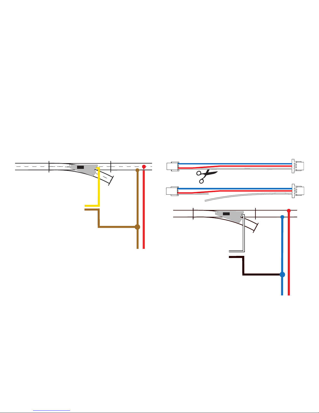
35
Alimentación eléctrica de Märklin:
Conecte el cable amarillo a una fuente de corriente externa.
Conecte el otro polo libre de la alimentación eléctrica externa al
cable marrón del circuito digital.
El cable amarillo del decoder digital integrable no debe conectarse con el circuito digital.
DC
max. 20V
Digital
.........
.
O
N
Alimentación eléctrica alternativa Trix:
Seccione el cable blanco y conéctelo a una fuente de corriente
externa. Conecte el otro polo libre de la fuente de alimentación
externa al cable de masa (marrón/azul) de circuito digital.
El cable blanco del decoder digital integrable no debe conectarse al circuito digital.
DC
max. 20V
Digital
.........
.
O
N
DC
Page 36
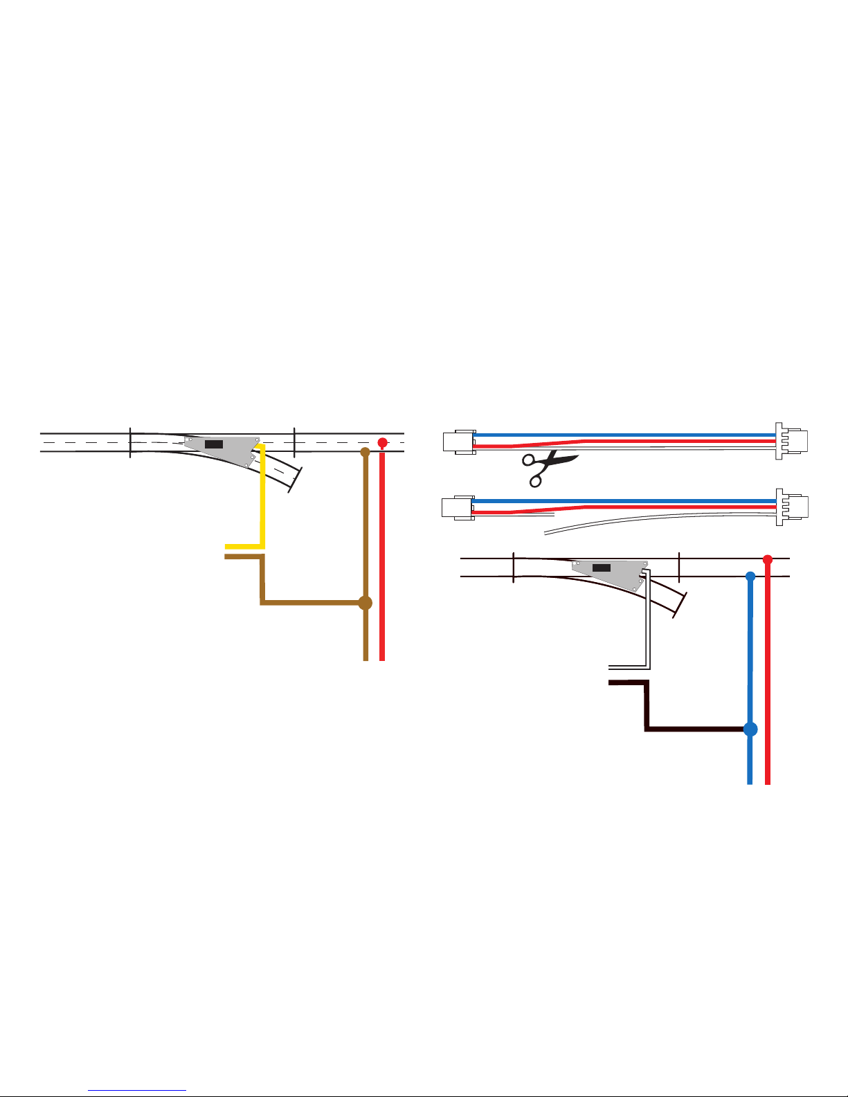
36
Alternativ strömförsörjning Märklin:
Den gula kabeln skall anslutas till en extern strömkälla. Den
andra polen på den externa strömkällan ansluts till den digitala
strömkretsens bruna kabel.
Inbyggnadsdekoderns gula kabel får absolut INTE komma i
kontakt med den digitala strömkretsen.
DC
max. 20V
Digital
.........
.
O
N
Alternativ strömförsörjning Trix:
Separera den vita kabeln och koppla den till en extern strömkälla. Den andra polen på den externa strömkällan ansluts till den
digitala strömkretsens jordkabel (brun/blå).
Den vita kabeln får absolut INTE komma i kontakt med den
digitala strömkretsen.
DC
max. 20V
Digital
.........
.
O
N
DC
Page 37
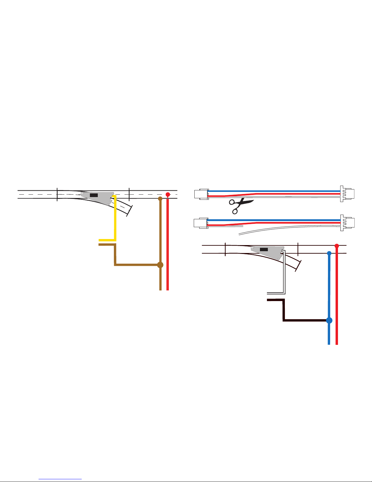
37
Alternativ strømforsyning Märklin:
Forbind det gule kabel med en ekstern strømkilde. Den eksterne
strømforsynings anden fri pol forbindes med det digitale strømkredsløbs brune kabel.
Den digitale indbygningsdekoders gule kabel må ikke forbindes
med det digitale strømkredsløb.
DC
max. 20V
Digital
.........
.
O
N
Alternativ strømforsyning Trix:
Klip det hvide kabel over og forbind det med en ekstern strømkilde. Den eksterne strømforsynings anden fri pol forbindes med
det digitale strømkredsløbs jordkabel (brun/blå).
Den digitale indbygningsdekoders hvide kabel må ikke forbindes med det digitale strømkredsløb.
DC
max. 20V
Digital
.........
.
O
N
DC
Page 38
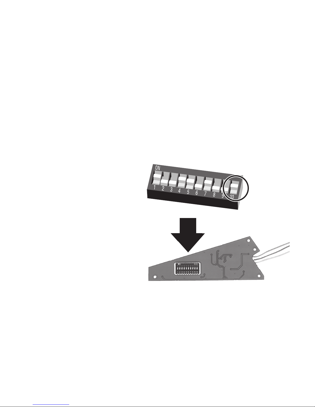
38
on = DCC
off = fx (MM)
Betriebsart und Adressen einstellen
Pos 10: on = DCC, off = fx (MM)
Setting the mode of operation and addresses
Pos 10: on = DCC, off = fx (MM)
Définir le mode d’exploitation et les adresses
Pos 10: on = DCC, off = fx (MM)
Bedrijfsmodus en adres instellen
Pos 10: on = DCC, off = fx (MM)
Configuración de modo de funcionamiento y
direcciones
Pos 10: on = DCC, off = fx (MM)
Impostate tipo di funzionamento e indirizzi
Pos 10: on = DCC, off = fx (MM)
Ställ in driftstyp och adress
Pos 10: on = DCC, off = fx (MM)
Indstil driftsart og adresser
Pos 10: on = DCC, off = fx (MM)
Page 39
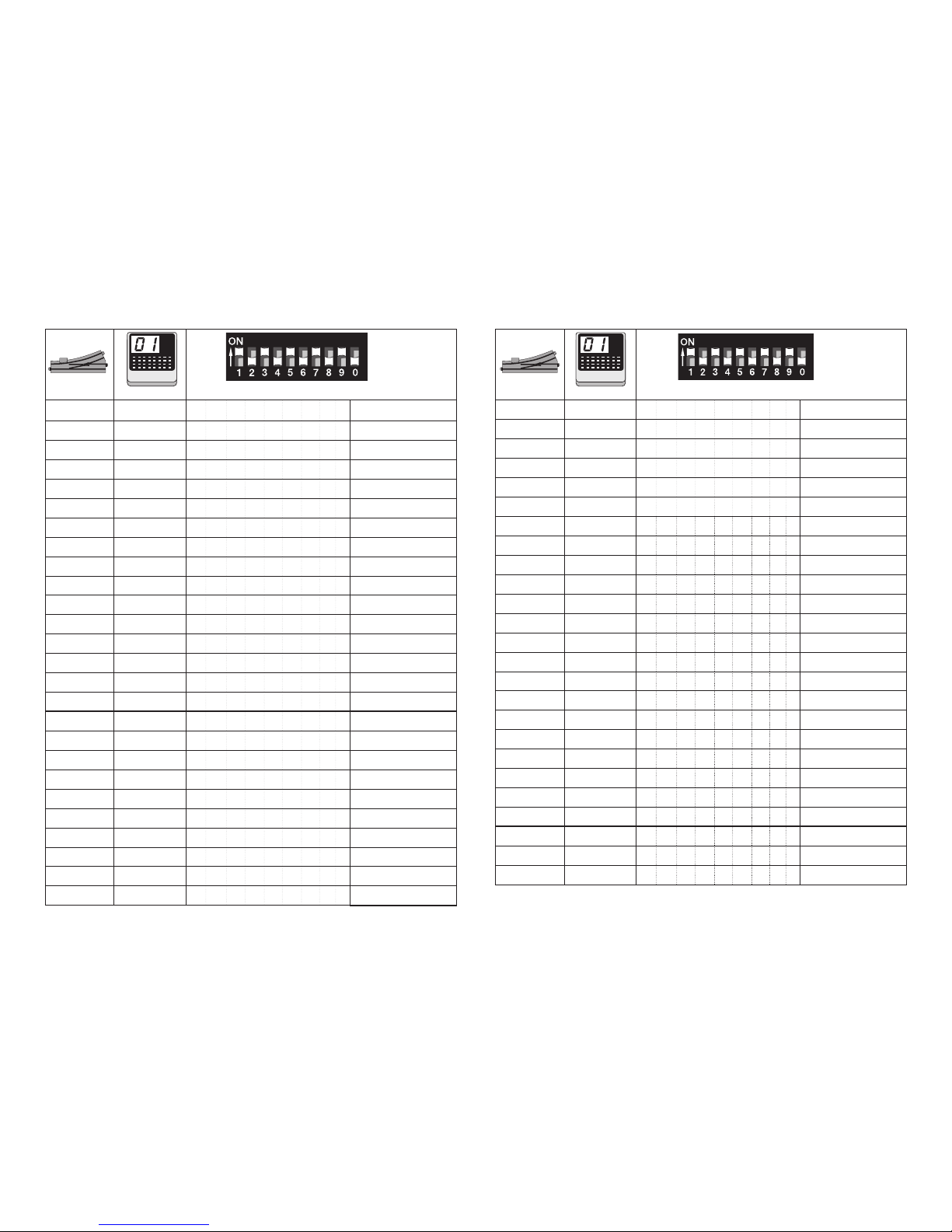
39
10 ( 0/1 )
27 2 11 1 2 4 5 fx (MM)/DCC
28 2 12 3 4 5 fx (MM)/DCC
29 2 13 1 3 4 5 fx (MM)/DCC
30 2 14 2 3 4 5 fx (MM)/DCC
31 2 15 1 2 3 4 5 fx (MM)/DCC
32 2 16 6 fx (MM)/DCC
33 3 1 1 6 fx (MM)/DCC
34 3 2 2 6 fx (MM)/DCC
35 3 3 1 2 6 fx (MM)/DCC
36 3 4 3 6 fx (MM)/DCC
37 3 5 1 3 6 fx (MM)/DCC
38 3 6 2 3 6 fx (MM)/DCC
39 3 7 1 2 3 6 fx (MM)/DCC
40 3 8 4 6 fx (MM)/DCC
41 3 9 1 4 6 fx (MM)/DCC
42 3 10 2 4 6 fx (MM)/DCC
43 3 11 1 2 4 6 fx (MM)/DCC
44 3 12 3 4 6 fx (MM)/DCC
45 3 13 1 3 4 6 fx (MM)/DCC
46 3 14 2 3 4 6 fx (MM)/DCC
47 3 15 1 2 3 4 6 fx (MM)/DCC
48 3 16 5 6 fx (MM)/DCC
49 4 1 1 5 6 fx (MM)/DCC
50 4 2 2 5 6 fx (MM)/DCC
51 4 3 1 2 5 6 fx (MM)/DCC
10 ( 0/1 )
1 1 1 1 fx (MM)/DCC
2 1 2 2 fx (MM)/DCC
3 1 3 1 2 fx (MM)/DCC
4 1 4 3 fx (MM)/DCC
5 1 5 1 3 fx (MM)/DCC
6 1 6 2 3 fx (MM)/DCC
7 1 7 1 2 3 fx (MM)/DCC
8 1 8 4 fx (MM)/DCC
9 1 9 1 4 fx (MM)/DCC
10 1 10 2 4 fx (MM)/DCC
11 1 11 1 2 4 fx (MM)/DCC
12 1 12 3 4 fx (MM)/DCC
13 1 13 1 3 4 fx (MM)/DCC
14 1 14 2 3 4 fx (MM)/DCC
15 1 15 1 2 3 4 fx (MM)/DCC
16 1 16 5 fx (MM)/DCC
17 2 1 1 5 fx (MM)/DCC
18 2 2 2 5 fx (MM)/DCC
19 2 3 1 2 5 fx (MM)/DCC
20 2 4 3 5 fx (MM)/DCC
21 2 5 1 3 5 fx (MM)/DCC
22 2 6 2 3 5 fx (MM)/DCC
23 2 7 1 2 3 5 fx (MM)/DCC
24 2 8 4 5 fx (MM)/DCC
25 2 9 1 4 5 fx (MM)/DCC
26 2 10 2 4 5 fx (MM)/DCC
keyboard
keyboard
Page 40
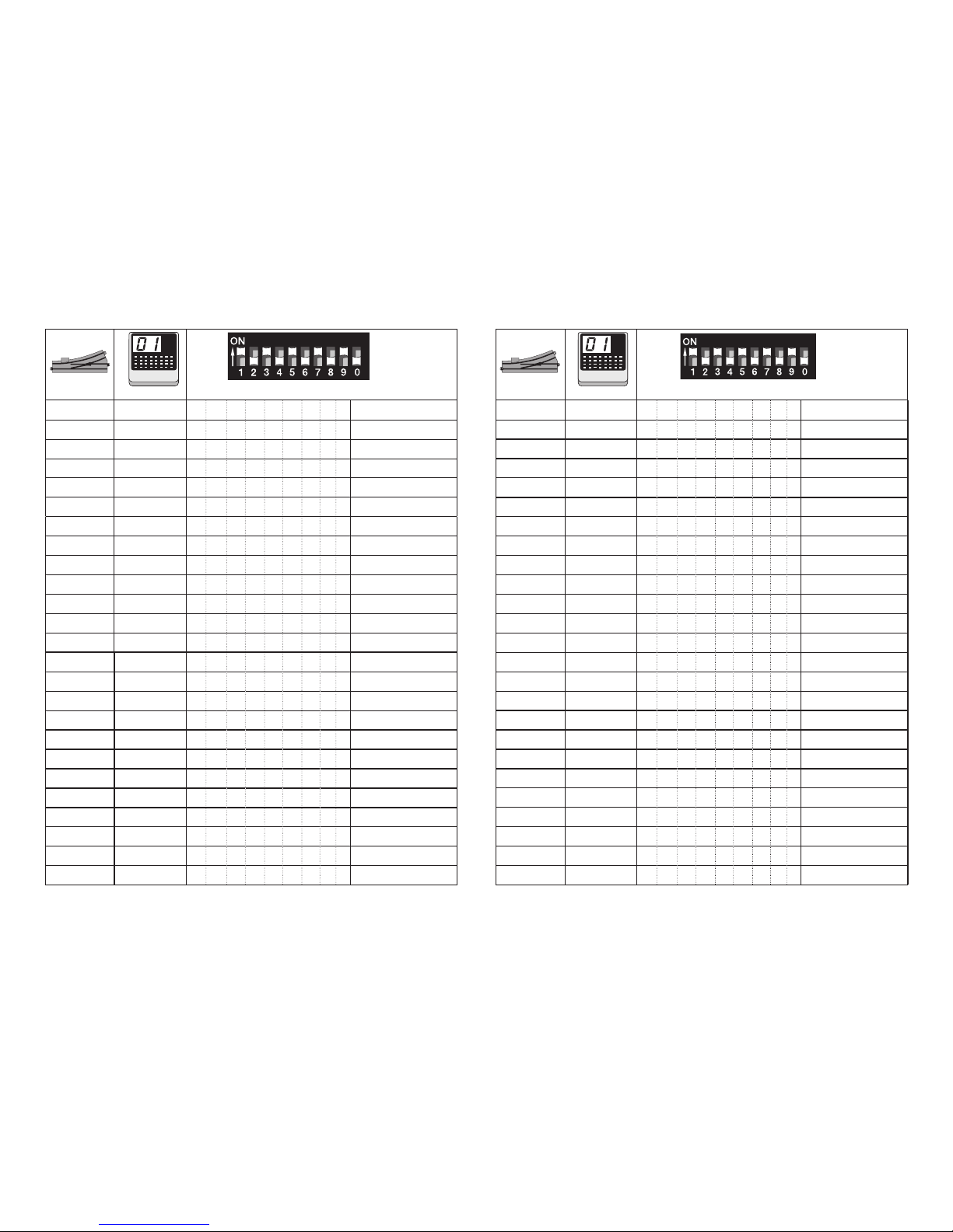
40
10 ( 0/1 )
52 4 4 3 5 6 fx (MM)/DCC
53 4 5 1 3 5 6 fx (MM)/DCC
54 4 6 2 3 5 6 fx (MM)/DCC
55 4 7 1 2 3 5 6 fx (MM)/DCC
56 4 8 4 5 6 fx (MM)/DCC
57 4 9 1 4 5 6 fx (MM)/DCC
58 4 10 2 4 5 6 fx (MM)/DCC
59 4 11 1 2 4 5 6 fx (MM)/DCC
60 4 12 3 4 5 6 fx (MM)/DCC
61 4 13 1 3 4 5 6 fx (MM)/DCC
62 4 14 2 3 4 5 6 fx (MM)/DCC
63 4 15 1 2 3 4 5 6 fx (MM)/DCC
64 4 16 7 fx (MM)/DCC
65 5 1 1 7 fx (MM)/DCC
66 5 2 2 7 fx (MM)/DCC
67 5 3 1 2 7 fx (MM)/DCC
68 5 4 3 7 fx (MM)/DCC
69 5 5 1 3 7 fx (MM)/DCC
70 5 6 2 3 7 fx (MM)/DCC
71 5 7 1 2 3 7 fx (MM)/DCC
72 5 8 4 7 fx (MM)/DCC
73 5 9 1 4 7 fx (MM)/DCC
74 5 10 2 4 7 fx (MM)/DCC
75 5 11 1 2 4 7 fx (MM)/DCC
76 5 12 3 4 7 fx (MM)/DCC
10 ( 0/1 )
77 5 13 1 3 4 7 fx (MM)/DCC
78 5 14 2 3 4 7 fx (MM)/DCC
79 5 15 1 2 3 4 7 fx (MM)/DCC
80 5 16 5 7 fx (MM)/DCC
81 6 1 1 5 7 fx (MM)/DCC
82 6 2 2 5 7 fx (MM)/DCC
83 6 3 1 2 5 7 fx (MM)/DCC
84 6 4 3 5 7 fx (MM)/DCC
85 6 5 1 3 5 7 fx (MM)/DCC
86 6 6 2 3 5 7 fx (MM)/DCC
87 6 7 1 2 3 5 7 fx (MM)/DCC
88 6 8 4 5 7 fx (MM)/DCC
89 6 9 1 4 5 7 fx (MM)/DCC
90 6 10 2 4 5 7 fx (MM)/DCC
91 6 11 1 2 4 5 7 fx (MM)/DCC
92 6 12 3 4 5 7 fx (MM)/DCC
93 6 13 1 3 4 5 7 fx (MM)/DCC
94 6 14 2 3 4 5 7 fx (MM)/DCC
95 6 15 1 2 3 4 5 7 fx (MM)/DCC
96 6 16 6 7 fx (MM)/DCC
97 7 1 1 6 7 fx (MM)/DCC
98 7 2 2 6 7 fx (MM)/DCC
99 7 3 1 2 6 7 fx (MM)/DCC
100 7 4 3 6 7 fx (MM)/DCC
101 7 5 1 3 6 7 fx (MM)/DCC
keyboard
keyboard
Page 41
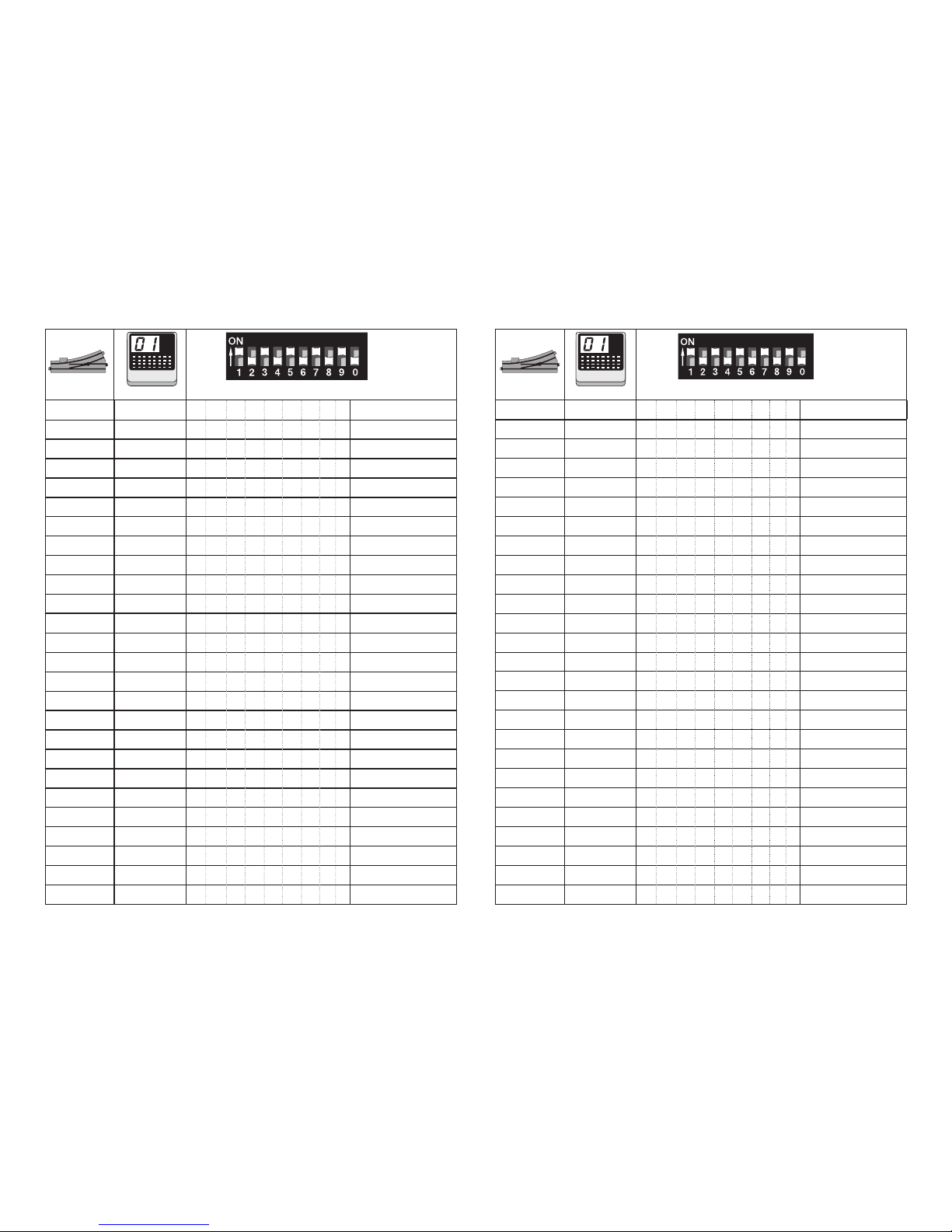
41
10 ( 0/1 )
102 7 6 2 3 6 7 fx (MM)/DCC
103 7 7 1 2 3 6 7 fx (MM)/DCC
104 7 8 4 6 7 fx (MM)/DCC
105 7 9 1 4 6 7 fx (MM)/DCC
106 7 10 2 4 6 7 fx (MM)/DCC
107 7 11 1 2 4 6 7 fx (MM)/DCC
108 7 12 3 4 6 7 fx (MM)/DCC
109 7 13 1 3 4 6 7 fx (MM)/DCC
110 7 14 2 3 4 6 7 fx (MM)/DCC
111 7 15 1 2 3 4 6 7 fx (MM)/DCC
112 7 16 5 6 7 fx (MM)/DCC
113 8 1 1 5 6 7 fx (MM)/DCC
114 8 2 2 5 6 7 fx (MM)/DCC
115 8 3 1 2 5 6 7 fx (MM)/DCC
116 8 4 3 5 6 7 fx (MM)/DCC
117 8 5 1 3 5 6 7 fx (MM)/DCC
118 8 6 2 3 5 6 7 fx (MM)/DCC
119 8 7 1 2 3 5 6 7 fx (MM)/DCC
120 8 8 4 5 6 7 fx (MM)/DCC
121 8 9 1 4 5 6 7 fx (MM)/DCC
122 8 10 2 4 5 6 7 fx (MM)/DCC
123 8 11 1 2 4 5 6 7 fx (MM)/DCC
124 8 12 3 4 5 6 7 fx (MM)/DCC
125 8 13 1 3 4 5 6 7 fx (MM)/DCC
126 8 14 2 3 4 5 6 7 fx (MM)/DCC
127 8 15 1 2 3 4 5 6 7 fx (MM)/DCC
10 ( 0/1 )
128 8 16 8 fx (MM)/DCC
129 9 1 1 8 fx (MM)/DCC
130 9 2 2 8 fx (MM)/DCC
131 9 3 1 2 8 fx (MM)/DCC
132 9 4 3 8 fx (MM)/DCC
133 9 5 1 3 8 fx (MM)/DCC
134 9 6 2 3 8 fx (MM)/DCC
135 9 7 1 2 3 8 fx (MM)/DCC
136 9 8 4 8 fx (MM)/DCC
137 9 9 1 4 8 fx (MM)/DCC
138 9 10 2 4 8 fx (MM)/DCC
139 9 11 1 2 4 8 fx (MM)/DCC
140 9 12 3 4 8 fx (MM)/DCC
141 9 13 1 3 4 8 fx (MM)/DCC
142 9 14 2 3 4 8 fx (MM)/DCC
143 9 15 1 2 3 4 8 fx (MM)/DCC
144 9 16 5 8 fx (MM)/DCC
145 10 1 1 5 8 fx (MM)/DCC
146 10 2 2 5 8 fx (MM)/DCC
147 10 3 1 2 5 8 fx (MM)/DCC
148 10 4 3 5 8 fx (MM)/DCC
149 10 5 1 3 5 8 fx (MM)/DCC
150 10 6 2 3 5 8 fx (MM)/DCC
151 10 7 1 2 3 5 8 fx (MM)/DCC
152 10 8 4 5 8 fx (MM)/DCC
153 10 9 1 4 5 8 fx (MM)/DCC
keyboard
keyboard
Page 42
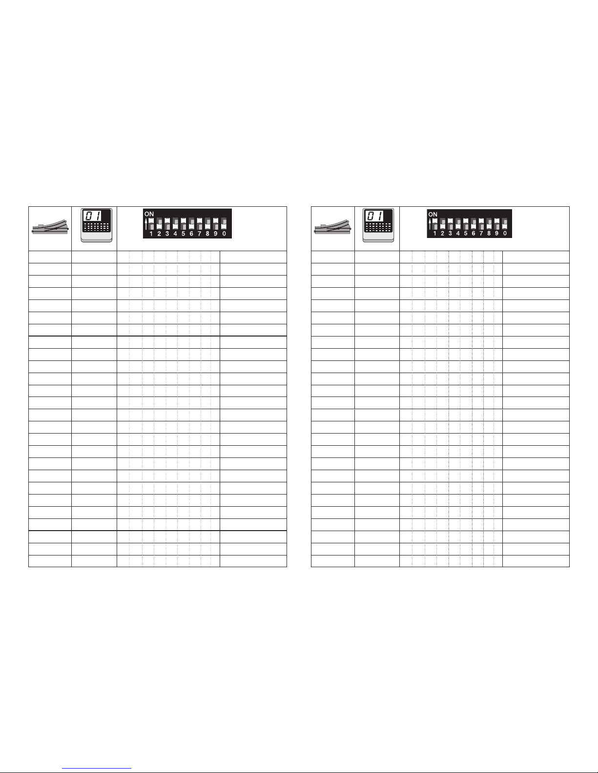
42
10 ( 0/1 )
154 10 10 2 4 5 8 fx (MM)/DCC
155 10 11 1 2 4 5 8 fx (MM)/DCC
156 10 12 3 4 5 8 fx (MM)/DCC
157 10 13 1 3 4 5 8 fx (MM)/DCC
158 10 14 2 3 4 5 8 fx (MM)/DCC
159 10 15 1 2 3 4 5 8 fx (MM)/DCC
160 10 16 6 8 fx (MM)/DCC
161 11 1 1 6 8 fx (MM)/DCC
162 11 2 2 6 8 fx (MM)/DCC
163 11 3 1 2 6 8 fx (MM)/DCC
164 11 4 3 6 8 fx (MM)/DCC
165 11 5 1 3 6 8 fx (MM)/DCC
166 11 6 2 3 6 8 fx (MM)/DCC
167 11 7 1 2 3 6 8 fx (MM)/DCC
168 11 8 4 6 8 fx (MM)/DCC
169 11 9 1 4 6 8 fx (MM)/DCC
170 11 10 2 4 6 8 fx (MM)/DCC
171 11 11 1 2 4 6 8 fx (MM)/DCC
172 11 12 3 4 6 8 fx (MM)/DCC
173 11 13 1 3 4 6 8 fx (MM)/DCC
174 11 14 2 3 4 6 8 fx (MM)/DCC
175 11 15 1 2 3 4 6 8 fx (MM)/DCC
176 11 16 5 6 8 fx (MM)/DCC
177 12 1 1 5 6 8 fx (MM)/DCC
178 12 2 2 5 6 8 fx (MM)/DCC
179 12 3 1 2 5 6 8 fx (MM)/DCC
10 ( 0/1 )
180 12 4 3 5 6 8 fx (MM)/DCC
181 12 5 1 3 5 6 8 fx (MM)/DCC
182 12 6 2 3 5 6 8 fx (MM)/DCC
183 12 7 1 2 3 5 6 8 fx (MM)/DCC
184 12 8 4 5 6 8 fx (MM)/DCC
185 12 9 1 4 5 6 8 fx (MM)/DCC
186 12 10 2 4 5 6 8 fx (MM)/DCC
187 12 11 1 2 4 5 6 8 fx (MM)/DCC
188 12 12 3 4 5 6 8 fx (MM)/DCC
189 12 13 1 3 4 5 6 8 fx (MM)/DCC
190 12 14 2 3 4 5 6 8 fx (MM)/DCC
191 12 15 1 2 3 4 5 6 8 fx (MM)/DCC
192 12 16 7 8 fx (MM)/DCC
193 13 1 1 7 8 fx (MM)/DCC
194 13 2 2 7 8 fx (MM)/DCC
195 13 3 1 2 7 8 fx (MM)/DCC
196 13 4 3 7 8 fx (MM)/DCC
197 13 5 1 3 7 8 fx (MM)/DCC
198 13 6 2 3 7 8 fx (MM)/DCC
199 13 7 1 2 3 7 8 fx (MM)/DCC
200 13 8 4 7 8 fx (MM)/DCC
201 13 9 1 4 7 8 fx (MM)/DCC
202 13 10 2 4 7 8 fx (MM)/DCC
203 13 11 1 2 4 7 8 fx (MM)/DCC
204 13 12 3 4 7 8 fx (MM)/DCC
205 13 13 1 3 4 7 8 fx (MM)/DCC
keyboard
keyboard
Page 43
43
10 ( 0/1 )
206 13 14 2 3 4 7 8 fx (MM)/DCC
207 13 15 1 2 3 4 7 8 fx (MM)/DCC
208 13 16 5 7 8 fx (MM)/DCC
209 14 1 1 5 7 8 fx (MM)/DCC
210 14 2 2 5 7 8 fx (MM)/DCC
211 14 3 1 2 5 7 8 fx (MM)/DCC
212 14 4 3 5 7 8 fx (MM)/DCC
213 14 5 1 3 5 7 8 fx (MM)/DCC
214 14 6 2 3 5 7 8 fx (MM)/DCC
215 14 7 1 2 3 5 7 8 fx (MM)/DCC
216 14 8 4 5 7 8 fx (MM)/DCC
217 14 9 1 4 5 7 8 fx (MM)/DCC
218 14 10 2 4 5 7 8 fx (MM)/DCC
219 14 11 1 2 4 5 7 8 fx (MM)/DCC
220 14 12 3 4 5 7 8 fx (MM)/DCC
221 14 13 1 3 4 5 7 8 fx (MM)/DCC
222 14 14 2 3 4 5 7 8 fx (MM)/DCC
223 14 15 1 2 3 4 5 7 8 fx (MM)/DCC
224 14 16 6 7 8 fx (MM)/DCC
225 15 1 1 6 7 8 fx (MM)/DCC
226 15 2 2 6 7 8 fx (MM)/DCC
227 15 3 1 2 6 7 8 fx (MM)/DCC
228 15 4 3 6 7 8 fx (MM)/DCC
229 15 5 1 3 6 7 8 fx (MM)/DCC
230 15 6 2 3 6 7 8 fx (MM)/DCC
231 15 7 1 2 3 6 7 8 fx (MM)/DCC
10 ( 0/1 )
232 15 8 4 6 7 8 fx (MM)/DCC
233 15 9 1 4 6 7 8 fx (MM)/DCC
234 15 10 2 4 6 7 8 fx (MM)/DCC
235 15 11 1 2 4 6 7 8 fx (MM)/DCC
236 15 12 3 4 6 7 8 fx (MM)/DCC
237 15 13 1 3 4 6 7 8 fx (MM)/DCC
238 15 14 2 3 4 6 7 8 fx (MM)/DCC
239 15 15 1 2 3 4 6 7 8 fx (MM)/DCC
240 15 16 5 6 7 8 fx (MM)/DCC
241 16 1 1 5 6 7 8 fx (MM)/DCC
242 16 2 2 5 6 7 8 fx (MM)/DCC
243 16 3 1 2 5 6 7 8 fx (MM)/DCC
244 16 4 3 5 6 7 8 fx (MM)/DCC
245 16 5 1 3 5 6 7 8 fx (MM)/DCC
246 16 6 2 3 5 6 7 8 fx (MM)/DCC
247 16 7 1 2 3 5 6 7 8 fx (MM)/DCC
248 16 8 4 5 6 7 8 fx (MM)/DCC
249 16 9 1 4 5 6 7 8 fx (MM)/DCC
250 16 10 2 4 5 6 7 8 fx (MM)/DCC
251 16 11 1 2 4 5 6 7 8 fx (MM)/DCC
252 16 12 3 4 5 6 7 8 fx (MM)/DCC
253 16 13 1 3 4 5 6 7 8 fx (MM)/DCC
254 16 14 2 3 4 5 6 7 8 fx (MM)/DCC
255 16 15 1 2 3 4 5 6 7 8 fx (MM)/DCC
256 16 16 9 fx (MM)/DCC
257 17 1 1 9 fx (MM)/DCC
keyboard
keyboard
Page 44
44
10 ( 0/1 )
258 17 2 2 9 fx (MM)/DCC
259 17 3 1 2 9 fx (MM)/DCC
260 17 4 3 9 fx (MM)/DCC
261 17 5 1 3 9 fx (MM)/DCC
262 17 6 2 3 9 fx (MM)/DCC
263 17 7 1 2 3 9 fx (MM)/DCC
264 17 8 4 9 fx (MM)/DCC
265 17 9 1 4 9 fx (MM)/DCC
266 17 10 2 4 9 fx (MM)/DCC
267 17 11 1 2 4 9 fx (MM)/DCC
268 17 12 3 4 9 fx (MM)/DCC
269 17 13 1 3 4 9 fx (MM)/DCC
270 17 14 2 3 4 9 fx (MM)/DCC
271 17 15 1 2 3 4 9 fx (MM)/DCC
272 17 16 5 9 fx (MM)/DCC
273 18 1 1 5 9 fx (MM)/DCC
274 18 2 2 5 9 fx (MM)/DCC
275 18 3 1 2 5 9 fx (MM)/DCC
276 18 4 3 5 9 fx (MM)/DCC
277 18 5 1 3 5 9 fx (MM)/DCC
278 18 6 2 3 5 9 fx (MM)/DCC
279 18 7 1 2 3 5 9 fx (MM)/DCC
280 18 8 4 5 9 fx (MM)/DCC
281 18 9 1 4 5 9 fx (MM)/DCC
282 18 10 2 4 5 9 fx (MM)/DCC
283 18 11 1 2 4 5 9 fx (MM)/DCC
10 ( 0/1 )
284 18 12 3 4 5 9 fx (MM)/DCC
285 18 13 1 3 4 5 9 fx (MM)/DCC
286 18 14 2 3 4 5 9 fx (MM)/DCC
287 18 15 1 2 3 4 5 9 fx (MM)/DCC
288 18 16 6 9 fx (MM)/DCC
289 19 1 1 6 9 fx (MM)/DCC
290 19 2 2 6 9 fx (MM)/DCC
291 19 3 1 2 6 9 fx (MM)/DCC
292 19 4 3 6 9 fx (MM)/DCC
293 19 5 1 3 6 9 fx (MM)/DCC
294 19 6 2 3 6 9 fx (MM)/DCC
295 19 7 1 2 3 6 9 fx (MM)/DCC
296 19 8 4 6 9 fx (MM)/DCC
297 19 9 1 4 6 9 fx (MM)/DCC
298 19 10 2 4 6 9 fx (MM)/DCC
299 19 11 1 2 4 6 9 fx (MM)/DCC
300 19 12 3 4 6 9 fx (MM)/DCC
301 19 13 1 3 4 6 9 fx (MM)/DCC
302 19 14 2 3 4 6 9 fx (MM)/DCC
303 19 15 1 2 3 4 6 9 fx (MM)/DCC
304 19 16 5 6 9 fx (MM)/DCC
305 20 1 1 5 6 9 fx (MM)/DCC
306 20 2 2 5 6 9 fx (MM)/DCC
307 20 3 1 2 5 6 9 fx (MM)/DCC
308 20 4 3 5 6 9 fx (MM)/DCC
309 20 5 1 3 5 6 9 fx (MM)/DCC
keyboard
keyboard
Page 45
45
10 ( 0/1 )
310 20 6 2 3 5 6 9 fx (MM)/DCC
311 20 7 1 2 3 5 6 9 fx (MM)/DCC
312 20 8 4 5 6 9 fx (MM)/DCC
313 20 9 1 4 5 6 9 fx (MM)/DCC
314 20 10 2 4 5 6 9 fx (MM)/DCC
315 20 11 1 2 4 5 6 9 fx (MM)/DCC
316 20 12 3 4 5 6 9 fx (MM)/DCC
317 20 13 1 3 4 5 6 9 fx (MM)/DCC
318 20 14 2 3 4 5 6 9 fx (MM)/DCC
319 20 15 1 2 3 4 5 6 9 fx (MM)/DCC
320 20 16 7 9 fx (MM)/DCC
321 21 1 1 7 9 - - - / DCC
322 21 2 2 7 9 - - - / DCC
323 21 3 1 2 7 9 - - - / DCC
324 21 4 3 7 9 - - - / DCC
325 21 5 1 3 7 9 - - - / DCC
326 21 6 2 3 7 9 - - - / DCC
327 21 7 1 2 3 7 9 - - - / DCC
328 21 8 4 7 9 - - - / DCC
329 21 9 1 4 7 9 - - - / DCC
330 21 10 2 4 7 9 - - - / DCC
331 21 11 1 2 4 7 9 - - - / DCC
332 21 12 3 4 7 9 - - - / DCC
333 21 13 1 3 4 7 9 - - - / DCC
334 21 14 2 3 4 7 9 - - - / DCC
335 21 15 1 2 3 4 7 9 - - - / DCC
10 ( 0/1 )
336 21 16 5 7 9 - - - / DCC
337 22 1 1 5 7 9 - - - / DCC
338 22 2 2 5 7 9 - - - / DCC
339 22 3 1 2 5 7 9 - - - / DCC
340 22 4 3 5 7 9 - - - / DCC
341 22 5 1 3 5 7 9 - - - / DCC
342 22 6 2 3 5 7 9 - - - / DCC
343 22 7 1 2 3 5 7 9 - - - / DCC
344 22 8 4 5 7 9 - - - / DCC
345 22 9 1 4 5 7 9 - - - / DCC
346 22 10 2 4 5 7 9 - - - / DCC
347 22 11 1 2 4 5 7 9 - - - / DCC
348 22 12 3 4 5 7 9 - - - / DCC
349 22 13 1 3 4 5 7 9 - - - / DCC
350 22 14 2 3 4 5 7 9 - - - / DCC
351 22 15 1 2 3 4 5 7 9 - - - / DCC
352 22 16 6 7 9 - - - / DCC
353 23 1 1 6 7 9 - - - / DCC
354 23 2 2 6 7 9 - - - / DCC
355 23 3 1 2 6 7 9 - - - / DCC
356 23 4 3 6 7 9 - - - / DCC
357 23 5 1 3 6 7 9 - - - / DCC
358 23 6 2 3 6 7 9 - - - / DCC
359 23 7 1 2 3 6 7 9 - - - / DCC
360 23 8 4 6 7 9 - - - / DCC
361 23 9 1 4 6 7 9 - - - / DCC
keyboard
keyboard
Page 46
46
10 ( 0/1 )
362 23 10 2 4 6 7 9 - - - / DCC
363 23 11 1 2 4 6 7 9 - - - / DCC
364 23 12 3 4 6 7 9 - - - / DCC
365 23 13 1 3 4 6 7 9 - - - / DCC
366 23 14 2 3 4 6 7 9 - - - / DCC
367 23 15 1 2 3 4 6 7 9 - - - / DCC
368 23 16 5 6 7 9 - - - / DCC
369 24 1 1 5 6 7 9 - - - / DCC
370 24 2 2 5 6 7 9 - - - / DCC
371 24 3 1 2 5 6 7 9 - - - / DCC
372 24 4 3 5 6 7 9 - - - / DCC
373 24 5 1 3 5 6 7 9 - - - / DCC
374 24 6 2 3 5 6 7 9 - - - / DCC
375 24 7 1 2 3 5 6 7 9 - - - / DCC
376 24 8 4 5 6 7 9 - - - / DCC
377 24 9 1 4 5 6 7 9 - - - / DCC
378 24 10 2 4 5 6 7 9 - - - / DCC
379 24 11 1 2 4 5 6 7 9 - - - / DCC
380 24 12 3 4 5 6 7 9 - - - / DCC
381 24 13 1 3 4 5 6 7 9 - - - / DCC
382 24 14 2 3 4 5 6 7 9 - - - / DCC
383 24 15 1 2 3 4 5 6 7 9 - - - / DCC
384 24 16 8 9 - - - / DCC
385 25 1 1 8 9 - - - / DCC
386 25 2 2 8 9 - - - / DCC
387 25 3 1 2 8 9 - - - / DCC
10 ( 0/1 )
388 25 4 3 8 9 - - - / DCC
389 25 5 1 3 8 9 - - - / DCC
390 25 6 2 3 8 9 - - - / DCC
391 25 7 1 2 3 8 9 - - - / DCC
392 25 8 4 8 9 - - - / DCC
393 25 9 1 4 8 9 - - - / DCC
394 25 10 2 4 8 9 - - - / DCC
395 25 11 1 2 4 8 9 - - - / DCC
396 25 12 3 4 8 9 - - - / DCC
397 25 13 1 3 4 8 9 - - - / DCC
398 25 14 2 3 4 8 9 - - - / DCC
399 25 15 1 2 3 4 8 9 - - - / DCC
400 25 16 5 8 9 - - - / DCC
401 26 1 1 5 8 9 - - - / DCC
402 26 2 2 5 8 9 - - - / DCC
403 26 3 1 2 5 8 9 - - - / DCC
404 26 4 3 5 8 9 - - - / DCC
405 26 5 1 3 5 8 9 - - - / DCC
406 26 6 2 3 5 8 9 - - - / DCC
407 26 7 1 2 3 5 8 9 - - - / DCC
408 26 8 4 5 8 9 - - - / DCC
409 26 9 1 4 5 8 9 - - - / DCC
410 26 10 2 4 5 8 9 - - - / DCC
411 26 11 1 2 4 5 8 9 - - - / DCC
412 26 12 3 4 5 8 9 - - - / DCC
413 26 13 1 3 4 5 8 9 - - - / DCC
keyboard
keyboard
Page 47

47
10 ( 0/1 )
414 26 14 2 3 4 5 8 9 - - - / DCC
415 26 15 1 2 3 4 5 8 9 - - - / DCC
416 26 16 6 8 9 - - - / DCC
417 27 1 1 6 8 9 - - - / DCC
418 27 2 2 6 8 9 - - - / DCC
419 27 3 1 2 6 8 9 - - - / DCC
420 27 4 3 6 8 9 - - - / DCC
421 27 5 1 3 6 8 9 - - - / DCC
422 27 6 2 3 6 8 9 - - - / DCC
423 27 7 1 2 3 6 8 9 - - - / DCC
424 27 8 4 6 8 9 - - - / DCC
425 27 9 1 4 6 8 9 - - - / DCC
426 27 10 2 4 6 8 9 - - - / DCC
427 27 11 1 2 4 6 8 9 - - - / DCC
428 27 12 3 4 6 8 9 - - - / DCC
429 27 13 1 3 4 6 8 9 - - - / DCC
430 27 14 2 3 4 6 8 9 - - - / DCC
431 27 15 1 2 3 4 6 8 9 - - - / DCC
432 27 16 5 6 8 9 - - - / DCC
433 28 1 1 5 6 8 9 - - - / DCC
434 28 2 2 5 6 8 9 - - - / DCC
435 28 3 1 2 5 6 8 9 - - - / DCC
436 28 4 3 5 6 8 9 - - - / DCC
437 28 5 1 3 5 6 8 9 - - - / DCC
438 28 6 2 3 5 6 8 9 - - - / DCC
439 28 7 1 2 3 5 6 8 9 - - - / DCC
10 ( 0/1 )
440 28 8 4 5 6 8 9 - - - / DCC
441 28 9 1 4 5 6 8 9 - - - / DCC
442 28 10 2 4 5 6 8 9 - - - / DCC
443 28 11 1 2 4 5 6 8 9 - - - / DCC
444 28 12 3 4 5 6 8 9 - - - / DCC
445 28 13 1 3 4 5 6 8 9 - - - / DCC
446 28 14 2 3 4 5 6 8 9 - - - / DCC
447 28 15 1 2 3 4 5 6 8 9 - - - / DCC
448 28 16 7 8 9 - - - / DCC
449 29 1 1 7 8 9 - - - / DCC
450 29 2 2 7 8 9 - - - / DCC
451 29 3 1 2 7 8 9 - - - / DCC
452 29 4 3 7 8 9 - - - / DCC
453 29 5 1 3 7 8 9 - - - / DCC
454 29 6 2 3 7 8 9 - - - / DCC
455 29 7 1 2 3 7 8 9 - - - / DCC
456 29 8 4 7 8 9 - - - / DCC
457 29 9 1 4 7 8 9 - - - / DCC
458 29 10 2 4 7 8 9 - - - / DCC
459 29 11 1 2 4 7 8 9 - - - / DCC
460 29 12 3 4 7 8 9 - - - / DCC
461 29 13 1 3 4 7 8 9 - - - / DCC
462 29 14 2 3 4 7 8 9 - - - / DCC
463 29 15 1 2 3 4 7 8 9 - - - / DCC
464 29 16 5 7 8 9 - - - / DCC
465 30 1 1 5 7 8 9 - - - / DCC
keyboard
keyboard
Page 48
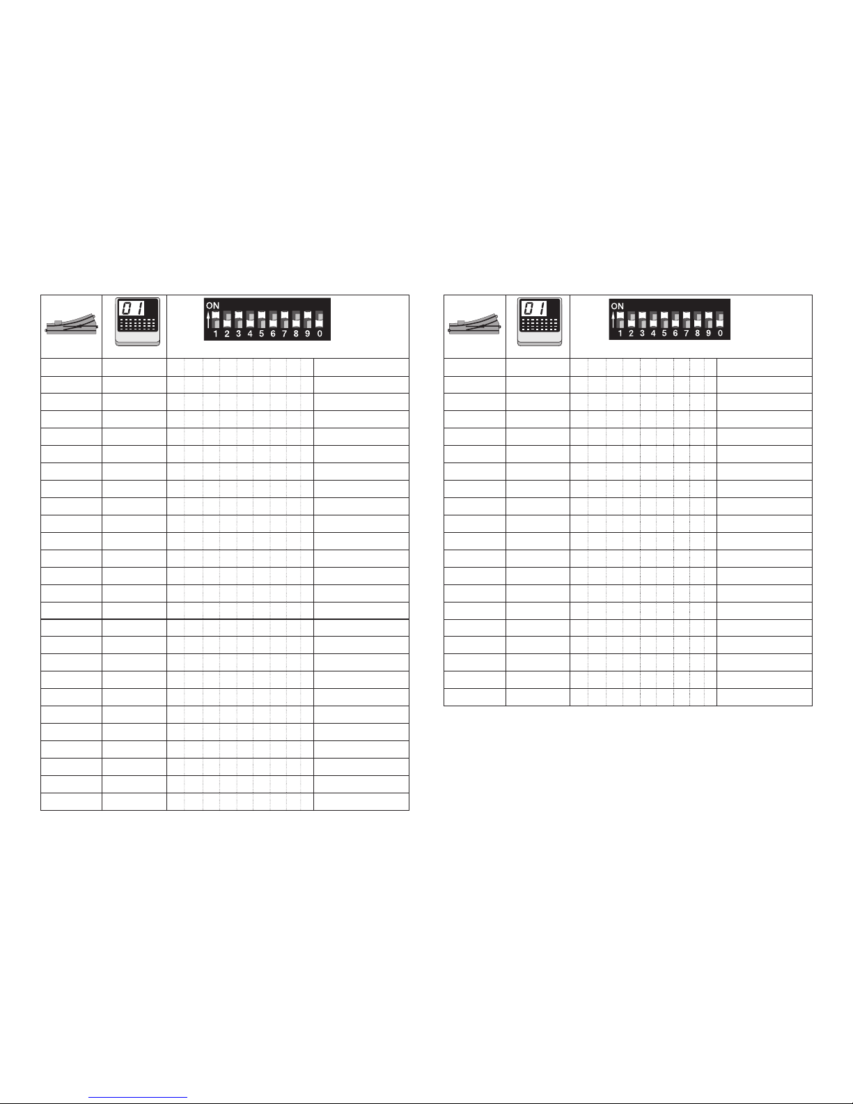
48
10 ( 0/1 )
466 30 2 2 5 7 8 9 - - - / DCC
467 30 3 1 2 5 7 8 9 - - - / DCC
468 30 4 3 5 7 8 9 - - - / DCC
469 30 5 1 3 5 7 8 9 - - - / DCC
470 30 6 2 3 5 7 8 9 - - - / DCC
471 30 7 1 2 3 5 7 8 9 - - - / DCC
472 30 8 4 5 7 8 9 - - - / DCC
473 30 9 1 4 5 7 8 9 - - - / DCC
474 30 10 2 4 5 7 8 9 - - - / DCC
475 30 11 1 2 4 5 7 8 9 - - - / DCC
476 30 12 3 4 5 7 8 9 - - - / DCC
477 30 13 1 3 4 5 7 8 9 - - - / DCC
478 30 14 2 3 4 5 7 8 9 - - - / DCC
479 30 15 1 2 3 4 5 7 8 9 - - - / DCC
480 30 16 6 7 8 9 - - - / DCC
481 31 1 1 6 7 8 9 - - - / DCC
482 31 2 2 6 7 8 9 - - - / DCC
483 31 3 1 2 6 7 8 9 - - - / DCC
484 31 4 3 6 7 8 9 - - - / DCC
485 31 5 1 3 6 7 8 9 - - - / DCC
486 31 6 2 3 6 7 8 9 - - - / DCC
487 31 7 1 2 3 6 7 8 9 - - - / DCC
488 31 8 4 6 7 8 9 - - - / DCC
489 31 9 1 4 6 7 8 9 - - - / DCC
490 31 10 2 4 6 7 8 9 - - - / DCC
491 31 11 1 2 4 6 7 8 9 - - - / DCC
10 ( 0/1 )
492 31 12 3 4 6 7 8 9 - - - / DCC
493 31 13 1 3 4 6 7 8 9 - - - / DCC
494 31 14 2 3 4 6 7 8 9 - - - / DCC
495 31 15 1 2 3 4 6 7 8 9 - - - / DCC
496 31 16 5 6 7 8 9 - - - / DCC
497 32 1 1 5 6 7 8 9 - - - / DCC
498 32 2 2 5 6 7 8 9 - - - / DCC
499 32 3 1 2 5 6 7 8 9 - - - / DCC
500 32 4 3 5 6 7 8 9 - - - / DCC
501 32 5 1 3 5 6 7 8 9 - - - / DCC
502 32 6 2 3 5 6 7 8 9 - - - / DCC
503 32 7 1 2 3 5 6 7 8 9 - - - / DCC
504 32 8 4 5 6 7 8 9 - - - / DCC
505 32 9 1 4 5 6 7 8 9 - - - / DCC
506 32 10 2 4 5 6 7 8 9 - - - / DCC
507 32 11 1 2 4 5 6 7 8 9 - - - / DCC
508 32 12 3 4 5 6 7 8 9 - - - / DCC
509 32 13 1 3 4 5 6 7 8 9 - - - / DCC
510 32 14 2 3 4 5 6 7 8 9 - - - / DCC
511 32 15 1 2 3 4 5 6 7 8 9 - - - / DCC
keyboard
keyboard
Page 49
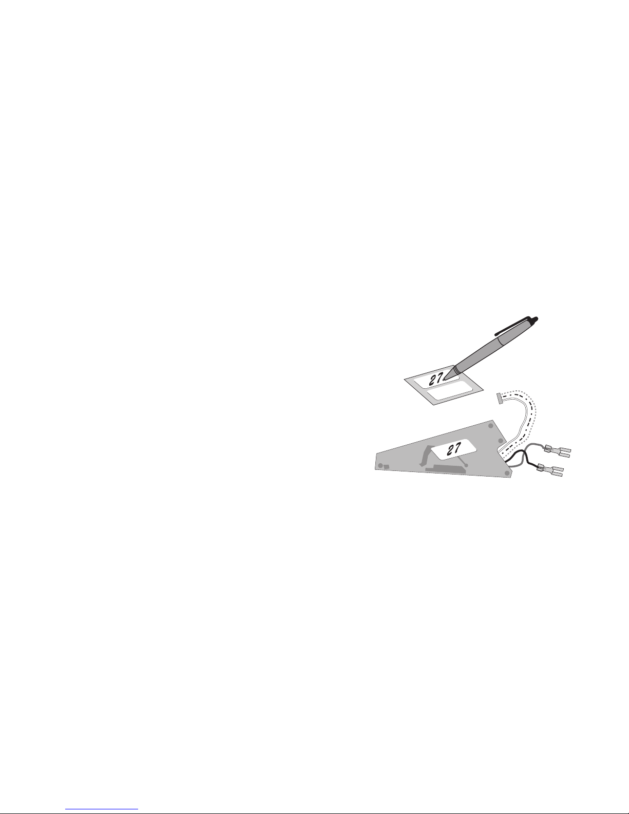
49
Adressen größer 511 können nur im DCC Format ausgegeben
werden und müssen mit der CV Programmierung über das
Programmiergleis durchgeführt werden.
Addresses larger than 511 can only be assigned in the DCC
format and must be done by programming a CV using the
programming track.
Les adresses supérieures à 511 peuvent uniquement être éditées
dans le format DCC et doivent être exécutées avec la programmation des CV via la voie de programmation.
Adressen groter dan 511 kunnen alleen in het DCC formaat
gebruikt worden en moeten met de CV programmering via het
programmeerspoor ingesteld worden.
Las direcciones superiores a 511 pueden mostrarse en el
formato DCC y deben configurarse con la función Programación
de CVs mediante la vía de programación.
Indirizzi maggiori di 511 possono essere assegnati solo nel
formato DCC e si devono eseguire con la programmazione delle
CV tramite il binario di programmazione.
Adresser överstigande 511 kan endast skrivas in i DCC-format
och måste göras med CV-programmering med loket på programmeringsspåret.
Adresser højere end 511 kan kun udtrykkes i DCC format og skal
udføres med CV programmeringen via programmeringssporet.
Adresse notieren
Noting the address
Noter l’adresse
Adres noteren
Anotar la dirección
Annotate gli indirizzi
Notera adressen
Notér adresser
Page 50

Page 51

Page 52
327187/1118/Sc1Kt
Änderungen vorbehalten
© Gebr. Märklin & Cie. GmbH
Gebr. Märklin & Cie. GmbH
Stuttgarter Straße 55 - 57
73033 Göppingen
Germany
www.maerklin.com www.maerklin.com/en/imprint.html
Due to different legal requirements regarding electro-magnetic compatibility,
this item may be used in the USA only after separate certification for FCC compliance and an adjustment if necessary.
Use in the USA without this certification is not permitted and absolves us of any
liability. If you should want such certification to be done, please contact us –
also due to the additional costs incurred for this.
 Loading...