

Page 1
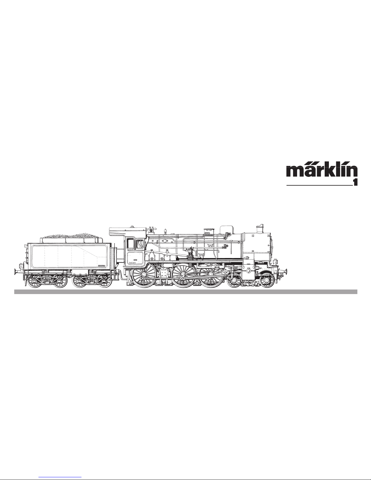
Serie 64 (pr. P 8)
Page 2

Page 3

2
Betrieb Seite 9 Operation Page 16 Fonctionnement Page 23 Exploitatie Blz. 30
1
Exploitation
Vorbild Seite 4 Prototype Page 6 dans le réel Page 7 Grootbedrijf Blz. 8
3
Betrieb auf Operation Exploitation Bedrijf op
einer Anlage Seite 37 on a layout Page 38 sur reseau Page 39 een modelbaan Blz. 40
4
Wartung Seite 41 Maintenance Page 41 Entretien Page 41 Onderhoud Blz. 41
3
Page 4
4
1
Vorbild
Page 5

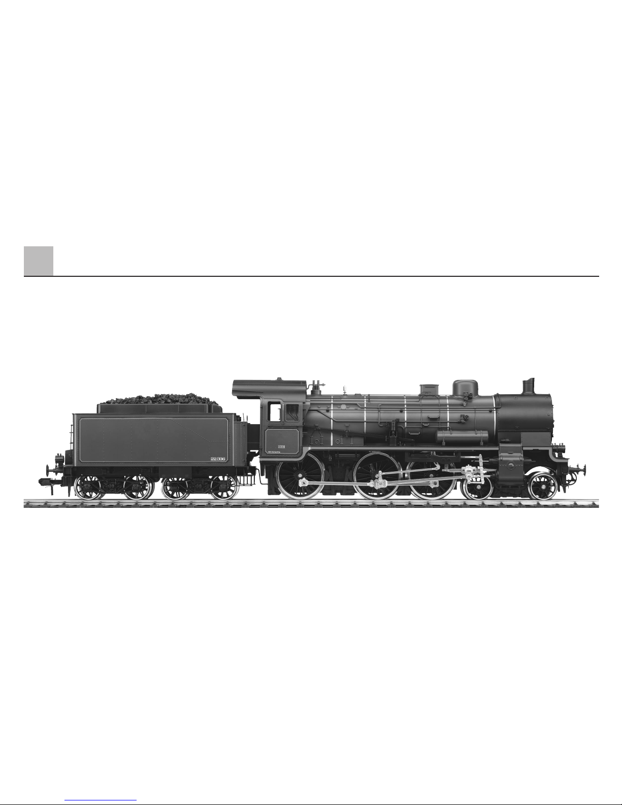
Serie 64 (pr. P 8)
Die Personenzuglokomotive der Bauart 2’C h2 war das Meisterwerk des
Lokomotivdezernenten der Preußischen Staatseisenbahnen Robert Garbe.
Von verschiedenen deutschen Fabriken wurden 3 726 Lokomotiven der
Gattung P8 gebaut. Allein die Preußischen Staatseisenbahnen und die
Deutsche Reichsbahngesellschaft beschafften zwischen 1906 und 1923
insgesamt 3 438 Lokomotiven. Der Rest gelangte zu anderen Länderbahnen
und an ausländische Bahnverwaltungen. 222 Exemplare bauten rumänische
Lokomotivfabriken nach.
Die P 8 war ein „Mädchen für Alles“ und beim Personal beliebt. Sie zog nicht
nur Personenzüge, sondern gelegentlich auch Schnell- und Güterzüge.
Die Maschinen waren nicht nur in Deutschland, sondern – bedingt durch die
beiden Weltkriege – fast in ganz Europa anzutreffen.
Die Maschinen dieses Typs, die nach Belgien gelangten, wurden von der
SNCB als Serie 64 eingereiht und den Erfordernissen an den belgischen
Bahnbetrieb angepasst. Auch die komplette äußere Gestaltung erfolgte
nach dem eigenen Farbschema und wurde den unterschiedlichen Vorgaben
während der langen Dienstzeit dieses Loktyps immer wieder angepasst.
Die Lok 64.045 blieb als Museumslok erhalten.
Technische Daten:
Bauart: 2‘C h2
Treib- und Kuppelrad-Ø: 1 750 mm
Laufrad-Ø: 1 000 mm
Länge über Puffer (mit Tender pr 2‘2‘ T 21,5): 18 592 mm
Höchstgeschwindigkeit vorwärts: 100 km/h
Höchstgeschwindigkeit rückwärts: 50 km/h
Leistung: 870 kW
1
5
Vorbild
Page 6

Class 64 (Prussian P 8)
This passenger locomotive with design 2’C h2 (4–6–0) was the masterpiece
of Robert Garbe, the head of the Locomotive Department of the Prussian
State Railways. 3,726 P8’s were built by various German companies.
The Prussian State Railways and the German State Railway together acquired
all total 3,438 locomotives between 1906 and 1923. The rest went to other
German railways and to foreign lines. 222 units were manufactured by
Romanian locomotive builders.
The P8 was a jack-of-all-trades and was a favorite with crews. It pulled not
only passenger trains, but also express and freight trains on occasion. As a
result of both world wars, these locomotives could be seen all over in Europe
as well as in Germany.
Locomotives of this class that ended up in Belgium were designated by the
SNCB as the class 64 and were adapted to the needs of Belgian railroad
operations. The painting and lettering for these locomotives followed Belgian
practice and was changed during the long service life of the locomotives to
meet the new railroad specifications. Locomotive no. 64.045 remains preserved
as a museum locomotive.
Technical Data:
Design: 4-6-0
Driving wheel dia.: 1,750 mm / 68-7/8”
Pilot wheel dia.: 1,000 mm / 39-3/8”
Length over buffers: 18,592 mm / 60’ 11-15/16”
(with type pr 2‘2‘ T 21,5 tender)
Maximum speed forwards: 100 km/h / 62.5 mph
Maximum speed in reverse: 50 km/h / 31 mph
Power: 870 kW / 1,166 hp
6
1
Prototype
Page 7

7
1
Exploitation dans le réel
Série 64 (pr. P 8)
Cette locomotive pour trains de voyageurs, du type 230, était le chef d’oeuvre
de Robert Garbe. Diverses fabriques de locomotives allemandes ont livré
en tout 3728 locos P8. Les chemins de fer prussiens et la Deutsche Reichsbahngesellschaft en ont acheté, entre 1906 et 1923 3438 exemplaires. Le
reste a été livré à d’autres Länderbahnen ainsi qu’à des compagnies étrangères. Des fabriques de locos roumaines en ont construit de leur côte 222.
La P8 était vraiment une bonne à tout faire, très estimée du personnel.
Elle a assuré les services omnibus, mais occasionnellement elle tirait également
des trains express ou des trains de marchandises. Par suite des deux guerres
mondiales, on a pu rencontrer ces machines dans tous les pays d’Europe.
Les machines de ce type parvenues en Belgique ont été reprises en écritures
par la SNCB dans la série 64 et adaptées aux conditions d'exploitation en
vigueur dans cette société. Durant leur longue carrière, ces locomotives ont
connu diverses livrées propres à la SNCB en fonction des exigences du
moment. La locomotive 64.045 a été préservée dans un musée ferroviaire.
Données techniques:
Disposition d'essieux: 2‘C h2
Ø roue motrice accouplée: 1 750 mm
Ø roue porteuse: 1 000 mm
Longueur hors tampons: 18 592 mm
(avec tender pr 2‘2‘ T 21,5)
Vitesse maximale en avant: 100 km/h
Vitesse maximale en arrière: 50 km/h
Puissance: 870 kW
Page 8

8
1
Grootbedrijf
Serie 64 (pr. P 8)
De personentreinlocomotief van het type 2’C h2 was het meesterwerk van
de afdelingschef locomotieven bij de Preussische Staatseisenbahnen Robert
Garbe. Door meerdere Duitse fabrieken werden 3726 locomotieven van het
type P8 gebouwd. Alleen al de Preussische Staatseisenbahnen en de Deutsche
Reichsbahngesellschaft schaften tussen 1906 en 1923 in totaal 3438 locomotieven aan. De rest bereikte andere regionale spoorwegmaatschappijen
en buitenlandse directies. Door Roemeense locomotieffabrieken werden
222 exemplaren nagebouwd.
De P8 was een meisje voor alles en was bij het personeel geliefd. Ze trok niet
alleen personentreinen, maar bij gelegenheid ook snel- en goederentreinen.
De machines waren niet alleen in Duitsland, maar – vanwege de beide wereldoorlogen – in bijna geheel Europa aan te treffen.
De machines van dit type die in België terecht kwamen, werden door de SNCB
als serie 64 bestempeld en aan de behoeften van het Belgische spoorwegbedrijf aangepast. Ook de gehele vormgeving van de locs gebeurde volgens
eigen kleurstelling, welke gedurende de lange tijd dat deze locs in dienst
waren voortdurend aangepast werd aan de geldende normen. De loc 64.045
bleef behouden als museumloc.
Technische gegevens:
Type: 2'C h2
Drijf- en koppelwiel Ø: 1 750 mm
Loopwiel Ø: 1 000 mm
Lengte over de buffers (met tender pr 2'2' T 21,5): 18 592 mm
Maximumsnelheid voorwaarts: 100 km/h
Maximumsnelheid achterwaarts: 50 km/h
Vermogen: 870 kW
Page 9

9
Betrieb
2.1 Funktion
Diese Lok mit eingebauter
Digital-Elektronik bietet:
● Wahlweise folgende Betriebsarten:
I. Konventioneller Wechsel-
spannungsbetrieb z.B. mit dem
Transformer 32 VA
II. Konventioneller Gleichspan-
nungsbetrieb (max. 18 V=)
III. Mehrzugbetrieb mit dem
Märklin DELTA System
(nur mit der DELTA Station 6607)
IV. Mehrzugbetrieb mit dem
Märklin Digital System
(nur Control Unit 6021)
Ein Betrieb mit anderen Systemen
wie z.B. Impulsbreitensteuerung oder
der früheren Märklin Zentraleinheit
Central Control 1 (Nr. 6030) ist nicht
möglich.
● Automatische Erkennung zwischen
konventionellem und Digital- /
DELTA-Betrieb. Die Auswahl
zwischen Wechselspannung und
Gleichspannung beim konventionellen Betrieb wird manuell auf
der Platine oder am Betriebsartenschalter an der Tenderunterseite
eingestellt.
● 80 Digital- (4 DELTA-) Adressen
über Codierschalter einstellbar.
Eingestellte Adresse ab Werk: 45
● Einstellbare Höchstgeschwindigkeit.
● Einstellbare Anfahr- / Bremsver-
zögerung. Bremsverzögerung im
konventionellen Betrieb systembedingt nicht wirksam.
● Fahrtrichtungsabhängige Spitzen-
beleuchtung im Digital-Betrieb
ein- / ausschaltbar. Bei konventionellem Betrieb ist die Intensität der
Beleuchtung geschwindigkeitsabhängig. Bei Betrieb mit DELTA
Station ist die Spitzenbeleuchtung
dauernd eingeschaltet.
● Nur im Betrieb mit Digital / DELTA:
manuell einschaltbares DampflokGeräuschmodul.
● Eingebauter Rauchgenerator, im
Digital-Betrieb mit Control Unit 6021
auch ausschaltbar.
● Mit dem Rauchgenerator wird
parallel dazu auch die Führer-
standsbeleuchtung eingeschaltet.
● Nur im Betrieb mit der Control Unit
6021: Schaltbares Geräusch einer
Lokpfeife.
● Nur im Betrieb mit der Control Unit
6021: Minimierung der eingestellten
Anfahr-/Bremsverzögerung über
Schaltfunktion.
● Vorne mit montierter Schrauben-
kupplung, hinten mit montierter
Klauenkupplung. Für beide Seiten
liegen Austauschkupplungen bei.
● Befahrbarer Mindestradius:
1020 mm. Dieser Radius ist nur
befahrbar, wenn die angehängten
Wagen an der Märklin Klauenkupplung gekuppelt sind.
● Das Modell ist für den Betrieb auf
dem Märklin Profi 1-Gleissystem
entwickelt. Ein Betrieb auf anderen
Gleissystemen geschieht auf
eigenes Risiko.
2
Page 10
Betrieb
10
2
2.2 Wahl der Versorgungsspannung
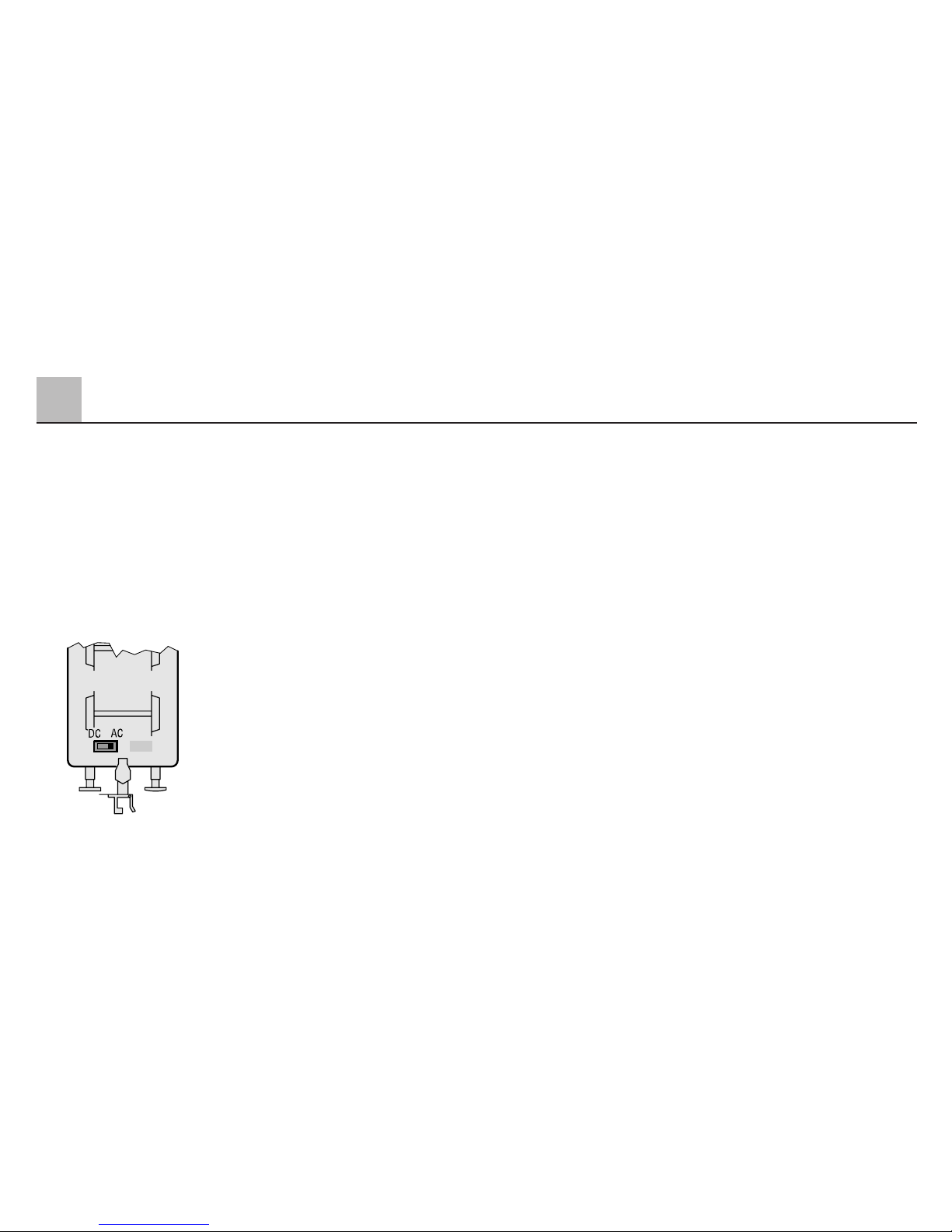
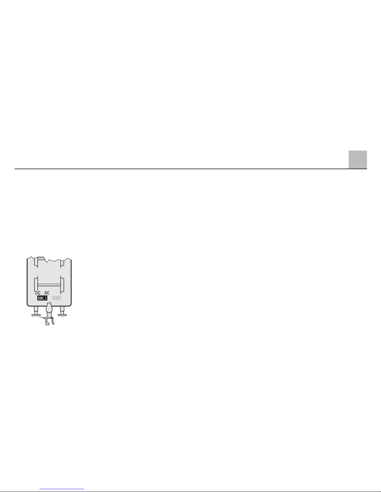
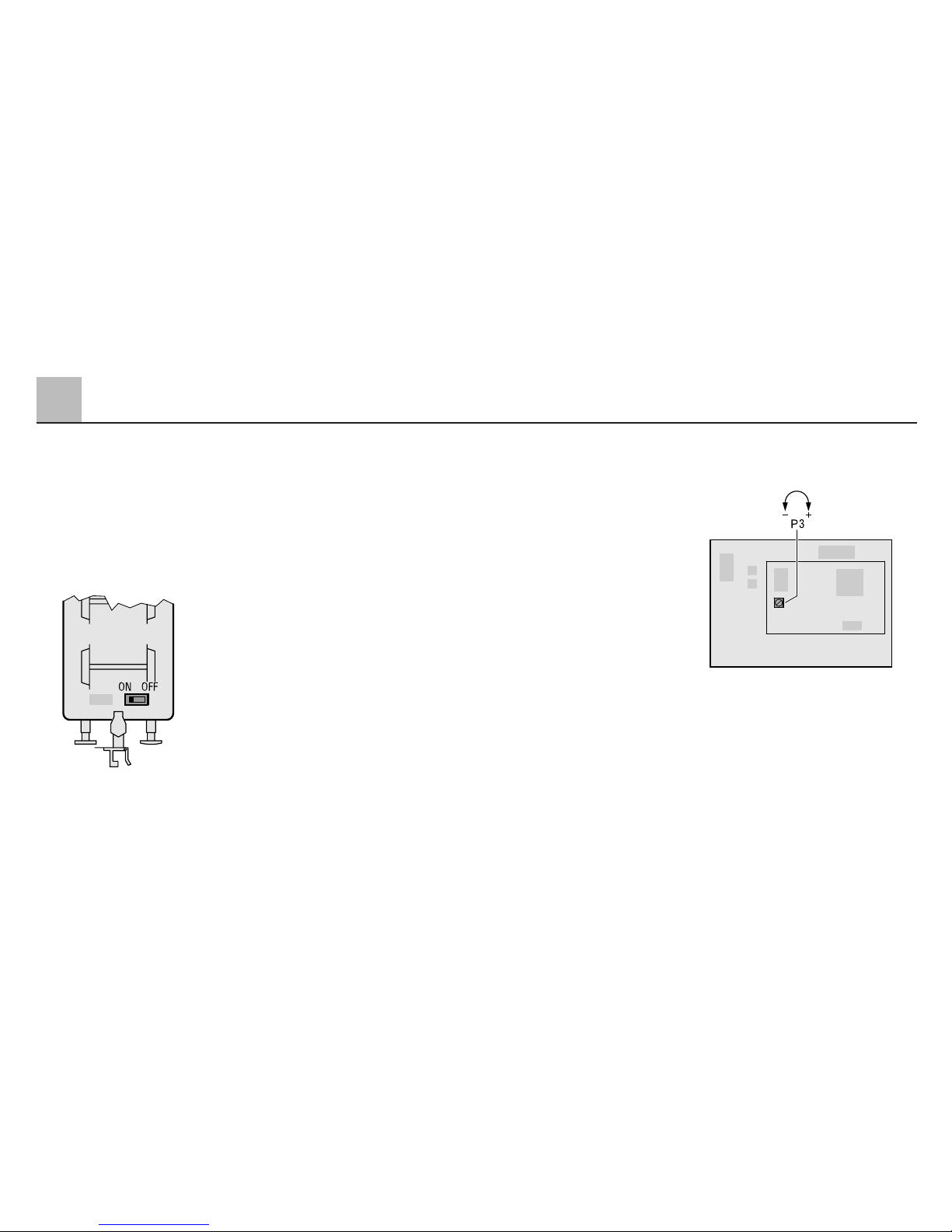
Der Schalter für die Betriebsart
Wechselstrom oder Gleichstrom
befindet sich unter dem Tender.
Stellung links: Gleichstrom
Stellung rechts: Wechselstrom
Die Betriebsart Digital/DELTA wird
immer automatisch erkannt.
Hinweis:
● Der Schalter 10 (Bezeichnung 0)
am Adressschalter der DigitalElektronik muss auf jeden Fall in
Stellung „off“ stehen. Ansonsten
ist der nach außen geführte
Betriebsartenschalter wirkungslos
und die Lok befindet sich dauernd
in der Betriebsart „Gleichstrom“
● In der Betriebsart „Gleichstrom“
und „Wechselstrom“ sind nur
Fahrgeräte verwendbar, die einen
geglätteten Gleichstrom oder einen
sinusförmigen Wechselstrom
erzeugen. Fahrgeräte mit Impulsbreitensteuerung sind nicht geeignet.
● Ab Werk ist bei dieser Lok die
Betriebsart „Wechselstrom“ eingestellt.
2.3 Einstellen der Höchstgeschwindigkeit und der Anfahr- und Bremsverzögerung
Zum Verändern der Höchstgeschwindigkeit oder der Anfahr- und
Bremsverzögerung muss zuerst das
Tendergehäuse abgenommen werden
(siehe Seite 45).
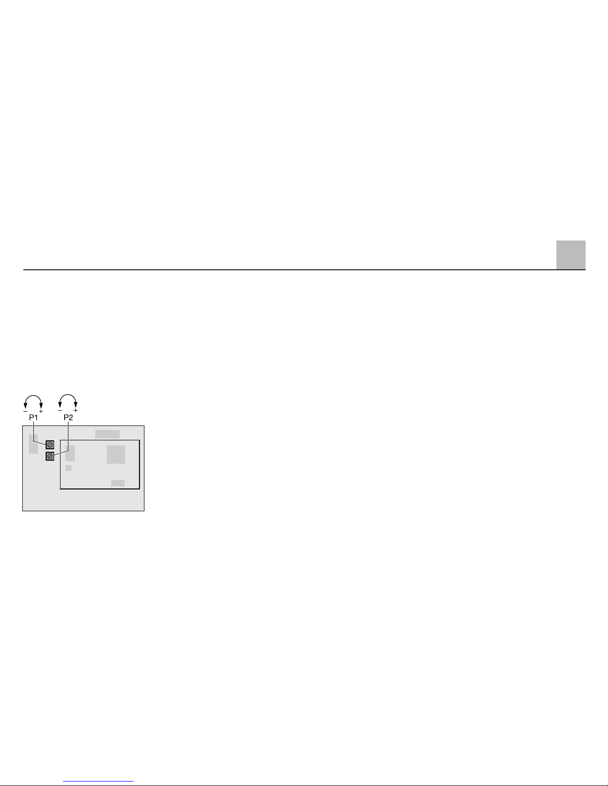
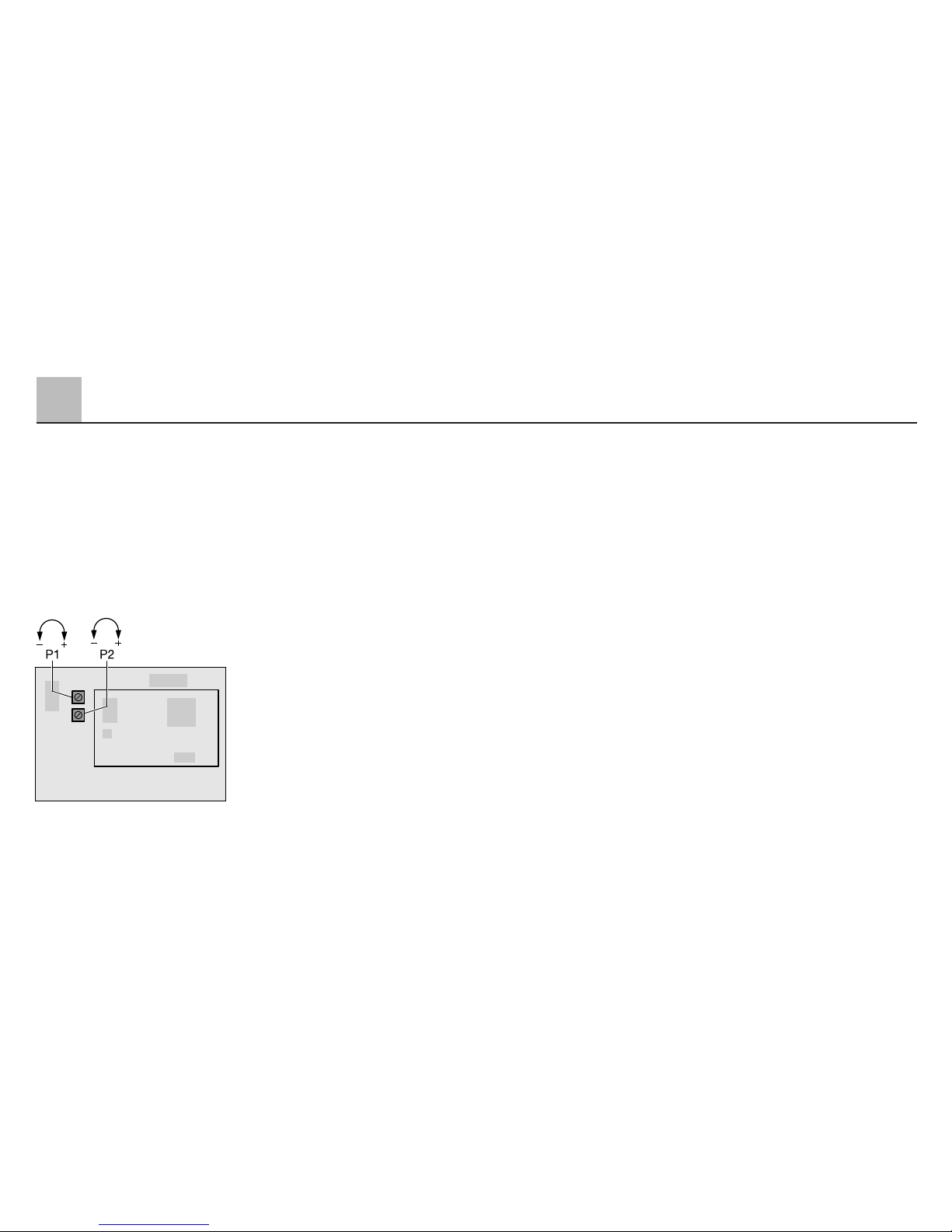
Auf der Elektronik-Platine befinden
sich zwei Drehpotentiometer, mit
denen die Anfahr- und Bremsverzö-
gerung oder die Höchstgeschwindigkeit der Lok verändert werden können.
Die Bremsverzögerung ist nur bei
Digital-Betrieb wirksam.
Drehpoti 1 (P 1):
Anfahr- und Bremsverzögerung
werden gemeinsam verändert.
Linksanschlag: minimale
Verzögerung
Rechtsanschlag: maximale
Verzögerung
Drehpoti 2 (P 2):
Einstellung der Höchstgeschwindigkeit
Linksanschlag: minimale Höchst-
geschwindigkeit
Rechtsanschlag: maximale Höchst-
geschwindigkeit
Ab Werk ist die maximale Höchstgeschwindigkeit und die mittlere Anfahrund Bremsverzögerung eingestellt.
Die lastabhängige Regelung der
Geschwindigkeit ist automatisch
wirksam. Technisch bedingt ist diese
Regelung in der Betriebsstellung
„Wechselstrom“ oder „Gleichstrom“
nicht so ausgeprägt wirksam wie in
der Stellung „Digital“.
Page 11
Im Digitalbetrieb mit der Control Unit
6021 kann durch Schalten der Funktion „f4“ die eingestellte Anfahr- und
Bremsverzögerung minimiert werden.
Dies ist zum Beispiel beim Rangieren
ein Vorteil, wenn man die Lok im
direkten Zugriff haben möchte.
2.4 Betrieb bei den einzelnen
Versorgungs-Systemen
2.4.1 Digital/DELTA
Zur Steuerung kann die Control Unit
(6021) verwendet werden. Auf der
Rückseite der Control Unit befinden
sich vier Codierschalter, die für den
Betrieb mit Märklin 1-Fahrzeugen in
folgende Stellung gebracht werden:
Schalter
12 34
on on on off
Die Schalter dürfen nur bei ausgeschalteter Control Unit verändert
werden. Durch diese Schalter wird
zum Beispiel die Fahrtrichtungsanzeige in der Control Unit aktiviert.
Bei der Verwendung der Central Unit
6020 können die vier Zusatzfunktionen f1 bis f4
nicht angesprochen
werden. Ebenso entfällt bei dieser Zentraleinheit die Fahrtrichtungsangabe.
In der Stellung Digital kann diese Lok
auch mit der DELTA-Station über
einen Handregler DELTA-Mobil
gesteuert werden, wenn eine der vier
möglichen DELTA-Adressen am
Adress-Codierschalter eingestellt ist.
Beim Betrieb mit der DELTA-Station
ist die Lichtfunktion eingeschaltet.
2.4.1.1 Einstellen der Lokadresse
Zum Verändern der Lokadresse muss
zuerst das Tendergehäuse abgenommen werden (siehe Seite 45).
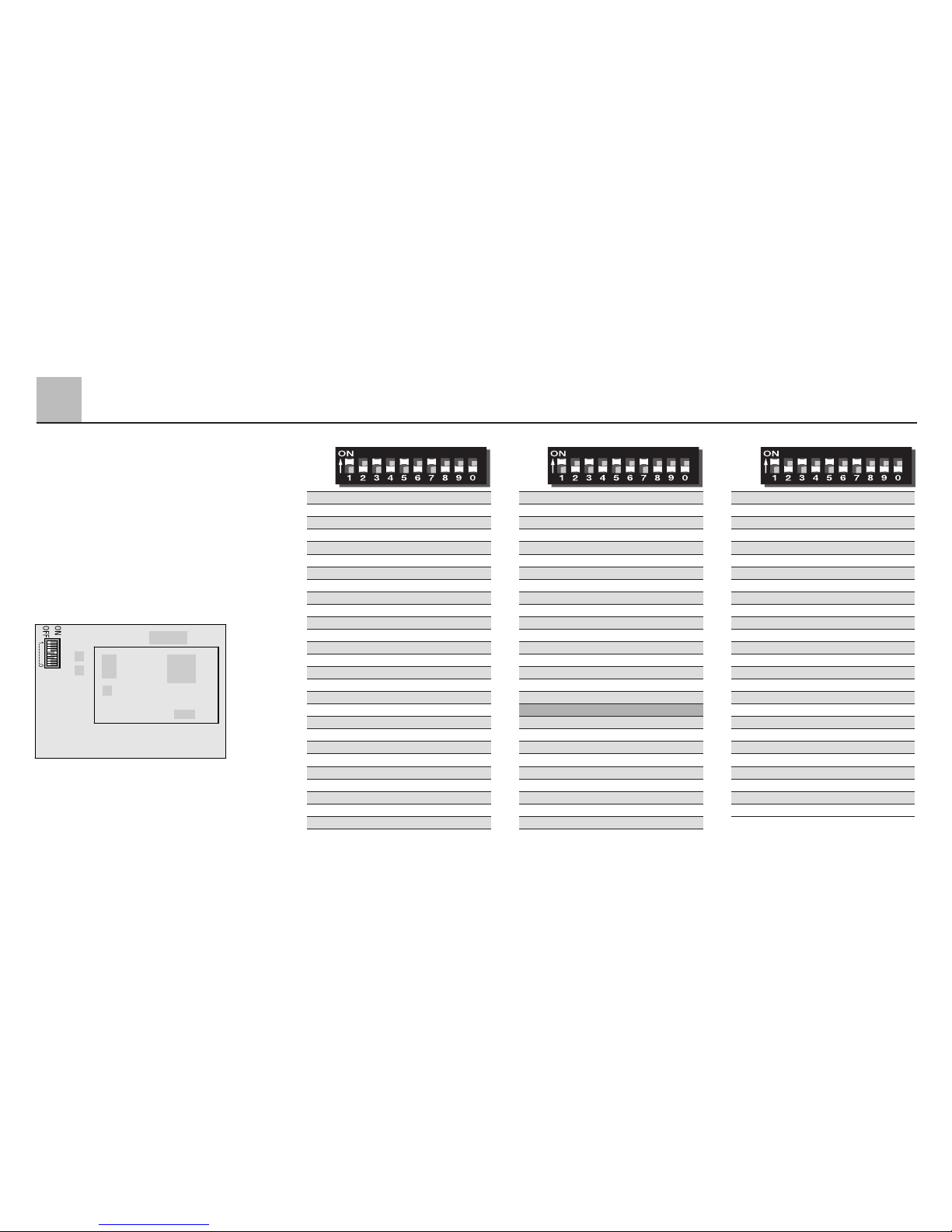
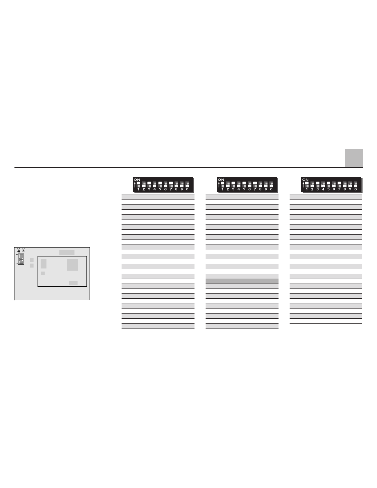
Die Digitaladresse der Lok wird mit
dem zehnstelligen Codierschalter auf
der Elektronik eingestellt. Ab Werk ist
die Adresse „45“ eingestellt. Die nachfolgende Tabelle zeigt die möglichen
Lokadressen zusammen mit den
zugehörigen Schalterstellungen an.
11
2
Betrieb
Page 12
12
Digital
Digital
Digital
28 – 2 3 – 5 – – 8 – –
29 – – 3 – 5 – – 8 – –
30 1 – – 4 5 – – 8 – –
31 – 2 – 4 5 – – 8 – –
32 – – – 4 5 – – 8 – –
33 1 – – – 5 – – 8 – –
34 – 2 – – 5 – – 8 – –
35 – – – – 5 – – 8 – –
36 1 – 3 – – 6 – 8 – –
37 – 2 3 – – 6 – 8 – –
38 – – 3 – – 6 – 8 – –
39 1 – – 4 – 6 – 8 – –
40 – 2 – 4 – 6 – 8 – –
41 – – – 4 – 6 – 8 – –
42 1 – – – – 6 – 8 – –
43 – 2 – – – 6 – 8 – –
44 – – – – – 6 – 8 – –
45 1 – 3 – – – – 8 – –
46 – 2 3 – – – – 8 – –
47 – – 3 – – – – 8 – –
48 1 – – 4 – – – 8 – –
49 – 2 – 4 – – – 8 – –
50 – – – 4 – – – 8 – –
51 1 – – – – – – 8 – –
52 – 2 – – – – – 8 – –
53 – – – – – – – 8 – –
54 1 – 3 – 5 – – – – –
55 – 2 3 – 5 – – – – –
56 – – 3 – 5 – – – – –
57 1 – – 4 5 – – – – –
58 – 2 – 4 5 – – – – –
59 – – – 4 5 – – – – –
60 1 – – – 5 – – – – –
61 – 2 – – 5 – – – – –
62 – – – – 5 – – – – –
63 1 – 3 – – 6 – – – –
64 – 2 3 – – 6 – – – –
65 – – 3 – – 6 – – – –
66 1 – – 4 – 6 – – – –
67 – 2 – 4 – 6 – – – –
68 – – – 4 – 6 – – – –
69 1 – – – – 6 – – – –
70 – 2 – – – 6 – – – –
71 – – – – – 6 – – – –
72 1 – 3 – – – – – – –
73 – 2 3 – – – – – – –
74 – – 3 – – – – – – –
75 1 – – 4 – – – – – –
76 – 2 – 4 – – – – – –
77 – – – 4 – – – – – –
78 1 – – – – – – – – –
79 – 2 – – – – – – – –
80 1 – 3 – 5 – 7 – – –
01 – 2 3 – 5 – 7 – – –
02 – – 3 – 5 – 7 – – –
03 1 – – 4 5 – 7 – – –
04 – 2 – 4 5 – 7 – – –
05 – – – 4 5 – 7 – – –
06 1 – – – 5 – 7 – – –
07 – 2 – – 5 – 7 – – –
08 – – – – 5 – 7 – – –
09 1 – 3 – – 6 7 – – –
10 – 2 3 – – 6 7 – – –
11 – – 3 – – 6 7 – – –
12 1 – – 4 – 6 7 – – –
13 – 2 – 4 – 6 7 – – –
14 – – – 4 – 6 7 – – –
15 1 – – – – 6 7 – – –
16 – 2 – – – 6 7 – – –
17 – – – – – 6 7 – – –
18 1 – 3 – – – 7 – – –
19 – 2 3 – – – 7 – – –
20 – – 3 – – – 7 – – –
21 1 – – 4 – – 7 – – –
22 – 2 – 4 – – 7 – – –
23 – – – 4 – – 7 – – –
24 1 – – – – – 7 – – –
25 – 2 – – – – 7 – – –
26 – – – – – – 7 – – –
27 1 – 3 – 5 – – 8 – –
Werden die Adressen 24, 60, 72,
oder 78 eingestellt, so kann die Lok
auch mit der DELTA-Station in Verbindung mit dem Handregler
DELTA-Mobil gesteuert werden.
Hinweis:
Die Schalter 9 + 10 (Bezeichnung „9“
und „0“) müssen immer in der
Stellung „off“ stehen.
Betrieb
2
Page 13

2.4.1.2 Fahren der Lok mit Digital
Zum Fahren der Lok mit Märklin
Digital wird die Lokadresse auf der
Control Unit (6021) oder einem angeschlossenen Fahrgerät Control 80 f
(6036) eingegeben. Durch Drehen
des Fahrreglers nach rechts wird die
Geschwindigkeit der Lok erhöht und
durch Drehen nach links wird sie
entsprechend vermindert. Wird der
Fahrregler über die Stellung „0“ nach
links weiter bewegt, so wird die
Fahrtrichtung umgeschaltet. Mit der
Taste „function“ kann die Beleuchtung
in der Lok fahrtrichtungsabhängig
eingeschaltet und mit der Taste „off“
wieder ausgeschaltet werden.
Über die Tasten „f1“ bis „f4“ können
folgende Funktionen eingeschaltet
werden:
f1 = Rauchgenerator und Führer-
standsbeleuchtung ein / aus
f2 = Glockengeräusch ein / aus
f3 = Pfeifengeräusch ein / aus
f4 = Anfahr- und Bremsverzögerung
minimieren (siehe 2.3)
Hinweis zur Funktionsbelegung:
Der Rauchgenerator darf ohne
Dampföl nicht längere Zeit eingeschaltet werden. Damit der Modellbahner erkennen kann, ob diese
Funktion eingeschaltet ist, wird daher
bei diesem Modell parallel auch die
Führerstandsbeleuchtung eingeschaltet.
Das Vorbild dieser Lokomotive
besitzt zwar keine Glocke. Da das
eingebaute Geräuschmodul jedoch
diese Funktion besitzt, wurde diese
vorhandene Funktion bei diesem
Modell auch schaltbar ausgeführt.
Wer vorbildgetreu fahren möchte sollte
auf das Auslösen der Funktion f2
verzichten. Wer ohne direkten Vorbildbezug das Modell betreibt kann
sich an dieser Funktion erfreuen.
Das eingebaute Betriebsgeräusch
kann manuell ein- und ausgeschaltet
werden (siehe 2.5). Es ist nur für den
Digital- oder DELTA-Betrieb vorgesehen.
2.4.2 Fahren der Lok mit DELTA
Zum Fahren der Lok mit Märklin
DELTA wird an dem Handregler
DELTA-Mobil die eingestellte Lokadresse angewählt. Durch Drehen
des Fahrreglers aus der Mittelstellung
heraus nach rechts fährt die Lok vorwärts. Durch Drehen des Fahrreglers
aus der Mittelstellung nach links fährt
die Lok rückwärts. Die fahrtrichtungsabhängige Beleuchtung ist dauernd
eingeschaltet. Die maximale Ausgangsleistung der DELTA-Station
reicht zum gleichzeitigen Fahren von
2 bis maximal 3 einmotorigen Lokomotiven.
Von den Funktionen f1 bis f4 ist im
Betrieb mit der DELTA-Station die
Funktion f1 immer eingeschaltet.
Die restlichen Funktionen sind immer
ausgeschaltet.
13
2
Betrieb
Page 14

2.4.3 Fahren mit Wechselspannung
In der Betriebsart „Wechselspannung“
kann die Lok z.B. mit dem Transformer 32 VA (Nr. 6645, 6646, 6647
oder 76648) gesteuert werden.
Durch Drehen des Fahrreglers nach
rechts wird die Geschwindigkeit der
Lok erhöht und durch Drehen nach
links wird sie entsprechend vermindert. Wird der Fahrregler über die
Stellung „0“ nach links weiter
gedreht, so wird die Fahrtrichtung
umgeschaltet. Der Umschaltbefehl
für die Fahrtrichtung sollte nie an eine
fahrende Lok sondern immer nur an
eine stehende Lok gegeben werden.
Im Betrieb mit Wechselspannung ist
die fahrtrichtungsabhängige Beleuchtung eingeschaltet. Die Intensität der
Beleuchtung ist geschwindigkeitsabhängig.
Von den Funktionen f1 bis f4 ist im
Betrieb die Funktion f1 immer eingeschaltet. Die restlichen Funktionen
sind immer ausgeschaltet.
2.4.4 Fahren mit Gleichspannung
Gleichspannungs-Fahrgeräte werden
von Märklin für Spur-1-Modelle nicht
angeboten. Geeignet sind Gleichspannungs-Fahrgeräte mit einer
maximalen Spannung von ±18 Volt.
Der Fahrtrichtungswechsel wird
durch einen Polaritätswechsel vorgenommen. Die Bedienung des jeweiligen Fahrgerätes entnehmen Sie der
Anleitung des Herstellers.
Hinweis:
H0-Gleichspannungs-Fahrgeräte
geben eine maximale Spannung von
±12 Volt ab. Die Lok erreicht jedoch
ihre volle Leistungsfähigkeit erst bei
±16 Volt. H0-Gleichspannungs-Fahrgeräte sind daher nur eingeschränkt
verwendbar. Im Betrieb mit Gleichspannung ist die fahrtrichtungsabhängige Beleuchtung eingeschaltet.
Die Intensität der Beleuchtung ist
geschwindigkeitsabhängig.
Von den Funktionen f1 bis f4 ist im
Betrieb die Funktion f1 immer eingeschaltet. Die restlichen Funktionen
sind immer ausgeschaltet.
14
2
Betrieb
Page 15
2.5 Die eingebaute
Geräuschelektronik
Die eingebaute Geräuschelektronik
gibt passend zum Fahrzustand der
Lok das Betriebsgeräusch einer
Dampflokomotive wieder. Diese
Geräuschelektronik kann über einen
Schalter am Tender ein- und ausgeschaltet werden.
Hinweis:
Da diese Geräuschelektronik eine
Mindestversorgungsspannung
benötigt, ist sie nur für den Betrieb
mit Märklin Digital oder DELTA vorgesehen. Beim Betrieb mit Wechseloder Gleichspannung wird die Elektronik erst im Fahrbetrieb ab einer
bestimmten Geschwindigkeit zu
hören sein. Durch Störungen kann es
dabei auch zu einer fehlerhaften
Geräuschwiedergabe kommen.
Daher empfehlen wir die Geräusch-
elektronik nur bei Märklin Digitaloder DELTA-Betrieb zu verwenden.
2.5.1 Einstellen der Lautstärke
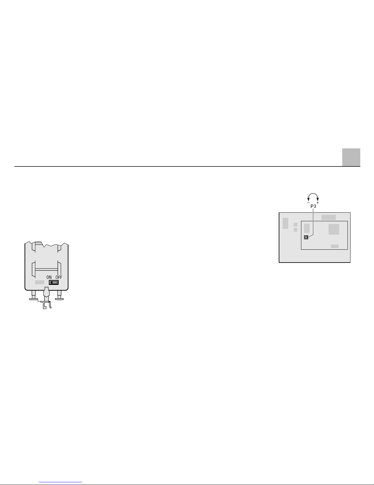
Auf der Geräuschplatine kann über
ein Poti (P3) die Gesamtlautstärke
reguliert werden. Entfernen Sie hierzu
das Tendergehäuse (siehe Seite 45).
Wichtiger Hinweis:
Neben dem Poti für die Lautstärke
befindet sich ein 8-fach Codierschalter
auf der Geräuschplatine. Mit diesen
Codierschaltern wird die Geräuschelektronik werksseitig optimal auf Ihre
Lokomotive abgestimmt. Verändern
Sie daher nie die Einstellung dieser
Codierschalter!
2
15
Betrieb
Page 16

16
2
Operation
2.1 Function
This locomotive has a built-in digital
electronic circuit and offers the following features:
● The following modes of operation
are possible with this model:
I. Conventional AC power
operation, example:
with a 32 VA transformer
II. Conventional DC power
operation (max. 18 volts DC)
III. Multi-train operation with the
Märklin DELTA system (only
with the 6607 DELTA Station)
IV. Multi-train operation with the
Märklin Digital system (only with
the 6021 Control Unit 6021)
This locomotive is not designed for
operation with other systems such as
pulse width control or the earlier Märklin
Central Control 1 Central Unit(no. 6030).
● Automatically recognizes conven-
tional and Digital / DELTA operation.
The choice between AC power
and DC power in conventional
operation is set manually on the
circuit board or on the switch for
the mode of operation on the
underside of the tender.
● 80 Digital (4 DELTA) addresses
can be set with coding switches.
Address set at the factory: 45
● Adjustable maximum speed.
● Adjustable acceleration/braking
delay. The electronic circuit for the
locomotive is designed in such a
way that the braking delay will not
work in conventional operation.
● Headlights change over with the
direction of travel and can be turned
on and off in Digital operation.
During conventional operation the
brightness of the headlights
depends on the speed of the locomotive. The headlights are on constantly when the locomotive is
operated with the DELTA Station.
● Only possible with operation with
Digital/DELTA: steam locomotive
sound effects module that can be
turned on manually.
● Built-in smoke generator, can also
be turned of in digital operation
with the 6021 Control Unit 6021.
● The lighting for the engineer’s cab
is turned on in parallel with the
smoke generator.
● Only possible with operation with
the 6021 Control Unit: Sound of a
locomotive whistle can be turned
on and off.
● Only in operation with the 6021
Control Unit: The acceleration /
braking delay can be reduced to a
minimum with one of the auxiliary
function buttons.
● Reproduction prototype coupler
mounted on the front, claw coupler mounted on the rear. Replacement couplers are included for
both ends of the locomotive.
● Minimum radius required for ope-
ration: 1,020 mm / 40-5/32". This
radius can be negotiated by the
train only when the locomotive is
coupled to the cars be means of
the Märklin claw coupler.
● This model was designed for ope-
ration on the Märklin standard 1
Gauge track system. You incur
your own risk operating it on other
track systems.
Page 17
2.2 Selecting the voltage
for power
The switch for the AC or DC power
mode of operation is located under
the tender.
Left setting: DC power
Right setting: AC power
The Digital/DELTA mode of operation
is always recognized automatically.
Tip:
● Switch 10 (designated 0) of the
address switches on the digital
electronic circuit must always be
set at off. Otherwise the mode of
operation switch on the bottom of
the tender will not work and the
locomotive will be set continuously
for the “DC power” mode of operation.
● Only locomotive controllers that
produce a smoothed DC power or
a sine wave AC power can be used
in the “DC power” and “AC power”
mode of operation. Locomotive
controllers with pulse width control
are not suitable for this model.
● The locomotive is delivered from
the factory set for the “AC power”
mode of operation.
2.3 Setting the maximum
speed and the acceleration
and braking delay
The tender body must first be removed
to change the maximum speed or
the acceleration and braking delay
(see page 45).
There are two potentiometers on the
electronic circuit plate which are
used to change the locomotive’s
maximum speed or acceleration and
braking delay. The braking delay
works only with digital operation.
Potentiometer 1 (P 1):
Acceleration and braking delay are
changed at the same time.
Turning to the left: minimum delay
Turning to the right: maximum delay
Potentiometer 2 (P 2):
Setting for maximum speed
Turning to the left: lowest maxi-
mum speed
Turning to the right: highest maxi-
mum speed
The highest maximum speed and
a medium acceleration and braking
delay are set at the factory.
The load-dependent speed control
functions automatically. Technically
this control is more apparent in the
“digital“ operation setting than in the
settings “AC power“ or “DC power“.
2
17
Operation
Page 18
In digital operation with the 6021
Control Unit the “f4” function can be
used to minimize the acceleration
and braking delay that has been set.
This is an advantage when switching
cars, for example, when you want to
have direct control over the locomotive.
2.4 Operation with the various
power systems
2.4.1 Digital/DELTA
The Control Unit (6021) can be used
for control. There are 4 coding switches on the back of the Control Unit
which are to be set as follows for
operation with Märklin 1 locomotives:
Switch
12 34
on on on off
These switch settings are to be
changed only when the Control Unit
is off. The direction indicator on the
Control Unit is activated by these
switches.
The 4 auxiliary switches f 1 to f 4
can-
not
be addressed when using the
6020 Central Unit. The direction indicator is likewise not present with this
central unit.
When set for Digital, this locomotive
can also be used with the DELTAStation and a DELTA-Mobil hand
controller; the four coding switches
on the locomotive must be set for
one of the four DELTA addresses.
The headlight auxiliary function is
turned on when operating with the
DELTA-Station.
2.4.1.1 Setting the locomotive
address
The tender body must first be removed to change the locomotive’s
address (see page 45).
The locomotive’s digital address is set
with the ten coding switches on the
electronic circuit. The address “45”
has been set at the factory. The following table shows the possible locomotive addresses together with the
appropriate switch settings for them.
18
2
Operation
Page 19
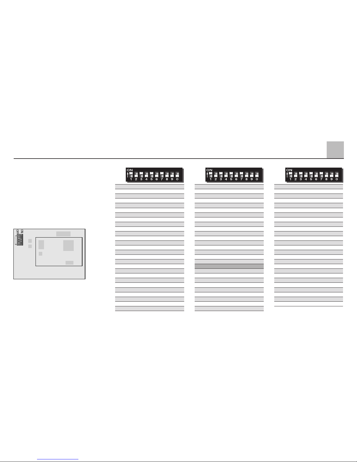
2
19
Operation
When the addresses 24, 60, 72 or 78
are set, then the locomotive can also
be controlled with the DELTA-Station
in conjunction with the DELTA-Mobil
hand controller.
Tip:
Switches 9 + 10 (designation “9”
and “0”) must always be set at “off”.
Digital
Digital
Digital
01 – 2 3 – 5 – 7 – – –
02 – – 3 – 5 – 7 – – –
03 1 – – 4 5 – 7 – – –
04 – 2 – 4 5 – 7 – – –
05 – – – 4 5 – 7 – – –
06 1 – – – 5 – 7 – – –
07 – 2 – – 5 – 7 – – –
08 – – – – 5 – 7 – – –
09 1 – 3 – – 6 7 – – –
10 – 2 3 – – 6 7 – – –
11 – – 3 – – 6 7 – – –
12 1 – – 4 – 6 7 – – –
13 – 2 – 4 – 6 7 – – –
14 – – – 4 – 6 7 – – –
15 1 – – – – 6 7 – – –
16 – 2 – – – 6 7 – – –
17 – – – – – 6 7 – – –
18 1 – 3 – – – 7 – – –
19 – 2 3 – – – 7 – – –
20 – – 3 – – – 7 – – –
21 1 – – 4 – – 7 – – –
22 – 2 – 4 – – 7 – – –
23 – – – 4 – – 7 – – –
24 1 – – – – – 7 – – –
25 – 2 – – – – 7 – – –
26 – – – – – – 7 – – –
27 1 – 3 – 5 – – 8 – –
28 – 2 3 – 5 – – 8 – –
29 – – 3 – 5 – – 8 – –
30 1 – – 4 5 – – 8 – –
31 – 2 – 4 5 – – 8 – –
32 – – – 4 5 – – 8 – –
33 1 – – – 5 – – 8 – –
34 – 2 – – 5 – – 8 – –
35 – – – – 5 – – 8 – –
36 1 – 3 – – 6 – 8 – –
37 – 2 3 – – 6 – 8 – –
38 – – 3 – – 6 – 8 – –
39 1 – – 4 – 6 – 8 – –
40 – 2 – 4 – 6 – 8 – –
41 – – – 4 – 6 – 8 – –
42 1 – – – – 6 – 8 – –
43 – 2 – – – 6 – 8 – –
44 – – – – – 6 – 8 – –
45 1 – 3 – – – – 8 – –
46 – 2 3 – – – – 8 – –
47 – – 3 – – – – 8 – –
48 1 – – 4 – – – 8 – –
49 – 2 – 4 – – – 8 – –
50 – – – 4 – – – 8 – –
51 1 – – – – – – 8 – –
52 – 2 – – – – – 8 – –
53 – – – – – – – 8 – –
54 1 – 3 – 5 – – – – –
55 – 2 3 – 5 – – – – –
56 – – 3 – 5 – – – – –
57 1 – – 4 5 – – – – –
58 – 2 – 4 5 – – – – –
59 – – – 4 5 – – – – –
60 1 – – – 5 – – – – –
61 – 2 – – 5 – – – – –
62 – – – – 5 – – – – –
63 1 – 3 – – 6 – – – –
64 – 2 3 – – 6 – – – –
65 – – 3 – – 6 – – – –
66 1 – – 4 – 6 – – – –
67 – 2 – 4 – 6 – – – –
68 – – – 4 – 6 – – – –
69 1 – – – – 6 – – – –
70 – 2 – – – 6 – – – –
71 – – – – – 6 – – – –
72 1 – 3 – – – – – – –
73 – 2 3 – – – – – – –
74 – – 3 – – – – – – –
75 1 – – 4 – – – – – –
76 – 2 – 4 – – – – – –
77 – – – 4 – – – – – –
78 1 – – – – – – – – –
79 – 2 – – – – – – – –
80 1 – 3 – 5 – 7 – – –
Page 20

2.4.1.2 Operating the locomotive
with Digital
To operate the locomotive with
Märklin Digital, the locomotive address
is entered on the Control Unit (6021)
or with a Control 80 f (6036) locomotive controller connected to it. The
locomotive’s speed is increased by
turning the speed control knob to the
right and is decreased by turning this
knob to the left. The direction of travel
is changed by turning the speed
control knob to the left past the “0“
setting. The locomotive’s headlights
can be turned on with the “function“
button and off with the “off“ button.
When turned on, the headlights are
on in the direction of travel.
The following functions can be controlled with the “f1” through “f4”
buttons:
f1 = Smoke generator and engineer’s
cab lighting on / off
f2 = Sound effects of locomotive bell
on / off
f3 = Sound effects of locomotive
whistle on / off
f4 = Minimum acceleration and
braking delay (see 2.3)
Information about the Functions:
The smoke generator must not be
left turned on for long periods of time
without any smoke fluid in it. The
engineer’s cab lighting comes on at
the same time as the smoke generator
so that the model railroader will know
that the latter function is turned on.
The prototype of this locomotive
does not have a bell. Since the
sound effects module built into the
model already has this function, this
existing function was wired in the
locomotive so that it could be turned
on and off. If you want to operate the
locomotive in a prototypical manner
should leave function f2 turned off.
If prototypical operation is not absolutely necessary for you, then you
can take advantage of the enjoyment
to be had from this function.
The built-in sound effects for the
operation of the locomotive can be
turned on and off manually (see 2.5).
It is designed for operation with
Digital or DELTA controls only.
2.4.2 Operating the locomotive
with DELTA
To operate the locomotive with Märklin
DELTA you use the DELTA-Mobil to
select the address that has been set
on the former. The locomotive will
run forward when you turn the speed
control knob to the right of the center
position. Turning the speed control
knob to the left of the center position
will cause the locomotive to run in
reverse. The headlights change
direction with the direction of travel
and are on all of the time. The maximum power output of the DELTAStation is sufficient to operate 2 to
a maximum of 3 single motor locomotives at the same time.
Of the functions f1 to f4, the function f1
is on continuously when operating the
locomotive with the DELTA Station.
The other functions remain off.
20
2
Operation
Page 21

2.4.3 Operating the locomotive
on alternating current
When the locomotive is operated with
AC power in conventional operation,
the 32 VA transformer (no. 6645,
6646, 6647 or 76648) can be used.
Locomotive speed is increased by
turning the control knob to the right
and is decreased by turning the knob
to the left. The direction of travel is
changed by turning the control knob
to the left past the “0” setting.
The command to reverse should be
given only to a standing locomotive,
never to one in motion.
In operation with alternating current
the headlights change direction with
the direction of travel and are on all
of the time. The intensity of the headlights depends on the speed of the
locomotive.
Of the functions f1 to f4, the function
f1 is on continuously when operating
the locomotive with conventional AC
power. The other functions remain off.
2.4.4 Operating the locomotive
on direct current
Märklin does not offer DC power
packs for 1 Gauge models. Suitable
DC power packs are those with a
maximum current of ±18 volts.
Direction reversing is done by reversing polarity. The manufacturer's
instructions for a particular make of
power pack will give directions on
how to use it to operate a locomotive.
Tip:
H0 DC power packs supply a maxi-
mum voltage of ±12 volts. This locomotive reaches its full potential at
±16 volts. H0 DC power packs can
therefore be used only with limitations.
In operation with direct current the
headlights change direction with the
direction of travel and are on all of
the time. The intensity of the headlights depends on the speed of the
locomotive.
Of the functions f1 to f4, the function
f1 is on continuously when operating
the locomotive with conventional DC
power. The other functions remain off.
2
21
Operation
Page 22
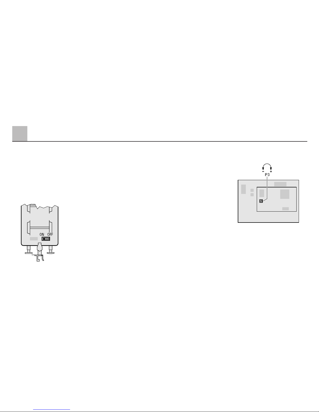
2.5 The Built-In Sound
Effects Circuit
The built-in sound effects circuit
reproduces the sounds of a steam
locomotive in operation, and these
sounds vary with the level of operation
the locomotive is at. This sound
effects circuit can be turned on and
off with a switch in the tender.
Important:
Since this sound effects circuit re-
quires a minimum voltage supply,
it is designed only for operation with
Märklin Digital or DELTA. When the
locomotive is being run with conventional AC or DC power, the sound
effects circuit does not produce
audible sound until the locomotive
has reached a certain speed. Electrical disturbances in the track can
cause the sound to be distorted. We
therefore recommend that the sound
effects circuit be used only when the
locomotive is being run with Märklin
Digital or DELTA operation.
2.5.1 Setting the volume
A pot adjustment (P3) on the circuit
plate is used to regulate the total
volume of the sound effects circuit.
Remove the tender body for this
(see page 45).
Important tip:
Next to the pot adjustment for the
volume on the circuit plate are 8
coding switches. These switches are
used at the factory to set the sound
effects circuit for optimal performance
with your locomotive. For that reason
never change the setting for these
switches!
22
2
Operation
Page 23

2
23
Fonctionnement
2.1 Fonctionnement
Utilisation de cette locomotive
équipée d'une électronique Digital:
● Modes d'exploitation au choix:
I. Exploitation conventionnelle en
courant alternatif, par ex. avec
le transformateur de 32 VA.
II. Exploitation conventionnelle en
courant continu (max. 18 V=).
III. Exploitation multitrain en système
Märklin DELTA (uniquement
avec la DELTA Station 6607).
IV. Exploitation multitrain en système
Märklin Digital (uniquement
avec la Control Unit 6021).
Une exploitation avec d'autres
systèmes, comme par ex. courant
à impulsions de largeur variable ou
ancienne Central Control 1 n° 6030,
n'est pas possible.
● Au choix, exploitation en mode
conventionnel en courant alternatif
(transformateur 32 VA n° 6647), en
système Märklin DELTA ou en
système Märklin Digital. Détection
automatique du mode d'exploitation
Digital ou DELTA. En exploitation
conventionnelle, la sélection entre
courant alternatif et courant continu
se fait manuellement sur la platine
ou au moyen du clavier d'encodage
situé sous le tender.
● 80 adresses Digital (4 DELTA)
réglables via le clavier d'encodage.
Adresse encodée en usine: 45.
● Vitesse maximale réglable.
● Temporisation d'accélération-
freinage réglable. La temporisation
de freinage n'est pas active en
exploitation conventionnelle.
● Feux de signalisation, s'inversant
en fonction du sens de la marche,
commutables en exploitation Digital.
En exploitation conventionnelle,
l'intensité des feux dépend de la
vitesse (tension appliquée à la voie).
En exploitation avec la Station
DELTA 6607, les feux sont activés
en permanence.
● Bruiteur de locomotive à vapeur
commutable manuellement mais
uniquement en mode d'exploitation
Digital ou DELTA.
● Générateur fumigène intégré, égale-
ment commutable en exploitation
Digital avec la Control Unit 6021.
● L'éclairage du poste de conduite
est activé en parallèle avec le
générateur fumigène.
● Bruiteur de sifflet de locomotive uni-
quement commutable en exploitation
Digital avec la Control Unit 6021.
● Uniquement en exploitation avec la
Control Unit 6021: télécommande
de la réduction de la temporisation
d'accélération-freinage pour des
manœuvres aisées.
● L'avant est équipé d'un attelage à
vis et l'arrière d'un attelage à griffe.
Des attelages d'échange sont
joints pour les deux côtés.
● Rayon minimal d'inscription en
courbe: 1020 mm. Ce rayon ne
peut être emprunté que lorsque
les wagons remorqués sont attelés
à l'attelage à griffe.
● Le modèle réduit est prévu pour cir-
culer sur des voies Profi 1 Märklin.
Une exploitation sur des voies
d'autres systèmes comporte des
risques.
Page 24
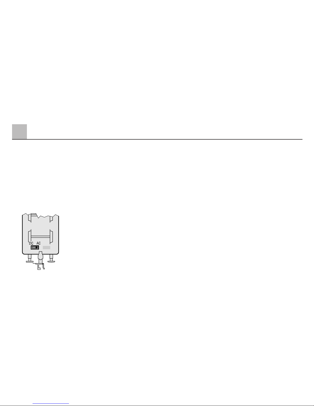
2.2 Choix du courant
d'alimentation
Le sélecteur de mode d'exploitation
courant alternatif ou courant continu
se trouve sous le tender.
Position gauche: courant continu.
Position droite: courant alternatif.
Le mode d'exploitation Digital/DELTA
est toujours automatiquement détecté.
Remarque:
● Le sélecteur 10 (désigné 0) situé
sur le clavier de la platine électronique doit dans tous les cas se trouver sur la position «OFF». Si ce
sélecteur est positionné autrement,
la locomotive se trouve en permanence en mode d'exploitation
«courant continu».
● En mode d'exploitation «courant
continu» ou «courant alternatif»,
on ne peut utiliser que des régulateurs qui fournissent un courant
continu lissé ou un courant alternatif sinusoïdal. Des régulateurs
générant du courant pulsé ne sont
pas appropriés.
● En usine, cette locomotive est
réglée sur le mode d'exploitation
«courant alternatif».
2.3 Encodage de la vitesse
maximale et de la temporisation d’accélération
et de freinage
Pour modifier la vitesse maximale ou
les temporisations d'accélération /
freinage, il faut d'abord ôter la caisse
du tender (voir page 45).
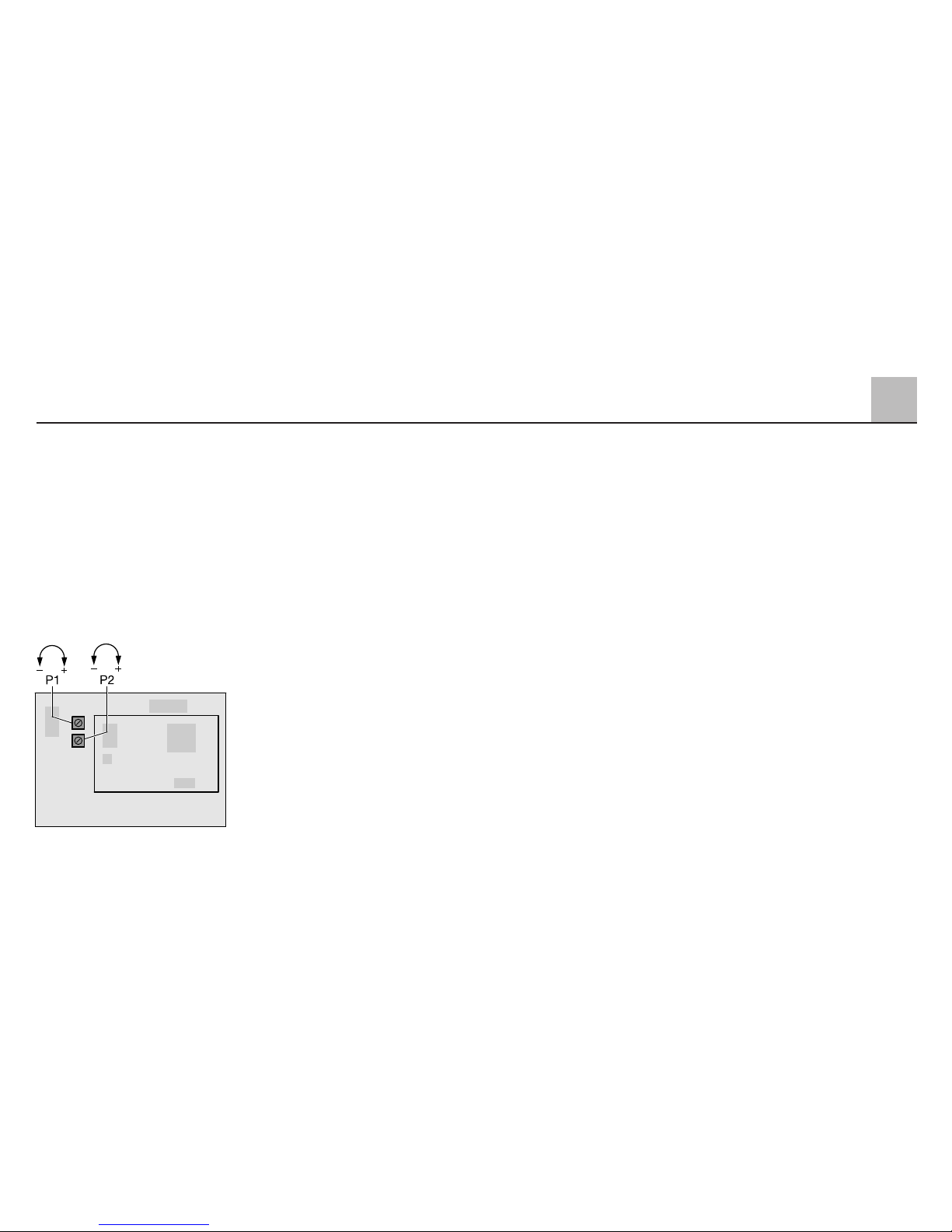
Deux potentiomètres rotatifs se trouvent sur la platine électronique, grâce
auxquels il est possible de modifier la
vitesse maximum et le démarrage et
le freinage progressifs de la locomotive.
Le freinage progressif ne fonctionne
qu’en mode Digital.
Potentiomètre rotatif 1 (P 1):
Le démarrage et le freinage progressifs sont modifiés ensemble
Butée gauche: retard minimum
Butée droite: retard maximum
Potentiomètre rotatif 2 (P 2):
Réglage de la vitesse maximum
Butée gauche: vitesse maximum
minimale
Butée droite: vitesse maximum
maximale
La vitesse de pointe maximale et une
progressivité moyenne au démarrage
et ouf freinage ont été réglées en usine.
Le régulation de vitesse dépendante
de la charge agit automatiquement.
Pour des raisons techniques, ce
réglage n’est pas aussi efficace dans
les modes d’exploitation «Courant
alternatif» et «Courant continu»,
qu’en position «Digital».
24
2
Fonctionnement
Page 25
En exploitation Digital avec la
Control Unit 6021, les temporisations
d'accélération/freinage peuvent être
réglées sur le minimum à l'aide de la
touche «f4». Ceci constitue un avantage, par exemple pour effectuer des
manœuvres en permettant un contrôle direct de la locomotive.
2.4 Fonctionnement selon
les différents systèmes
d’alimentation
2.4.1 Digital/DELTA
La Control Unit (6021) peut être
utilisée pour la commande, 4 microrupteurs sont disposés à l’arrière de
la Control Unit. Pour le fonctionnement
avec les véhicules Märklin 1, ils sont
amenés dans les positions suivantes:
Microrupteur
12 34
on on on off
Les microrupteurs ne peuvent être
modifiés qu’une fois la Control Unit
éteinte. L’affichage du sens de la
marche est par exemple activé grâce
à ces microrupteurs.
En cas d’utilisation de la Central
Unit 6020, les 4 fonctions supplé-
mentaires f 1 à f4
ne peuvent pas
être excitées. L’indication du sens de
la marche est également impossible
avec cette unité centrale.
En position Digital, cette locomotive
peut également être commandée
avec la DELTA-Station par le biais
d’un régulateur manuel DELTA-Mobil,
si l’une des quatre adresses DELTA
possibles est réglée sur le commutateur de codage d’adresse. La fonction
d’eclairage est connectée en exploitation avec la DELTA-Station.
2.4.1.1 Réglage de l’adresse de
la locomotive
Pour modifier l'adresse de la locomotive, il faut d'abord ôter la caisse
du tender (voir page 45).
L'adresse Digital de la locomotive est
réglée à l'aide du clavier d'encodage
à 10 sélecteurs situé sur la platine
électronique. En usine, c'est l'adres-
se «45» qui est encodée. Le tableau
suivant donne la correspondance
entre les adresses possibles et les
positions des sélecteurs.
25
2
Fonctionnement
Page 26
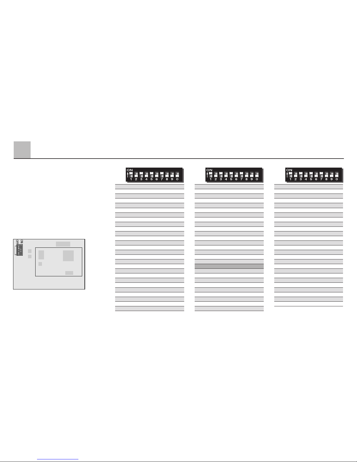
26
Si l’on règle les adresses 24, 60, 72
ou 78, la locomotive peut également
être commandée avec la DELTAStation, en liaison avec le régulateur
manuel DELTA-Mobil.
Remarque:
les sélecteurs 9 et 10 (désignés
respectivement «9» et «0») doivent
toujours être sur la position «OFF».
Digital
Digital
Digital
28 – 2 3 – 5 – – 8 – –
29 – – 3 – 5 – – 8 – –
30 1 – – 4 5 – – 8 – –
31 – 2 – 4 5 – – 8 – –
32 – – – 4 5 – – 8 – –
33 1 – – – 5 – – 8 – –
34 – 2 – – 5 – – 8 – –
35 – – – – 5 – – 8 – –
36 1 – 3 – – 6 – 8 – –
37 – 2 3 – – 6 – 8 – –
38 – – 3 – – 6 – 8 – –
39 1 – – 4 – 6 – 8 – –
40 – 2 – 4 – 6 – 8 – –
41 – – – 4 – 6 – 8 – –
42 1 – – – – 6 – 8 – –
43 – 2 – – – 6 – 8 – –
44 – – – – – 6 – 8 – –
45 1 – 3 – – – – 8 – –
46 – 2 3 – – – – 8 – –
47 – – 3 – – – – 8 – –
48 1 – – 4 – – – 8 – –
49 – 2 – 4 – – – 8 – –
50 – – – 4 – – – 8 – –
51 1 – – – – – – 8 – –
52 – 2 – – – – – 8 – –
53 – – – – – – – 8 – –
54 1 – 3 – 5 – – – – –
55 – 2 3 – 5 – – – – –
56 – – 3 – 5 – – – – –
57 1 – – 4 5 – – – – –
58 – 2 – 4 5 – – – – –
59 – – – 4 5 – – – – –
60 1 – – – 5 – – – – –
61 – 2 – – 5 – – – – –
62 – – – – 5 – – – – –
63 1 – 3 – – 6 – – – –
64 – 2 3 – – 6 – – – –
65 – – 3 – – 6 – – – –
66 1 – – 4 – 6 – – – –
67 – 2 – 4 – 6 – – – –
68 – – – 4 – 6 – – – –
69 1 – – – – 6 – – – –
70 – 2 – – – 6 – – – –
71 – – – – – 6 – – – –
72 1 – 3 – – – – – – –
73 – 2 3 – – – – – – –
74 – – 3 – – – – – – –
75 1 – – 4 – – – – – –
76 – 2 – 4 – – – – – –
77 – – – 4 – – – – – –
78 1 – – – – – – – – –
79 – 2 – – – – – – – –
80 1 – 3 – 5 – 7 – – –
01 – 2 3 – 5 – 7 – – –
02 – – 3 – 5 – 7 – – –
03 1 – – 4 5 – 7 – – –
04 – 2 – 4 5 – 7 – – –
05 – – – 4 5 – 7 – – –
06 1 – – – 5 – 7 – – –
07 – 2 – – 5 – 7 – – –
08 – – – – 5 – 7 – – –
09 1 – 3 – – 6 7 – – –
10 – 2 3 – – 6 7 – – –
11 – – 3 – – 6 7 – – –
12 1 – – 4 – 6 7 – – –
13 – 2 – 4 – 6 7 – – –
14 – – – 4 – 6 7 – – –
15 1 – – – – 6 7 – – –
16 – 2 – – – 6 7 – – –
17 – – – – – 6 7 – – –
18 1 – 3 – – – 7 – – –
19 – 2 3 – – – 7 – – –
20 – – 3 – – – 7 – – –
21 1 – – 4 – – 7 – – –
22 – 2 – 4 – – 7 – – –
23 – – – 4 – – 7 – – –
24 1 – – – – – 7 – – –
25 – 2 – – – – 7 – – –
26 – – – – – – 7 – – –
27 1 – 3 – 5 – – 8 – –
2
Fonctionnement
Page 27

2.4.1.2 Conduite de la locomotive
en mode Digital
Pour conduire la locomotive avec
Märklin Digital, l’adresse de la
locomotive est enregistrée sur la
Control Unit (6021) ou sur un régulateur de vitesse Control 80 f (6036)
connecté. En tournant le régulateur
vers la droite, on augmente la vitesse
de la locomotive et en le tournant
vers la gauche, on la réduit en conséquence. Si le régulateur est tourné
au-delà de la position «0» vers la
gauche, le sens de la marche est
inversé. Gråce à la touche «fonction»,
l’éclairage dans la locomotive peut
être actionné en fonction du sens de
la marche. La touche «off» permet
de l’éteindre.
Via les touches «f1» à «f4», on peut
commuter les fonctions suivantes:
f1 = Générateur fumigène et éclairage
du poste de conduite on / off
f2 = Bruiteur de cloche on / off
f3 = Bruiteur de sifflet on / off
f4 = Minimalisation de la tempori-
sation d'accélération-freinage
(voir 2.3)
Remarques sur les accessoires
fonctionnels:
Le générateur fumigène ne peut être
activé longtemps sans liquide fumigène. L'opérateur peut se rendre
compte si cette fonction est activée
en constatant si l'éclairage du poste
de conduite est activé également.
La locomotive réelle ne possède pas
de cloche. Mais comme le bruiteur
équipant le modèle réduit peut reproduire le son d'une cloche, cette fonction existante a également été rendue
commutable sur ce modèle. Le
modéliste soucieux de réalisme se
gardera donc d'activer la fonction f2.
Les autres opérateurs moins soucieux
de réalisme peuvent néanmoins se
servir de cette fonction à volonté.
Le bruiteur intégré peut être activé
et désactivé manuellement (voir 2.5).
Il est prévu uniquement pour une
exploitation en mode Digital ou DELTA.
2.4.2 Conduite de la locomotive
en mode DELTA
L'adresse qui a été réglée pour la
locomotive est choisie sur le régulateur manuel DELTA-Mobil pour permettre à la locomotive de fonctionner
en Märklin DELTA. Si l’on actionne le
régulateur de conduite de la position
centrale vers la droite, la locomotive
se déplace en marche avant. Si l'on
actionne le régulateur de conduite
de la position centrale vers la gauche,
la locomotive se déplace en marche
arrière. L'éclairage en fonction du
sens de la marche est constamment
enclenché. La puissance de sortie
maximum de la DELTA-Station est
suffisante pour une exploitation
simultanée de 2 à 3 locomotives à un
seul moteur.
En exploitation avec la Station DELTA,
parmi les fonctions f1 à f4, la fonction f1
est toujours activée. Les fonctions
restantes sont toujours désactivées.
27
2
Fonctionnement
Page 28

2.4.3 Conduite en tension alternative
Dans le mode d'exploitation «courant
alternatif», la locomotive peut être
pilotée par exemple avec le transformateur de 32 VA (n° 6645, 6646,
6647 ou 76648). En tournant le régulateur de vitesse vers la droite, la
vitesse de la locomotive est augmentée, en le tournant vers la gauche elle est réduite en conséquence.
Si le régulateur est tourné au-delà de
la position «0» vers la gauche, le sens
de la marche est inversé. La commande d'inversion du sens de la
marche ne devrait jamais être transmise à une locomotive en circulation,
mais toujours à une locomotive se
trouvant à l‘ arrêt.
L'éclairage en fonction du sens de la
marche est enclenché en exploitation
sous tension alternative. L'intensité
de l'éclairage dépend de la vitesse.
En cours d'exploitation, parmi les
fonctions f1 à f4, la fonction f1 est
toujours activée. Les fonctions
restantes sont toujours dèsactivées.
2.4.4 Conduite en tension continue
Les régulateurs de vitesse à tension
continue ne sont pas proposés par
Märklin pour les modèles de Voie 1.
Les régulateurs de vitesse à tension
continue ayant une tension maximale
de ±18 volt sont adaptés. Le changement du sens de la marche est réalisé
grâce à un changement de polarité.
Vous trouverez les instructions de
commande relatives aux différents
régulateurs de vitesse dans la notice
du fabricant.
Indication:
Les régulateurs de vitesse H0 à ten-
sion continue fournissent une tension
maximum de ±12 volt. La locomotive
n'atteint cependant sa pleine capacité qu'avec ±16 volt. Les régulateurs
de vitesse H0 à tension continue ne
peuvent donc être utilisés qu'avec
certaines restrictions.
L'éclairage en fonction du sens de la
marche est enclenché en exploitation
sous tension continue. L'intensité de
léclairage dépend de la vitesse.
En cours d'exploitation, parmi les
fonctions f1 à f4, la fonction f1 est
toujours activée. Les fonctions
restantes sont toujours dèsactivées.
28
2
Fonctionnement
Page 29
2.5 Le bruiteur intégré
Le bruiteur électronique intégré
reproduit les sons émis par une locomotive à vapeur conformément à
l'état de marche. Ce bruiteur peut
être activé et désactivé via un sélecteur logé sur le tender.
Remarque:
Comme ce bruiteur nécessite un
minimum de courant, il est prévu
pour fonctionner uniquement en
exploitation Märklin Digital ou DELTA.
En exploitation en courant alternatif
ou continu, le bruiteur ne se fait
entendre qu'à partir d'une certaine
vitesse. En cas de perturbation, il se
peut que le bruiteur se révèle défaillant. Nous recommandons par
conséquent de ne faire fonctionner le
bruiteur qu'en mode Märklin Digital
ou DELTA.
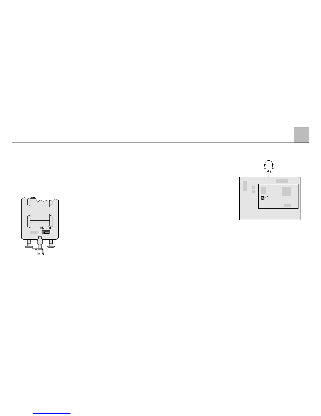
2.5.1 Réglage de l’intensité du son
Sur la platine de bruitage se trouve
un potentiomètre (P3) permettant de
régler l’intensité sonore sur l’entièreté
de sa plage. Enlevez, pour ce faire,
la caisse du tender (voir page 45).
Remarque importante:
A côté du potentiomètre de réglage
de l’intensité du son, on trouve sur la
platine un clavier à 8 sélecteurs de
codage. Grâce à ce clavier, l’électronique de bruitage est réglée en usine
d’une façon optimale sur votre locomotive. Ne modifiez donc jamais ce
réglage!
29
2
Fonctionnement
Page 30

2.1 Werking
Deze loc met ingebouwde digitaalelektronica biedt u:
● Keuze uit de volgende bedrijfs-
systemen:
I. Conventioneel wisselspannings-
bedrijf met bijv. een transformator 32 VA
II. Conventioneel gelijkspannings-
bedrijf (max. 18 V=)
III. Meer-treinenbedrijf met het
Märklin DELTA systeem (alleen
met het DELTA Station 6607)
IV. Meer-treinenbedrijf met het
Märklin digitaal systeem
(alleen Control Unit 6021)
Het gebruik met andere systemen
zoals bijv. impulsbreedte sturing of
de oudere Märklin centrale eenheid
Central-control 1 (art. nr. 6030) is
niet mogelijk.
● Automatische herkenning tussen
conventioneel en digitaal-/DELTAbedrijf. De keuze tussen wisselspanning en gelijkspanning bij
conventioneel bedrijf wordt handmatig op de print of met de bedrijfskeuzeschakelaar aan de onderkant
van de tender ingesteld.
● 80 digitale- (4 DELTA-) adressen
instelbaar met de codeerschakelaar. Vanaf de fabriek is het adres 45
ingesteld.
● Instelbare maximumsnelheid.
● Instelbare optrek- afremvertraging.
Afremvertraging werkt niet bij conventioneel bedrijf.
● Rijrichtingsafhankelijke frontver-
lichting, bij digitaal bedrijf in- en uitschakelbaar. Bij conventioneel
bedrijf is de intensiteit van de verlichting afhankelijk van de snelheid.
Bij het bedrijf met DELTA Station is
de frontverlichting continu ingeschakeld.
● Alleen bij het gebruik met digitaal /
DELTA: handmatig inschakelbare
stoomlocomotief geluidsmodule.
● Ingebouwde rookgenerator,
in het digitale bedrijf met Control
Unit 6021, ook uitschakelbaar.
● Met de rookgenerator wordt gelijk-
tijdig de verlichting van het machinistenhuis ingeschakeld.
● Alleen bij het bedrijf met de
Control Unit 6021: schakelbaar
geluid van een locomotieffluit.
● Alleen bij het gebruik van de
Control Unit 6021: minimalisering
van de ingestelde optrek- afremvertraging.
● Voorzijde gemonteerde schroef-
koppeling, achterzijde gemonteerde
klauwkoppeling. Voor beide zijden
zijn omruilkoppelingen meegeleverd.
● Kleinst berijdbare radius: 1020 mm.
Deze radius is alleen te berijden,
als de aangekoppelde wagens
aan de Märklin klauwenkoppeling
gekoppeld zijn.
● Het model is ontwikkeld voor het
gebruik op het Märklin Profi 1railsysteem. Het gebruik op een
ander railsysteem geschied op
eigen risico.
30
2
Exploitatie
Page 31
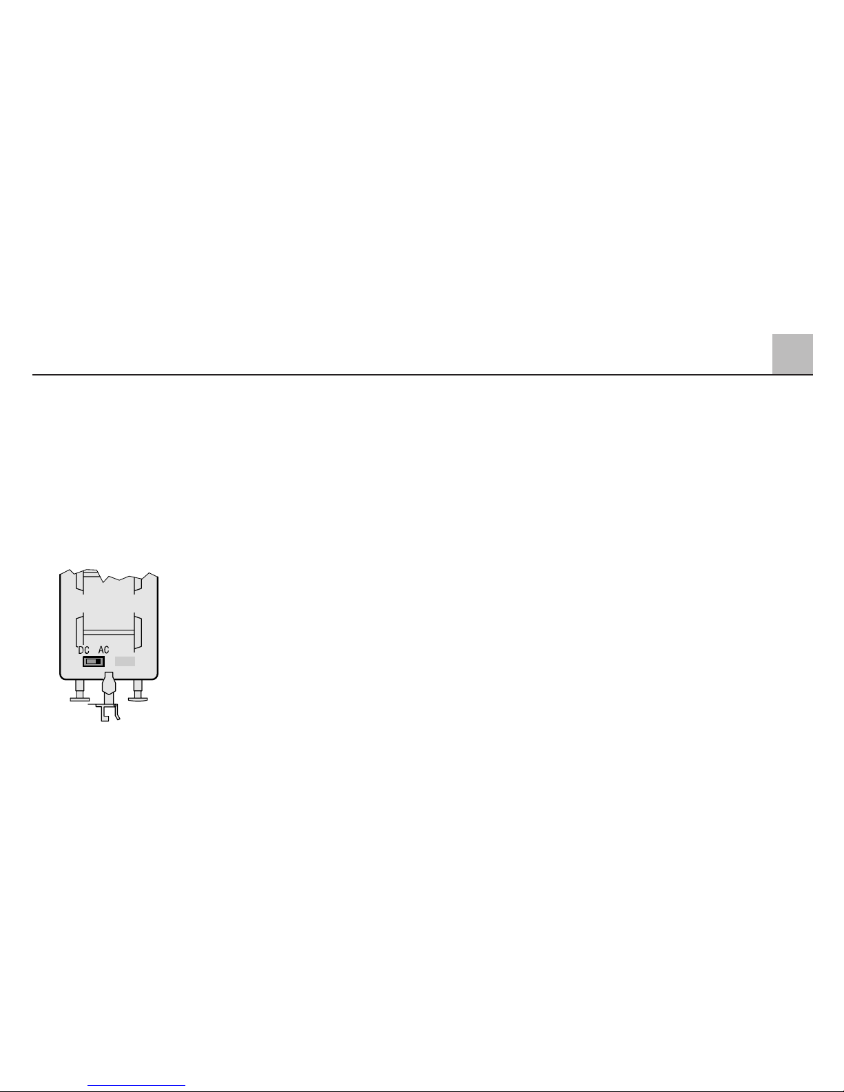
2.2 Kiezen van de voedingsspanning
De schakelaar voor het bedrijfssysteem, wissel- of gelijkstroom
bevindt zich onder de tender.
Stand naar links: gelijkstroom
Stand naar rechts: wisselstroom
Het bedrijfssysteem digitaal/DELTA
wordt altijd automatisch herkend.
Opmerking:
● De schakelaar 10 (gemerkt met 0)
van de adresschakelaar op de
digitale elektronica-print dient in
elk geval op „off“ te staan. Anders
staat de naar buiten gevoerde
bedrijfsschakelaar buiten werking
en bevindt zich de loc voortdurend
in het bedrijfssysteem „gelijkstroom”.
● Voor de bedrijfssystemen „gelijk-
stroom“ en „wisselstroom“ kunnen
uitsluitend rijregelaars gebruikt
worden die een afgevlakte gelijkstroom of een zuiver sinusvormige,
wisselspanning afgeven. Rijregelaars met impuls-breedte sturing
zijn niet toe te passen.
● Vanaf de fabriek is de loc ingesteld
op het bedrijfssysteem „wisselstroom”.
2.3 Instellen van de maximale
snelheid en de optrek- en
afremvertraging
Voor het wijzigen van de maximumsnelheid of de optrek- en afremvertraging dient eerst de kap van de tender
verwijderd te worden (zie pag. 45).
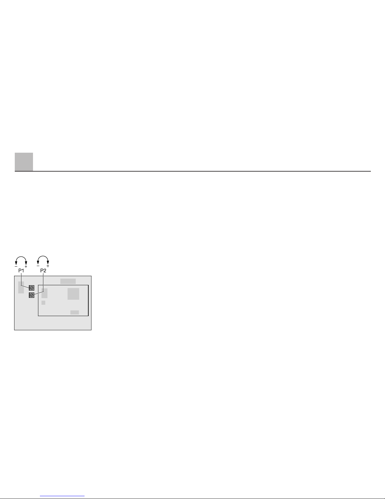
Op de print bevinden zich twee
draaipotentiemeters waarmee de
optreken afremvertraging of de maximum snelheid van de loc veranderd
kunnen worden. De afremvertaging
werkt alleen in het digital-bedrijf.
Draaipotmeter 1 (P 1):
Optrek- en afremvertraging worden
beide gelijktijdig veranderd.
Linksom: minimale vertraging
Rechtsom: maximale vertraging
Draaipotmeter 2 (P 2):
Instelling van de maximum snelheid.
Linksom: lage maximale snelheid
Rechtsom: hoge maximale snelheid
Op de fabriek is de maximale top-
snelheid en een gemiddelde optreken afremvertraging ingesteld.
De lastafhankelijke na regeling werkt
automatisch. Door technische beperkingen werkt deze regeling in de
bedrijfsstand „wisselstroom“ of „gelijkstroom“ niet zo opvallend als in de
stand „Digital“.
31
2
Exploitatie
Page 32
In het digitale bedrijf met de
Control Unit 6021 kan door het
inschakelen van de extra functie „f4“
de ingestelde optrek- en afremvertraging geminimaliseerd worden. Dit
is bijvoorbeeld bij het rangeren een
groot voordeel, als men een directe
besturing van de loc wenst.
2.4 Het bedrijf
2.4.1 Digital/DELTA
Voor de regeling kan de Control Unit
(6021) gebruikt worden. Op de
achterzijde van de Control Unit
bevinden zich vier codeerschakelaars
die voor het bedrijf met Märklin 1voertuigen in de volgende positie
gezet worden:
Schakelaar
12 34
on on on off
De schakelaars mogen alleen bij uitgeschakelde Control Unit veranderd
worden. Via deze schakelaars wordt
bijvoorbeeld de indicatie van de rijrichting in de Control Unit geactiveerd.
Bij gebruik van Central Unit 6020
kunnen de vier extra functies f 1 tot
en met f 4
niet aangesproken worden. Evenzo vervalt bij deze centrale
eenheid de indicatie van de rijrichting.
Als een van de vier mogelijke DELTA
adressen op de codeerschakelaar
voor de adressen ingesteld is, kan
deze lok in de stand Digital ook met
het DELTA-Station via een handregelaar DELTA-Mobil geregeld worden.
Bij gebruik met het DELTA-Station is
de lichtfunctie ingeschakeld.
2.4.1.1 Instellen van het loc-adres
Voor het instellen van het loc-adres
dient eerst de kap van de tender verwijderd te worden (zie pag. 45).
Het digitale adres van de loc wordt
met de tienpolige codeerschakelaar
op de elektronica-print ingesteld.
Vanaf de fabriek is het adres „45“
ingesteld. De volgende tabel geeft
een overzicht van alle mogelijke loc
adressen met de bijbehorende stand
van de schakelaars.
32
2
Exploitatie
Page 33
2
33
Exploitatie
Als de adressen 24, 60, 72 of 78
ingesteld worden, dan kan de loc
ook met het DELTA-Station in combinatie met handregelaar DELTA
geregeld worden.
Opmerking:
de schakelaar 9+10 (gemerkt met „9“
en „0“) moeten altijd in de stand „off“
staan
.
Digital
Digital
Digital
28 – 2 3 – 5 – – 8 – –
29 – – 3 – 5 – – 8 – –
30 1 – – 4 5 – – 8 – –
31 – 2 – 4 5 – – 8 – –
32 – – – 4 5 – – 8 – –
33 1 – – – 5 – – 8 – –
34 – 2 – – 5 – – 8 – –
35 – – – – 5 – – 8 – –
36 1 – 3 – – 6 – 8 – –
37 – 2 3 – – 6 – 8 – –
38 – – 3 – – 6 – 8 – –
39 1 – – 4 – 6 – 8 – –
40 – 2 – 4 – 6 – 8 – –
41 – – – 4 – 6 – 8 – –
42 1 – – – – 6 – 8 – –
43 – 2 – – – 6 – 8 – –
44 – – – – – 6 – 8 – –
45 1 – 3 – – – – 8 – –
46 – 2 3 – – – – 8 – –
47 – – 3 – – – – 8 – –
48 1 – – 4 – – – 8 – –
49 – 2 – 4 – – – 8 – –
50 – – – 4 – – – 8 – –
51 1 – – – – – – 8 – –
52 – 2 – – – – – 8 – –
53 – – – – – – – 8 – –
54 1 – 3 – 5 – – – – –
55 – 2 3 – 5 – – – – –
56 – – 3 – 5 – – – – –
57 1 – – 4 5 – – – – –
58 – 2 – 4 5 – – – – –
59 – – – 4 5 – – – – –
60 1 – – – 5 – – – – –
61 – 2 – – 5 – – – – –
62 – – – – 5 – – – – –
63 1 – 3 – – 6 – – – –
64 – 2 3 – – 6 – – – –
65 – – 3 – – 6 – – – –
66 1 – – 4 – 6 – – – –
67 – 2 – 4 – 6 – – – –
68 – – – 4 – 6 – – – –
69 1 – – – – 6 – – – –
70 – 2 – – – 6 – – – –
71 – – – – – 6 – – – –
72 1 – 3 – – – – – – –
73 – 2 3 – – – – – – –
74 – – 3 – – – – – – –
75 1 – – 4 – – – – – –
76 – 2 – 4 – – – – – –
77 – – – 4 – – – – – –
78 1 – – – – – – – – –
79 – 2 – – – – – – – –
80 1 – 3 – 5 – 7 – – –
01 – 2 3 – 5 – 7 – – –
02 – – 3 – 5 – 7 – – –
03 1 – – 4 5 – 7 – – –
04 – 2 – 4 5 – 7 – – –
05 – – – 4 5 – 7 – – –
06 1 – – – 5 – 7 – – –
07 – 2 – – 5 – 7 – – –
08 – – – – 5 – 7 – – –
09 1 – 3 – – 6 7 – – –
10 – 2 3 – – 6 7 – – –
11 – – 3 – – 6 7 – – –
12 1 – – 4 – 6 7 – – –
13 – 2 – 4 – 6 7 – – –
14 – – – 4 – 6 7 – – –
15 1 – – – – 6 7 – – –
16 – 2 – – – 6 7 – – –
17 – – – – – 6 7 – – –
18 1 – 3 – – – 7 – – –
19 – 2 3 – – – 7 – – –
20 – – 3 – – – 7 – – –
21 1 – – 4 – – 7 – – –
22 – 2 – 4 – – 7 – – –
23 – – – 4 – – 7 – – –
24 1 – – – – – 7 – – –
25 – 2 – – – – 7 – – –
26 – – – – – – 7 – – –
27 1 – 3 – 5 – – 8 – –
Page 34

2.4.1.2 Rijden van de loc met Digital
Om de loc met Märklin Digital te
kunnen rijden, wordt het locadres op
de Control Unit (6021) of een aangesloten rijregelaar Control 80 f
(6036) ingevoerd. Door de rijregelaar
naar rechts te draaien versnelt de loc
en door naar links te draaien vermindert de snelheid in gelijke mate. Als
de rijregelaar door de stand „0“ heen
verder naar links gedraaid wordt, dan
wordt de rijrichting omgeschakeld.
Met de toets „function“ kan de verlichting in de lok afhankelijk van de
richting ingeschakeld worden en met
de toets „off“ weer uitgeschakeld
worden.
Via de toetsen „f1“ t/m „f4“ kunnen
de volgende functies geschakeld
worden:
f1 = Rookgenerator en machinisten-
huisverlichting aan / uit
f2 = Geluid van luidklok aan / uit
f3 = Geluid van locfluit aan / uit
f4 = Optrek- en afremvertraging
minimaliseren (zie 2.3)
Opmerking voor het gebruik van de
functies:
De rookgenerator mag niet gedurende
langere tijd zonder rookvloeistof ingeschakeld zijn. Om er voor te zorgen
dat men kan zien of deze functie
ingeschakeld is, wordt daarom bij dit
model gelijktijdig de binnenverlichting
van het machinistenhuis ingeschakeld.
Het voorbeeld van deze locomotief
beschikt weliswaar geen luidklok.
Echter omdat de ingebouwde
geluidsmodule wel over deze functie
beschikt, is deze functie toch schakelbaar uitgevoerd.
Als men getrouw naar het voorbeeld
wil rijden, zal men de functie f2 niet
gebruiken. Diegene die minder
nadruk legt op het voorbeeldgetrouw
rijden kan zich op deze functie verheugen.
De ingebouwde geluidselektronica
kan handmatig in- en uitgeschakeld
worden (zie 2.5). De geluidselektronica
is alleen bedoelt voor het gebruik in
het digitaal- of DELTA-bedrijf.
2.4.2 Rijden van de loc met DELTA
Om met de loc binnen Märklin DELTA
te kunnen rijden, wordt op de handregelaar DELTA Mobil het ingestelde
locadres gekozen. Door draaien aan
de rijregelaar vanuit de middenstand
naar rechts rijdt de loc vooruit. Door
draaien aan de rijregelaar venuit de
middenstand naar links rijdt de loc
achteruit. De rijrichtingafhankelijke
verlichting is constant ingeschakeld.
Het maximale uitgangsvermogen van
het DELTA Station is voldoende om
tegelijk met 2 à 3 eenmotorige locomotieven te laten rijden.
Van de functie „f1” tot „f4” is, bij het
DELTA Station gebruik, de functie
„f1” altijd ingeschakeld. De andere
functies zijn altijd uitgeschakeld.
34
2
Exploitatie
Page 35

2.4.3 Rijden van wisselspanning
Bij het wisselstroombedrijf kan de loc
bijv. met de transformator 32 VA
(nr. 6645, 6646, 6648 of 76648)
bestuurd worden. Door de rijregelaar
naar rechts te draaien versnelt de loc
en naar links vermindert de snelheid.
Als de rijregelaar door de stand „0”
heen verder naar links gedraaid
wordt, dan wordt de rijrichting omgeschakeld. Het omschakelbevel voor
de rijrichting mag nooit aan een rijdende loc, maar altijd alleen aan een
stilstaande loc gegeven worden.
Bij gebruik met wisselspanning is de
rijrichtingafhankelijke verlichting ingeschakeld. De helderheid van de verlichting is afhankelijk van de snelheid.
Van de functie „f1” tot „f4” is, bij het
conventionele gebruik, de functie „f1”
altijd ingeschakeld. De andere functies
zijn altijd uitgeschakeld.
2.4.4 Rijden van gelijkspanning
Rijregelaars voor gelijkspanning worden door Märklin niet voor spoor 1modellen aangeboden. Geschikte
rijregelaars voor gelijkspanning leveren
een maximale spanning van ±18 volt.
De wisseling van de rijrichting wordt
door ompolen bewerkstelligd. De
bediening van uw arijregelaar leest
u in de handleiding van de fabrikant.
Opmerking:
H0-gelijkspanningsapparaten geven
een maximale spanning van ±12 volt
af. De loc bereikt zijn
volle vermogen echter pas bij ±16 volt.
H0-gelijkspanningsapparaten zijn
daardoor slechts beperkt abruikbaar.
Bij gebruik met gelijkspanning is de
rijrichtingafhankelijke verlichting ingeschakeld. De helderheid van de verlichting is afhankelijk van de snelheid.
Van de functie „f1” tot „f4” is, bij het
gelijkstroom gebruik, de functie „f1”
altijd ingeschakeld. De andere functies
zijn altijd uitgeschakeld.
2
35
Exploitatie
Page 36
2.5 De ingebouwde
geluidselektronica
De ingebouwde geluidselektronica
geeft bij elke rijstand van de loc het
passende geluid van een stoomlocomotief weer. De geluidselektronica
kan door een schakelaar op de tender
aan- en uitgeschakeld worden.
Opmerking:
aangezien deze geluidselektronica
een minimale voedingsspanning
nodig heeft, is deze bedoelt voor het
voor het gebruik met Märklin digitaal
of DELTA . Bij het gebruik in het wissel- of gelijkspanningsbedrijf zal het
geluid pas bij een bepaalde snelheid
te horen zijn. Door stoorsignalen kan
het daarbij ook voorkomen dat er
een verkeerde geluidsweergave
ontstaat. Daarom is het dan ook aan
te bevelen de geluidselektronica uitsluitend te gebruiken bij het Märklin
digitaal of DELTA bedrijf.
2.5.1 Instellen van het volume
Op de geluidsprint (P3) kan met
behulp van een potentiometer het
totale geluid geregeld worden.
Verwijder hiervoor de tenderkap
(zie pag. 45).
Belangrijke opmerking: naast de
potentiometer voor de volumeregeling bevindt zich een 8-voudige
codeerschakelaar op de geluidsprint.
Met deze codeerschakelaar wordt de
geluidselektronica, in de fabriek, optimaal aangepast aan uw locomotief.
Verander daarom de instellingen op
deze codeerschakelaar nooit!
36
2
Exploitatie
Page 37

3.1 Anschluss der Gleisanlage
Um Spannungsverluste auf der Anlage
zu vermeiden ist immer auf gutes
Zusammenpassen der Schienenverbindungslaschen zu achten. Alle 2 bis
3 m ist eine neue Stromeinspeisung
über die Anschlussklemmen 5654
empfehlenswert.
Die Verwendung der Gleisklammern
56031 bei temporär aufgebauten
Anlagen verringert ebenfalls die
Spannungsverluste.
3.2 Befahren von Steigungen
Im Gegensatz zum Vorbild können
mit einer Modellbahn auch größere
Steigungen befahren werden. Im
Normalfall sollte eine Steigung bei
maximal 3 Prozent liegen. Im Extremfall sind bei entsprechend eingeschränkter Zugleistung maximal
5 Prozent möglich. Der Anfang und
das Ende der Steigung sind auf jeden
Fall auszurunden. Der Unterschied in
der Steigung zwischen zwei mindestens 300 mm langen Gleisstücken
darf maximal 1 bis 1,5 Prozent betragen.
3.3 Befahren von gebogenen
Gleisen
Diese Lok fährt nur auf Gleisbögen
mit einem Radius größer / gleich
1020 mm. Die vorne montierte
Schraubenkupplung ist nur für das
Ankuppeln von Wagen in einer Vitrine
geeignet.
3
37
Betrieb auf einer Anlage
Page 38

3.1 Connections between
the track layout and the
transformer
Rail joiners must fit well on the rails
of the track to which they are joined
to avoid voltage drop on the layout.
We recommend that you install
feeder wires every 2 to 3 meters
(10 to 16 feet) using the 5654 feeder
clips.
Using the 56031 track clips on
temporary layouts will minimize the
voltage loss.
3.2 Operating the locomotive
on grades
In contrast to the prototype a locomotive on a model railroad can operate up steeper grades. As a general
rule a grade should be no steeper
than 3%. In extreme situations a
maximum grade of 5% is permissible,
keeping in mind that the locomotive's
tractive effort will be less. The beginning and the end of the grade must
always work gradually up to the
maximum grade for the route. The
maximum allowable difference in
grade between two track sections,
each with a minimum length of
300 mm (11-
3
/4”) is 1 to 1.5 percent.
3.3 Operation over curved
track
This locomotive requires curves with
a radius of 1,020 mm / 40-
3
/16” or
greater for operation. The reproduction
prototype coupler mounted on the
front of the locomotive is only suitable
for coupling to cars in a display case.
38
3
Operation on a layout
Page 39

3.1 Connexion des voies
ferrées
Pour éviter des pertes de potentiel
sur l'installation, il faut veiller à ce que
les éclisses de liaison des rails soient
toujours parfaitement adaptées. Une
nouvelle alimentation électrique est
conseillée tous les 2 à 3 m au moyen
des griffes d'alimentation 5654.
L'utilisation des étriers de maintien
56031 sur des réseaux temporaires
permet de réduire également les
pertes de courant.
3.2 Franchissement des côtes
Contrairement à l'original, la maquette
est également en mesure de franchir
des côtes assez importantes. En
temps normal, une côte devrait être
de l'ordre de 3% maximum. A l'extrême limite, 5% sont envisageables
avec une puissance du train réduite
en conséquence. Le début et la fin
de la côte doivent en tous cas être
arrondis. La différence de pente
entre deux éléments de voie d'au
moins 300 mm de longueur doit être
de 1 à 1,5% maximum.
3.3 Utilisation sur des voies
en courbe
Cette locomotive ne peut emprunter
que des courbes d'un rayon minimal
de 1020 mm. L'attelage à vis monté
sur le devant de la locomotive ne
peut servir que pour accoupler des
wagons en vitrine.
3
39
Exploitation sur reseau
Page 40

3.1 Aansluiting van de sporen
Om spanningsverlies op de modelbaan
te voorkomen moeten de raillassen
altijd goed op elkaar aansluiten. Om
de 2 à 3 meter moet de voeding
opnieuw op de rails gezet worden.
Daarbij zijn de aansluitklemmen 5654
aan te raden.
Het gebruik van de railklemmen
56031 bij tijdelijk opgebouwde
modelbanen vermindert eveneens
het spanningsverlies.
3.2 Berijden van hellingen
In tegenstelling tot het grote voorbeeld kunnen met een modelbaan
ook grotere hellingen bereden worden.
Normaal moet een helling maximaal
3 procent zijn. In extreme gevallen is
maximaal 5 procent mogelijk, maar
dan moet rekening gehouden worden
met een evenredig verlies aan vermogen. Het begin en het einde van de
helling moeten altijd gerond worden.
Het verschil in de helling tussen twee
tenminste 300 mm lange railstukken
mag maximaal 1 à 1,5 procent
bedragen.
3.3 Rijden in bogen
Deze loc rijdt alleen op gebogen
rails met een radius groter of gelijk
aan 1020 mm. De aan de voorzijde
gemonteerde schroefkoppeling is
alleen voor het aankoppelen van
wagens in de vitrine geschikt.
3
40
Bedrijf op een modelbaan
Page 41
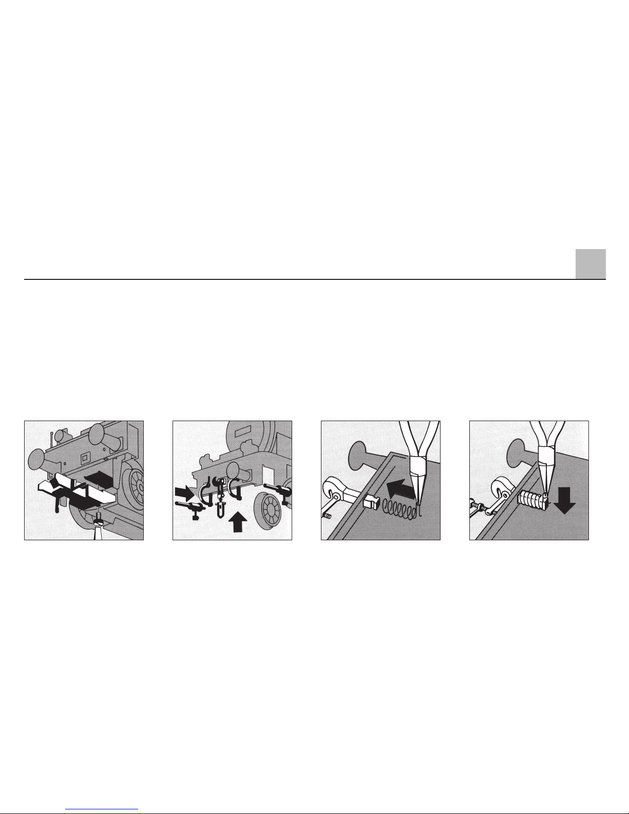
4.1 Kupplung austauschen
Beim Aufstellen der Lokomotive als
Vitrinenmodell können die automatischen Kupplungen entfernt werden.
Mit den beiliegenden Bremsschläu-
chen, Kolbenstangenschutzrohren
und Schraubenkupplungen kommt
diese Lokomotive als Vitrinenmodell
erst richtig zur Geltung.
4.1 Changing couplings
The automatic couplers can be
removed if the locomotive is to be
used as a static display. The brake
connections, piston rod protectors
and scale model screw coupler con
be installed to complete the realistic
apperance of the locomotive.
4.1 Remplacement des
chrochets d’attelages
Si vous voulez exposer votre locomotive dans une vitrine, vous pouvez
démonter les crochets automatiques.
A leur lieu et place, cous pouvez
monter les imitations de conduits de
freins, les tubes de protection des
bielles motrices ainsi que les attelages à choquelles. Ce n’est qu’ainsi
que votre loco paraîtra dans toute sa
splendeur.
4.1 Koppelingen verwisselen
Bij het opstellen van de locomotief
als vitrinemodel kunnen de automatische koppelingen worden verwijderd.
Met de bijgevoegde remslangen,
zuigerstanghulzen en schroefkoppelingen komt deze locomotief als
vitrinemodel pas goed tot zijn recht.
41
4
Wartung Maintenance Entretien Onderhoud
Page 42
4.2 Figuren einkleben
Beim Einkleben darauf achten, dass
sich die Führerhaustüren noch
schließen lassen.
4.2 Sticking figures on
When sticking figures on, ensure that
driver’s cab doors can still be closed.
4.2 Mise en place des figurines
Vérifiez lors du collage des figurines
que les mouvements des portes de
l’abri ne sont pas entravèes.
4.2 Figuren vastplakken
Bij het vastplakken er op letten, dat
de cabine-deuren nog dicht kunnen.
4.3 Tender ankuppeln
Couple up the tender
Accrocher le tender
Tender aankoppelen
4
42
Wartung Maintenance Entretien Onderhoud
Page 43

43
4
Wartung Maintenance Entretien Onderhoud
471 900
4.4 Haftreifen wechseln
Changing non-skid tires
Remplacement des bandages adhérents
Nieuwe antislipbanden omleggen
4.5 Schleifer wechseln
Changing pick-up shoes
Remplacement des frotteurs
Nieuwe sleepcontacten aanbrengen
Page 44
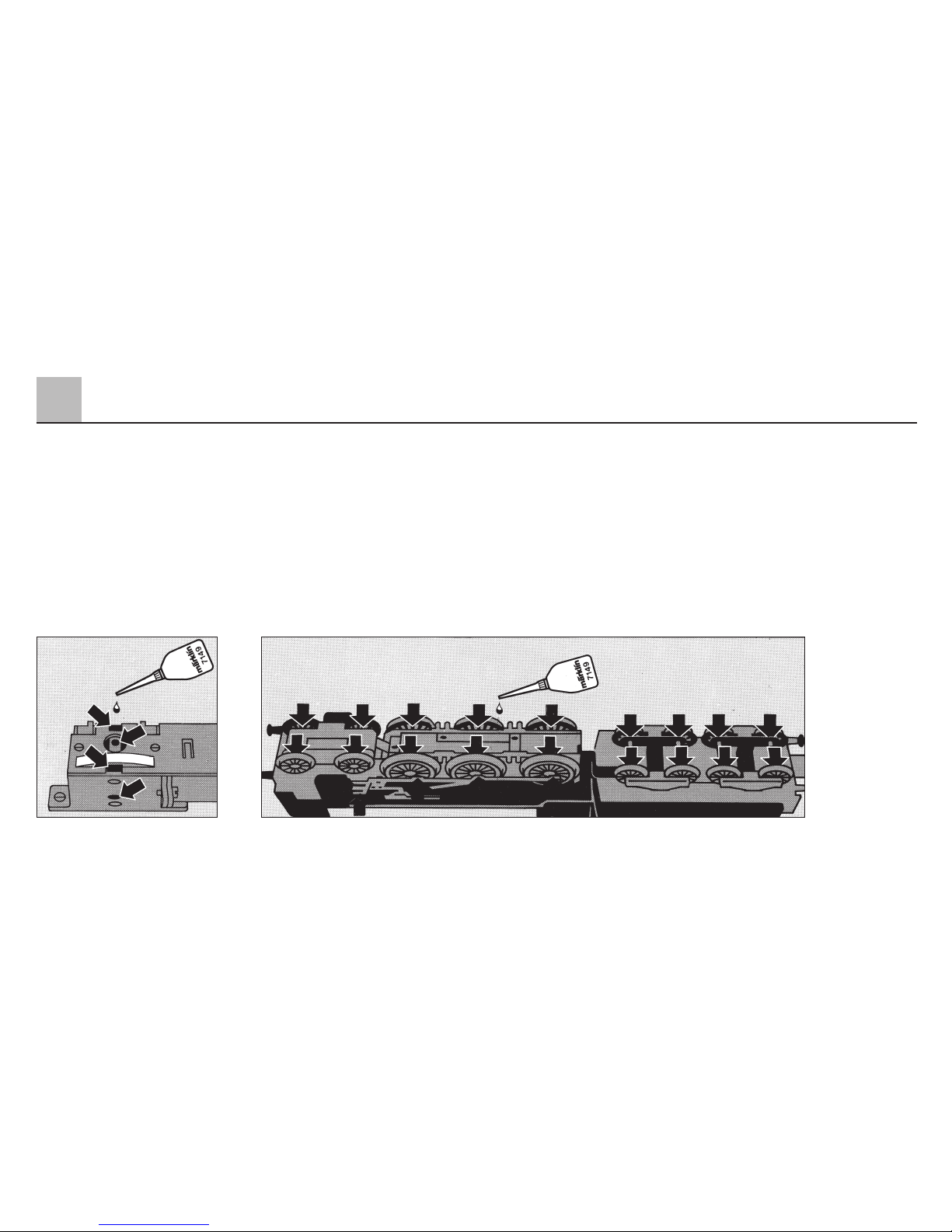
44
4
Wartung Maintenance Entretien Onderhoud
4.6 Schmierung alle 40 Betriebsstunden
Lubricate after every 40 hours of operation
Graisser toutes les 40 heures de fonctionnement
Smering omde 40 bedrijfsuren
Page 45
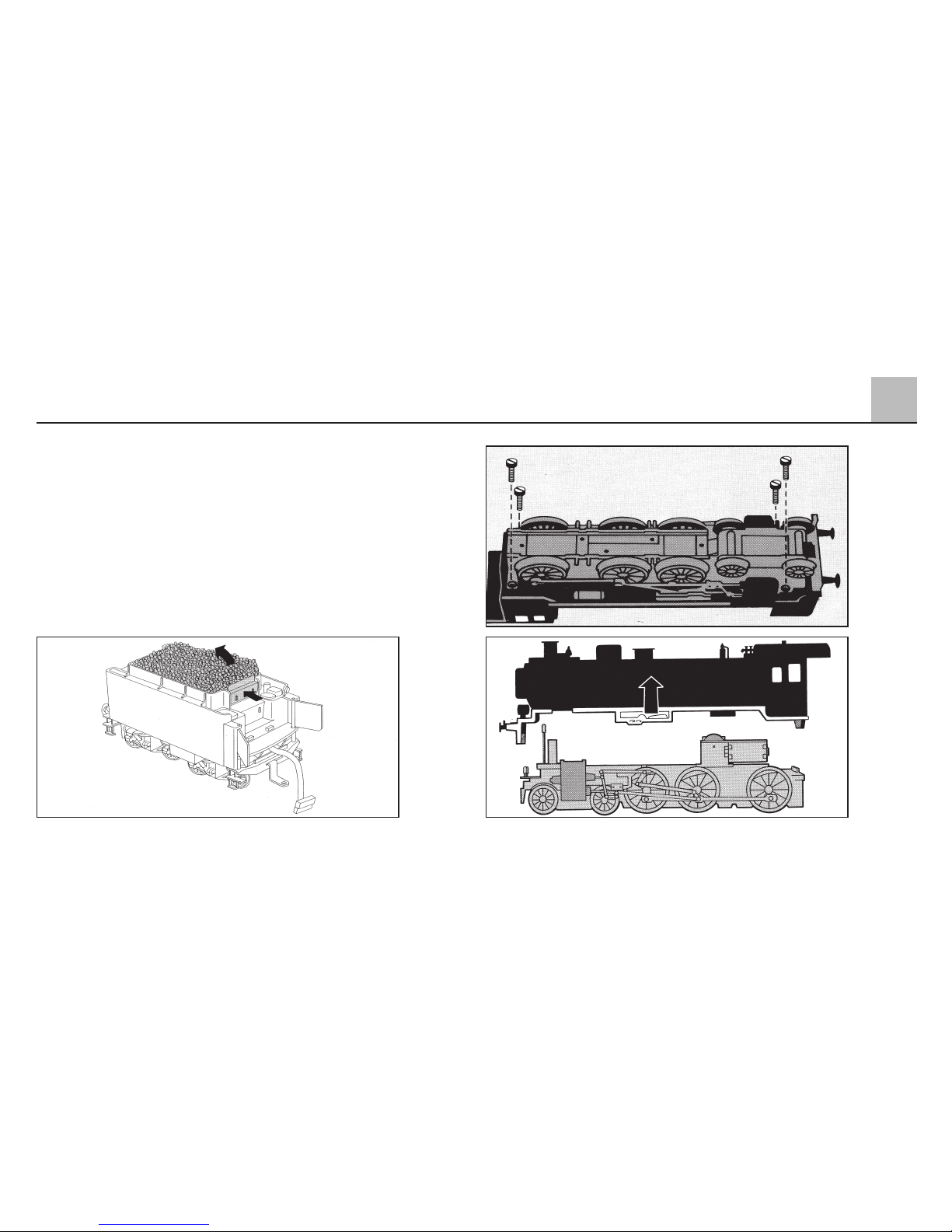
4
45
Wartung Maintenance Entretien Onderhoud
4.7 Gehäuse abnehmen
Removing the body
Démontage de la chaudière et de l’abri
Kap afnemen
Page 46
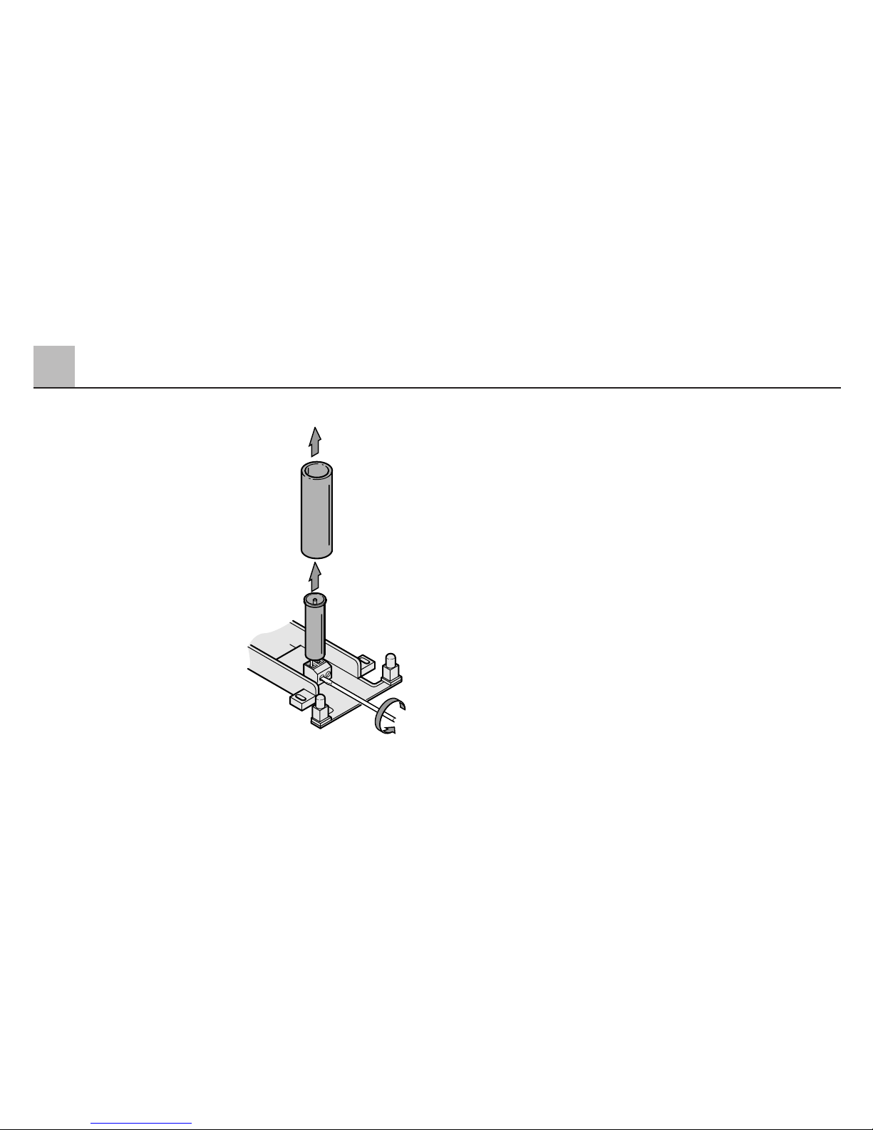
4.8 Rauchpatrone wechseln
Changing the smoke
generator
Remplacer la cartouche
fumigène
Rookpatroon vervangen
4
46
Wartung Maintenance Entretien Onderhoud
3.
2.
1.
Page 47
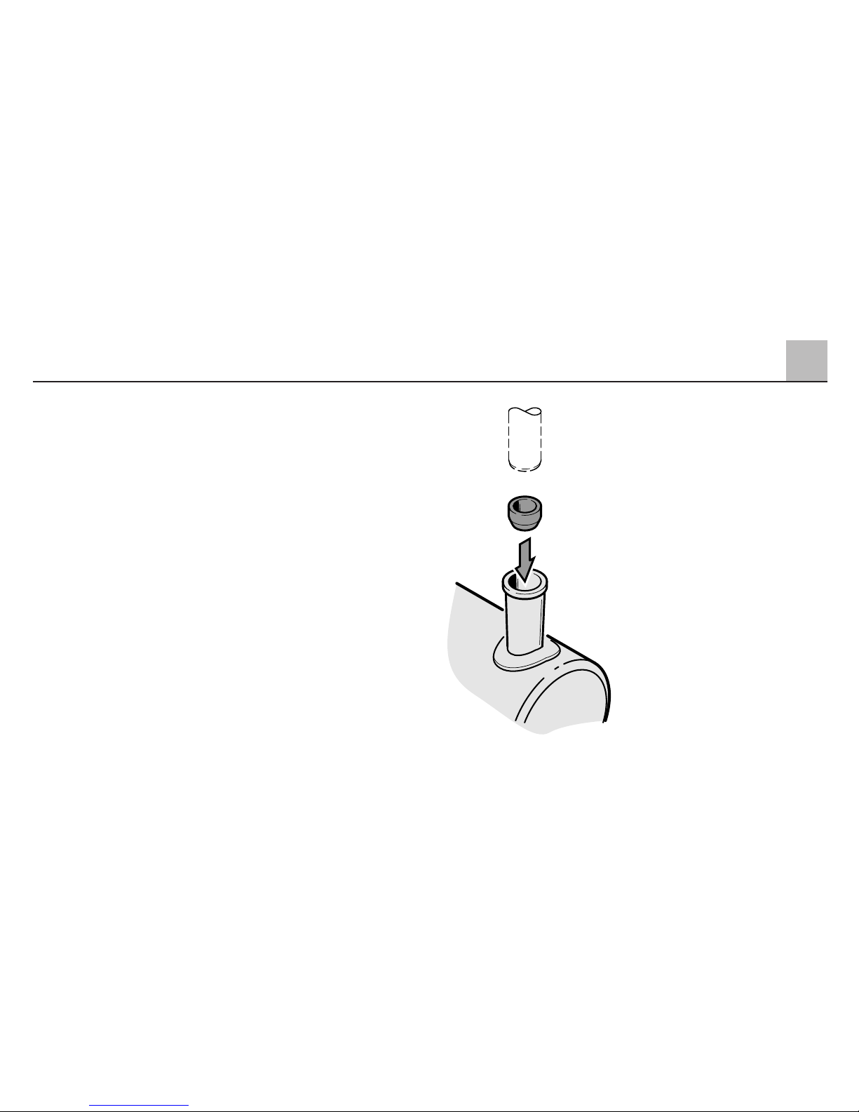
Zentrierhülse für den Rauchgenerator
durch den Schornstein von oben
wieder einsetzen.
Hinweis: Zentrierhülse für die Rauchpatrone von oben durch den Schornstein wieder einstecken.
Insert the centering sleeve for the
smoke generator into the smokestack from above.
Important: Insert the centering sleeve
for the smoke unit down into the
smoke stack from above again.
Remettre la douille de centrage
pour le fumigène par le dessus de
la cheminée.
Important: réintroudire par le haut de
la cheminée le manchon de centrage
de la cartouche de fumée.
Centreerhuls voor de rookgenerator
door de schoorsteen van bovenaf
weer inzetten.
Opmerking: De centreerhuls voor de
rookgenerator van bovenaf door de
schoorsteen steken.
47
4
Wartung Maintenance Entretien Onderhoud
Page 48
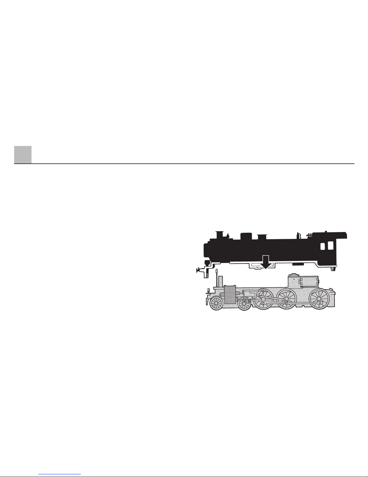
4.9 Gehäuse aufsetzen
Auf gerade Stellung der Rauchpatrone
achten.
4.9 Replacing body
Make sure that the smoke generator
is inserted straight down in the smokestack.
4.9 Remontage de la chaudière
et de l’arbi
Faire attention à bien positionner le
conduit fumigène.
4.9 Kap opzetten
Let op dat de rookgenerator recht
staat.
48
4
Wartung Maintenance Entretien Onderhoud
Page 49

4.10 Pflegehinweis
Diese Lok kann auch im Aussenbereich eingesetzt werden. Ein Betrieb
bei schlechten Witterungsbedingungen (Schnee oder Regen) wird nicht
empfohlen. Antrieb und Elektronik
sind gegen Spritzwasser geschützt.
Wasserdurchfahrten sind nicht möglich.
Es wird empfohlen, das Modell nach
dem Betrieb im Außenbereich auf
Verschmutzung zu prüfen und gegebenenfalls trocken mit Staubtuch
oder Pinsel zu reinigen. Nie die Lok
unter fließendem Wasser reinigen.
Hinweis:
Reinigungsmittel können die Farbgebung oder die Beschriftung der
Lok angreifen und beschädigen.
4.10 Tips For The Care
Of Your Locomotive
This locomotive can also be used
outdoors. We do not recommend
running the locomotive in bad weather
(snow or rain). The mechanism and
the electronic circuit are protected
against spraying water. The locomotive cannot be run through water.
We recommend that you check the
locomotive over after running in outdoors and that you dry it with a cloth
or clean in with a brush if necessary.
Never clean the locomotive with
running water.
Important:
Cleaning fluids can attack the finish
and lettering for the locomotive and
damage them.
4
49
Wartung Maintenance Entretien Onderhoud
Page 50

4.10 Remarque sur l’entretien
Cette locomotive peut également être
mise en service à l’air libre. Une utilisation par mauvais temps (neige ou
pluie) n’est pas recommandée. Le
moteur et l’électronique sont protégés
contre les projections d’eau. Des trajets dans l’eau ne sont pas possibles.
Il est recommandé de vérifier l’encrassement du modèle après une utilisation
à l’extérieur et, le cas échéant, de
nettoyer le modèle à l’aide d’un chiffon
doux ou un pinceau. Ne jamais nettoyer le modèle au jet d’eau.
Attention:
Certains solvants et produits d’entretien peuvent altérer le marquage et la
peinture du modèle.
4.10 Opmerkingen voor het
onderhoud
Deze loc kan ook buiten gebruikt
worden. Het gebruik bij slecht weer
(sneeuw of regen) is niet aan te
raden. Aandrijving en elektronica zijn
weliswaar afgeschermd tegen spatwater maar rijden door het water is
niet mogelijk.
Het is aan te bevelen het model na
het gebruik buiten te controleren op
vuil en dit eventueel droog te verwijderen met een stofdoek of een zachte
kwast. Nooit de loc onder stromend
water reinigen.
Opmerking:
Reinigingsmiddelen kunnen de lak en
de opschriften op de loc aantasten
en beschadigen.
4
50
Wartung Maintenance Entretien Onderhoud
Page 51

51
Page 52

Gebr. Märklin & Cie. GmbH
Postfach 8 60
D-73008 Göppingen
www.maerklin.com
606 918 03 02 na
Printed in Germany
Imprimé en Allemagne
Änderungen vorbehalten
This device complies with Part 15 of the FCC Rules.
Operation is subject to the following two conditions:
(1) This device may not cause harmful interference, and
(2) this device must accept any interference received, including
interference that may cause undesired operation.
 Loading...