

Page 1

Nachrüstdecoder-Set Dampf-Lok 60975
Nachrüstdecoder-Set Diesel-Lok 60976
Nachrüstdecoder-Set Elektro-Lok
60977
60975 Conversion Decoder Set for a Steam Locomotive
60976 Conversion Decoder Set for a Diesel
Locomotive
60977 Conversion Decoder Set for a Electric Locomotive
D
UK
USA
Page 2

2
Inhaltsverzeichnis Seite
Bestimmungsgemäße Verwendung 3
Lieferumfang 3
Sicherheitshinweise 3
Technische Daten 3
Funktionen 3
Decoder-Einbau 4
Multiprotokollbetrieb 6
- Brems-/Signalhalteabschnitt fx (MM), mfx, DCC 7
- Automatisches Einmessen 7
- mfx-Protokoll 8
- fx-Protokoll 8
- DCC-Protokoll 8
Physikalische Funktionen 9
Logische Funktionen 9
Decoder Funktionen und CV Einstellungen 10
Schaltbare Funktionen 11
Lautstärke ändern 14
CV-Tabelle fx (MM) 15
CV-Tabelle DCC 19
Störungen beheben 24
Entsorgung 24
Garantie 24
Table of Contents Page
Using the Product as Intended 26
Contents 26
Safety Notes 26
Technical Informatio 26
Functions 26
Decoder Installation 27
Multi-Protocol Operation 30
- Braking / Signal Stopping Block (MM), fx, mfx, DCC 30
- Automatic Calibration 30
- mfx-Protocol 31
- fx-Protocol 31
- DCC-Protocol 32
Physical Functions 33
Logic Functions 33
Decoder functions and CV settings 33
Controllable Functions 34
Volume settings 37
CV Table for fx (MM) 38
CV Table for DCC 42
Troubleshooting Problems 47
Disposing 47
Warranty 47
Page 3

3
Beim Umgang mit dem Lötkolben besteht die Gefahr von
Hautverbrennungen.
Technische Daten
• Dauerlast am Motorausgang ≤ 1,1 A
• Belastung der Lichtausgänge ≤ 250 mA
• Belastung AUX 1 – AUX 4 (Schaltausgang) je ≤ 250 mA
• Balastung AUX 3 – 4 (Logischer Ausgang) —
• Belastung AUX + Licht ≤ 300 mA
• Belastung Motor bzw. AUX 5/6 ≤ 1,1 A
• Max. Ges.-Belastung ≤ 1,6 A
• Max. Spannung ≤ 40 V
• Sound-Leistung (an 4 Ω /8 Ω) 2,75 W / 1,6 W
• Kurzschluss und Überlastschutz an den Ausgängen Licht
vorne (LV), Licht hinten (LH), AUX 1 – AUX 4 und an den
Motorausgängen.
Funktionen
Der mSD SoundDecoder, ein SoundDecoder mit sehr weit
reichenden Einstell- und Anpassungsmöglichkeiten. Zusätzliche
Sound-Funktionen stehen zur Verfügung. Der Decoder ist voll
updatefähig.
Voraussetzung hierfür ist ein entsprechendes Steuergerät (Central Station 60213/60214/60215, Software-Version 4.0 oder
höher und Programmer 60971).
Die Einstell- und Digitalfunktionen sind nur im Digitalbetrieb
anwendbar. Es stehen jedoch nicht in allen Protokollen die
gleichen Möglichkeiten zur Verfügung.
Diese Anleitung beschreibt den Einbau und die Einstellmöglich-
keiten der Decoder 60975/60976 und 60977. Sofern nicht anders
erwähnt, beziehen sich die Funktionen auf alle Decoder.
Bestimmungsgemäße Verwendung
Die Decoder 60975/60976/60977 sind zum Umrüsten von
Märklin/Trix H0-Lokomotiven.
! Nicht geeignet für Motoren mit Feldspule. Lokomotiven mit
diesen Motoren müssen mit den entsprechenden Motor-Nach-
rüstsätzen 60941, 60943 oder 60944 umgerüstet werden.
Lieferumfang
1 Decoder
1 Stecker-Platine 21 polig
1 Halteplatte
1 Schraube
1 Lautsprecher klein
1 Lautsprecher groß
1 Klebepad
Einbauanleitung
Garantieurkunde
Für den Einbau zusätzlich benötigtes Werkzeug: Schraubendreher, Pinzette und Lötstation für eine Löttemperatur bis max.
30W/300˚-400° mit dünner Spitze, Elektronik-Lötzinn (Ø 0,5-1 mm),
Entlötlitze oder Entlötsaugpumpe.
Sicherheitshinweise
• ACHTUNG! Funktionsbedingte scharfe Kanten.
• Verkabelungs- und Montagearbeiten nur im spannungslosen
Zustand ausführen. Bei nicht Beachtung kann es zu gefährlichen Körperströmen und damit zu Verletzungen führen.
• Decoder nur mit der zulässigen Spannung (siehe technische
Daten) betreiben.
Page 4

4
• Multiprotokollfähig (fx (MM), mfx, DCC und AC/DC).
• Automatische System-Erkennung. Zur Bedienung muss die
jeweils diesem System zugeordnete Adresse verwendet
werden.
• Anfahr- und Bremsverzögerung können getrennt voneinander
eingestellt werden. Kann über das Funktionsmapping jeder
beliebigen Funktionstaste zugewiesen werden.
• Typische Soundkulissen für Dampf-, Diesel- und Elektrolokomotiven.
•
Variable Motorregelung im Digital- sowie im Analogbetrieb.
• Unterstützung für 6090, 60901, DC-, Sinus- und GlockenankerMotoren. Bei Sinus-Motoren müssen CV 52 auf 1 und CV 56
auf 0 sowie CV 51 entweder auf 24 oder 0 gesetzt werden
(siehe CV Tabellen). Zusätzlich müssen Sie Aux 3 und Aux 4
jeweils auf Stand (S) und Fahrt (F) mit der Central Station oder
dem Programmer 60971 mappen.
• Funktionsmapping, siehe Hilfe in der Central Station
60213/60214/60215 oder eine ausführliche Tabelle zum Funktionsmapping nden Sie im Internet unter:
www.maerklin.de/de/produkte/tools_downloads/technische_
informationen.html
• Updatefähig mit Central Station 60213/60214/60215 (Software
Version 4.0 oder höher oder mit Programmer 60971)
• Programming on Main (PoM), diese Programmierung muss
vom Steuergerät unterstützt werden. Beachten Sie hierzu die
Bedienungsanleitung ihres Steuergerätes.
• Einstellbarer Rangiergang
• Brems- /Signalhalteabschnitt-Erkennung im Digitalbetrieb
•
Automatisches einmessen der Lokomotive mit CV7 (mfx, DCC,
MM).
Decoder-Einbau
Vor dem Einbau ist die Lokomotive auf einwandfreie mecha-
nische und elektrische Funktion zu prüfen. Gegebenenfalls muss
die Lokomotive vor dem Umbau repariert werden.
Löten Sie zuerst die Kabel an den Stromabnehmern (Schleifer),
Motor und der Beleuchtung ab. Danach bauen Sie den alten
Decoder oder Umschalter aus. Halteplatte festschrauben, Kabel
entsprechend an die Anschlüsse von Motor, Schleifer und
eventuellen Funktionen löten.
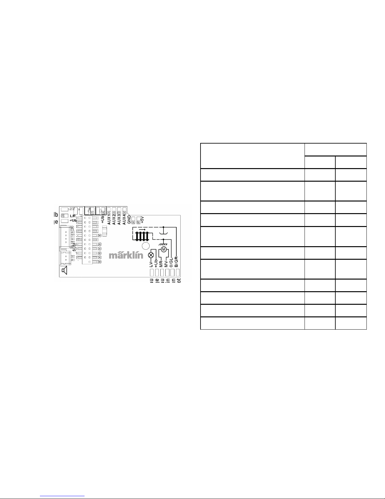
Kabelfarben entsprechen dem Märklin-Standard, Vergleichs-
tabelle zu NEM siehe Seite 5.
Wenn die Beleuchtung mit dem Rückleiter über die Fahrzeug-
masse erfolgt, kann es teilweise zum Flackern der Beleuchtung
kommen. Wenn dies nicht erwünscht ist, muss die Beleuchtung
isoliert werden. Wir empfehlen, die Glühlampe gegen die
Steckfassung 604180 und Glühlampe 610080 zu tauschen. Der
Rückleiter wird dann an das orange Kabel angeschlossen.
Wollen sie Ihr Fahrzeug nachträglich mit LED beleuchten, sind
die Kathoden (-) der LED mit dem Lichtausgang zu verbinden.
Vorwiderstand nicht vergessen! Die Anoden (+) sind an den
gemeinsamen Leiter (orange) anzuschließen.
Der gemeinsame Leiter (orange) darf nicht mit der Fahrzeugmasse
verbunden werden.
Positionieren Sie den Lautsprecher, fixieren diesen mit beilie-
gendem Klebepad und stecken das Kabel in den Steckkontakt
der Leiterplatte.
Page 5
5
gelb
orange
grau
orange
blau
grün
braun
rot
orange
orange
braun/rot
braun/grün
braun/gelb
braun/weiß
Lautsprecher
Bezeichnung Kabelfarbe
NEM Märklin
Motoranschluss 2 grau blau
2Leiter Stromabnahme Gleis links
3Leiter Stromabnahme Gleis außen
schwarz braun
Beleuchtung vorn weiß grau
Aux 1 (physikalischer Ausgang) grün braun/rot
Gemeinsamer Leiter für
Beleuchtung/Aux 1 - 4
blau orange
Beleuchtung hinten gelb gelb
2Leiter Stromabnahme Gleis rechts
3Leiter Stromabnahme Gleis Mitte
rot rot
Motoranschluss 1 orange grün
Aux 2 (physikalischer Ausgang) violett
braun/grün
Aux 3 (physikalischer Ausgang)
braun/gelb
Aux 4 (physikalischer Ausgang)
braun/weiß
Gegenüberstellung der Kabelfarben
Page 6
6
Multiprotokollbetrieb
Analogbetrieb
Der Decoder kann auch auf analogen Anlagen oder Gleisab-
schnitten betrieben werden. Der Decoder erkennt die analoge
Wechsel- oder Gleichspannung (AC/DC) automatisch und passt
sich der analogen Gleisspannung an. Es sind alle Funktionen, die
unter mfx oder DCC für den Analogbetrieb eingestellt wurden
aktiv (siehe Digitalbetrieb).
Digitalbetrieb
Die mSD SoundDecoder sind Multiprotokolldecoder. Der Decoder kann unter folgenden Digital-Protokollen eingesetzt werden:
mfx, DCC, fx (MM),
Das Digital-Protokoll mit den meisten Möglichkeiten ist das
höchstwertige Digital-Protokoll. Die Reihenfolge der DigitalProtokolle ist in der Wertung fallend:
Priorität 1: mfx
Priorität 2: DCC
Priorität 3: fx (MM)
Hinweis: Digital-Protokolle können sich gegenseitig beein-
ussen. Für einen störungsfreien Betrieb empfehlen wir, nicht
benötigte Digital-Protokolle mit CV 50 zu deaktivieren.
Deaktivieren Sie, sofern dies Ihre Zentrale unterstützt, auch dort
die nicht benötigten Digital-Protokolle.
Werden zwei oder mehrere Digital-Protokolle am Gleis erkannt,
übernimmt der Decoder automatisch das höchstwertige Digital-
Protokoll, z.B. mfx/DCC, somit wird das mfx-Digital-Protokoll vom
Decoder übernommen (siehe vorherige Tabelle).
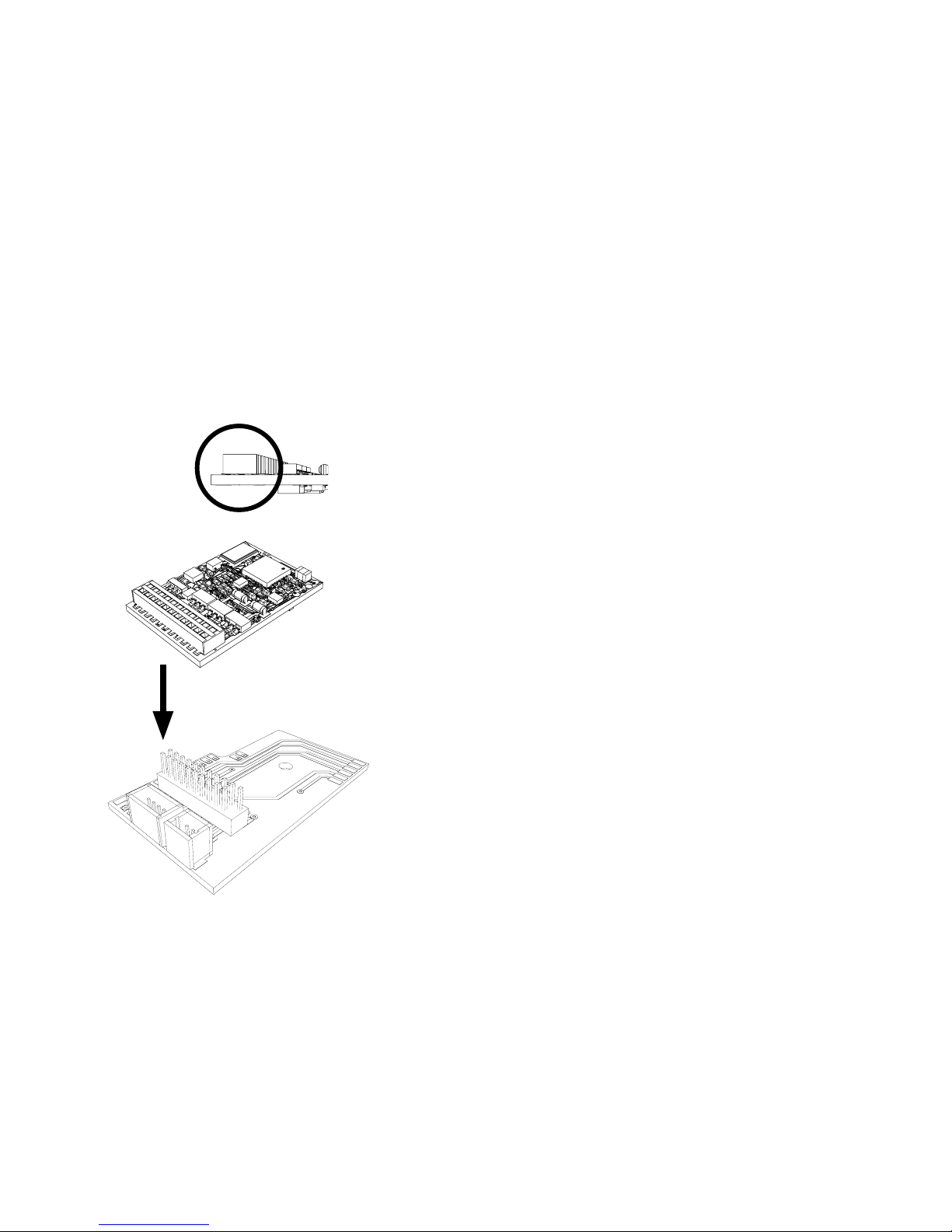
Decoder einstecken, auf richtigen Einbau achten. Modell
noch ohne Gehäuse auf dem Programmiergleis einer Prüfung
unterziehen. Wenn der Decoder einwandfrei arbeitet, kann das
Gehäuse montiert werden.
!
Page 7
7
Hinweis: Beachten Sie, dass nicht alle Funktionen in allen
Digital-Protokollen möglich sind. Unter mfx und DCC können
einige Einstellungen von Funktionen, welche im Analog-Betrieb
wirksam sein sollen, vorgenommen werden.
Brems-/Signalhalteabschnitt
fx (MM), mfx, DCC
Die Bremsmodule legen im wesentlichen eine Gleichspannung
an das Gleis. Erkennt der Decoder eine solche Gleichspannung
am Gleis, bremst er mit der eingestellten Verzögerung ab.
Erkennt der Decoder wieder ein Digital-Protokoll, beschleunigt
er auf die eingestellte Geschwindigkeit.
Soll das automatische Erkennen der Bremsstrecken angewandt
werden, wird empfohlen, den DC-Betrieb auszuschalten (siehe
CV Beschreibung). Im DCC Betrieb zusätzlich den Wert in CV 27
auf 16 oder 32 (siehe CV Tabelle) setzen.
Automatisches Einmessen für alle Protokolle
• Vor dem Einmessen muss der Motortyp ausgewählt werden
(siehe CV 52).
• Das automatische Einmessen der Lokomotive muss auf einem
geeigneten Oval ohne Hindernisse (Signale, Steigung usw.)
erfolgen. Wir empfehlen ein Oval mit Radien größer 430
mm. Die Lokomotive wird auf die maximale Geschwindigkeit
beschleunigt und kann dadurch bei kleinen Radien aus dem
Gleis kippen. Zum automatischen Einmessen der Lok gehen
Sie in die Lok-konguration der Central Station-> CV-> Info.
Im Feld Firmware überschreiben Sie die erste Ziffer mit 77. In
den Protokollen MM/DCC geben Sie im Kongurationsmodus
direkt CV7 ein. Überschreiben Sie den dort angezeigten Wert
mit der Nummer 77 und speichern es in der Lok.
Geben Sie mit dem Fahrregler eine Geschwindigkeit vor. Jetzt
startet die Lokomotive langsam und beschleunigt auf höchste
Geschwindigeit und stoppt nach kurzer Zeit. Danach macht
die Lokomotive mehrere Anfahversuche. Bleibt die Lokomotive endgültig stehen, ist das Einmessen beendet.
Während des gesamten Vorgangs sollte nicht eingegriffen
werden.
Mit Stop, drehen am Fahregler (0) oder ändern der Fahrrich-
tung kann das Einmessen abgebrochen werden, danach
muss der Vorgang wiederholt werden.
Ist das Einmessergebnis nicht zufriedenstellend kann das Einmessen mit einem anderen Motortyp wiederholt werden. Ein
mehrfaches Wiederholen ist möglich. Hat die Einmessfahrt
nicht das gewünschte Ergebnis erbracht, kann man manuell
in den Motorparametern einzelne Parameter anpassen. (MM/
DCC siehe CV Tabellen, mfx in Lok-Konguration der Central
Station-> CV-> Motor).
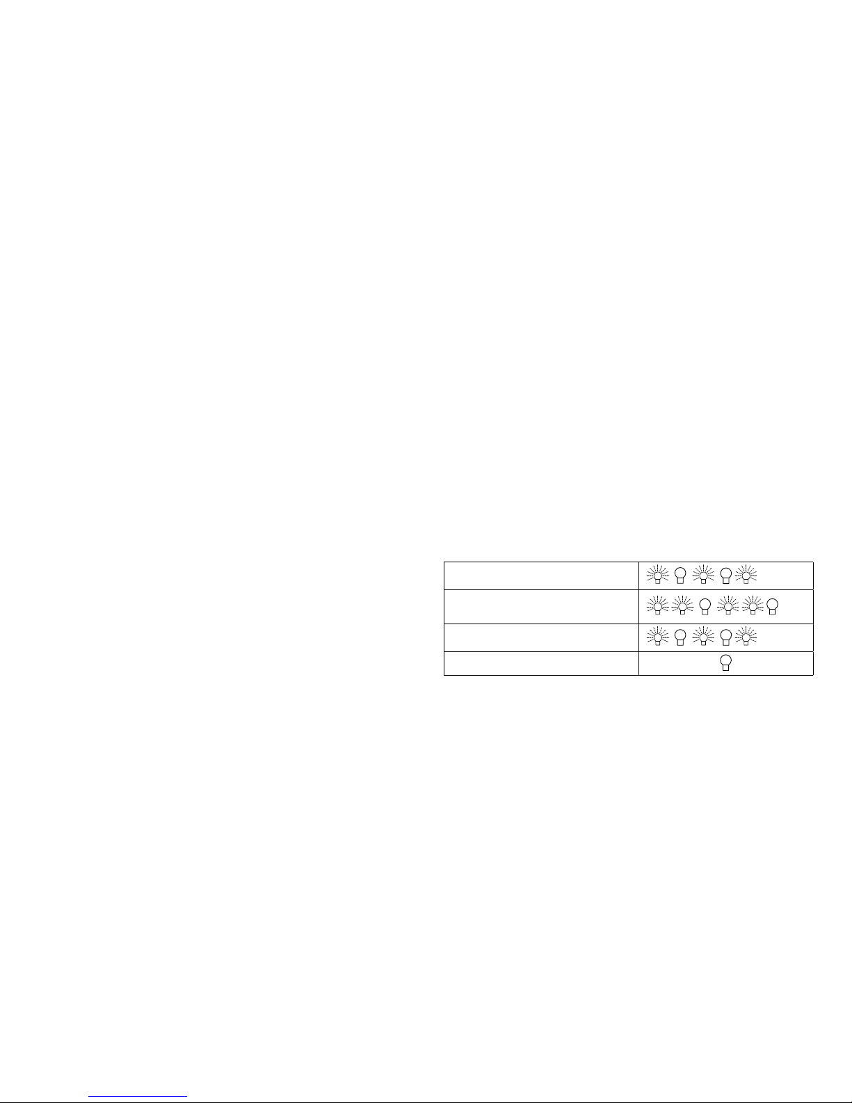
Durch folgende Lichtzeichen wird die Einmessfahrt angezeigt.
Aktiviert (Wert 77 eingegeben)
Start der Messfahrt
(Fahrstufe > 1)
Ende der Messfahrt
Abbruch oder Störung
Ausführliche Informationen hierzu im Internet: www.maerklin.de/
de/produkte/tools_downloads/technische_informationen.html
Page 8

8
• Die Folgeadressen sind ein-, ausschalt- und einstellbar und
sind manuell oder automatisch programmierbar.
• Über diese vier Adressen sind 16 Funktionen schaltbar.
Programmierung
• Die Eigenschaften des Decoders können über die Programmierung der Configuration Variablen (CV) mehrfach program-
miert werden. Das Lesen der CVs ist nicht möglich.
•
Die CV-Nummer und der CV-Wert werden direkt eingegeben.
• Programmierung der CV nur auf dem Programmiergleis.
• Die Defaulteinstellungen (Werkseinstellungen) können
wieder hergestellt werden.
• 14 bzw. 27 Fahrstufen programmierbar
• Die ersten vier Funktionen und das Licht sind über die
Hauptadresse immer schaltbar, weitere Funktionen sind in
Abhängigkeit der Folgeadressen nutzbar.
• Alle Einstellungen aus dem Funktionsmapping der mfx- oder
DCC-Programmierung werden für fx (MM) übernommen.
•
Automatische Erkennung entsprechend der aktiven Zusatzoder Folgeadressen. Erkannt wird, ob die Funktion dauerhaft
ein- bzw. ausgeschaltet oder über eine Folgeadressen
schaltbar ist. Dieses Funktionsmapping kann nur im mfx- oder
DCC-Protokoll festgelegt werden.
• Weitere Information, siehe CV-Tabelle fx-Protokoll.
DCC-Protokoll
Adressierung
• Kurze Adresse – Lange Adresse – Traktionsadresse
• Adressbereich:
1 - 127 kurze Adresse, Traktionsadresse
1 - 10239 lange Adresse
mfx-Protokoll
Adressierung
• Keine Adresse erforderlich, jeder Decoder erhält eine einma-
lige und eindeutige Kennung (UID).
• Der Decoder meldet sich an einer Central Station oder
Mobile Station mit seiner UID automatisch an.
Programmierung
• Die Eigenschaften können über die grasche Oberäche der
Central Station bzw. teilweise auch mit der Mobile Station
programmiert werden.
• Es können alle Conguration Variablen (CV) mehrfach gelesen und programmiert werden.
• Die Programmierung kann entweder auf dem Haupt- oder
dem Programmiergleis erfolgen.
• Die Defaulteinstellungen (Werkseinstellungen) können
wieder hergestellt werden.
• Funktionsmapping: Funktionen können mit Hilfe der Central
Station 60212 (eingeschränkt) und mit der Central Station
60213/60214/60215 beliebigen Funktionstasten zugeordnet
werden.
Weitere Information, siehe im Internet: www.maerklin.de/de/
produkte/tools_downloads/technische_informationen.html
fx-Protokoll (MM)
Adressierung
• 4 Adressen (eine Hauptadresse und 3 Folgeadressen)
• Adressbereich:
1 - 255 abhängig vom Steuergerät/Zentrale
• Hauptadresse ist manuell programmierbar
Page 9

9
• Jede Adresse ist manuell programmierbar.
• Kurze oder lange Adresse wird über die CVs ausgewählt.
• Eine angewandte Traktionsadresse deaktiviert die StandardAdresse.
Programmierung
• Die Eigenschaften können über die Conguration Variablen
(CV) mehrfach geändert werden.
• Die CV-Nummer und die CV-Werte werden direkt eingegeben.
• Die CVs können mehrfach gelesen und programmiert werden
(Programmierung auf dem Programmiergleis).
• Die CVs können beliebig programmiert werden (Programmierung auf dem Hauptgleis PoM). PoM ist nur bei den in der CVTabelle gekennzeichneten CV möglich. Die Programmierung
auf dem Hauptgleis (PoM) muss von Ihrer Zentrale unterstützt
werden (siehe Bedienungsanleitung ihres Gerätes).
• Die Defaulteinstellungen (Werkseinstellungen) können
wieder hergestellt werden.
• 14 bzw. 28/126 Fahrstufen einstellbar.
• Für das automatische Bremsen empfehlen wir im DCC
Betrieb den Wert in CV 27 auf 16 oder 32 (siehe Seite 20)
einzustellen.
• Alle Funktionen können entsprechend dem Funktionsmapping
geschaltet werden (siehe CV-Beschreibung).
• Weitere Information, siehe CV-Tabelle DCC-Protokoll und im
Internet (Adresse siehe Physikalische Funktionen)
Es wird empfohlen, die Programmierungen grundsätzlich auf
dem Programmiergleis vorzunehmen.
Physikalische Funktionen
Jede dieser Funktionen muss extern an die Platine angeschlossen werden. Man spricht daher von physikalischen Funktionen.
Jedem physikalischem Ausgang (AUX / Licht) kann im Digitalbetrieb ein eigener Modus/Effekt zugeordnet werden. Dazu stehen
für jeden Ausgang vier CVs zur Verfügung. Es kann für jeden
Ausgang immer nur ein Modus/Effekt eingestellt werden. Eine
ausführliche Tabelle hierzu nden sie im Internet unter:
www.maerklin.de/de/produkte/tools_downloads/technische_informationen.html
Logische Funktionen
Da diese Funktionen lediglich per Software ausgeführt werden,
wird hierfür kein physikalischer Ausgang benötigt. Deshalb
spricht man hier von einer logischen Funktion.
Anfahr-/Bremsverzögerung
• Die Beschleunigungs- und Bremszeit kann getrennt von
einander eingestellt werden.
• Die logische Funktionsabschaltung ABV kann über das
Funktionsmapping auf jede beliebige Funktionstaste gelegt
werden.
Rangiergang (RG)
• Der Rangiergang bewirkt eine Reduzierung der aktuellen
Geschwindigkeit. Dies lässt ein feinfühliges Regeln der
Lokomotive zu. Der Rangiergang kann bei mfx und DCC über
das Funktionsmapping jeder beliebigen Funktions-Taste
zugeordnet werden (siehe CV 145 Seite 22).
Page 10

10
Bahnhofsansage
Die Lok fährt erst nach beendeter Ansage an.
Türen öffnen/Türen schließen
Solange die Funktion Türen öffnen/Türen schließen aktiv ist,
fährt die Lok nicht an. Erst wenn die Funktion deaktiviert und der
Sound beendet ist, beginnt die Lok entsprechend der eingestell-
ten/aktivierten ABV zu beschleunigen.
Decoder Funktionen und CV Einstellungen
Nachfolgend finden Sie die Funktionen und die CVs in Tabellen-
form aufgeführt. Über diese CVs haben Sie die Möglichkeit eine
Vielzahl an Einstellungen und die Belegung der Funktionstasten
zu ändern.
Sie finden die CVs und ihre Anwendungen für die Gleisformate fx
(MM) und DCC in getrennten Tabellen.
Das Gleisformat mfx können Sie komfortabel über das Display
der CS 2 ab der Software Version 4.0, einstellen. Gegebenenfalls
müssen Sie oder Ihr Händler ein Update ihrer Central Station
60213/60214/60215 vornehmen.
Page 11
11
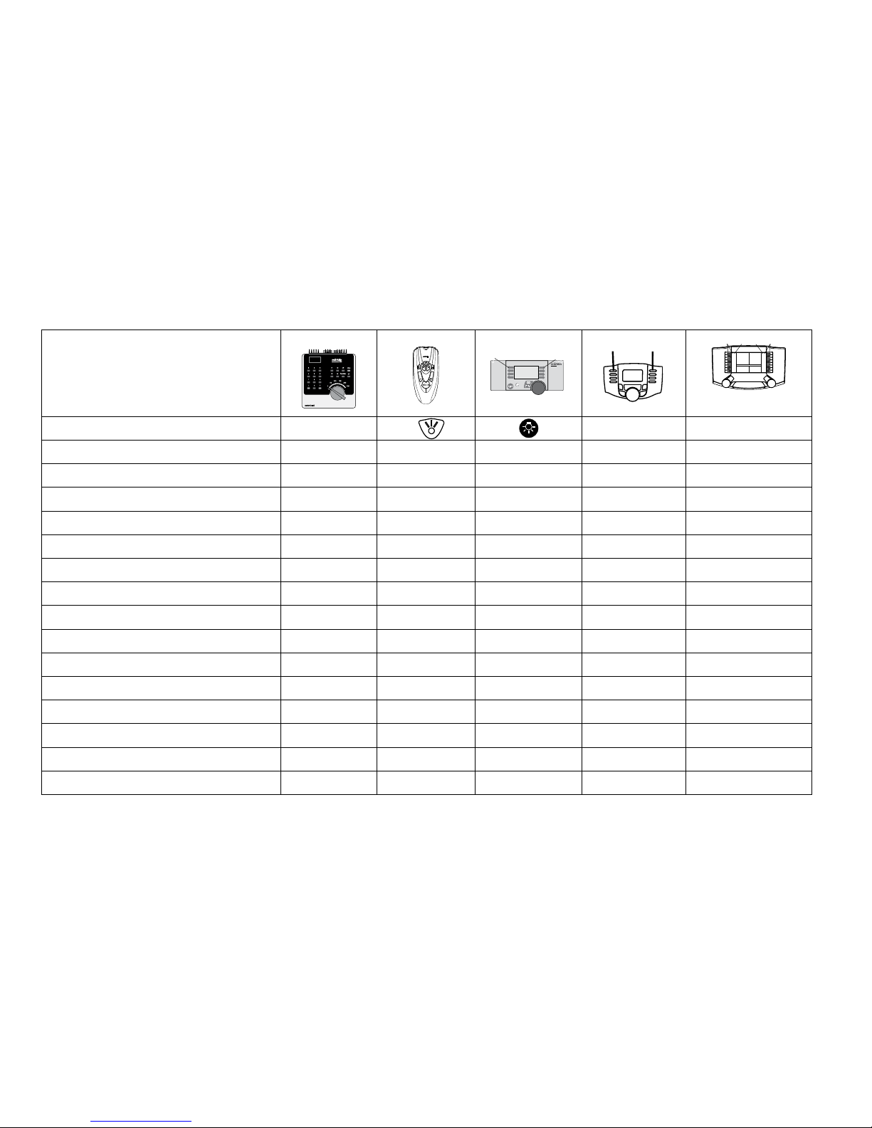
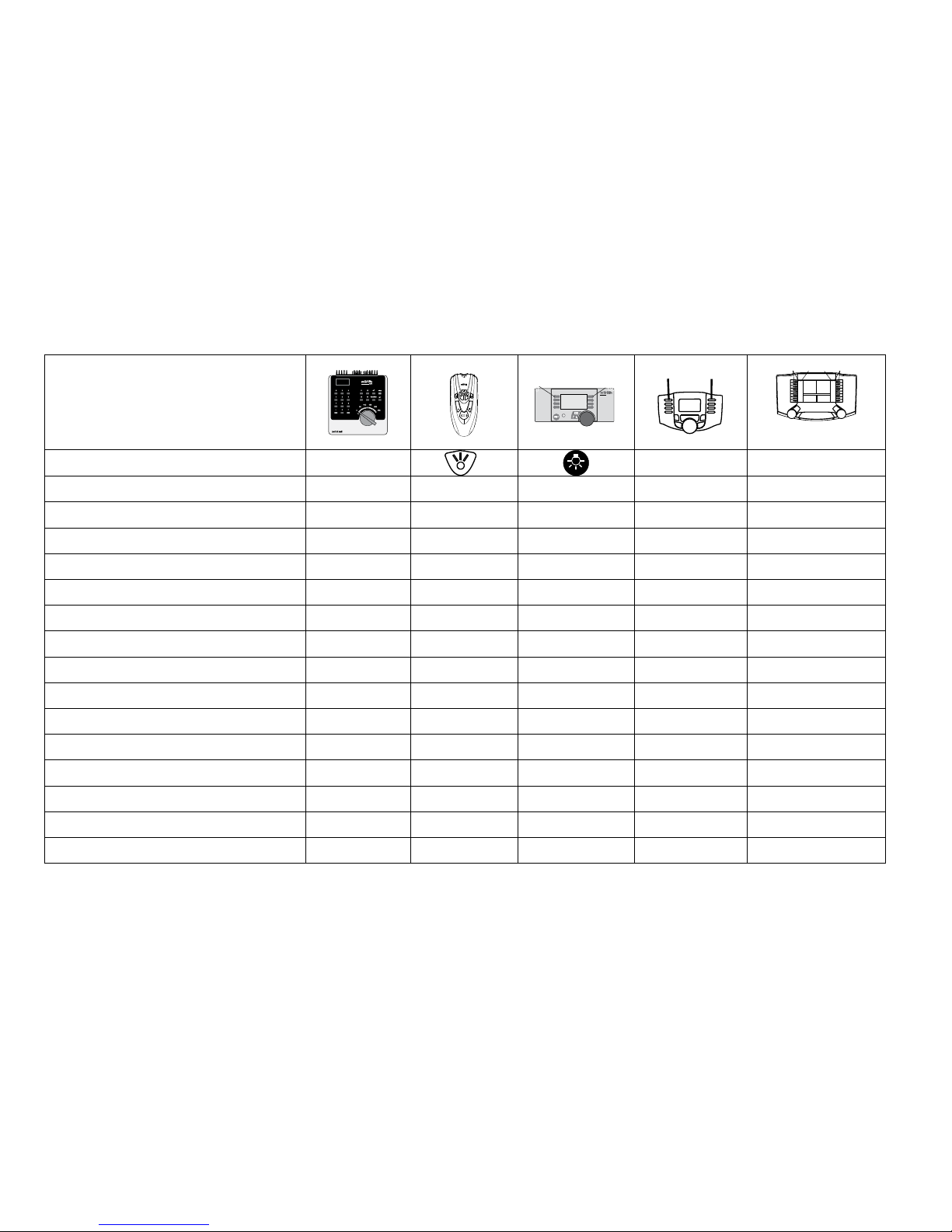
Schaltbare Funktionen
STOP
mobile station
systems
1
5
F0
F4
f0 f8 f0f8
Digital/Systems
Spitzensignal function/off Funktion f0 Funktion f0
Rauchgenerator (Aux 1) f1 Funktion 1 Funktion* Funktion f1 Funktion f1
Geräusch: Betriebsgeräusch f2 Funktion 2 Funktion * Funktion f2 Funktion f2
Geräusch: Pfeife f3 Funktion 3 Funktion * Funktion f3 Funktion f3
ABV ausschalten f4 Funktion 4 Funktion * Funktion f4 Funktion f4
Physikalisch Funktion (Aux3) —
1
—
Funktion *
Funktion f5 Funktion f5
Physikalisch Funktion (Aux4) —
1
— Funktion * Funktion f6 Funktion f6
Geräusch: Glocke —
1
— Funktion * Funktion f7 Funktion f7
Telexkupplung (Aux 2) —
1
— Funktion * Funktion f8 Funktion f8
Geräusch: Bremsenquietschen aus —
1
— — Funktion f9 Funktion f9
Geräusch: Kohle schaufeln —
1
— — Funktion f10 Funktion f10
Geräusch: Pfeife kurz —
1
— — Funktion f11 Funktion f11
Geräusch: Bahnhofsansage —
1
— — Funktion f12 Funktion f12
Geräusch: Schüttelrost —
1
— — Funktion f13 Funktion f13
Geräusch: Schienenstoß —
1
— — Funktion f14 Funktion f14
Geräusch: Schaffnerpff —
1
— — Funktion f15 Funktion f15
* Funktionen und Funktionssymbole können abweichend dargestellt sein.
1
über Folgeadressen schaltbar
Decoder 60975
Page 12
12
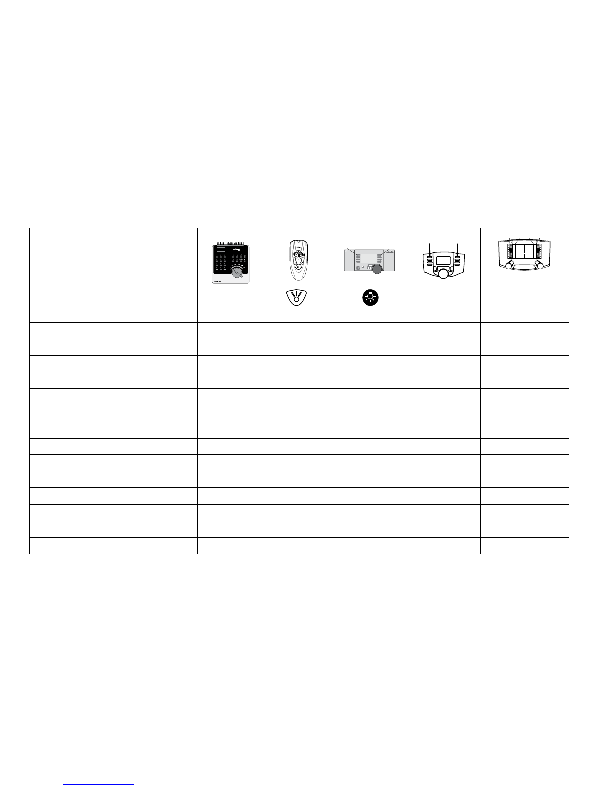
Schaltbare Funktionen
STOP
mobile station
systems
1
5
F0
F4
f0 f8 f0f8
Digital/Systems
Spitzensignal function/off
Funktion f0 Funktion f0
Führererstandsbeleuchtung (Aux1) f1 Funktion 1 Funktion * Funktion f1 Funktion f1
Geräusch: Betriebsgeräusch f2 Funktion 2 Funktion * Funktion f2 Funktion f2
Geräusch: Horn 1 f3 Funktion 3 Funktion * Funktion f3 Funktion f3
ABV ausschalten f4 Funktion 4 Funktion * Funktion f4 Funktion f4
Physikalisch Funktion (Aux 3) —
1
—
Funktion *
Funktion f5 Funktion f5
Physikalisch Funktion (Aux 4) —
1
— Funktion * Funktion f6 Funktion f6
Geräusch: Horn 2 —
1
— Funktion * Funktion f7 Funktion f7
Telexkupplung (Aux 2) —
1
— Funktion * Funktion f8 Funktion f8
Geräusch: Bremsenquietschen aus —
1
— — Funktion f9 Funktion f9
Geräusch: Lüfter —
1
— — Funktion f10 Funktion f10
Geräusch: Glocke —
1
— — Funktion f11 Funktion f11
Geräusch: Bahnhofsansage —
1
— — Funktion f12 Funktion f12
Geräusch: Hilfsdiesel —
1
— — Funktion f13 Funktion f13
Geräusch: Schienenstoß —
1
— — Funktion f14 Funktion f14
Geräusch: Schaffnerpff —
1
— — Funktion f15 Funktion f15
1
über Folgeadressen schaltbar * Funktionen und Funktionssymbole können abweichend dargestellt sein
Decoder 60976
Page 13
13
Schaltbare Funktionen
STOP
mobile station
systems
1
5
F0
F4
f0 f8 f0f8
Digital/Systems
Spitzensignal function/off
Funktion f0 Funktion f0
Führerstandsbeleuchtung (Aux 1) f1 Funktion 1 Funktion * Funktion f1 Funktion f1
Geräusch: Betriebsgeräusch f2 Funktion 2 Funktion * Funktion f2 Funktion f2
Geräusch: Horn 1 f3 Funktion 3 Funktion * Funktion f3 Funktion f3
ABV ausschalten f4 Funktion 4 Funktion * Funktion f4 Funktion f4
Physikalisch Funktion (Aux 3) —
1
—
Funktion *
Funktion f5 Funktion f5
Physikalisch Funktion (Aux 4) —
1
— Funktion * Funktion f6 Funktion f6
Geräusch: Horn 2 —
1
— Funktion * Funktion f7 Funktion f7
Telexkupplung (Aux 2) —
1
— Funktion * Funktion f8 Funktion f8
Geräusch: Bremsenquietschen aus —
1
— — Funktion f9 Funktion f9
Geräusch: Lüfter —
1
— — Funktion f10 Funktion f10
Geräusch: Pfeife —
1
— — Funktion f11 Funktion f11
Geräusch: Bahnhofsansage —
1
— — Funktion f12 Funktion f12
Geräusch: Luftpresser —
1
— — Funktion f13 Funktion f13
Geräusch: Schienenstoß —
1
— — Funktion f14 Funktion f14
Geräusch: Schaffnerpff —
1
— — Funktion f15 Funktion f15
1
über Folgeadressen schaltbar * Funktionen und Funktionssymbole können abweichend dargestellt sein.
Decoder 60977
Page 14

14
Geräusch Funktionen
Sound-Nr.
Default Wert
CV Dampf CV Diesel CV Elektro
Geräusch: Funktion f2 300 Fahrsound 300 Fahrsound 300 Fahrsound 180 0 - 255
Geräusch: Funktion f3 301 1 301 1 301 1 180 0 - 255
Geräusch: Funktion f7 303 3 302 2 302 2 180 0 - 255
Geräusch: Funktion f10 309 9 309 9 309 9 180 0 - 255
Geräusch: Funktion f11 302 2 303 3 303 3 180 0 - 255
Geräusch: Funktion f12 304 4 304 4 304 4 180 0 - 255
Geräusch: Funktion f13 310 10 307 7 308 8 180 0 - 255
Geräusch: Funktion f14 314 14 314 14 314 14 180 0 - 255
Geräusch: Funktion f15 305 5 305 5 305 5 180 0 - 255
Lautstärke gesamt (CV63) und Bremsenquitschen (CV 146) siehe folgende Tabellen
Lautstärke ändern
mfx-Protokoll: Die Gesamtlautstärke der Geräuschfunktionen lässt sich mit der Central Station 60213/60214/60215 komfortabel im
CV Menü Sound ändern. Das Funktionsmapping (zuordnen der Funktionstasten) und die individuelle Lautstärke-Einstellungen erfolgt
über die Funktionstasten. Die Sound-Nummer wird für das Funktionsmapping benötigt.
fx-Protokoll: Im fx-Protokoll kann nur die gesamte Lautstärke mit CV 63 geändert werden. Jedoch unter mfx oder DCC vorgenommen
Einstellungen werden beibehalten.
DCC-Protokoll: Zum Ändern der einzelnen Soundlautstärken müssen zuvor CV 31 auf 16 und CV 32 auf 0 geändert werden. Die
Sound-Nummer wird für das Funktionsmapping und Zuordnung der CV zum Sound benötigt.
Page 15

15
CV Bedeutung Werte Default Bemerkung
1 Adresse 1 (Hauptadresse)
1-255 (1 -
80)*
60975=78
60976=72
60977=24
Adresse ist immer aktiv und ist nicht abhän-
gig von CV 49.
2 Minimalgeschwindigkeit (Vmin)
0-255 (1 -
80)*
4
Geschwindigkeit bei kleinster Fahrstufe
Wert muß kleiner sein als Vmax, CV 5.
3 Anfahrverzögerung (AV)
0-255 (1 -
80)*
12
CV-Wert multipliziert mit 0,25 ergibt die Zeit
vom Stillstand bis Maximalgeschwindigkeit.
4 Bremsverzögerung (BV)
0-255 (1 -
80)*
12
CV-Wert multipliziert mit 0,25 ergibt die Zeit
von der Maximalgeschwindigkeit bis zm
Stillstand.
5 Maximalgeschwindigkeit (Vmax)
0-255 (1 -
63)*
{x4}*
180
Geschwindigkeit bei höchster Fahrstufe
Wert muß größer sein CV 2.
7 Einmessfahrt 77
Wert 77 eintragen. Wert 77 wird nicht dauerhaft gespeichert
8 Decoder-Reset (Default- oder Werkseinstellung) 8 Wert wird nicht geschrieben.
17 Adresse 3 (2. Folgeadresse)
0-255 (1 -
80)*
254
Adresse kann de/aktiviert werden,
in Abhängigkeit von CV 49.
18 Adresse 4 (3. Folgeadresse)
0-255 (1 -
80)*
253
Adresse kann de/aktiviert werden,
in Abhängigkeit von CV 49.
27
Bremsmodus:
Bit 0 - 3 : immer 0,
Bit 4 : DC Spg., Polarität entgegen der
Fahrtrichtung
Bit 5 : DC Spg., Polarität mit der
Fahrtrichtung
Bit 6 - 7 : immer 0
0 - 48
0
16
32
0
48
Bremsen richtungsabhängig:
- 16 normales DCC-Verhalten
- 32 inverses DCC-Verhalten
Bremsen richtungsunabhängig:
- 48 : fx/mfx - Verhalten
CV-Tabelle fx (MM)
* () = Control Unit 6021 {} = Control Unit 6021, die eingegebenen Werte werden x (Faktor) multipliziert.
Page 16

16
CV Bedeutung Werte Default Bemerkung
29
Konguration:
Bit 0 : Richtungsverhalten der Lok umkehren
0 = Richtung normal,
1 = Richtung umkehren
Bit 1 : Anzahl der Fahrstufen,
Halbstufen 14 oder 27
0 = 14 Fahrstufen,
1 = 27 Fahrstufen/Halbstufen
Bit 2 : Analogbetrieb aus-/einschalten
0 = Analog aus, 1 = Analog ein
0 - 7 6
Das Richtungsverhalten bezieht sich auf die
Fahrtrichtung und auf das Licht.
Die Anzahl der Fahrstufen und Halbstufen
sind vom Fahrgerät abhängig.
Nur Digitalbetrieb oder auch konventioneller
Betrieb. Während des Betriebes ist ein
iegender Wechsel möglich.
49
Erweiterte Konguration:
Bit 0 : Anzahl Adressen, LSB
Bit 1 : Anzahl Adressen, MSB
B i t 2 : a u t o m a t i s c h e F o l g e a d r e s s i e r u n g
(0=ein / 1=aus)
0 - 7 5
0 = eine | 1 = zwei | 0 = drei | 1 = vier
0 Adr. | 0 Adr. | 1 Adr. | 1 Adr.
0 = auto. Folge ein / 1 = auto. Folge aus
50
Alternative Formate:
Bit 0 : Analog AC aus = 0 / Analog AC ein = 1
Bit 1 : Analog DC aus = 0 / Analog DC ein = 1
Bit 2 : DCC aus = 0 / DCC ein = 1
Bit 3 : mfx aus = 0 / mfx ein = 1
0 - 15
0 / 1
0 / 2
0 / 4
0 / 8
15
Hinweis:
fx (MM) kann sich selber nicht deaktivieren.
51
Bit 0: Motor invertiert 1= ein, 0 aus
Bit 1: Licht invertiert 1= ein, 0 aus
Bit 2: Gleis invertiert 1= ein, 0 aus
Bit 3: Aux 3 (1= logischer, 0= verstärkter Ausgang)
Bit 4: Aux 4 (1= logischer, 0= verstärkter Ausgang)
0 / 1
0 / 2
0 / 4
0 / 8
0 / 16
0
Die Werte der benötigten Einstellungen
müssen addiert werden.
CV-Tabelle fx (MM)
Page 17

17
CV Bedeutung
Werte Default
Bemerkung
52
Motortyp ...
... Aux - Funktionsausgänge 5 und 6
... Motor - Softdrive Sinus
... Motor - ungeregelt
... Motor - Hochleistungsantrieb C90
... Motor - Glockenanker
... Motor - Gleichstrom DC weich
... Motor - Gleichstrom DC hart
... Motor - Gleichstrom DC Spur 1
0 - 7
0
1
2
3
4
5
6
7
5
Auswahl eines Motortyps zur weiteren
Einstellung für die Motorregelung.
oder
Auswahl zusätzlicher Funktionsausgänge bei einem H0-Decoder.
Funktionsweise der Motorausgänge
als weitere Auxe, siehe extra Tabelle1.
53 Motorregelung - Regelreferenz
0-255 (0 - 63)*
{x4}*
10 Absolutes Vmax für Motorkennlinie
54 Motorregelung - Regelparameter K
0-255 (0 - 63)*
{x4}*
20 Regelanteil K
55 Motorregelung - Regelparameter I
0-255 (0 - 63)*
{x4}*
15 Regelanteil I
56 Motorregelung - Regeleinuss
0-255 (0 - 63)*
{x4}*
63
0 = ungeregelte PWM für Sinus
(siehe auch CV 52 Motortyp)
57
Dampflok Soundabstand der Dampfstöße bei Fahrstufe 1
0-255 (0 - 63)*
{x4}*
7
ohne Radsensor
58
Dampflok Soundabstand der Dampfstöße
ab Fahrstufe 2
0-255 (0 - 63)*
{x4}*
22
ohne Radsensor
63 Lautstärke gesamt
0-255 (0 - 63)*
{x4}*
63
Gesamtlautstärke für alle Sounds.
0 = keine Sounds
CV-Tabelle fx (MM)
* () = Control Unit 6021 {} = Control Unit 6021, die eingegebenen Werte werden x (Faktor) multipliziert..
1
Eine Ausführliche Tabelle zum Funktionsmapping nden Sie im Internet unter:
www.maerklin.de/de/produkte/tools_downloads/technische_infos.html
Page 18

18
CV Bedeutung
Werte Default
Bemerkung
64 Bremsenquietschen Schwelle
0-255 (0 - 63)*
{x4}*
9
Das Quietschen beginnt, je größer der
Wert um so früher, je kleiner der Wert
um so später. Ist der Wert zu klein,
wird kein Quietschen ausgelöst.
73
Verschiedene Zustände speichern:
Bit 0 : Funktionszustände speichern
Bit 1 : Geschwindigkeit speichern
Bit 2 : Nach Reset mit/ohne ABV anfahren
0 - 7
0 / 1
0 / 2
0 / 4
7
0 = nicht speichern / 1 = speichern
0 = nicht speichern / 2 = speichern
0 = ohne ABV / 4 = mit ABV
74
Verschiedene Zustände speichern:
Bit 0 : Fahrtrichtung speichern
0 - 1 1 0 = nicht speichern / 1 = speichern
75 Adresse 2 (1. Folgeadresse)
1 - 255
(1 - 80)*
60975=79
60976=73
60977=25
Adresse kann de/aktiviert werden,
in Abhängigkeit von CV 49.
76 Analog DC Anfahrspannung
0-255 (1 - 63)*
{x4}*
12
Hinweis für die CS1: (140)
Die CS1 zeigt den Wert invertiert an.
77 Analog DC Höchstgeschwindigkeit
0-255 (1 - 63)*
{x4}*
43
78 Analog AC Anfahrspannung
0-255 (1 - 63)*
{x4}*
15
Hinweis für die CS1: (140)
Die CS1 zeigt den Wert invertiert an.
79 Analog AC Höchstgeschwindigkeit
0-255 (1 - 63)*
{x4}*
49
CV-Tabelle fx (MM)
* () = Control Unit 6021 {} = Control Unit 6021, die eingegebenen Werte werden x (Faktor) multipliziert.
Page 19

19
CV Bedeutung Werte Default Bemerkung
1 Hauptadresse 1 - 127 3
Kurze Adresse 1 - 127
Wenn CV29 / Bit 5 = 0
2
PoM
Minimalgeschwindigkeit (Vmin) 0 - 255 4
Wert muss kleiner sein als Vmax, CV 5.
(siehe CV 67)
3
PoM
Anfahrverzögerung (AV) 0 - 255 12
CV-Wert multipliziert mit 0,9 ergibt die
Zeit vom Stillstand bis Maximalgeschwindigkeit.
4
PoM
Bremsverzögerung (BV) 0 - 255 12
CV-Wert multipliziert mit 0,9 ergibt die
Zeit von Maximalgeschwindigkeit bis
Stillstand.
5
PoM
Maximalgeschwindigkeit (Vmax) 0 - 255 180
Geschwindigkeit bei höchster Fahrstufe.
Wert muss größer sein als Vmin, CV 2.
(siehe auch CV 94)
7
Einmessen
Hersteller Versionsnummer (Softwareversion)
Wert 77 eingeben. Wert 77 wird nicht
dauerhaft gespeichert
8
Hersteller Kennung / ID
Decoder-Reset (Default- oder Werkseinstellung)
–
8
131
Nur lesen
Wert kann nicht gelesen werden
13
PoM
Funktionen F1 - F8 bei alternativem Gleissignal 0 - 255
60975=1
60976=0
60977=0
0 = Fkt. MM oder Analog aus
1 = Fkt. MM oder Analog ein
Bit 7-0 [ F8 F7 F6 F5 F4 F3 F2 F1 ]
14
PoM
Funktionen FL, F9 - F15 bei alternativem Gleissignal 0 - 255 1
0 = Fkt. MM oder Analog aus
1 = Fkt. MM oder Analog ein
Bit 7-0 [ F15 F14 F13 F12 F11 F10 F9 FL ]
17 Erweiterte Adresse, höherwertige Byte 192 - 231 192
Lange Adresse 1 - 10239 (128)
Wenn CV29 / Bit 5 = 1
18 Erweiterte Adresse, niederwertige Byte 0 - 255 128
CV-Tabelle DCC
PoM muss vom Steuergerät unterstützt werden
Page 20

20
CV Bedeutung Werte Default Bemerkung
19 Traktionsadresse 0 - 255 0
1 - 127 = Traktionsadresse
0 = keine Traktion
+128, Bit 7 = Richtung umpolen bei
Traktion
21
PoM
Funktionen F1 - F8 bei Traktion 0 - 255 0
0 = Fkt. # nur für Lokadresse
1 = Fkt. # auch für Traktionsadresse
Bit 7-0 = [ F8 F7 F6 F5 F4 F3 F2 F1 ]
22
PoM
Funktionen FL, F9 - F15 bei Traktion 0 - 255 0
0 = Fkt. # nur für Lokadresse
1 = Fkt. # auch für Traktionsadresse
Bit 7-0 = [ F15 F14 F13 F12 F11 F10 F9 FL ]
27
PoM
Bremsmodus:
Bit 0 - 3 : immer 0,
Bit 4 : DC, Polarität entgegen der Fahrtrichtung
Bit 5 : DC, Polarität mit der Fahrtrichtung
Bit 6 - 7 : immer 0
0 - 48
0
0 / 16
0 / 32
0
48
Bremsen richtungsabhängig:
- 16 normales DCC-Verhalten
- 32 inverses DCC-Verhalten
Bremsen richtungsunabhängig:
- 48 : fx/mfx - Verhalten
29
PoM
Konguration:
Bit 0 : Richtungsverhalten der Lok umkehren
0 = Richtung normal,
1 = Richtung umkehren
Bit 1 : Fahrstufen 14 oder 28/128 wählen
0 = 14 Fahrstufen,
1 = 28/128 Fahrstufen
Bit 2 : Analogbetrieb aus-/einschalten
0 = Analog aus,
1 = Analog ein
Bit 5 : Kurze / Lange Adresse wählen
0 = kurze Adresse,
1 = lange Adresse
0 - 39
0
1
0
2
0
4
0
32
6
Das Richtungsverhalten bezieht sich auf
die Fahrtrichtung und auf das Licht. Die
Anzahl der Fahrstufen und das Lichtbit
sind vom Fahrgerät abhängig.
Als Lokadresse entweder die kurze
Hauptadresse oder die lange erweiterte
Adresse.
CV-Tabelle DCC
PoM muss vom Steuergerät unterstützt werden
Page 21

21
CV-Tabelle DCC
CV Bedeutung Werte Default Bemerkung
31
PoM
Index high Byte 16 16
Wird für erweiterte Einstellungen benöti-
gt, z.B. CV 300 - 328
32
PoM
Index low Byte 0 0
50
PoM
Alternative Formate:
Bit 0 : Analog AC aus = 0 / Analog AC ein = 1
Bit 1 : Analog DC aus = 0 / Analog DC ein = 1
Bit 2 : fx (MM) aus = 0 / fx (MM) ein = 1
Bit 3 : mfx aus = 0 / mfx ein = 1
0 - 15
0 / 1
0 / 2
0 / 4
0 / 8
15
Hinweis:
DCC kann sich selber nicht deaktivieren.
51
PoM
Bit 0: Motor invertiert 1= ein, 0 aus
Bit 1: Licht invertiert 1= ein, 0 aus
Bit 2: Gleis invertiert 1= ein, 0 aus
Bit 3: Aux 3 (1= logischer, 0= verstärkter Ausgang)
Bit 4: Aux 4 (1= logischer, 0= verstärkter Ausgang)
0 / 1
0 / 2
0 / 4
0 / 8
0 / 16
0
Die Werte der benötigten Einstellungen
müssen addiert werden.
52
PoM
Motortyp ... (Bit 0-4)
... Aux - Funktionsausgänge 5 und 6
... Motor - Softdrive Sinus
... Motor - ungeregelt
... Motor - Hochleistungsantrieb C90
... Motor - Glockenanker
... Motor - Gleichstrom DC weich
... Motor - Gleichstrom DC hart
... Motor - Gleichstrom DC Spur1
0 - 7
0
1
2
3
4
5
6
7
5
Auswahl eines Motortyps zur weiteren
Einstellung für die Motorregelung
oder
Auswahl zusätzlicher Funktionsausgänge
bei einem H0-Decoder. Funktionsweise
der Motorausgänge als weitere Auxe,
siehe extra Tabelle.
53
PoM
Motorregelung - Regelreferenz 0 - 255 40 Absolutes Vmax für Motorkennlinie
54
PoM
Motorregelung - Regelparameter K 0 - 255 80 Regelanteil K
55
PoM
Motorregelung - Regelparameter I 0 - 255 60 Regelanteil I
PoM muss vom Steuergerät unterstützt werden
Page 22

22
CV Bedeutung Werte Default Bemerkung
56
PoM
Motorregelung - Regeleinuss 0 - 255 255
0 = ungeregelte PWM für Sinus
(siehe auch CV 52 Motortyp)
57
PoM
Dampflok Soundabstand der Dampfstöße bei Fahrstufe 1
0 - 255 30
58
PoM
Dampflok Soundabstand der Dampfstöße ab Fahrstufe 2
0 - 255 90
63
PoM
Lautstärke gesamt 0 - 255 255
Gesamtlautstärke für alle Sounds.
0 = keine Sounds
64
PoM
Bremsenquietschen Schwelle 0 - 255 35
Das Quietschen beginnt, je größer der
Wert ist um so früher, je kleiner der Wert
ist um so später. Ist der Wert zu klein, wird
kein Quietschen ausgelöst.
66
PoM
Vorwärts Trimm 0 - 255 128
CV-Wert dividiert durch 128 ergibt
den Faktor, mit dem die Fahrstufe bei
Vorwärtsfahrt multipliziert wird.
67
PoM
-
94
PoM
Geschwindigkeitstabelle Fahrstufe 1 (Vmin)
bis
Geschwindigkeitstabelle Fahrstufe 28 (Vmax)
0 - 255
95
PoM
Rückwärts Trimm 0 - 255 128
CV-Wert dividiert durch 128 ergibt
den Faktor, mit dem die Fahrstufe bei
Rückwärtsfahrt multipliziert wird.
145
PoM
Rangiergang 0 - 128 128 128 = 50% Fahrstufe, 64 = 25% Fahrstufe
146
PoM
Sound Ausgang: Bremsenquietschen (Lautstärke) 0 - 255 180
CV-Tabelle DCC
PoM muss vom Steuergerät unterstützt werden
Page 23

23
CV-Tabelle DCC
* Eine Ausführliche Tabelle zum Funktionsmapping nden sie im Internet unter:
www.maerklin.de/de/produkte/tools_downloads/technische_informationen.html
CV Bedeutung Werte Default Bemerkung
173
PoM
Verschiedene Funktionszustände speichern:
Bit 0 : Funktionszustände speichern
Bit 1 : Geschwindigkeit speichern
Bit 2 : Nach Reset mit/ohne ABV anfahren
Bit 3 - 7 : immer 0,
0 / 1
0 / 2
0 / 4
7
0 = nicht speichern, Wert = speichern,
einzelne Werte müssen addiert werden.
174
PoM
Verschiedene Zustände speichern:
Bit 0 : Fahrtrichtung speichern
Bit 1 - 7 : immer 0
0 / 1 1
0 = nicht speichern
1 = speichern
176
PoM
Vmin Analog DC 0 - 255 50 muss kleiner CV 177 sein
177
PoM
Vmax Analog DC 0 - 255 170 muss größer CV 176 sein
178
PoM
Vmin Analog AC 0 - 255 60 muss kleiner CV 179 sein
179
PoM
Vmax Analog AC 0 - 255 190 muss größer CV 178 sein
Zum Ändern der Lautstärken (CV 300 - CV 328) muss CV 31 zuerst auf den Wert 16/ CV32 auf den Wert 0 gesetzt werden (siehe CV31)
300
PoM
301
PoM
-
328
PoM
Sound Ausgang: Lautstärke Fahrgeräusch*
Sound Ausgang: Lautstärke Sound 1*
bis
Sound Ausgang: Lautstärke Sound 16*
0 - 255
0 - 255
0 - 255
180
180
180
0 = kein Sound
PoM muss vom Steuergerät unterstützt werden
CV-Tabelle DCC
Page 24

24
Störungen beheben
Bei Betrieb mit verschiedenen Protokollen kann es zu gegenseitigen Störungen kommen. – Es wird empfohlen, die Anzahl der
Protokolle zu reduzieren. Nicht benötigte Protokolle im Lokdecoder und falls möglich auch in der Zentrale deaktivieren.
Lok ruckelt und stockt – CV Einstellung für Motorvariante prüfen,
gegebenenfalls ändern oder Reset auf die Werkseinstellungen
durchführen.
Lok fährt analog nicht - automatische Analog-Erkennung ist
deaktiviert und muss wieder aktiviert werden (siehe CV-Tabelle).
Lok (Decoder) reagiert nicht - Verkabelung und Lötstellen prüfen,
gegebenenfalls nacharbeiten. Schnittstelle des Decoders auf
festen Kontakt und Einbaurichtung prüfen.
mfx/DCC Betrieb: Auf der Anlage stehende Lokomotiven fahren
unvermittelt bei der mfx Anmeldung los. — Bei diesen Lokomotiven die automatische Analog-Erkennung deaktivieren.
Lok fährt nicht - die Funktion Türen öffnen/Türen schließen ist
noch aktiv. Funktion Türen schließen beenden, nach dem Beenden des Sounds fährt die Lok entsprechend der eingestellten
ABV an.
Entsorgung
Hinweise zum Umweltschutz: Produkte, die mit
dem durchgestrichenen Mülleimer gekennzeich-
net sind, dürfen am Ende ihrer Lebensdauer nicht
über den normalen Haushaltsabfall entsorgt
werden, sondern müssen an einem Sammelpunkt
für das Recycling von elektrischen und elek-
tronischen Geräten abgegeben werden. Das Symbol auf dem
Produkt, der Bedienungsanleitung oder der Verpackung weist
darauf hin. Die Werkstoffe sind gemäß ihrer Kennzeichnung
wiederverwertbar. Mit der Wiederverwendung, der stofichen
Verwertung oder anderen Formen der Verwertung von Altge-
räten leisten Sie einen wichtigen Beitrag zum Schutze unserer
Umwelt. Bitte erfragen Sie bei Ihrer Gemeindeverwaltung die
zuständige Entsorgungsstelle.
Garantie
Gewährleistung und Garantie gemäß der beiliegenden
Garantieurkunde.
• Für Reparaturen wenden Sie sich bitte an Ihren Märklin-
Fachhändler oder an
Gebr. Märklin & Cie. GmbH
Reparaturservice
Stuttgarter Str. 55 - 57
73033 Göppingen
Germany
Tel: 07161 608 222
E-Mail: [email protected]
Page 25

25
Page 26

26
• Operate the decoder only with the authorized voltage (see
technical data).
There is a danger of burning yourself when working with a
soldering station.
Technical Information
• Continuous current load at the motor output ≤ 1.1 amps
• Current load at the light outputs ≤ 250 milliamps
• Current load at AUX 1 - AUX 4 each ≤ 250 milliamps
• Current load at AUX 3 - AUX4 (logical output) —
• Current load AUX + light ≤ 300 milliamps
• Current load for motor and AUX 5/6 ≤ 1.1 amps
• Maximum total load ≤ 1.6 amps
• Maximum voltage ≤ 40 volts
• Sound performance (at 4 Ω /8 Ω) 2.75 watts / 1.6 watts
• Short circuit and overload protection at the outputs lights front
(LV), lights rear (LH), AUX 1 – AUX 4 and at the motor outputs.
Functions
The mSD SoundDecoder is a sound decoder with very extensive
setting and adaptation possibilities. Additional sound functions
are available. This decoder can be updated. The requirement for
this is an appropriate controller Central Station (60213 – 60215),
software Version 4.0 or higher and/or Programmer 60971).
The settings and digital functions can only be used in digital
operation. However, the same possibilities are not available in
all protocols.
These instructions describe the installation and the possible set-
tings for the 60975,90976 and 60977 decoders. Unless otherwise
Using the Product as Intended
The 60975/60976/60977 decoders are for converting
Märklin/Trix H0 locomotives to digital.
! Not suitable for motors with eld-wound coils. Locomotives
with these motors must be converted with the appropriate motor
retro t kits, item numbers 60941, 60943, or 60944.
Contents as Delivered
1 decoder
1 circuit board with a 21-pin connector
1 Circuit board retainer
1 Screw
1 speaker small
1 speaker big
1 Adhesive pad
Installation instructions
Warranty card
Tools also needed for the installation procedure include: regular
and cross-point screwdrivers, tweezers, and soldering station
with a maximum soldering temperature of up to 30 watts /
300˚Celsius / 572˚Fahrenheit with a fi ne tip, soldering fl ux for
electronics (0.5 - 1 mm / 0.02” – 0.04” diameter), de-soldering
braid or a de-soldering pump.
Safety Notes
•
WARNING! Sharp edges and points required for operation.
• Do wiring and assembly work only on a voltage-free or
grounded work mat. Failure to do this can lead to dangerous
static charge from your body and to damage to the compo-
nents.
Page 27

27
stated, the functions refer to both decoders.
•
Capable of multi-protocols (fx (MM), mfx, DCC, and AC/DC).
• Automatic system recognition. The address assigned to each
system must be used for operation.
• Acceleration and braking delay can be set separately from
each other. Any function button desired can be assigned
using the function mapping.
• Typical sound backdrops for diesel and electric locomotives
are included.
• Variable motor feedback control is available in digital as well
as in analog operation.
• 6090, 60901, DC, and can motors with bell-shaped armatures
are supported. With Sine motors, the values in CV 52 must
be set to 1, in CV 56 to 0 (see CV table). Set CV 51 either to 24
or 0. In addition, you must map Aux 3 and Aux 4 respectively
for Status (S) and Running (F) with the Central Station or the
60971 Programmer..
• Function mapping included. See Help in the Central Station
(60213-60215) or a detailed table to function mapping can be
found on the Internet at:
www.maerklin.de/de/produkte/tools_downloads/technische_
informationen.html
• Can be updated with the 60213/60214/60215 Central Station
(software version 4.0 or higher) or with the 60971 Programmer.)
• Programming on the Main (PoM) this type of programming
must be supported by the controller. Please note the instructions for your controller when doing this.
• Switching range can be set.
• Braking / signal stopping block recognition is available in
digital operation.
•
Automatic calibration of a locomotive with CV 7 (mfx, DCC, MM).
Decoder Installation
The locomotive must be checked before installing the decoder to
make sure that it (locomotive) is in good mechanical and electri-
cal condition. There are situations when the locomotive will have
to be repaired before installing the decoder.
First unsolder the wires to the current pickups (pickup shoe(s)),
motor, and the lights. After that remove the old decoder or reverse unit. Screw down the circuit board retainer and solder the
wires to the motor connections, pickup(s), and any functions.
The colors for the wires correspond to the Märklin Standard;
see Page 29 for a comparison table for NEM.
If the lights are grounded to the locomotive’s or powered rail
car’s ground on the frame, we recommend that the lights be in-
sulated from the locomotive ground. To do this, use the E604180
plug-in bulb holder(s) and E610080 light bulb(s). This will give you
icker-free lighting.
If your locomotive or powered rail car is equipped with LED lighting, then series resistors must absolutely be installed. Series
resistors differ according to the current the design. Find out the
correct values for your LEDs. You may have to ask your specialty
dealer about this.
If you want to retrofit your locomotive or powered rail car with
LEDs, the cathodes (-) on the LED are connected to the light
output on the decoder. Don’t forget series resistors! The anodes
(+) are connected to the common wire (orange).
The common ground return (orange) must not be connected to
the ground for the locomotive or powered rail car.
Page 28
28
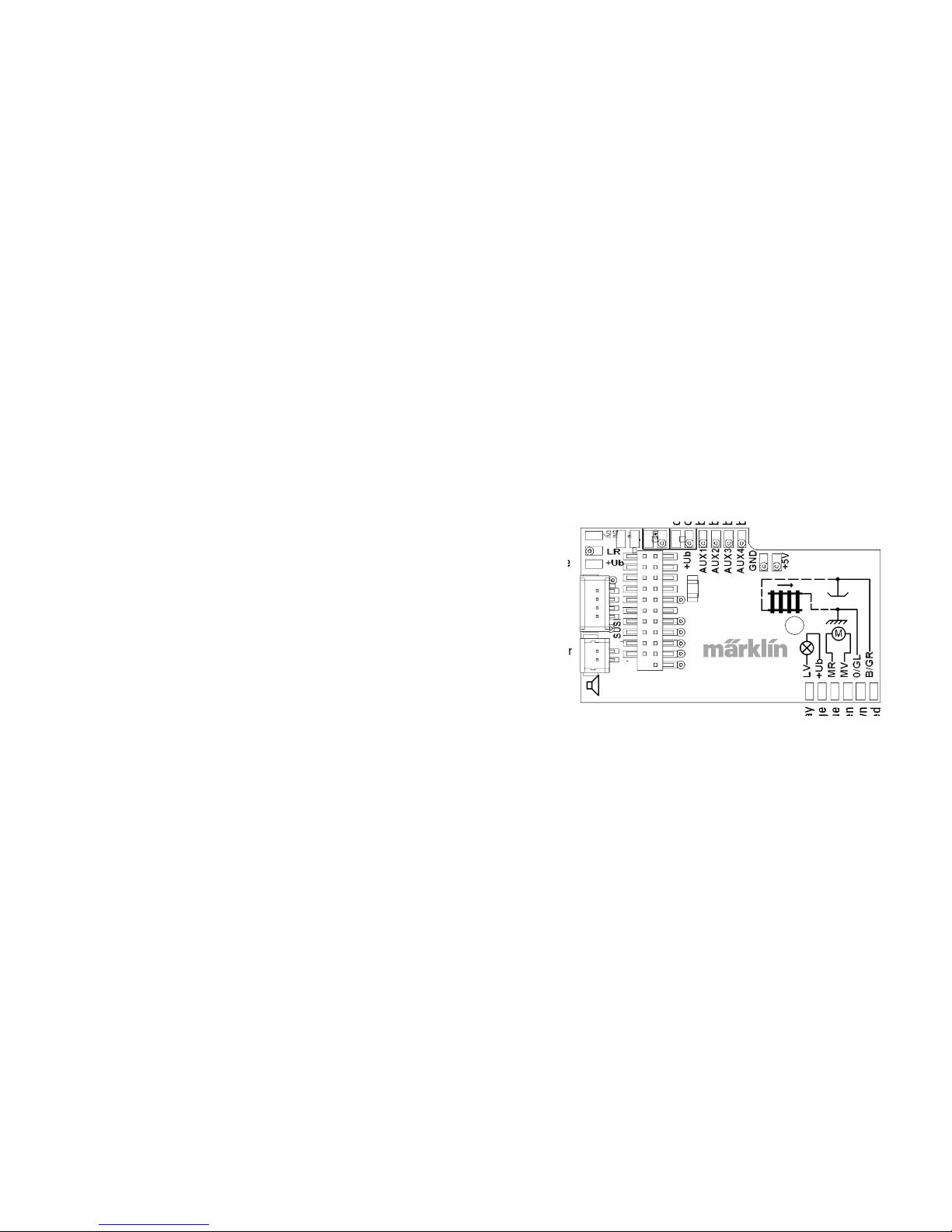
Position the speakers, fasten it with the adhesive pad and put
the cable into the connector on the circuit board.
orange
orange
brown/red
brown/green
brown/yellow
brown/wihte
yellow
orange
gray
orange
blue
green
brown
red
speaker
Page 29
29
Description Wire Color
NEM Märklin
Motor Connection 2 gray blue
Conductor Current Pickup, Track, Left
(DC) Outer (AC)
black brown
Front Lights white gray
Aux 1 (physical output) green brown/red
Common Wire for Lights /Aux 1 - 4 blue orange
Rear Lights yellow yellow
Conductor Current Pickup,
Track, Right (DC) Center (AC)
red red
Motor Connection 1 orange green
Aux 2 (physical output) violet
brown/green
Aux 3 (physical output)
brown/yellow
Aux 4 (physical output)
brown/white
Cross Referencing the Colors for the Wires
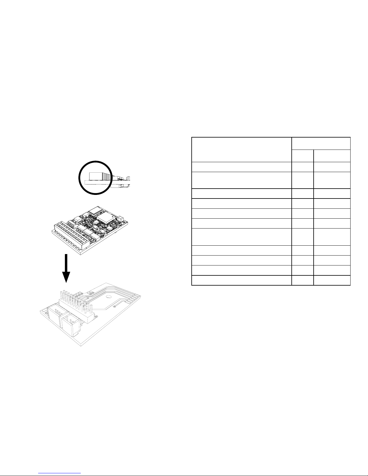
Insert the plug into the connector while paying attention to the
positioning. Place the model, without body, on the programming
track and test it. If the decoder works with no problems, the body
can be put on the locomotive.
!
Page 30

30
Multi-Protocol Operation
Analog Operation
This decoder can also be operated on analog layouts or areas of
track that are analog. The decoder recognizes alternating current or direct current voltage (AC/DC) and automatically adapts
to the analog track voltage. All functions that were set under mfx
or DCC for analog operation are active (see Digital Operation).
Digital Operation
The mSD sound decoders are multi-protocol decoders. These
decoders can be used under the following digital protocols: mfx,
DCC, fx (MM).
The digital protocol with the most possibilities is the highest
order digital protocol. The sequence of digital protocols in
descending order is:
Priority 1: mfx
Priority 2: DCC
Priority 3: fx (MM)
Note: Digital protocols can inuence each other. For trouble-free
operation, we recommend deactivating those digital protocols
not needed by using CV 50. Deactivate unneeded digital protocols at this CV if your controller supports this function.
If two or more digital protocols are recognized in the track,
the decoder automatically takes on the highest order digital
protocol, example: mfx/DCC; the decoder takes on the mfx digital
protocol (see previous table).
Note: Please note that not all functions are possible in all digital
protocols. Several settings for functions, which are supposed to
be active in analog operation, can be done under mfx and DCC.
Braking / Signal Stopping Block (MM), fx, mfx, DCC
The braking module essentially applies DC voltage to the
track. If the decoder recognizes a DC voltage of this kind in the
track, it brakes with the delay that has been set. If the decoder
recognizes a digital protocol again, it accelerates at the speed
that has been set.
If automatic recognition in braking areas is to be used, we
recommend shutting the DC operation off (see CV description).
In DCC operation setting the value in CV 27 to 16 or 32 (see CV
table).
Automatic Calibration for All Protocols
• The type of motor must be selected (see CV 52) before cali-
bration.
• Automatic calibration of a locomotive must be done on a
suitable oval of track without obstacles (signals, grades,
etc.). We recommend an oval of track with curves larger
than 430 mm / 17” in radius. The locomotive is accelerated
to the maximum speed and can therefore derail on smaller
radius curves. Go into the locomotive conguration on the
Central Station-> CV-> Info for automatic calibration of the
locomotive. In the eld Firmware, overwrite the rst digit
with 77. In the protocols MM/DCC, enter CV 7 directly in the
conguration mode. Overwrite the value displayed there with
the number 77 and store it in the locomotive.
Enter a speed with the speed control knob. Now the loco-
motive starts slowly, accelerates to the fastest speed, and
Page 31
31
mfx Protocol
Addresses
• No address is required; each decoder is given a one-time,
unique identier (UID).
• The decoder automatically registers itself on a Central Station
or a Mobile Station with its UID.
Programming
• The characteristics can be programmed using the graphic
screen on the Central Station or also partially with the Mobile
Station.
• All of the Conguration Variables (CV) can be read and
programmed repeatedly.
• The programming can be done either on the main track or the
programming track.
• The default settings (factory settings) can be produced
repeatedly.
• Function mapping: Functions can be assigned to any of the
function buttons with the help of the 60212 Central Station
(with limitations) and with the 60213/60214/60215 Central Sta-
tion (See help section in the Central Station).
For additional information, see on the Internet: www.maerklin.
de/de/produkte/tools_downloads/technische_informationen.html
fx (MM) Protocol
Addresses
•
4 addresses (a main address and 3 consecutive addresses)
• Address range:
1 - 255 depending on the controller / central controller
• The main address can be programmed manually.
then stops after a short while. After that, the locomotive tries
several times to start up. If the locomotive nally remains at a
standstill, the calibration process has ended.
No other operations should be done during the entire process.
The calibration process can be stopped with the “Stop”
button, by turning the speed control knob, by changing the
direction of travel. The process must be repeated after such a
termination.
If the results of the calibration process are not satisfactory,
calibration can be repeated with another type of motor. The
process can be repeated more than once. If the test run does
not give the desired result, you can adjust individual parameters manually in the motor parameters. (MM/DCC see CV
tables, mfx in Locomotive Configuration in the Central Station
-> CV -> Motor). The beginning and the end of the test run is
indicated by the following light symbols.
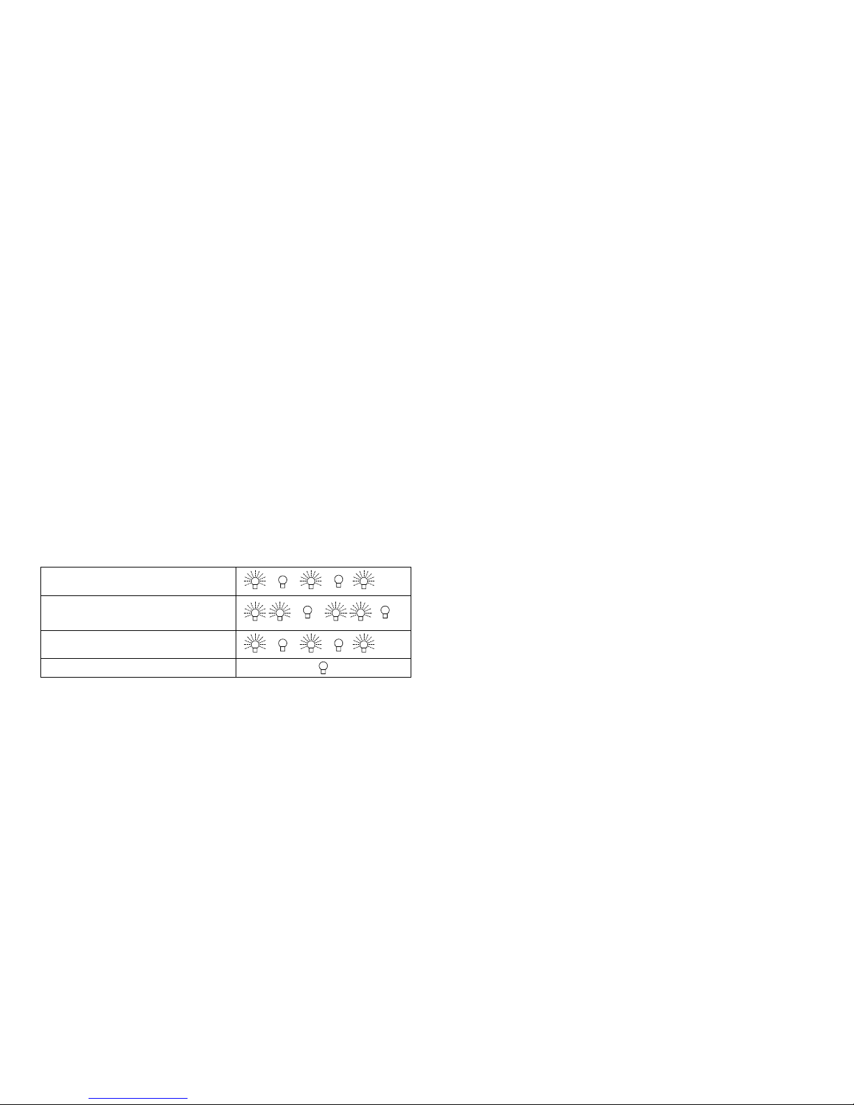
Activated (Enter the value 77)
Start of the test run
(Speed Level > 1)
End of the test run
Termination or Interruption
Extensive information about this can be found on the Internet:
www.maerklin.de/de/produkte/tools_downloads/technische_
informationen.html
Page 32

32
• The consecutive addresses can be turned on, turned off, set
and can be programmed manually or automatically.
• 16 functions can be controlled by means of the four addresses.
Programming
• The characteristics can be programmed for the decoder can
be programmed repeatedly using the programming for the
Conguration Variables (CV). Reading the CVs is not possible.
• The CV numbers and the CV values are entered directly.
• Program the CVs only on the programming track.
• The default settings (factory settings) can be produced
repeatedly.
• 14 or 27 speed levels can be programmed.
• The rst four functions and the lights can always be controlled by means of the rst address; additional functions can
be used, depending on the consecutive addresses.
• All of the settings from the function mapping for mfx or DCC
programming are taken on for fx (Motorola).
• Automatic recognition corresponding to the active additional
or consecutive addresses. What is recognized is whether
the function can be turned on or off continuously by means
of a consecutive address. This function mapping can only be
determined in the mfx or DCC protocol.
• See the CV description for the fx protocol for additional
information.
DCC Protocol
Addresses
• Short address – long address – multiple unit address
• Address range:
1 - 127 for short address and multiple unit address,
1 - 10239 for long address
• Every address can be programmed manually.
• A short or a long address is selected using the CVs.
• A multiple unit address that is being used deactivates the
standard address.
Programming
• The characteristics can be changed repeatedly using the
Conguration Variables (CV).
• The CV numbers and the CV values are entered directly.
• The CVs can be read and programmed repeatedly. (Programming is done on the programming track.)
• The CVs can be programmed in any order desired. (Programming can be done on the main track PoM). The PoM can only
be done with those designated in the CV table. Programming
on the main track PoM must be supported by your central
controller (Please see the description for this unit.).
• The default settings (factory settings) can be produced
repeatedly.
• 14/28 or 126 speed levels can be set.
• In DCC operation, we recommend setting the value in CV 27
to 16 or 32 (see Page 43) for automatic braking.
• All of the functions can be controlled according to the function mapping (see CV description).
• For additional information, see the CV table, DCC protocol,
Page 33

33
and on the Internet (see Physical Functions for the address).
We recommend that in general programming should be done on
the programming track.
Physical Functions
Each of these functions must be connected externally to the cir-
cuit board. We therefore speak of physical functions. A unique
mode/effect can be assigned to each physical output (AUX /
lights) in digital operation. Four CVs are available for each output
for this purpose. Only one mode/effect can be set for each output. A complete table for this can be found on the Internet at:
www.maerklin.de/de/produkte/tools_downloads/technische_infos.html
Logic Functions
Since these functions are only executed by software, no
physical output is required for them. We therefore speak here of
a logic function.
Acceleration/Braking Delay
• The acceleration and braking time can be set separately from
each other.
• The logic function ABV can be assigned to any function
button by using the function mapping.
Switching Range (RG)
• The switching range causes a reduction in the current speed
of the locomotive. This allows a ne touch in the controlling
the locomotive. The switching range can be assigned in mfx
and DCC to any function button by using the function mapping
(see CV 145, page 45).
Opening Doors / Closing Doors
The locomotive does not start running as long as the function
“opening doors / closing doors” is active. The locomotive starts
accelerating according to the ABV that has been set/activated
only when the function has been deactivated and the sound
has ended.
Station Announcement
The locomotive does not go until after the announcement has
ended.
Decoder functions and CV settings
The following pages have the functions and the CVs presented
in tabular form. These CVs can be given a number of settings
and can be assigned to a number of function buttons.
You‘ll nd the CVs and their applications for the track formats fx
(MM) and DCC in separate tables.
The track format mfx can be easily set by using the display
on the CS 2 with Software Version 2.0 and higher. You or your
dealer may have to install an update on your 60213/60214/60215
Central Station.
Page 34
34
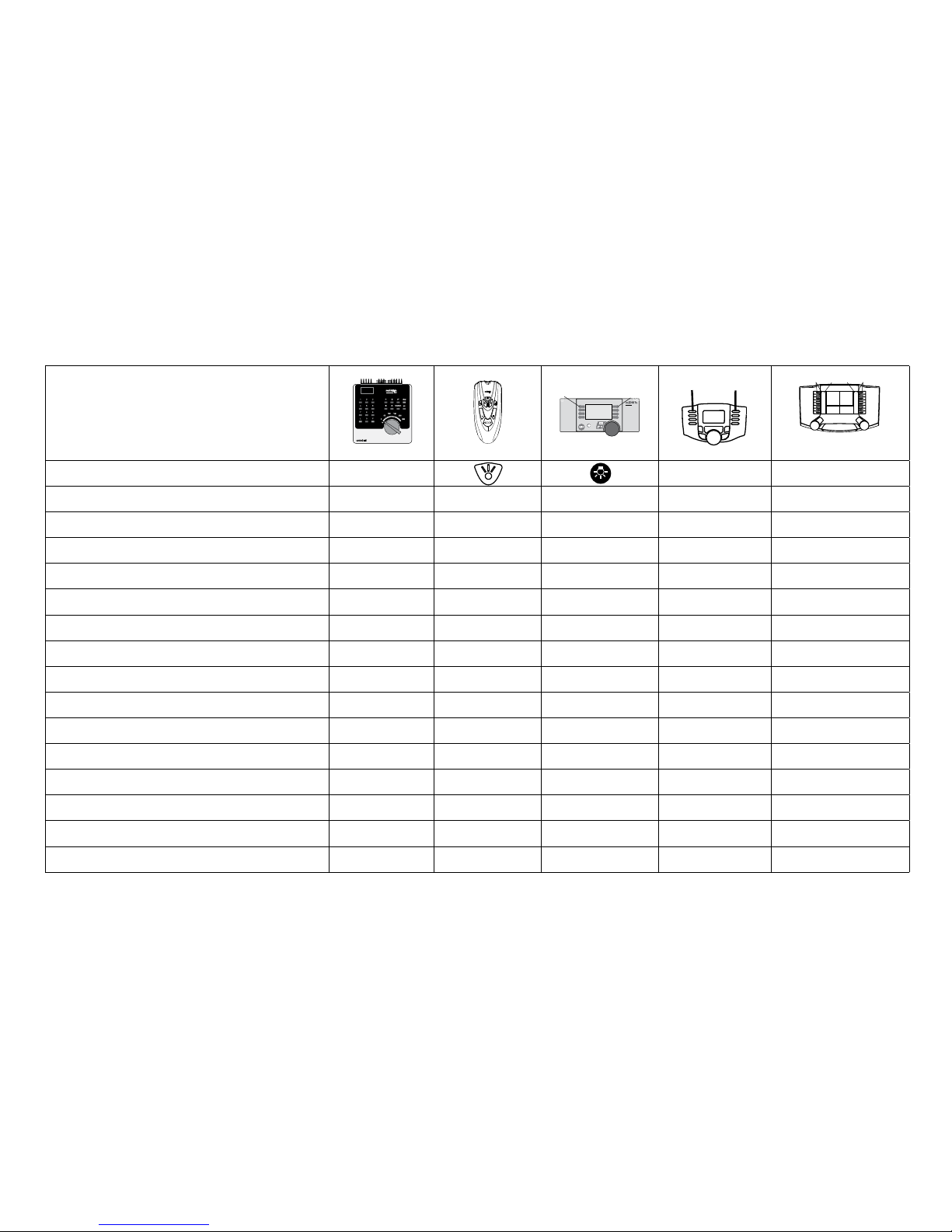
Controllable Functions
Headlights function/off Function f0 Function f0
Smoke generator (Aux1) f1 Function 1 Function * Function f1 Function f1
Sound effect: Operating sounds f2 Function 2 Function * Function f2 Function f2
Sound effect: Whistle blast f3 Function 3 Function * Function f3 Function f3
ABV off f4 Function 4 Function * Function f4 Function f4
Sound effect: Buffer to buffer —
1
—
Function *
Function f5 Function f5
Physical function (Aux 3) —
1
— Function * Function f6 Function f6
Physical function (Aux 4) —
1
— Function * Function f7 Function f7
Telex coupler (Aux 2) —
1
— Function * Function f8 Function f8
Sound effect: Squealing brakes off —
1
— — Function f9 Function f9
Sound effect: Coal being shoveled —
1
— — Function f10 Function f10
Sound effect: Short whistle blast —
1
— — Function f11 Function f11
Sound effect: Station announcements —
1
— — Function f12 Function f12
Sound effect: Rocker grate —
1
— — Function f13 Function f13
Sound effect: Rail joints —
1
— — Function f14 Function f14
Sound effect: Conductor whistle —
1
— — Function f15 Function f15
f0 f8 f0f8
STOP
mobile station
systems
1
5
Digital/Systems
F0
F4
*Function and Function symbols may be displayed in different order.
1
can be controlled by using consecutive addresses
Decoder 60975
Page 35
35
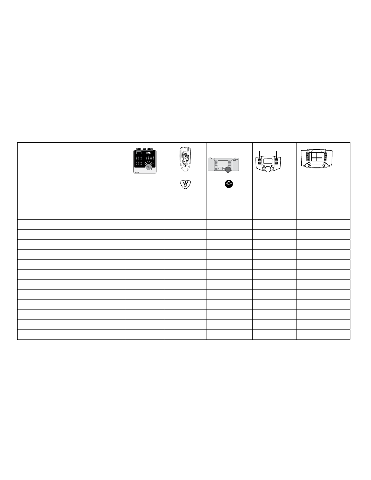
Controllable Functions
Headlights function/off Function f0 Function f0
Engineer‘s cab lighting (Aux 1) f1 Function 1 Function * Function f1 Function f1
Sound effect: Operating sounds f2 Function 2 Function * Function f2 Function f2
Sound effect: Horn 1 f3 Function 3 Function * Function f3 Function f3
ABV switching off f4 Function 4 Function * Function f4 Function f4
Physical function (Aux 3) —
1
—
Function *
Function f5 Function f5
Physical function (Aux 4) —
1
— Function * Function f6 Function f6
Sound effect: Horn 2 —
1
— Function * Function f7 Function f7
Telex coupler (Aux 2) —
1
— Function * Function f8 Function f8
Sound effect: Squealing brakes off —
1
— — Function f9 Function f9
Sound effect: Blower —
1
— — Function f10 Function f10
Sound effect: Bell —
1
— — Function f11 Function f11
Sound effect: Station announcements —
1
— — Function f12 Function f12
Sound effect: Auxiliary diesel —
1
— — Function f13 Function f13
Sound effect: Rail joints —
1
— — Function f14 Function f14
Sound effect: Conductor whistle
—
1
— — Function f15 Function f15
f0 f8 f0f8
STOP
mobile station
systems
1
5
Digital/Systems
F0
F4
Decoder 60976
*Function and Function symbols may be displayed in different order.
1
can be controlled by using consecutive addresses
Page 36
36
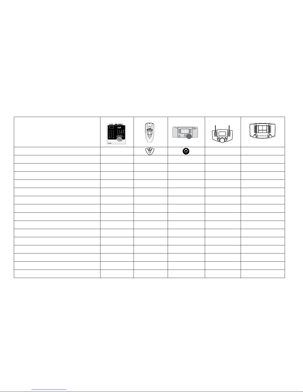
Controllable Functions
Headlights function/off Function f0 Function f0
Engineer‘s cab lighting (Aux 1) f1 Function 1 Function * Function f1 Function f1
Sound effect: Operating sounds f2 Function 2 Function * Function f2 Function f2
Sound effect: Horn 1 f3 Function 3 Function * Function f3 Function f3
ABV switching off f4 Function 4 Function * Function f4 Function f4
Physical Functions (Aux 3) —
1
—
Function *
Function f5 Function f5
Physical Functions (Aux 4) —
1
— Function * Function f6 Function f6
Sound effect: Horn 2 —
1
— Function * Function f7 Function f7
Telex coupler (Aux 2) —
1
— Function * Function f8 Function f8
Sound effect: Squealing brakes off —
1
— — Function f9 Function f9
Sound effect: Blower —
1
— — Function f10 Function f10
Sound effect: Short whistle blast —
1
— — Function f11 Function f11
Sound effect: Station announcements —
1
— — Function f12 Function f12
Sound effect: Compressor
—
1
— — Function f13 Function f13
Sound effect: Rail joints —
1
— — Function f14 Function f14
Sound effect: Conductor whistle
—
1
— — Function f15 Function f15
f0 f8 f0f8
STOP
mobile station
systems
1
5
Digital/Systems
F0
F4
Decoder 60977
*Function and Function symbols may be displayed in different order.
1
can be controlled by using consecutive addresses
Page 37

37
Sound functions
Sound-Nr.
Default Values
CV Steam CV Diesel CV Electric
Sound effect: Function f2 300 Running sounds 300 Running sounds 300 Running sounds 180 0 - 255
Sound effect: Function f3 301 1 301 1 301 1 180 0 - 255
Sound effect: Function f7 303 3 302 2 302 2 180 0 - 255
Sound effect: Function f10 309 9 309 9 309 9 180 0 - 255
Sound effect: Function f11 302 2 303 3 303 3 180 0 - 255
Sound effect: Function f12 304 4 304 4 304 4 180 0 - 255
Sound effect: Function f13 310 10 307 7 308 8 180 0 - 255
Sound effect: Function f14 314 14 314 14 314 14 180 0 - 255
Sound effect: Function f15 305 5 305 5 305 5 180 0 - 255
Total volume (CV63) and brake squeal (CV 146) see tables below.
Volume
mfx protocol: The total volume for the sound functions can be changed easily with the 60213/60214/60215 Central Station in the CV
menu “Sound”. The function mapping (assigning the function buttons) and the individual volume settings are done with the function
buttons. The sound number is required for the function mapping.
fx protocol: In the fx protocol only the total volume can be changed with CV 63. It is not possible to change the individual volumes.
However, settings done under mfx are preserved.
DCC protocol: To change the individual sound volume must be 31 CV changed to the value 16 and CV 32 to 0 before. The sound
number is required for the function mapping and for the assignment of the CVs to the sound.
Page 38

38
CV
Explanation Values Default Notes
1
Address 1 (main address) 1-255 (1 - 80)*
60975=78
60976=72
60977=24
Address is always active and is not subject
to CV 49..
2
Minimum speed (Vmin) 1-255 (1 - 80)*
4
Speed at the smallest speed level. Value
must be smaller than Vmax, CV 5.
3
Acceleration delay (AV) 1-255 (1 - 80)*
12
CV value multiplied by 0.25 gives the time
from complete stop to maximum speed.
4
Braking delay (BV) 1-255 (1 - 80)*
12
CV value multiplied by 0.25 gives the time
from Maximum speed to complete stop.
5
Maximum speed (Vmax)
1-255 (1 - 63)*
{x4}*
180
Speed at the highest speed level. Value must
be greater than CV 2.
7
Automatic Calibration
77
Enter Value 77. Value 77 is not stored
continuously.
8
Decoder reset (default or factory setting) 8 Value is not written.
17
Address 3 (2nd consecutive address) 1-255 (1 - 80)*
254
Address can be deactivated/activated
subject to CV 49.
18
Address 4 (3rd consecutive address) 1-255 (1 - 80)*
253
Address can be deactivated/activated
subject to CV 49.
27
Braking mode:
Bit 0 - 3 : always 0,
Bit 4 : DC voltage, polarity against the
direction of travel
Bit 5 : DC voltage, polarity with the direction
of travel
Bit 6 - 7 : always
0 - 48
0
16
32
0
48
Braking subject to direction:
- 16 normal DCC properties
- 32 inverse DCC properties
Braking not subject to direction:
- 48: fx/mfx properties
CV Table for fx (MM)
* () = 6021 Control Unit {} = the values entered are multiplied times “x” (factor).
Page 39

39
CV
Explanation
Values
Default
Notes
29
Conguration:
Bit 0: Reverse the locomotive’s direction properties
0 = normal direction
1 = invert direction
Bit 1: number of speed levels
half levels 14 or 27
0 = 14 speed levels
1 = 27 speed levels / half levels
Bit 2: turn analog operation on/off
0 = analog off, 1 = analog on
0 - 7
6
The direction properties refer to the direc-
tion of travel and the lights.
The number of speed levels and half levels
depend on the locomotive controller.
Only digital operation or also conventional
operation. Flipping back and forth between
the modes is possible during operation.
49
Expanded conguration:
Bit 0: number of addresses, LSB
Bit 1: number of addresses, MSB
Bit 2: automatic consecutive addressing
(on / 1=off)
0 - 7
5
0 = one | 1 = two | 0 = three | 1 = four
0 Add. | 0 Add. | 1 Add. | 1 Add.
0 = auto. sequence on / 1 = auto. sequence off
50
Alternative formats:
Bit 0: analog AC off = 0 / analog AC one = 1
Bit 1: analog DC off = 0 / analog DC on = 1
Bit 2: DCC off = 0 / DCC on = 1
Bit 3: mfx off = 0 / mfx on = 1
0 - 15
0 / 1
0 / 2
0 / 4
0 / 8
15
Note:
fx (Motorola) cannot deactivate itself
51
Bit 0: Motor inverted 1= on, 0 off
Bit 1: Light inverted 1= on, 0 off
Bit 2: Track inverted 1= on, 0 off
Bit 3: Aux 3 (1= logical, 0= amplied output)
Bit 4: Aux 4 (1= logical, 0= amplied output)
0 / 1
0 / 2
0 / 4
0 / 8
0 / 16
0
The values of the required settings must be
added up.
CV Table for fx (MM)
* () = 6021 Control Unit {} = the values entered are multiplied times “x” (factor).
Page 40

40
CV
Explanation Values Default Notes
52
Motor type ... (Bit 0-4)
... Auxiliary function outputs 5 and 6
... Motor – Softdrive Sine
... Motor – without feedback control
... Motor – High efciency propulsion C90
... Motor – Bell armature
... Motor – direct current DC soft
... Motor – direct current DC hard
... Motor – direct current DC 1 Gauge
0 - 7
0
1
2
3
4
5
6
7
5
Selection of a motor type for additional settings for motor feedback
control.
or
Selection of additional function
outputs on an H0 decoder.
See extra table
1
for how motor
outputs work as additional auxiliary
functions.
53
Motor feedback control – feedback control reference
1 - 255 (0 - 63)*
{x4}*
10
Absolute Vmax for motor characteristic
54
Motor feedback control – feedback control parameter K
1 - 255 (0 - 63)*
{x4}*
20
Feedback control portion K
55
Motor feedback control – feedback control parameter I
1 - 255 (0 - 63)*
{x4}*
15
Feedback control portion I
56
Motor feedback control – feedback control inuence
1 - 255 (0 - 63)*
{x4}*
63
0 = PWM without feedback control for
Sine (see also CV 52 motor type)
57
Steam locomotive sound interval of the steam chuffing
at speed level 1
1 - 255 (0 - 63)*
{x4}*
7
without a wheel sensor
58
Steam locomotive interval of the steam chuffing
starting at speed level 2,
1 - 255 (0 - 63)*
{x4}*
22
without a wheel sensor
63
Total volume
1 - 255 (0 - 63)*
{x4}*
63
Total volume for all sounds.
0 = no sound
CV Table for fx (MM)
* () = 6021 Control Unit {} = the values entered are multiplied times “x” (factor). * An extensive table for function mapping can be found on the Internet at:
www.maerklin.de/de/produkte/tools_downloads/technische_infos.html
Page 41

41
CV
Explanation Values Default Notes
64
Threshold for brake squealing
1 - 255 (0 - 63)*
{x4}*
9
The higher the value the sooner the
squealing begins, the lower the value
the later the squealing begins. If
the value is too low, no squealing is
activated.
73
Storing different states:
Bit 0: storing function states
Bit 1: storing speed
Bit 2: starting up with/without ABV after a reset
0 - 7
0 / 1
0 / 2
0 / 4
7
0 = do not store / 1 = store
0 = do not store / 2 = store
0 = without ABV / 4 = with ABV
74
Storing different states:
Bit 0: storing direction of travel
0 - 1
1 0 = do not store / 1 = store
75
Address 2 (1st consecutive address)
1 - 80
60975=79
60976=73
60977=25
Address can be activated/deactivated
subject to CV 49.
76
Analog DC startup voltage
1 - 63 {x4}*
12
Note for CS1: (140)
The CS1 shows this value inverted.
77
Analog DC maximum speed
1 - 63 {x4}*
43
78
Analog AC startup voltage
1 - 63 {x4}*
15
Note for CS1: (140)
The CS1 shows this value inverted.
79
Analog AC maximum speed
1 - 63 {x4}*
49
CV Table for fx (MM)
* () = 6021 Control Unit {} = the values entered are multiplied times “x” (factor).
Page 42

42
CV
Explanation Values Default Notes
1 Main address 1 - 127
3
Short address 1 - 127
If CV 29 / Bit 5 = 0
2
PoM
Minimum speed (Vmin) 0 - 255
4
Value must be lower than Wert muss
Vmax, CV 5. (see CV 67)
3
PoM
Acceleration delay (AV) 0 - 255
12
CV value multiplied by 0.9 gives the time
from being stopped to maximum speed.
4
PoM
Braking delay (BV) 0 - 255
12
CV value multiplied by 0.9 gives the time
from maximum speed to being stopped.
5
PoM
Maximum speed (Vmax) 0 - 255
180
Speed at the highest speed level.
Value must be higher than Vmin, CV 2.(see
also CV 94)
7
Automatic Calibration
Hersteller Versionsnummer (Softwareversion)
Enter Value 77. Value 77 is not stored
continuously.
8
Manufacturer identification / ID
Decoder reset (default or factory setting)
–
8
131
Read only
Value cannot be read
13
PoM
Functions F1 - F8 with an alternative track signal 0 - 255
60975=1
60976=0
60977=0
0 = Func. MM or analog off
1 = Func. MM or analog on
[ F8 F7 F6 F5 F4 F3 F2 F1 ]
14
PoM
Functions FL, F9 - F15 with an alternative track signal 0 - 255
1
0 = Func. MM or analog off
1 = Func. MM or analog on
[ F15 F14 F13 F12 F11 F10 F9 FL ]
17 Expanded address, higher value byte 192 - 231
192
Long address 1 - 10239 (128)
If CV 29 / Bit 5 = 1
18 Expanded address, lower value byte 0 - 255
128
CV Table for DCC
PoM (“Programming on Main”) must be supported by the locomotive controller / central controller.
Page 43

43
CV
Explanation Values Default Notes
19 Multiple unit address 0 - 255
0
1 - 127 = multiple unit address
0 = no multiple unit
+128, Bit 7 = reverse polarity for direction
when using multiple unit
21
PoM
Functions F1 - F8 when using multiple unit 0 - 255
0
0 = func. # only for locomotive address
1 = func. # also for multiple unit address
Bit 7-0 = [ F8 F7 F6 F5 F4 F3 F2 F1 ]
22
PoM
Functions FL, F9 - F15 when using multiple unit 0 - 255
0
0 = func. # only for locomotive address
1 = func. # also for multiple unit address
Bit 7-0 = [ F15 F14 F13 F12 F11 F10 F9 FL ]
27
PoM
Braking mode:
Bit 0 - 3 : always 0,
Bit 4 : DC voltage, polarity against the direction of travel
Bit 5 : DC voltage, polarity with the direction of travel
Bit 6 - 7 : always 0
0 - 48
0
0 / 16
0 / 32
0
48
Braking subject to direction:
- only Bit 4 : normal DC properties
- only Bit 5 : inverse DC properties
Braking not subject to direction:
- Bit 4 + 5 : 3 rail properties
29
PoM
Conguration:
Bit 0 : reverses direction properties of the locomotive
0 = normal direction, 1 = inverse direction
Bit 1 : speed level 14 or select 28/128
0 = 14 speed levels, 1 = 28/128 speed levels
Bit 2 : turn analog operation off/on
0 = analog off, 1 = analog on
Bit 5 : select short / long address
0 = short address, 1 = long address
0 - 39
0 / 1
0 / 2
0 / 4
0 / 32
6
The direction properties refer to the
direction of travel and the lights. The
number of speed levels and the light bit
depend on the locomotive controller.
Either the short main address or the
long expanded address as a locomotive
address.
CV Table for DCC
PoM must be supported by the locomotive controller / central controller.
Page 44

44
CV Table for DCC
CV
Explanation
Values
Default Notes
31
PoM
Index high Byte 16 16
This is required for advanced settings,
such as CV 300 – 328.
32
PoM
Index low Byte 0 0
50
PoM
Alternative formats:
Bit 0 : Analog AC off = 0 / Analog AC on = 1
Bit 1 : Analog DC off = 0 / Analog DC on = 1
Bit 2 : fx (MM) off = 0 / fx (MM) on = 1
Bit 3 : mfx off = 0 / mfx on = 1
0 - 15
0 / 1
0 / 2
0 / 4
0 / 8
15
Note:
DCC cannot deactivate itself.
51
PoM
Bit 0: Motor inverted 1= on, 0 off
Bit 1: Light inverted 1= on, 0 off
Bit 2: Track inverted 1= on, 0 off
Bit 3: Aux 3 (1= logical, 0= amplied output)
Bit 4: Aux 4 (1= logical, 0= amplied output)
0 / 1
0 / 2
0 / 4
0 / 8
0 / 16
0
The values of the required settings must
be added up.
52
PoM
Motor type ... (Bit 0-4)
... Auxiliary – function outputs 5 and 6
... Motor – Softdrive Sine
... Motor – without feedback control
... Motor – high-efciency C90
... Motor – bell armature
... Motor – direct current DC soft
... Motor – direct current DC hard
... Motor – direct current DC 1 Gauge
0 - 7
0
1
2
3
4
5
6
7
5
Selection of a motor type for additional
settings for motor feedback control
or
Selection of additional function outputs
on an H0 decoder. See extra table for how
motor outputs work as additional auxiliary
functions.
53
PoM
Motor feedback control – feedback control
reference
0 - 255
40
Absolute Vmax for motor characteristic
54
PoM
Motor feedback control – feedback control parameter K
0 - 255
80
Feedback control portion K
55
PoM
Motor feedback control – feedback control
parameter I
0 - 255
60
Feedback control portion I
PoM must be supported by the locomotive controller / central controller.
Page 45

45
CV Table for DCC
PoM must be supported by the locomotive controller / central controller.
CV
Explanation
Values
Default Notes
56
PoM
Motor feedback control – feedback control inuence
0 - 255
255
0 = PWM without feedback control for
Sine (see also CV 52 motor type)
57
PoM
Steam locomotive sound interval of the steam
chuffing at speed level 1
0 - 255
30
58
PoM
Steam locomotive interval of the steam chuffing
starting at speed level 2,
0 - 255
90
63
PoM
Total volume 0 - 255
255
Total volume for all sounds.
0 = no sound
64
PoM
Brake squealing threshold 0 - 255
35
The higher the value the sooner the
squealing begins, the lower the value the
later the squealing begins. If the value is
too low, no squealing is activated..
66
PoM
Forward trim 0 - 255
128
The CV value divided by 128 gives the factor with the speed level is multiplied when
the locomotive is running forward.
67
PoM
-
94
PoM
Speed table speed level 1 (Vmin) to
speed table speed level 28 (Vmax)
0 - 255
95
PoM
Reverse trim 0 - 255
128
The CV value divided by 128 gives the factor with the speed level is multiplied when
the locomotive is running in reverse.
145
PoM
Switching range 0 - 128
128
128 = 50% of speed level, 64 = 25% of
speed level
146
PoM
Sound output: Volume of squealing brakes 0 - 255
180
Page 46

46
CV Table for DCC
CV
Explanation
Values
Default Notes
173
PoM
Storing different states:
Bit 0: Storing function states
Bit 1: Storing speed
Bit 2: After a reset starting up with/without ABV
Bit 3 - 7: always 0
0 / 1
0 / 2
0 / 4
7
0 = do not store, value = store
Individual values must be added.
174
PoM
Storing different states:
Bit 0: Storing direction of travel
Bit 1 - 7: always 0
0 / 1
1
0 = do not store
1 = store
176
PoM
Vmin Analog DC 0 - 255
50
Must be smaller than CV 177
177
PoM
Vmax Analog DC 0 - 255
170
Must be larger than CV 176
178
PoM
Vmin Analog AC 0 - 255
60
Must be smaller than CV 179
179
PoM
Vmax Analog AC 0 - 255
190
Must be larger than CV 178
CV 31 must first be set to the value 16 and CV 32 to the value 0 (see CV 31) to change the volumes (CV 300 - CV 328).
300
PoM
301
PoM
-
328
PoM
Sound output: Volume of running sounds*
Sound output: Volume for Sound 1*
up to
Sound output: Volume for Sound 16*
0 - 255
0 - 255
0 - 255
180
180
180
0 = no sound
PoM must be supported by the locomotive
controller / central controller.
* An extensive table for function mapping can be found on the Internet at:
www.maerklin.de/de/produkte/tools_downloads/technische_infos.html
Page 47

47
Troubleshooting
When operating with different protocols you may have problems
in each mode at the same time. – We recommend reducing the
number of protocols. Deactivate protocols in the locomotive
decoder that are not needed and also deactivate if possible
protocols in the central controller that are not needed.
The locomotive jerks and falters – Check the CV setting for
motor variations, change if necessary, or carry out a reset to the
factory settings.
The locomotive does not run in analog. – The automatic analog
recognition is deactivated and must be activated again (see CV
table).
The locomotive (decoder) does not react. – Check the wiring and
the solder joints, redo if necessary. Check the connector for the
decoder to make sure it has permanent contact and check the
way it was installed.
mfx/DCC operation: Locomotives standing on the layout start
running suddenly during mfx registration. – Deactivate the
automatic analog recognition on these locomotives.
The locomotive does not run. – The function “open doors / close
doors” is still active. Turn off the function “close doors”; after
the sound ends the locomotive will run according to the ABV
that has been set.
Disposing
Products marked with a trash container with a
line through it may not be disposed of at the end
of their useful life in the normal household trash.
They must be taken to a collection point for the
recycling of electrical and electronic devices.
There is a symbol on the product, the operating
instructions, or the packaging to this effect. The materials in
these items can be used again according to this marking. By
reusing old devices, materially recycling, or recycling in some
other form of old devices such as these you make an important
contribution to the protection of our environment. Please ask
your city, town, community, or county authorities for the location
of the appropriate disposal site.
Warranty
The warranty card included with this product specifies the
warranty conditions.
• Please contact your authorized Märklin dealer for repairs or
contact:
U.S. only:
Märklin, Inc.
PO Box 510559
New Berlin WI 53151
Phone: 262-522-7080
Fax: 262-522-7288
Email: [email protected]
GB only
Gebr. Märklin & Cie. GmbH
Reparaturservice
Stuttgarter Str. 55 - 57
73033 Göppingen
Germany
Tel: +49 7161 608 222
E-Mail: [email protected]
Page 48
Gebr. Märklin & Cie. GmbH
Stuttgarter Str. 55 - 57
73033 Göppingen
Germany
www.maerklin.com
260057/0516/Sc2Ef
Änderungen vorbehalten
© Gebr. Märklin & Cie. GmbH
Due to different legal requirements regarding electro-magnetic compatibility, this item may
be used in the USA only after separate certication for FCC compliance and an adjustment if
necessary.
Use in the USA without this certication is not permitted and absolves us of any liability. If
you should want such certication to be done, please contact us – also due to the additional
costs incurred for this.
www.maerklin.com/en/imprint.html
Page 49

Ensemble Décodeur de mise à jour – locomotive à vapeur 60975
Ensemble Décodeur de mise à jour – locomotive diesel 60976
Ensemble Décodeur de mise à jour – locomotive électrique 60977
Inbouwdecoder-set stoomlocomotief 60975
Inbouwdecoder-set dieselloc 60976
Inbouwdecoder-set E-loc 60977
F NL
Page 50

2
Sommaire Page
Utilisation conforme à sa destination 3
Matériel fourni 3
Remarque sur la sécurité 3
Caractéristiques techniques 3
Fonctionnement 3
Installation du décodeur 4
Exploitation multiprotocole 6
- Section de freinage / d’arrêt avant un
signal fx (MM), mfx, DCC 7
- Lecture automatique pour tous les protocoles 7
- Protocole mfx 8
- Protocole fx (MM) 8
- Protocole DCC 9
Fonctions physiques 9
Fonctions logiques 10
Décodeur fonctions et les paramètres CV 10
Fonctions commutables 11
Modifier l’intensité sonore 14
Tableau des valeurs de configuration fx (MM) 15
Tableau des valeurs de configuration DCC 19
Eliminer les perturbations 24
Elimination 24
Garantie 24
Inhoudsopgave Pagina
Verantwoord gebruiken 26
Leveringsomvang 26
Veiligheidsvoorschriften 26
Technische gegevens 26
Functies 26
Decoder inbouwen 27
Multiprotocolbedrijf 29
- Afrem-/stopsectie fx (MM), mfx, DCC 30
- Automatisch inmeten voor alle protocollen 30
- mfx-protocol 31
- fx-protocol (MM) 31
- DCC-protocol 32
Fysieke functies 32
Logische functies 32
Decoder functies en CV instellingen 33
Schakelbare functies 34
Volume veranderen 37
CV-tabel fx (MM) 38
CV-tabel DCC 42
Storingen verhelpen 47
Afdanken 47
Garantie 47
Page 51

3
• N’exploiter le décodeur qu’avec la tension admissible
(voir les données techniques).
Lors du maniement du fer à souder, il y a un danger de
brûlures de la peau.
Caractéristiques techniques
• Charge permanente à la sortie moteur ≤ 1,1 A
• Charge des sorties lumière ≤ 250 mA
• Charge AUX 1 – AUX 4 respectivement ≤ 250 mA
• Charge AUX 3 – 4 (sortie logique) —
• Charge AUX + lumière (total) ≤ 300 mA
• Charge moteur, voire AUX 5/6 ≤ 1,1 A
• Charge totale max. (somme) ≤ 1,6 A
• Tension max. ≤ 40 V
• Puissance acoustique (pour 4 Ω / 8 Ω 2,75 W / 1,6 W)
• Court-circuit et protection contre les surcharges au ni-
veau des sorties lumière avant (LV), lumière arrière (LH),
AUX 1 – AUX 4 et au niveau des sorties moteur.
Fonctionnement
Le Décodeur Son mSD, un décodeur Son ayant des possibilités de paramétrage et d’adaptation très étendues. Des
fonctions Son additionnelles sont à disposition. Le décodeur
est entièrement actualisable. A cette fi n, la condition à
satisfaire est de disposer d’un contrôleur (Station centrale
60213/60214/60215, version logicielle 4.0 ou plus avec le
programmeur 60971).
Les fonctions de paramétrage et les fonctions numériques
ne sont utilisables qu’en mode numérique. Les mêmes
possibilités ne sont toutefois pas disponibles dans tous les
protocoles.
Utilisation conforme à sa destination
Les décodeurs 60975/60976/60977 sont destinés à la mise à
jour des locomotives HO Märklin/Trix.
! Ne convient pas pour des moteurs à bobine électromagné-
tique. Les locomotives équipées de ces moteurs doivent être
rééquipés avec les ensembles de mise à jour correspondants 60941, 60943 ou 60944.
Fourniture
1 Décodeur
1 Platine avec une interface à 21 pôles
1 plaque-support
1 vis
1 grands haut-parleur
1 petits haut-parleur
1 coussinet auto-collant
Instructions d’installation
Titre de garantie
Outils additionnels nécessaires pour l’installation : tournevis,
pincette et poste de brasage pour une température de brasage d’un max. de 30W/300°, avec une pointe mince, de l’étain
à braser pour composants électroniques (Ø 0,5 – 1 mm),
tresse de débrasage ou pompe aspirante de débrasage.
Remarque sur la sécurité
• ATTENTION ! Pointes et bords coupants lors du fonction-
nement du produit.
• N’effectuer les travaux de câblage et d’installation que
dans un état hors tension. L’inobservation de cette règle
peut être à l’origine de courants de choc dangereux et
donc de blessures.
Page 52

4
Ce mode d’emploi décrit l’installation et les possibilités de
réglable des décodeurs 60975, 60976 et 60977. En l’absence
d’indications contraires, les fonctions se rapportent aux
deux décodeurs.
• Capable de gérer plusieurs protocoles (fx (MM), mfx, DCC
et CA/CC).
• Identication système automatique. Pour le maniement,
il convient d’utiliser l’adresse chaque fois allouée à ce
système.
• Les retards au démarrage et au freinage peuvent être
réglés séparément. Peuvent être assignés à une quelconque touche de fonction par l’intermédiaire du mappage
des fonctions.
• Des toiles de fond sonores typiques pour des locomotives
diesel et électriques.
• Réglage moteur variable en mode numérique ainsi qu’en
mode analogique.
•
Support pour 6090, 60901, moteurs DC et induits en cloche.
Pour les moteurs sinus, la valeur de CV 52 doit être réglée sur 1, celle de CV 56 sur 0 (cf. tableau CV). CV 51 sur
24 ou 0. Vous devez également mapper Aux 3 et Aux 4 sur
Arrêt (A) et circulation (C) au moyen de la Central Station
ou du programmeur 60971.
• Mappage des fonctions, voir aide dans la station centrale
60213/60214/60215 où vous trouverez un tableau exhaustif
pour le mappage des fonctions sous www.maerklin.de/
de/produkte/tools_downloads/technische_infos.html.
• Peut être mis à jour avec la Central Station
60213/60214/60215 (version logicielle 4.1 ou plus avec le
programmeur 60971).
• Programming on Main (PoM) (programmation de la voie
principale) ; cette programmation doit être supportée par
le contrôleur. Respectez à ce propos le mode d’emploi de
votre contrôleur.
• Rapport de manœuvre paramétrable.
• Identication de la section de freinage / de signaux
d’arrêt en exploitation numérique.
• Lecture automatique de la locomotive avec le CV7 (mfx,
DCC, MM).DCC, MM).
Installation du décodeur
Avant l’installation, il convient de vérifier le fonctionnement
mécanique et électrique irréprochable de la locomotive. Le
cas échéant, il convient de réparer la locomotive avant de
procéder à la transformation.
Commencez par dessouder les câbles au niveau des pantographes (sabot de contact), du moteur et de l’éclairage.
Vous démontez ensuite l’ancien décodeur ou l’inverseur.
Visser à fond la platine de support, souder le câble de
manière appropriée aux raccordements du moteur, du sabot
de contact et d‘éventuelles fonctions.
Si l’éclairage est assuré au moyen du conducteur de
retour par l’intermédiaire de la masse du véhicule, des
scintillements pourront affecter, dans une certaine mesure,
l’éclairage. Si on juge ce phénomène indésirable, l’éclairage
doit être isolé. Nous recommandons de remplacer la lampe
à incandescence par la douille de connexion 604180 et par la
lampe à incandescence 610080.
Les couleurs des câbles correspondent au standard Märk-
lin, voir tableau comparatif sur les normes NEM en page 5.
Si votre véhicule est équipé d’un éclairage DEL, il est impératif d’installer des résistances série. Les résistances série
Page 53
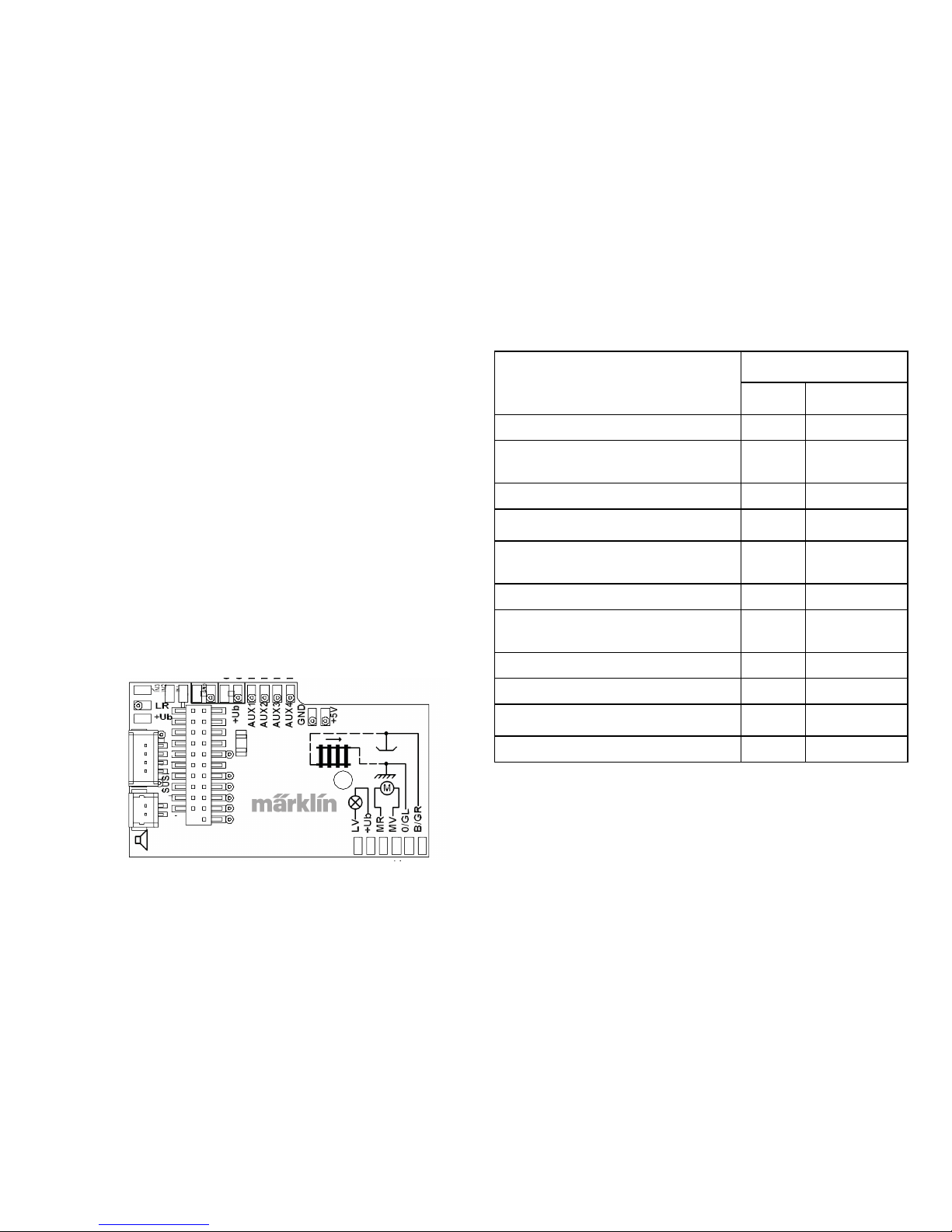
5
sont différentes en fonction du courant et de la confi guration. Déterminez les valeurs exactes pour vos DELs. Le cas
échéant, consultez à ce sujet votre commerçant spécialisé.
Si, ultérieurement vous souhaitez éclairer votre véhicule de
DELs, il conviendra de relier les cathodes (-) des DELs avec
la sortie éclairage. Ne pas oublier la résistance série ! Les
anodes (+) doivent être raccordées au conducteur (orange)
commun.
Le conducteur de retour (orange) commun ne doit pas être
relié à la masse du véhicule.
Veuillez toutefois respecter impérativement les indications
respectives se rapportant aux couleurs des câbles.
Positionner les haut-parleurs, les fi xer à l’aide du coussinet
adhésif joint et connecter le câble au circuit imprimé.
Désignation Couleur des câbles
NEM Märklin
Sortie moteur 2 grise bleue
Courant continu (DC gauche.
AC extérieur)
noire marron
Eclairage avant blanche grise
Aux 1 (sortie physique) vert marron/rouge
Conducteur commun pour l’éclairage,
Aux 1 - 4
bleu orange
Eclairage arrière jaune jaune
Courant continu (DC droite.
Centre AC)
rouge rouge
Sortie moteur 1 orange vert
Aux 2 (sortie physique) violet marron/vert
Aux 3 (sortie physique) marron/jaune
Aux 4 (sortie physique) marron/blanc
Mise en parallèle des couleurs des câbles
jaune
orange
gris
orange
bleu
vert
marron
rouge
orange
orange
marron/rouge
marron/vert
marron/jaune
marron/blanc
haut-parleur
Page 54
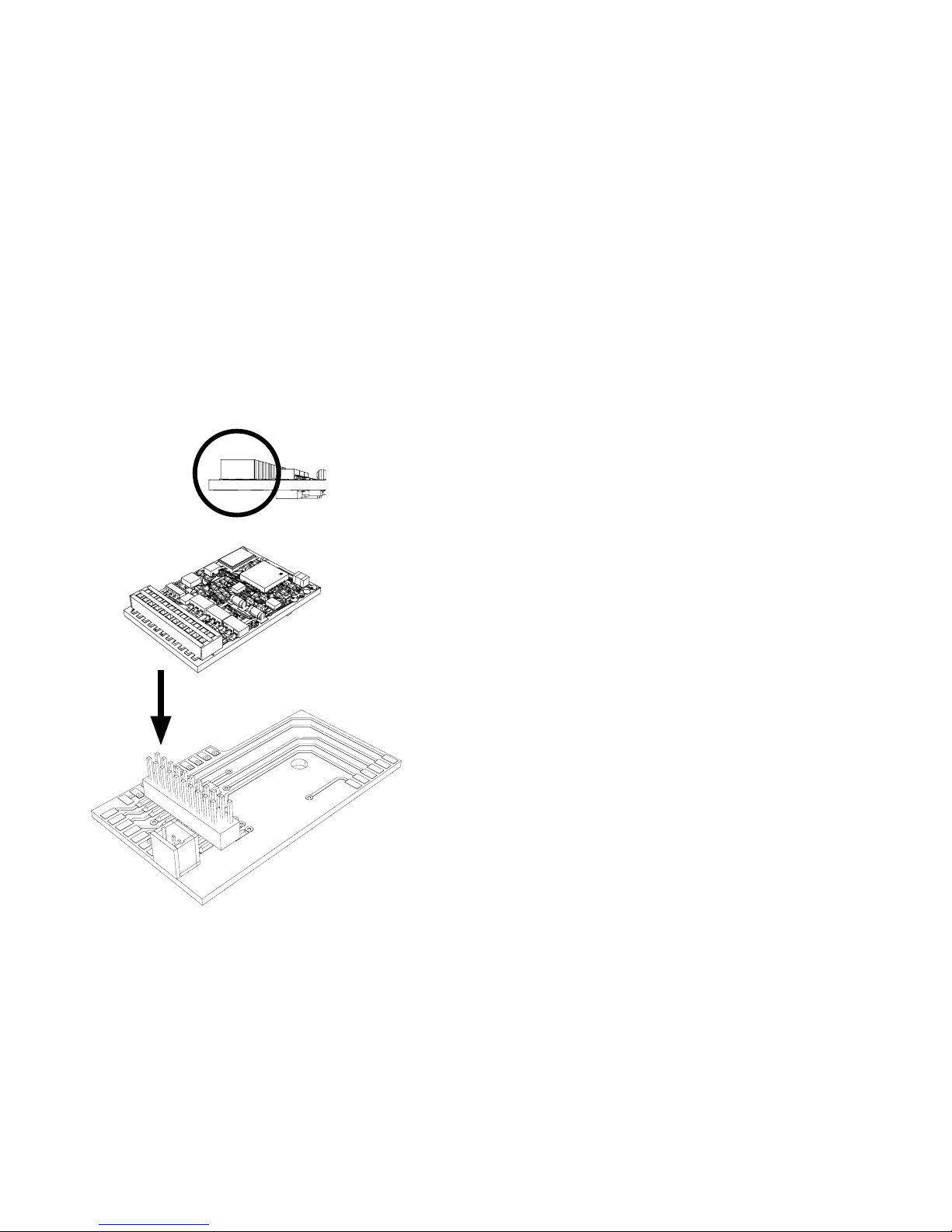
6
Mode multiprotocole
Mode analogique
On peut aussi faire fonctionner le décodeur sur des installations ou des sections de voie analogiques. Le décodeur identifi e automatiquement la tension alternative ou continue (CA/
CC) et s’adapte à la tension de voie analogique. Toutes les
fonctions qui ont été paramétrée pour le mode analogique
sous mfx ou sous DCC sont actives (voir mode numérique).
Mode numérique
Les décodeurs Son mSD sont des décodeurs multiprotocole.
Le décodeur peut être utilisé avec les protocoles numériques suivants : mfx DCC, fx (MM).
Le protocole numérique offrant les possibilités les plus
nombreuses est le protocole numérique à bit de poids
fort. La hiérarchisation des protocoles numériques est
descendante :
Priorité 1 : mfx
Priorité 2 : DCC
Priorité 3 : fx (MM)
Indication : des protocoles numériques peuvent s’infl uencer
réciproquement. Pour une exploitation sans perturbations,
nous recommandons de désactiver avec CV 50 des protocoles numériques non nécessaires.
Dans la mesure où votre centrale les supporte, désactivez y
aussi les protocoles numériques non nécessaires.
Lorsque deux ou plusieurs protocoles numériques sont
identifi és au niveau de la voie, le décodeur reprend automatiquement le protocole numérique à bit de poids fort, p. ex.
mfx/DCC. Le protocole numérique mfx est donc repris par le
Enfi cher le décodeur, veiller à une installation correctement
effectuée. Soumettre le modèle à une vérifi cation sur la
voie de programmation, encore avant qu’il soit pourvu de
sa carrosserie. Lorsque le décodeur fonctionne de manière
irréprochable, la carrosserie peut être installée.
!
Page 55
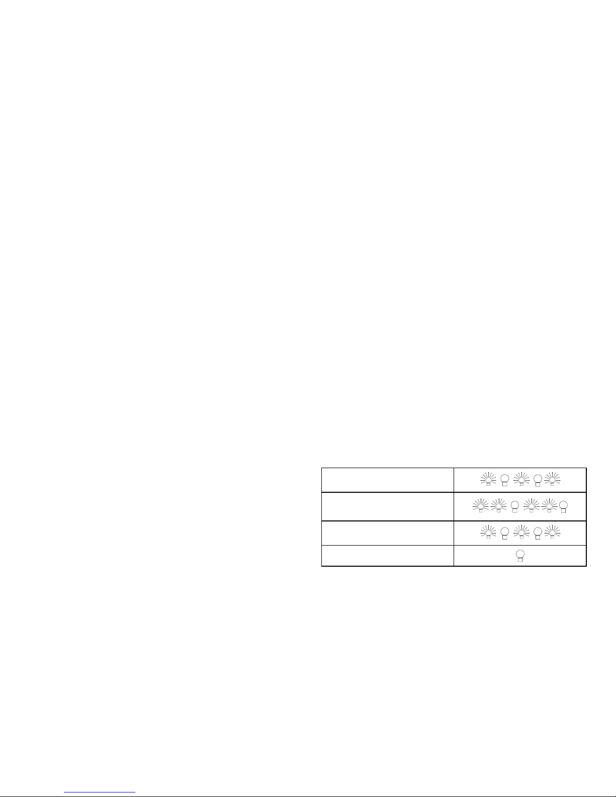
7
décodeur (voir tableau antérieur).
Indication : remarquez que toutes les fonctions ne peuvent
pas être actionnées dans tous les protocoles numériques.
Sous mfx et sous DCC, il est possible de procéder à
quelques paramétrages de fonctions devant être actives
dans le cadre de l’exploitation analogique.
Section de freinage / d’arrêt avant un
signal fx (MM), mfx, DCC
Les modules de freinage appliquent essentiellement une
tension continue sur la voie. Lorsque le décodeur identifie
une telle tension continue sur la voie, il freine avec le retard
spécifié. Lorsque le décodeur identifie de nouveau un
protocole numérique, il accélère pour parvenir à la vitesse
spécifiée.
Lorsqu’on souhaite utiliser l’identification automatique des
sections de freinage, il est recommandé de mettre hors
fonction le mode CC (voire Description des variables de
configuration (CV)).
Lecture automatique pour tous les protocoles
• Vous devez sélectionner le type de moteur avant la
lecture (cf. CV 52)
• La lecture automatique de la locomotive doit être réalisée
sur un ovale adapté sans obstacle (signaux, pente, etc.).
Nous vous recommandons d’utiliser un ovale dont le
rayon est supérieur à 430 mm. La locomotive est lancée
à la vitesse maximale et risque donc de se renverser
si vous utilisez des rayons trop petits. Pour la lecture
automatique de la locomotive, allez dans la configuration
de la locomotive de la Central Station-> CV-> Info. Dans
le champ Firmware, remplacez le premier nombre par
77. Dans les protocoles MM/DCC, indiquez directement
CV7 dans le mode de configuration. Remplacez la valeur
indiquée par 77 et enregistrez cette nouvelle valeur
dans la loco. Indiquez une vitesse à l’aide du régulateur.
La locomotive démarre lentement et accélère jusqu’à
atteindre la vitesse maximale puis s’arrête. Ensuite, la
locomotive effectue plusieurs démarrages. La lecture est
terminée lorsque la locomotive est définitivement arrêtée.
Ne touchez pendant l’opération.
Si vous touchez à la touche Stop, tournez le régulateur
de vitesse ou modifiez le sens de la marche, la lecture
risque d’être interrompue. En cas d’interruption, vous
devez reprendre toute l’opération depuis le début. Si le
résultat de la lecture n’est pas satisfaisant, vous pouvez
recommencer la lecture avec un autre type de moteur.
Vous pouvez recommencer l’opération plusieurs fois.
Si la lecture ne fournit pas le résultat escompté, vous
pouvez adapter manuellement les différents paramètres
du moteur. (MM/DCC cf. tableaux CV, mfx dans la configuration de la locomotive de la Central Station-> CV->
Moteur).
Activé (Valeur 77 enregistrée)
Début de la lecture
(vitesse > 1)
Fin de la lecture
Interruption ou panne
Page 56

8
www.maerklin.de/de/ produkte/tools_downloads/technische_informationen.html
Protocole fx (MM)
Adressage
• 4 adresses (une adresse principale et 3 adresses de
chaînage
• Champ d’adresses :
1 – 255, en fonction du contrôleur / de la centrale
• L’adresse principale est programmable manuellement.
• Les adresses de chaînage peuvent être mise en et hors
fonction et sont programmables manuellement ou automatiquement.
• Par l’intermédiaire de ces quatre adresses, les 16 fonctions sont toutes commutables.
Programmation
• Les caractéristiques du décodeur peuvent être programmées de façon réitérée par l’intermédiaire de la programmation des variables de configuration (CV). La lecture des
CVs n’est pas possible.
• Le numéro de la CV et la valeur de la CV ne sont pas
saisis directement.
• Programmation des CVs, uniquement sur la voie de
programmation.
• Les paramétrages par défaut (paramétrages usine)
peuvent être rétablis.
• 14, voire 27 crans de marche programmables.
• Les quatre premières fonctions et la lumière sont toujours
commutables par l’intermédiaire de l’adresse principale, d’autres fonctions sont utilisables en fonction des
Les signaux lumineux suivants indiquent le début et la fin de
la lecture.
Vous trouverez toutes les informations nécessaires pour
cela sur Internet: www.maerklin.de/de/produkte/tools_
downloads/technische_informationen.html
Protocole mfx
Adressage
• Aucune adresse n’est nécessaire, le décodeur reçoit toutefois une identification unique et non équivoque (UID).
• Avec son UID, le décodeur indique automatiquement
à une station centrale ou à une station mobile qu’il est
connecté.
Programmation
• Les caractéristiques peuvent être programmées par
l’intermédiaire de la couche graphique de la station centrale, voire en partie aussi au moyen de la station mobile.
• Toutes les congurations variables (CV) peuvent être lues
et programmées de façon réitérée.
• La programmation peut être réalisée soit sur la voie
principale, soit sur la voie de programmation.
• Les paramétrages par défaut (paramétrages usine)
peuvent être rétablis.
• Mappage des fonctions : les fonctions peuvent être
affectées à de quelconques touches de fonction au
moyen de la station centrale (60212) (restreinte) et avec
la station centrale 60213/60214/60215 (voir Aide au niveau
de la station centrale).
Vous trouverez d‘autres Informations sur Internet :
Page 57

9
Fonctions physiques
Chacune de ces fonctions doit être raccordée, extérieurement, à la platine. C’est la raison pour laquelle on parle de
fonctions physiques. En mode numérique, il est possible
d’affecter à chaque sortie physiques (AUX / lumière), un
mode/effet propre. Chaque sortie dispose pour cela de
quatre CV. A cette fin, trois CVs sont disponibles pour
chaque sortie. Pour chaque sortie, seul un mode/effet
pourra chaque fois être paramétré. Vous trouverez, sur
internet, un tableau détaillé à ce sujet à l’adresse
adresses de chaînage.
• Tous les paramétrages provenant du mappage des fonc-
tions de la programmation mfx ou DCC sont repris pour fx
(MM).
• Identication automatique en fonction des adresses
additionnelles ou de chaînage actives. Est identifié, si la
fonction est mise en, voire hors fonction durablement.
Ce mappage de fonction ne peut être arrêté que dans le
cadre du protocole mfx ou DCC.
• Pour toute information complémentaire, voir le protocole
fx du tableau des CV.
Protocole DCC
Adressage
• Adresse brève – adresse longue – adresse de traction.
• Champ d’adresse :
1 – 127 adresse brève, adresse de traction
1 – 10239 adresse longue
• Chaque adresse est programmable manuellement.
• L’adresse brève ou longue est choisie par l’intermédiaire
des CVs.
• Une adresse de traction utilisée désactive l’adresse
standard.
Programmation
• Les caractéristiques peuvent être modiées de façon
réitérée par l’intermédiaire des variables de configuration
(CVs).
• Toutes les congurations variables (CV) peuvent être lues
et programmées de façon réitérée.
• La programmation peut être réalisée soit sur la voie
principale, soit sur la voie de programmation.
• Les CVs peuvent être programmées librement (programmation de la voie principale (PoM). La PoM n’est possible
que pour les CVs identifiées dans le tableau des CVs.
La programmation sur la voie principale (PoM) doit être
supportée par votre centrale (voir mode d’emploi de votre
appareil).
• Les paramétrages par défaut (paramétrages usine)
peuvent être rétablis.
• 14/28, voire 126 crans de marche sont paramétrables.
• Pour le freinage automatique, nous recommandons de
configurer en mode DCC la valeur dans le CV 27 sur 16 ou
32 (cf. p. 20).
• Toutes les fonctions peuvent être commutées en fonction
du mappage des fonctions (voir le descriptif des CVs).
• Vous trouverez d‘autres informations dans le tableau
CV Protocole DCC et sur Internet (adresse cf. fonctions
physiques).
Il est recommandé, de réaliser la programmation, fondamentalement, sur la voie de programmation.
Page 58

10
www.maerklin.de/de/produkte/tools_downloads/technische_infos.html
Fonctions logiques
Dans la mesure où ces fonctions ne peuvent être exécutées
que par logiciel, il n’est pas nécessaire de disposer d’une
sortie physique. C’est la raison pour laquelle on parle ici
d’une fonction logique.
Retard au démarrage / au freinage
• Les temps d’accélération et de freinage peuvent être
paramétrés séparément les uns des autres.
• Par l’intermédiaire du mappage des fonctions, la mise
hors fonction de la fonction logique ABV peut être affectée à n’importe quelle touche de fonction.
Rapport de manœuvre
• Le rapport de manœuvre à pour effet une réduction de la
vitesse du moment. Ceci permet un réglage d’une grande
sensibilité de la locomotive. Le rapport de manœuvre
peut être affecté, pour mfs et pour DCC, par l’intermédiaire du mappage des fonctions, à n’importe quelle
touche de fonction (cf. CV 145, p. 22).
Annonce en gare
La locomotive ne démarre qu’après une annonce terminée.
Ouvrir les portières / fermer les portières
Aussi longtemps que la fonction Ouvrir les portières / fermer
les portières est active, la locomotive ne démarre pas. Ce
n’est que lorsque la fonction est désactivée et que le son est
arrêté que, en fonction du paramétrage / de l’activation ABV,
la locomotive commence à accélérer.
Décodeur fonctions et les paramètres CV
Vous trouverez ci-contre, présentées sous la forme de
tableaux, les fonctions et les CVs. Par l’intermédiaire de ces
CVs, vous avez la possibilité de modifier une multitude de
paramétrage et l’affectation des touches de fonction.
Vous trouverez les CVs et leurs applications pour les formats de voie fx (MM) et DCC dans des tableaux séparés.
A partir de la version 2.0 du logiciel, vous pouvez paramétrer confortablement le format de voie mfx par l’intermédiaire de l’écran de la CS 2. Le cas échéant, il vous faudra,
ou votre distributeur devra, procéder à une mise à jour de
votre station centrale 60213/60214/60215.
Nous recommandons de respecter la manière de procéder
présentée et décrite.
Page 59
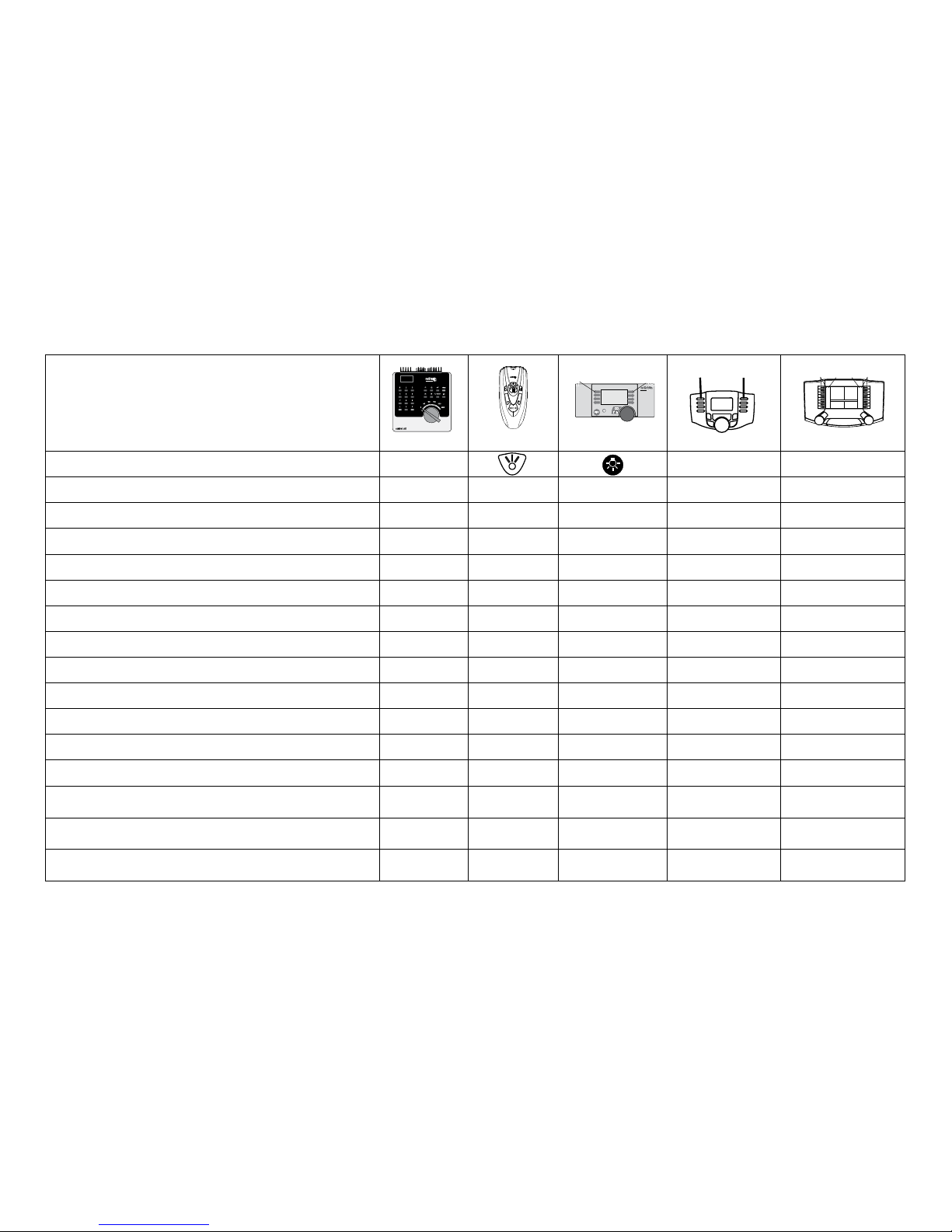
11
Fonctions commutables
Fanal function/off Fonction f0 Fonction f0
Générateur de fumée (Aux 1) f1 Fonction 1 Fonction * Fonction f1 Fonction f1
Bruitage : Bruit d’exploitation f2 Fonction 2 Fonction * Fonction f2 Fonction f2
Bruitage : sifflet f3 Fonction 3 Fonction * Fonction f3 Fonction f3
ABV désactivé f4 Fonction 4 Fonction * Fonction f4 Fonction f4
Fonctions physiques (Aux 3) —
1
— Fonction * Fonction f5 Fonction f5
Fonctions physiques (Aux 4) —
1
— Fonction * Fonction f6 Fonction f6
Bruitage : Cloche —
1
— Fonction * Fonction f7 Fonction f7
Attelage Telex (Aux 2) —
1
— Fonction * Fonction f8 Fonction f8
Bruitage : Grincement de freins désactivé —
1
— — Fonction f9 Fonction f9
Bruitage : Pelletage du charbon —
1
— — Fonction f10 Fonction f10
Bruitage : sifflet court —
1
— — Fonction f11 Fonction f11
Bruitage : Annonce en gare —
1
— — Fonction f12 Fonction f12
Bruitage : Grille à secousses —
1
— — Fonction f13 Fonction f13
Bruitage : Joints de rail —
1
— — Fonction f14 Fonction f14
Bruitage : Sifflet Contrôleur
—
1
— — Fonction f15 Fonction f15
f0 f8 f0f8
STOP
mobile station
systems
1
5
Digital/Systems
F0
F4
1
Commutable par l’intermédiaire des adresses de chaînage *Les icônes des fonctions peuvent être représentées de manière différente
Décodeur 60975
Page 60
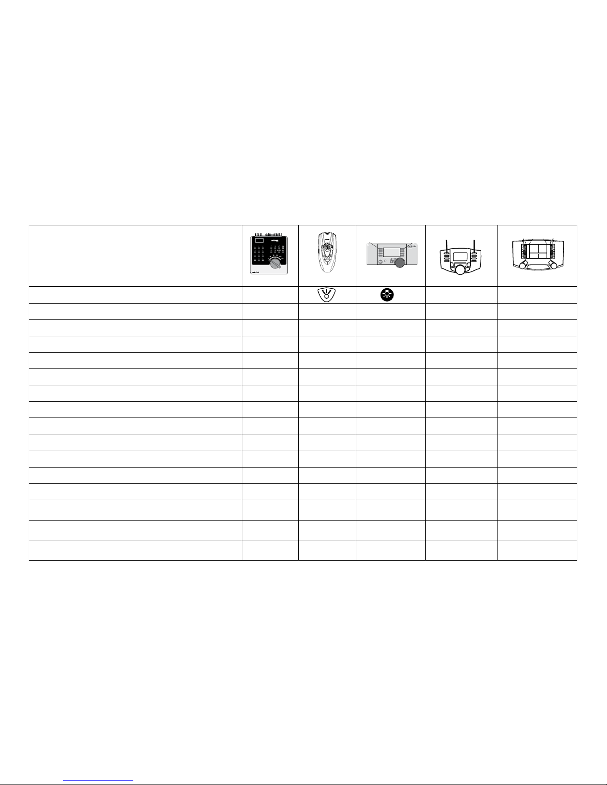
12
Fonctions commutables
Fanal function/off Fonction f0 Fonction f0
Eclairage de la cabine de conduite (Aux 1) f1 Fonction 1 Fonction * Fonction f1 Fonction f1
Bruitage : Bruit d’exploitation f2 Fonction 2 Fonction * Fonction f2 Fonction f2
Bruitage : Trompe 1 f3 Fonction 3 Fonction * Fonction f3 Fonction f3
ABV désactivé f4 Fonction 4 Fonction * Fonction f4 Fonction f4
Fonctions physiques (Aux 3)
—
1
— Fonction * Fonction f5 Fonction f5
Fonctions physiques (Aux 4)
—
1
— Fonction * Fonction f6 Fonction f6
Bruitage : Trompe 2 —
1
— Fonction * Fonction f7 Fonction f7
Attelage Telex (Aux 2) —
1
— Fonction * Fonction f8 Fonction f8
Bruitage : Grincement de freins désactivé —
1
— — Fonction f9 Fonction f9
Bruitage : Ventilateur —
1
— — Fonction f10 Fonction f10
Bruitage : Cloche —
1
— — Fonction f11 Fonction f11
Bruitage : Annonce en gare —
1
— — Fonction f12 Fonction f12
Bruitage : Diesel auxiliaire —
1
— — Fonction f13 Fonction f13
Bruitage : Joints de rail —
1
— — Fonction f14 Fonction f14
Bruitage : Sifflet Contrôleur —
1
— — Fonction f15 Fonction f15
f0 f8 f0f8
STOP
mobile station
systems
1
5
Digital/Systems
F0
F4
1
Commutable par l’intermédiaire des adresses de chaînage *Les icônes des fonctions peuvent être représentées de manière différente
Décodeur 60976
Page 61
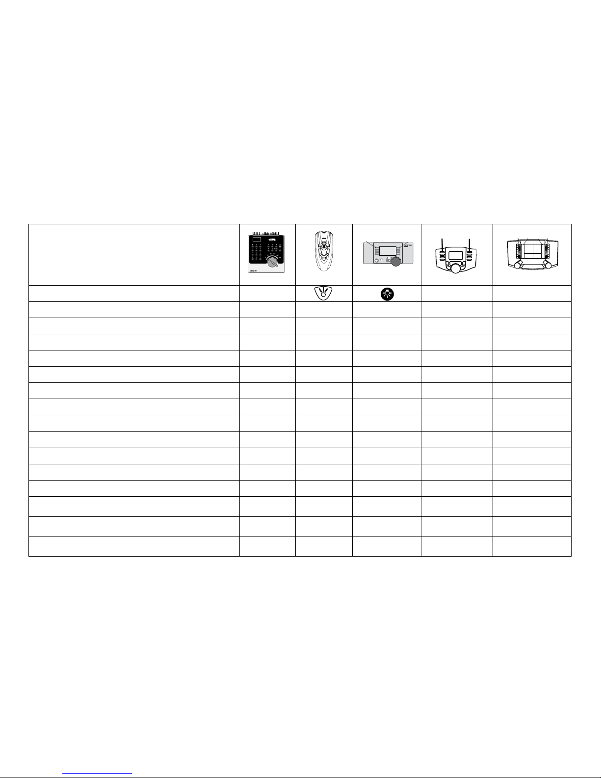
13
Fonctions commutables
Fanal function/off Fonction f0 Fonction f0
Eclairage de la cabine de conduite (Aux 1) f1 Fonction 1 Fonction * Fonction f1 Fonction f1
Bruitage : Bruit d’exploitation f2 Fonction 2 Fonction * Fonction f2 Fonction f2
Bruitage : Trompe 1 f3 Fonction 3 Fonction * Fonction f3 Fonction f3
ABV désactivé f4 Fonction 4 Fonction * Fonction f4 Fonction f4
Fonctions physiques (Aux 3)
—
1
— Fonction * Fonction f5 Fonction f5
Fonctions physiques (Aux 4)
—
1
— Fonction * Fonction f6 Fonction f6
Bruitage : Trompe 2 —
1
— Fonction * Fonction f7 Fonction f7
Attelage Telex (Aux 2) —
1
— Fonction * Fonction f8 Fonction f8
Bruitage : Grincement de freins désactivé —
1
— — Fonction f9 Fonction f9
Bruitage : Ventilateur —
1
— — Fonction f10 Fonction f10
Bruitage : sifflet —
1
— — Fonction f11 Fonction f11
Bruitage : Annonce en gare —
1
— — Fonction f12 Fonction f12
Bruitage : Compresseur —
1
— — Fonction f13 Fonction f13
Bruitage : Joints de rail —
1
— — Fonction f14 Fonction f14
Bruitage : Sifflet Contrôleur —
1
— — Fonction f15 Fonction f15
f0 f8 f0f8
STOP
mobile station
systems
1
5
Digital/Systems
F0
F4
1
Commutable par l’intermédiaire des adresses de chaînage *Les icônes des fonctions peuvent être représentées de manière différente
Décodeur 60977
Page 62

14
Modifier l’intensité sonore
Protocole mfx : dans le menu CV Son, la station centrale 60213/60214/60215 permet de modifier confortablement l’intensité sonore
globale des fonctions de bruit. Le mappage des fonctions (affectation des touches de fonction) et le paramétrage individuel de
l’intensité sonore s’opèrent par l’intermédiaire des touches de fonction. Pour le mappage des fonctions, il est nécessaire d’utiliser
le numéro du bruit.
Protocole fx : dans le cadre du protocole fx, seule l’intensité sonore globale peut être modifiée avec CV 63. Il est impossible de
procéder à une modification des différentes intensités sonores. Des paramétrages effectués sous mfx peuvent toutefois être
conservés.
Protocole DCC : Pour modifier le volume sonore vous devez d‘abord configurer CV 31 sur 16 et CV32 sur 0. Pour le mappage des
fonctions, il est nécessaire d’utiliser le numéro du bruit et l’affectation de la CV au bruit.
Fonctions sonores
Bruit-No.
Par défaut Valeurs
CV vapeur CV diesel CV électrique
Bruitage : Fonction f2 300
Son de
la marche
300
Son de
la marche
300
Son de
la marche
180 0 - 255
Bruitage : Fonction f3 301 1 301 1 301 1 180 0 - 255
Bruitage : Fonction f7 303 3 302 2 302 2 180 0 - 255
Bruitage : Fonction f10 309 9 309 9 309 9 180 0 - 255
Bruitage : Fonction f11 302 2 303 3 303 3 180 0 - 255
Bruitage : Fonction f12 304 4 304 4 304 4 180 0 - 255
Bruitage : Fonction f13 310 10 307 7 308 8 180 0 - 255
Bruitage : Fonction f14 314 14 314 14 314 14 180 0 - 255
Bruitage : Fonction f15 305 5 305 5 305 5 180 0 - 255
Volume total (CV63) et crissement des freins (CV 146) voir tableaux ci-dessous
Page 63

15
CV Signification Valeurs Par défaut Remarque
1 Adresse 1 (adresse principale)
1-255 (1
- 80)*
60975=78
60976=72
60977=24
L’adresse est toujours active n’est pas
dépendante de la CV 49.
2 Vitesse minimale (Vmin)
1-255 (1
- 80)*
4
Vitesse avec le cran de marche le plus
petit. La valeur doit être plus petite que
Vmax, CV 5.
3 Retard au démarrage (AV)
1-255 (1
- 80)*
12
Valeur CV multipliée par 0,25 donne le
temps de l’arrêt à la vitesse maximale.
4 Retard de freinage (BV)
1-255 (1
- 80)*
12
Valeur CV multipliée par 0,25 donne le
temps du retard au freinage.
5 Vitesse maximale (Vmax)
1-255
(1 - 63)*
{x4}*
180
Vitesse avec le cran de marche le plus
élevé. La valeur doit être plus grande
que CV2.
7 Période de lecture 77
Saisissez la valeur 77. La valeur 77 n‘est
pas enregistrée définitivement.
8
Réinitialisation décodeur (paramétrage par défaut ou
paramétrage usine)
8 - La valeur n’est pas saisie.
17 Adresse 3 (2ème adresse de chaînage)
1-255 (1
- 80)*
254
L’adresse peut être dés/activée, en
fonction de la CV 49.
18 Adresse 4 (3ème adresse de chaînage)
1-255 (1
- 80)*
253
L’adresse peut être dés/activée, en
fonction de la CV 49.
27
Mode de freinage :
Bit 0 – 3 : Toujours 0
Bit 4 : tension CC, polarité inverse au sens
de la marche
Bit 5 : tension CC, polarité dans le sens de
la marche
Bit 6 – 7 : Toujours 0
0
16
32
0
48
Freinage dépendant de la direction :
16 : fonctionnement DCC normal
32 : fonctionnement DCC inverse
Freinage indépendant de la direction :
48 : fonctionnement fx/mfx
Tableau des valeurs de configuration fx (MM)
* () = Control Unit 6021 {}* = Les valeurs saisies sont multipliée par x (facteur)
Page 64

16
CV Signification Valeurs Par défaut Remarque
29
Configuration :
Bit 0 : inverser le sens du fonctionnement de la
locomotive
0 = sens normal
1 = inverser le sens
Bit 1 : Nombre des crans de marche,
Demi crans 14 ou 27
0 = 14 crans de marches,
1 = 27 crans de marche/demi crans
Bit 2 : mettre en/hors fonction le mode
analogique
0 = analogique hors fonction,
1 = analogique en fonction
0 - 7 6
Le sens de fonctionnement se rapporte au
sens de la marche et à la lumière.
Le nombre des crans de marche et des
demi crans est fonction de l’engin de
traction.
Uniquement marche en mode numérique
ou aussi en mode conventionnel. Pendant
la marche, un changement à la volée est
possible.
49
Configuration étendue :
Bit 0 : Nombre d’adresses,
Bit 1 : Nombre d’adresses,
Bit 2 : Adressage de chaînage automatique
(en fonction / 1=hors fonction)
0 - 7 5
0 = une | 1 = deux | 0 = trois | 1 = quatre
0 = adr. | 0 adr. | 1 adr. | 1 adr.
0 = adr. de chaînage auto. en fonction /
1 = adr. de chaînage auto hors fonction
50
Formats alternatifs :
Bit 0 : analogique CA hors fonction = 0
analogique CA en fonction = 1
Bit 1 : analogique CC hors fonction = 0
Analogique C en fonction = 1
Bit 2 : DCC hors fonction /
DCC en fonction = 1
Bit 3 : mfx hors fonction = 0
Mfx en fonction = 1
0 - 15
0 / 1
0 / 2
0 / 4
0 / 8
15
Remarque :
Fx (MM) ne peut pas se désactiver
lui-même.
Tableau des valeurs de configuration fx (MM)
* () = Control Unit 6021 {}* = Les valeurs saisies sont multipliée par x (facteur)
Page 65

17
CV Signification Valeurs Par défaut Remarque
51
Bit 0 : Moteur inversé 1= marche, 0 arrêt
Bit 1 : Lumière inversée 1= marche, 0 arrêt
Bit 2 : Rail inversé 1= marche, 0 arrêt
Bit 3 : Aux 3 (1= sortie logique, 0= sortie renforcée)
Bit 4 : Aux 4 (1= sortie logique, 0= sortie amplifiée)
0 / 1
0 / 2
0 / 4
0 / 8
0 / 16
0
Vous devez additionner les valeurs
des paramètres requis.
52
Type de moteur …
…Aux – sorties fonctions 5 – 6
…Moteur – Softdrive Sinus
…Moteur – à tension variable
…Moteur – propulsion à haut rendement C90
…Moteur – induit en cloche
…Moteur – courant continu CC doux
…Moteur – courant continu CC dur
…Moteur – courant continu CC Spur 1
0 - 7
0
1
2
3
4
5
6
7
5
Choix d’un type de moteur pour un
réglage additionnel pour la régulation
moteur ou
Mode de fonctionnement des sorties
moteur en tant qu’Aux additionnels,
voir tableau supplémentaire
1
53 Régulation moteur – référence de régulation
1 - 255 (0 - 63)*
{x4}*
10
Vmax absolu pour courbe caractéristique moteur
54 Régulation moteur – paramètre de régulation K
1 - 255 (0 - 63)*
{x4}*
20 Partie de régulation K
55 Régulation moteur – paramètre de régulation I
1 - 255 (0 - 63)*
{x4}*
15 Partie de régulation I
56 Régulation moteur- influence de la régulation
1 - 255 (0 - 63)*
{x4}*
63
0 = PWM à tension variable pour Sinus
(voir aussi le type de moteur CV 52)
57
Locomotive à vapeur : intervalle entre sons produits
par les jets de vapeur pour le rapport de vitesse 1
1 - 255 (0 - 63)*
{x4}*
7 Sans capteur de vitesse de roue
Tableau des valeurs de configuration fx (MM)
* () = Control Unit 6021
{}* = Les valeurs saisies sont multipliée par x (facteur).
1
Vous trouverez sur internet un tableau détaillé sur le mappage des
fonctions à l’adresse : www.maerklin.de/de/produkte/tools_downloads/
technische_infos.html
Page 66

18
CV Signification Valeurs Par défaut Remarque
58
Locomotive à vapeur : intervalle entre sons produits
par les jets de vapeur à partir du rapport de vitesse 2
1 - 255 (0 - 63)*
{x4}*
22 Sans capteur de vitesse de roue
63 Intensité sonore au total
1 - 255 (0 - 63)*
{x4}*
63
Intensité sonore globale pour tous les
bruitages. 0 = aucun bruit
64 Seuil de grincement des freins
1 - 255 (0 - 63)*
{x4}*
9
Le grincement commence d’autant
plus tôt que la valeur est élevée,
d’autant plus tard que la valeur est
plus basse. Si la valeur est trop basse,
aucun grincement n’est enclenché.
73
Enregistrer différents états :
Bit 0 : enregistrer des états de fonctionnement
Bit 1 : Enregistrer la vitesse
Bit 2 : Après réinitialisation, démarrer avec/sans ABV
0 - 7
0 / 1
0 / 2
0 / 4
7
0 = ne pas enregistrer / 1 = enregistrer
0 = ne pas enregistrer / 2 = enregistrer
0 = sans ABV / 4 = avec ABV
74
Enregistrer différents états :
Bit 0 : enregistrer le sens de la marche
0 - 1 1 0 = ne pas enregistrer / 1 = enregistrer
75 Adresse 2 (1ère adresse de chaînage)
1 - 255
(1 - 80)*
60975=79
60976=73
60977=25
L’adresse peut être dés/activée, en
fonction de la CV 49.
76 Tension de démarrage en analogique DC
0-255 (1 - 63)
{x4}*
12
Indication pour la CS 1 : (140)
La CS 1 affiche la valeur invertie.
77 Vitesse maximale en analogique DC
0-255 (1 - 63)
{x4}*
43
78 Tension de démarrage en analogique AC
0-255 (1 - 63)
{x4}*
15
Remarque pour la CS1 : (140)
La CS 1 affiche la valeur invertie.
79 Vitesse maximale en analogique AC
0-255 (1 - 63)
{x4}*
49
Tableau des valeurs de configuration fx (MM)
* () = Control Unit 6021 {}* = Les valeurs saisies sont multipliée par x (facteur).
Page 67

19
CV Signification Valeurs Par défaut Remarque
1 Adresse principale 1 - 127 3
Adresse brève 1 – 127
Lorsque CV29 / bit 5 = 0
2
PoM
Vitesse minimale (Vmin) 0 - 255 4
La valeur doit être inférieure à Vmax, CV 5.
(voir CV 67).
3
PoM
Retard au démarrage (AV) 0 - 255 12
Valeur CV multipliée par 0,9 donne le temps, de
l’arrêt jusqu’à la vitesse maximale.
4
PoM
Retard au freinage (BV) 0 - 255 12
Valeur CV multipliée par 0,9 donne le temps, de
la vitesse maximale jusqu’à l’arrêt.
5
PoM
Vitesse maximale (Vmax) 0 - 255 180
Vitesse pour le cran de marche le plus élevé.
La valeur doit être supérieure à Vmin, CV 2.
(voir aussi la CV 94).
7
Période de lecture
Numéro de version du fabricant (version du
logiciel)
77 –
Saisissez la valeur 77. La valeur 77 n‘est pas
enregistrée définitivement.
8
Identification / identité du fabricant
Réinitialisation du décodeur (paramétrage par
défaut ou paramétrage usine)
–
8
131
–
Lire uniquement
La valeur ne peut pas être lue
13
PoM
Fonctions F1 – F8 pour un signal de voie alternatif 0 - 255
60975=1
60976=0
60976=0
0 = # fonction hors fonction,
1 = # fonction en fonction
Bit 7-0 [F8 F7 F6 F5 F4 F3 F2 F1]
14
PoM
Fonctions FL, F9 – F15 pour un signal de voie
alternatif
0 - 255 1
Signal de voie alternatif = MM, analogique
0 = fonction / hors fonction,
1 = fonction / en fonction
[F15 F14 F13 F12 F11 F10 F9 FL]
17 Adresse étendue, octet de poids fort 192 - 231 192
Adresse longue 1 – 10239 (128)
Lorsque la CV29 / bit 5 = 1
18 Adresse étendue, octet de poids faible 0 - 255 128
19 Adresse de la traction 0 - 255 0
1 – 127 = Adresse de la traction
0 = pas de traction
+128, bit 7 = inverser la polarité du sens de la
marche au niveau de la traction.
Tableau des valeurs de configuration DCC
La PoM doit être supportée par le contrôleur
Page 68

20
CV Signification Valeurs Par défaut Remarque
21
PoM
Fonctions F1 – F8 pour la traction 0 - 255 0
0 = # de fonction uniquement pour adresse
locomotive
1 = # de fonction aussi pour l’adresse de la
traction
Bit 7 – 0 = [F8 F7 F6 F5 F4 F3 F2 F1]
22
PoM
Fonctions FL, F9 – F 15 pour la traction 0 - 255 0
0 = # de fonction uniquement pour adresse
locomotive
1 = # de fonction aussi pour l’adresse de la
traction
Bit 7 – 0 = [F8 F7 F6 F5 F4 F3 F2 F1]
27
PoM
Mode de freinage :
Bit 0 – 3 : toujours 0
Bit 4 : tension CC, polarité inverse du sens de
la marche
Bit 5 : tension CC, polarité dans le sens de la
marche
Bit 6 – 7 : toujours 0
0 - 48
0
0 / 16
0 / 32
0
48
Freinage en fonction du sens de la marche
- 16 : fonctionnement CC normale
- 32 : fonctionnement CC inverse
Freinage en fonction du sens de la marche
- 48 : fonctionnement fx / mfx
29
PoM
Configuration :
Bit 0 : inverser le sens de fonctionnement de la
locomotive
0 = sens normal,
1 = inverser le sens
Bit 1 : choisir les crans de marche 14 ou 28/128
0 = 14 crans de marche,
1 = 28/128 crans de marche
Bit 2 : mode analogique hors / en fonction
0 = analogique hors fonction,
1 = analogique en fonction
Bit 5 : choisir une adresse brève / longue
0 = adresse brève,
1 = adresse longue
0 - 39
0
1
0
2
0
4
0
32
6
Le sens de fonctionnement se rapporte au
sens de la marche et à la lumière. Le nombre
de crans de marche et le bit de lumière sont
fonction de l’engin de traction.
En guise d’adresse de locomotive, soit
l’adresse principale brève, soi l’adresse
étendue longue.
Tableau des valeurs de configuration DCC
La PoM doit être supportée par le contrôleur
Page 69

21
Tableau des valeurs de configuration DCC
CV Signification Valeurs Par défaut Remarque
31
PoM
Index high Byte 16 16
Requis pour les paramètres avancés, par ex.
CV 300 - 328
32
PoM
Index low Byte 0 0
50
PoM
Formats alternatifs :
Bit 0 : Analogique CA hors fonction = 0 / analogique CA en fonction = 1
Bit 1 : Analogique CC hors fonction = 0 / analogique CC en fonction = 1
Bit 2 : fx (MM) hors fonction = 0 / fx (MM) en
fonction = 1
Bit 3 : mfx hors fonction = 0 / mfx en fonction = 1
0 - 15
0 / 1
0 / 2
0 / 4
0 / 8
15
Indication :
DCC ne peut pas se désactiver lui-même.
51
PoM
Bit 0 : Moteur inversé 1= marche, 0 arrêt
Bit 1 : Lumière inversée 1= marche, 0 arrêt
Bit 2 : Rail inversé 1= marche, 0 arrêt
Bit 3 : Aux 3 (1= sortie logique, 0= sortie renforcée)
Bit 4 : Aux 4 (1= sortie logique, 0= sortie renforcée)
0 / 1
0 / 2
0 / 4
0 / 8
0 / 16
0
Vous devez additionner les valeurs des
paramètres requis.
52
PoM
Type de moteur … (bit 0 – 4)
…Aux – sorties fonctions 5 – 6
…Moteur – Softdrive Sinus
…Moteur – à tension variable
…Moteur – propulsion à haut rendement C90
…Moteur – induit en cloche
…Moteur – courant continu CC doux
…Moteur – courant continu CC dur
…Moteur – courant continu CC Spur 1
0 - 7
0
1
2
3
4
5
6
5
Choix d’un type de moteur pour un réglage
additionnel pour la régulation moteur ou
Choix de sorties fonction additionnelles au
niveau d’un décodeur HO.
Mode de fonctionnement des sorties moteur
en tant qu’Aux additionnels, voir tableau
supplémentaire1
53
PoM
Régulation moteur – référence de régulation 0 - 255 40
Vmax absolu pour courbe caractéristique
moteur
54
PoM
Régulation moteur – paramètre de régulation K 0 - 255 80 Partie de régulation K
La PoM doit être supportée par le contrôleur
Page 70

22
CV Signification Valeurs Par défaut Remarque
55
PoM
Régulation moteur – paramètre de régulation I 0 - 255 60 Partie de régulation I
56
PoM
Régulation moteur- influence de la régulation 0 - 255 255
0 = PWM à tension variable pour Sinus (voir
aussi le type de moteur CV 52)
57
PoM
Locomotive à vapeur : intervalle entre sons produits
par les jets de vapeur pour le rapport de vitesse 1
0 - 255 30 Sans capteur de vitesse de roue
58
PoM
Locomotive à vapeur : intervalle entre sons produits
par les jets de vapeur à partir du rapport de vitesse 2
0 - 255 90 Sans capteur de vitesse de roue
63
PoM
Intensité sonore au total 0 - 255 255
Intensité sonore globale pour tous les bruitages. 0 = aucun bruit
64
PoM
Seuil de grincement des freins 0 - 255 35
Le grincement commence d’autant plus tôt
que la valeur est élevée, d’autant plus tard que
la valeur est plus basse. Si la valeur est trop
basse, aucun grincement n’est enclenché.
66
PoM
Limitation de la vitesse avant (« Forward trim ») 0 - 255 128
La valeur de la CV divisée par 128 donne le
facteur avec lequel le cran de marche est
multiplié dans le cas d’une marche avant.
67
PoM
-
94
PoM
Tableau des vitesses, cran de marche 1 (Vmin)
jusqu’à
Tableau des vitesses, crans de marche 28 (Vmax)
0 - 255
95
PoM
Limitation de la vitesse arrière (« Reverse trim ») 0 - 255 128
Valeur CV divisée par 128 donne le facteur
avec lequel le cran de marche est multiplié
lors d’une marche arrière.
145
PoM
Rapport de manoeuvre 0 - 128 128
1128 = 50 % du cran de marche, 64 = 25 % du
cran de marche
146
PoM
Sortie son : grincement des freins (intensité sonore)
0
180
Tableau des valeurs de configuration DCC
La PoM doit être supportée par le contrôleur
0 - 255
Page 71
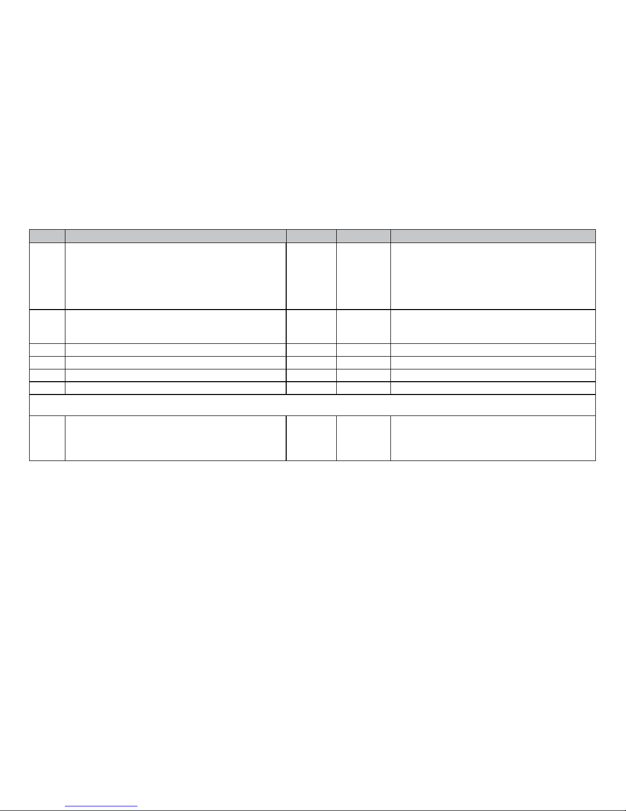
23
Tableau des valeurs de configuration DCC
CV Signification Valeurs Par défaut Remarque
173
PoM
Enregistrer différents états :
Bit 0 : Enregistrer des états fonctionnels
Bit 1 : Enregistrer la vitesse
Bit 2 : Après réinitialisation, démarrer avec/
sans ABV
Bit 3 - 7 : toujours 0
0 / 1
0 / 2
0 / 3
7
0 = ne pas enregistrer, valeur = enregistrer,
certaines valeurs doivent être additionnées
174
PoM
Enregistrer différents états :
Bit 0 : enregistrer le sens de la marche
Bit 1 - 7 : toujours 0
0 / 1 1
0 = ne pas enregistrer
1 = enregistrer
176
PoM
Vmin analogique DC 0 - 255 50 Doit être plus petit que CV 177
177
PoM
Vmax analogique DC 0 - 255 170 Doit être plus grand que CV 176
178
PoM
Vmin analogique AC 0 - 255 60 Doit être plus petit que CV 179
179
PoM
Vmax analogique AC 0 - 255 190 Doit être plus grand que CV 178
Pour modifier le volume sonore (CV 300 - CV 328) vous devez d‘abord configurer CV 31 sur 16/ CV32 sur 0 (cf. CV31)
300
PoM
301
PoM
-
328
PoM
Sortie son : intensité sonore du bruit de circulation *
Sortie son : intensité sonore son 1
*
à
Sortie son : intensité sonore son 16 *
0 - 255
0 - 255
0 - 255
180
180
180
0 = pas de son
La PoM doit être supportée par le contrôleur
* Vous trouverez sur internet un tableau détaillé sur le mappage des fonctions à l’adresse :
www.maerklin.de/de/produkte/tools_downloads/technische_infos.html
Page 72

24
Eliminer la perturbation
En cas d’exploitation avec différents protocoles, des perturbations réciproques peuvent se produire. – Il est recommandé de réduire le nombre des protocoles. Désactiver les
protocoles non nécessaires dans le décodeur de locomotive
et au besoin aussi dans la centrale.
La locomotive donne des saccades et s’arrête – contrôler
le paramétrage des CVs pour la variante moteur, le cas
échéant, le modifier ou procéder à une réinitialisation des
paramètres usine.
La locomotive ne marche pas en mode analogique –
l’identification analogique automatique est désactivée et
doit être réactivée (voir le tableau CV).
La locomotive (décodeur) ne réagit pas – examiner le
câblage et la brasure, le cas échéant les retoucher. Vérier
la fermeté des contacts et l’orientation de la pose des
interfaces du décodeur.
Fonctionnement en mode mfx/DCC : des locomotives à
l’arrêt sur le circuit démarre immédiatement au moment
de recevoir le signal mfx. Pour ces locomotives, désactiver
l’identification analogique automatique.
La locomotive ne démarre pas – la fonction ouvrir les portes
/ fermer les portes est encore active. Terminer l’exécution
de fonction Fermer les portières. Après la fin du son, la
locomotive démarre conformément au dispositif antiblocage
(ABV) paramétré.
Elimination
Indications relatives à la protection de
l’environnement : Les produits marqués du
signe représentant une poubelle barrée ne
peuvent être éliminés en fin de vie via les
ordures ménagères normales, mais doivent
être remis à un centre de collecte pour
le recyclage des appareils électriques et
électroniques. Le symbole figurant sur le produit lui-même,
la notice d’utilisation ou l’emballage l’indique. Les matériaux
sont recyclables selon leur marquage. Avec le recyclage, la
récupération des matériaux ou autres formes de valorisation de vieux appareils, vous contribuez sensiblement à la
protection de notre environnement. Renseignez-vous auprès
de votre municipalité sur les centres compétents pour le
traitement des déchets.
Garantie
Garantie légale et garantie contractuelle conformément au
certificat de garantie ci-joint.
• Pour toute réparation ou remplacement de pièces,
adresses-vous à votre détaillant-spécialiste Märklin.
Gebr. Märklin & Cie. GmbH
Reparaturservice
Stuttgarter Str. 55 - 57
73033 Göppingen
Germany
Tel: +49 7161 608 222
E-Mail: [email protected]
Page 73

25
Page 74

26
Verantwoord gebruiken
De decoders 60945/60946/60947 zijn bedoelt voor het ombouwen van Märklin/Trix H0-locomotieven.
!
Niet geschikt voor motoren met een veldspoel. Locomotieven met deze motoren moeten met de daarvoor bestemde
motor-ombouwsets 60941, 60943 of 60944 omgebouwd
worden.
Leveringsomvang:
1 decoder
1 print met 21-polige stekker (NEM)
1 plaat
1 schroef
1 Luidspreker, klein
1 Luidspreker , groot
1 zelfklevende pad
Inbouwaanwijzin
Garantiebewijs
Voor het inbouwen heeft men daarnaast de volgende ge-
reedschappen nodig: schroevendraaier, pincet en soldeerstation met een soldeertemperatuur van max. 30W/300º C
en een dunne stift, elektronica soldeertin (Ø 0,5-1mm)
desoldeerlitze of tinzuiger.
Veiligheidsvoorschriften
• Let op! Bevat functionele scherpe kanten.
• Bedrading- en montagewerkzaamheden alleen in span-
ningsloze toestand uitvoeren. Indien deze aanwijzing niet
opgevolgd wordt, kan dit gevaarlijke lichaamsstromen en
verwondingen tot gevolg hebben.
• De decoder alleen met de toegelaten spanning (zie
technische gegevens) gebruiken.
Bij het werken met een soldeerbout bestaat het gevaar
voor brandwonden.
Technische gegevens
• Continu belasting van de motoruitgang ≤ 1.1 amps
• Belasting van de lichtuitgangen ≤ 250 milliamps
• Belasting AUX 1 – AUX 4 elk ≤ 250 milliamps
• Belasting AUX 3 - 4 (logische uitgang) —
• Belasting AUX + licht (gezamenlijk) v 300 milliamps
• Belasting motor resp. AUX 5/6 ≤ 1.1 amps
• Maximale totaal belasting (gezamenlijk) ≤ 1.6 amps
• Maximale spanning ≤ 40 volts
• Belasting geluid (aan 4 Ω / 8 Ω) 2,75 W / 1,6 W
• Kortsluit- en overbelastingbeveiliging op de uitgangen
licht voor (LV), licht achter (LH), AUX1 – AUX4 en op de
motoruitgangen.
Functies
De mSD SoundDecoder is een sounddecoder met zeer veel
instel- en aanpassingsmogelijkheden. Extra geluidsfuncties zijn beschikbaar. De decoder kan worden geüpdatet.
Hiervoor is een geschikt besturingsapparaat (Central
Station 60213/60214/60215, software versie 4.0 of hoger en
railformaat-processor 60971).
De instel- en digitale functies zijn alleen in digitaalbedrijf
beschikbaar. Dezelfde mogelijkheden zijn echter niet binnen
elk protocol beschikbaar.
Deze gebruiksaanwijzing beschrijft het inbouwen en de
Page 75

27
instelmogelijkheden van de decoder 60975/60976 en 60977.
Voor zover niet anders aangegeven hebben de functies
betrekking op beide decoders.
• Multiprotocol (fx(MM), mfx, DCC en AC/DC)
• Automatische systeem herkenning. Voor het bedienen
dient het in het desbetreffende systeem toegewezen
adres gebruikt te worden.
• De optrek- en afremvertraging kunnen apart van elkaar
ingesteld worden. Via de functiemapping kan elke
gewenste functietoets toegewezen worden.
• Typische geluiden voor diesel- en elektrische locomotieven.
• Variabele motorregeling in digitaal- en ook in analoogbedrijf.
• Ondersteuning voor 6090, 60901, DC- en klokanker-
motoren.Bij Sinus-motoren moet CV 52 op 1 en CV 56 op
0 ingesteld worden. (zie CV tabel) CV 51 op 24 danwel op
0 instellen. Daarnaast dient u Aux 3 en Aux 4 elk op stil-
stand (S) en rijden (F) te mappen met het Central Station
of de programmer 60971.
• Functiemapping, zie hiervoor het helpbestand in het
Central Station 60213/60214/60215 of de uitgebreide tabel
voor functiemapping in het internet onder:
www.maerklin.de/de/produkte/tools_downloads/technische_infos.html
• Kan geüpdatet worden met het Central Station
60213/60214/60215 (software versie 4.0 of hoger of met de
programmer 60791)
• Programming on Main (PoM), deze programmeerwijze
moet door het bedieningsapparaat ondersteund worden.
Lees hiervoor de aanwijzingen in de gebruiksaanwijzing
van uw bedieningsapparaat.
• Instelbare rangeerstand
• Afrem- / stopsectie herkenning in digitaalbedrijf.
•
Automatisch inmeten van de locomotief met CV7 (mfx, DCC,
MM).
Decoder inbouwen
Voor het inbouwen van de decoder dient men eerst de
elektrische- en mechanische werking van de locomotief te
controleren en zo nodig te herstellen.
Soldeer eerst de draden aan de stroomafnemer (sleepcontact), motor en verlichting los. Daarna verwijdert u de
oude decoder of rijrichtingschakelaar. Bevestigingsplaat
vastschroeven, draden volgens schema op de motor, sleper
en eventuele functies aansluiten.
Draadkleuren overeenkomstig de Märklin-standaard.
Vergelijkingstabel naar NEM zie (pag. 28).
Als de verlichting direct met de massa van het voertuig
is verbonden, is het aan te bevelen deze van de massa te
isoleren. Gebruik daarvoor de steekfitting E604180 en het
gloeilampje E610080. Hiermee voorkomt u het flikkeren van
de verlichting.
Is het voertuig voorzien van LED verlichting, dan dient er
een voorschakelweerstand ingebouwd te worden. Deze
weerstanden zijn er in verschillende waarden en vormen.
Gebruik de juiste waarde voor u LED. Vraag dit eventueel
uw dealer.
Indien u het voertuig nadien van LED verlichting wilt voorzien, dan moet de kathode (-) van de LED met de lichtuitgang
verbonden worden. Vergeet de voorschakelweerstand
Page 76
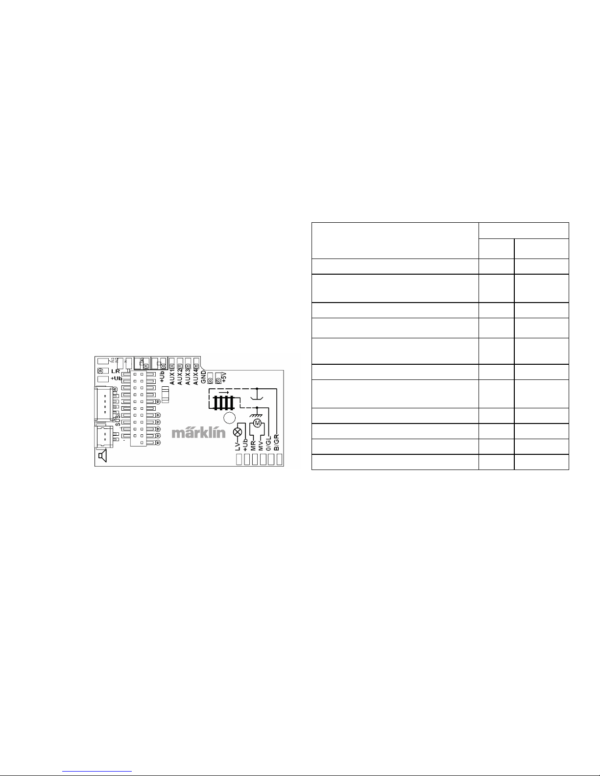
28
niet! De anode (+) wordt dan met de gemeenschappelijke
retourdraad (oranje) verbonden.
De gemeenschappelijke retourdraad (oranje) mag niet met
de massa van het voertuig verbonden worden. Plaats de
luidsprekers, met de meegeleverde zelfklevende pad fxieren
en steek de kabel in de connector van de printplaat.
Vergelijkingstabel voor de draadkleuren
Omschrijving
Draadkleur
NEM Märklin
Motoruitgang 2 grijs blauw
2-rail stroomopname linker railstaaf
3-rail stroomopname railstaven
zwart bruin
Verlichting voor wit grijs
Aux 1 (fysieke uitgang) groen bruin/rood
Gemeenschappelijke retour voor
verlichting/Aux 1 - 4
blauw oranje
Verlichting achter geel geel
2-rail stroomopname rechter railstaaf
3-rail stroomopname middenrail
rood rood
Motoruitgang 1 oranje vert
Aux 2 (fysieke uitgang) paars bruin/groen
Aux 3 (fysieke uitgang) bruin/geel
Aux 4 (fysieke uitgang) bruin/wit
geel
orange
grijs
oranje
blauw
groen
bruin
rood
orange
orange
bruin/rood
bruin/groen
bruin/geel
bruin/wit
Luidspreker
Page 77
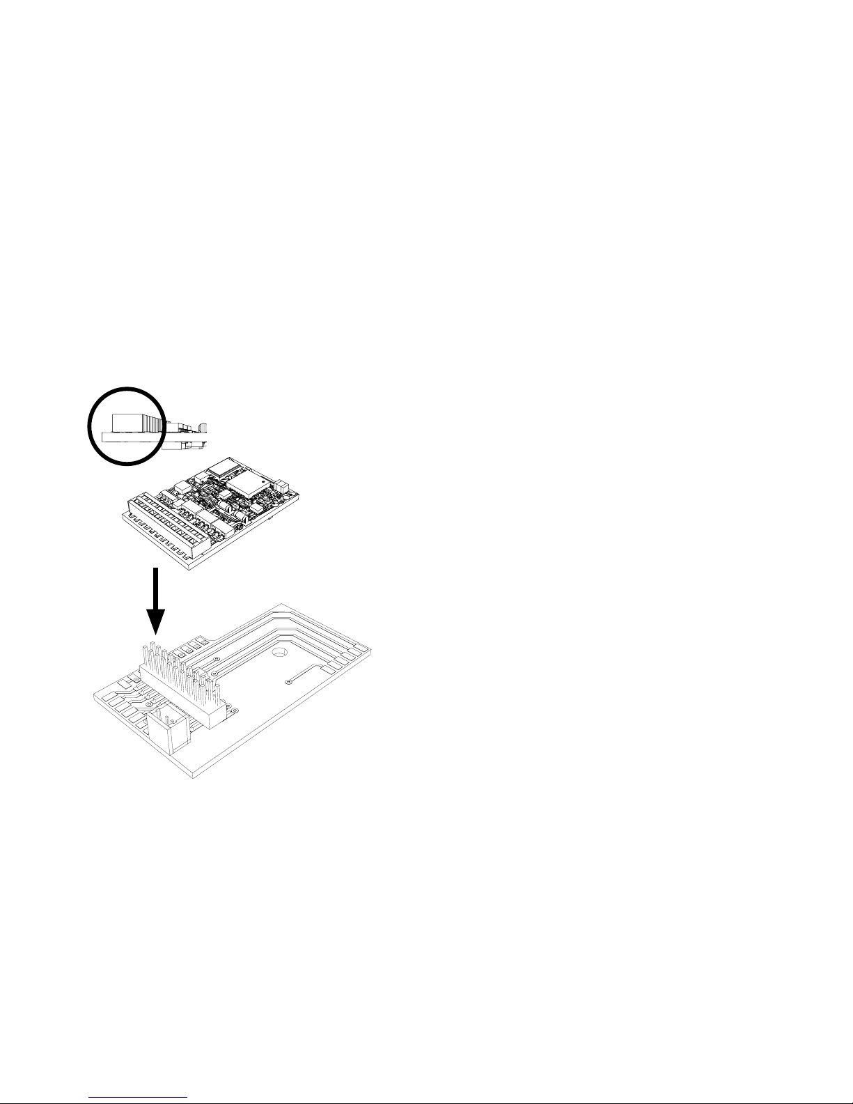
29
De decoder op de stekker steken, let op de juiste inbouw.
Model zonder de kap op het programmeerspoor plaatsen
voor het testen. Als de decoder goed functioneert kan de
kap weer op de loc geplaatst worden.
!
Multiprotocolbedrijf
Analoogbedrijf
De decoder kan ook op analoge modelbanen of spoortrajecten gebruikt worden. De decoder herkent de analoge
wissel- of gelijkspanning (AC/DC) automatisch en past zich
aan de analoge railspanning aan. Alle functies die onder
mfx of DCC voor het analoge bedrijf zijn ingesteld, worden
geactiveerd (zie digitaalbedrijf).
Digitaalbedrijf
De mSD SoundDecoder is een multiprotocoldecoder. De
decoder kan onder de volgende digitale protocollen ingezet
worden: mfx, DCC, fx (MM).
Het digitaalprotocol met de meeste mogelijkheden is het
primaire digitaalprotocol. De volgorde van de digitaalprotocollen is afnemend in mogelijkheden:
Prioriteit 1: mfx
Prioriteit 2: DCC
Prioriteit 3: fx (MM)
Opmerking: de digitale protocollen kunnen elkaar beïnvloe-
den. Voor een storingsvrij bedrijf is het aan te bevelen de
niet gebruikte protocollen met CV 50 te deactiveren. Deactiveer eveneens, voor zover uw centrale dit ondersteunt, ook
de daar niet gebruikte digitale protocollen.
Worden twee of meer digitaal protocollen op de rails
herkend, dan neemt de decoder automatisch het protocol
met de hoogste prioriteit, bijv. mfx/DCC, dan wordt door de
decoder het mfx-digitaalprotocol gebruikt (zie bovenstaand
overzicht).
Page 78

30
Opmerking: let er op dat niet alle functies in alle digitaalprotocollen mogelijk zijn. Onder mfx of DCC kunnen enkele
instellingen, welke in analoogbedrijf werkzaam moeten zijn,
ingesteld worden.
Afrem-/stopsectie fx (MM), mfx, DCC
De afremmodules zetten in principe een gelijkspanning op
de rails. Herkent de decoder een dergelijke gelijkspanning
op de rails, dan remt de loc met de ingestelde vertraging
af. Herkent de decoder wederom een digitaalprotocol, dan
trekt de loc weer op tot de ingestelde snelheid.
Als het automatisch herkennen van de afremsectie gebruikt
dient te worden, is het aan te bevelen het DC-bedrijf uit te
schakelen (zie CV beschrijving).
Automatisch inmeten voor alle protocollen
• Voor het inmeten dient eerst het motortype gekozen te
worden (zie CV 52).
• Het automatisch inmeten van de locomotief dient op een
daarvoor geschikt ovaal zonder hindernissen (seinen,
stijgingen e.d.) te geschieden. Aanbevolen is een ovaal
met een radius groter dan 430 mm. De locomotief trekt
namelijk op tot de maximumsnelheid en kan dan, bij een
te kleine radius, uit de bocht vliegen. Voor het automatisch inmeten van de loc gaat u in de locconfiguratie van
het Central Station -> CV -> info. In het veld firmware
overschrijft u het eerst cijfer met 77. In de protocollen
MM/DCC voert u via de configuratiemodus direct CV7
in. Overschrijf de daar getoonde waarden met 77 en sla
dat op in de loc. Stel met de rijregelaar een snelheid in.
Nu trekt de loc langzaam op tot de maximumsnelheid
en stopt na korte tijd. Daarna maakt de loc meerdere
optrekproeven. Blijft de loc langere tijd stilstaan, dan is
het inmeten beëindigt.
Tijdens het gehele verloop mag niet worden ingegrepen.
Met de toets “STOP”, het draaien aan de rijregelaar of
het wisselen van de rijrichting kan het inmeten afgebroken worden. Na een onderbreking moet de gehele
afloop weer herhaald worden. Stelt het inmeten niet
tot tevredenheid, dan kan het inmeten met een ander
motortype herhaald worden. Het is mogelijk dit meerdere
keren te herhalen.
Heeft de inmeetrit niet tot het gewenste resultaat
geleidt, dan kunnen in de motorparameter handmatig de
verschillende parameters gewijzigd worden. (MM/DCC
zie CV-tabel, mfx in de locconfiguratie van het Central
Station -> CV -> motor).
Door de volgende lichtsignalen wordt het begin en het
einde van de inmeetrit weergegeven.
Uitvoerige informatie hierover in het Internet: www.
maerklin.de/de/produkte/tools_downloads/technische_informationen.html
Geactiveerd (Waarde 77 invoeren)
Start van de meetrit
(rijstap > 1)
Einde van de meetrit
Afgebroken of storing
Page 79

31
mfx-protocol
Adressering
• Een adres is niet nodig, elke decoder heeft een éénmalig
en éénduidig kenmerk (UID).
• De decoder meldt zich vanzelf aan bij het Central Station
of Mobile Station met zijn UID.
Programmering
• De eigenschappen kunnen m.b.v. het grasche scherm
op het Central Station resp. deels ook met het Mobile
Station geprogrammeerd worden.
• Alle conguratie variabelen (CV) kunnen vaker gelezen
en geprogrammeerd worden.
• De programmering kan zowel op het hoofdspoor als op
het programmeerspoor gebeuren.
• De default-instellingen (fabrieksinstelling) kunnen weer
hersteld worden.
• Functiemapping: functies kunnen met behulp van het
Central Station 60212 (met beperking) en met het Central
Station 60213/60214/60215 aan elke gewenste functietoets
worden toegewezen (zie het helpbestand in het Central
Station.
Verdere informatie vindt u op het Internet: www.maerklin.de/
de/produkte/tools_downloads/technische_informationen.
html.
fx-protocol (MM)
Adressering
• 4 adressen (één hoofdadres en drie volgadressen).
• Adresbereik:
1-225 afhankelijk van het besturingsapparaat/centrale
• Hoofdadres is handmatig programmeerbaar
• De volgadressen zijn in- uitschakel- en instelbaar en zijn
handmatig of automatisch programmeerbaar.
• Via deze vier adressen zijn alle zestien functies te schakelen.
Programmeren
• De eigenschappen van de decoder kunnen via de
programmering van de configuratie variabelen (CV) vaker
geprogrammeerd worden. Het lezen van de CV is niet
mogelijk.
• Het CV-nummer en de CV-waarde worden direct ingevoerd.
• Programmering van de CV alleen op het programmeerspoor.
• De default-instellingen (fabrieksinstelling) kunnen weer
hersteld worden.
• 14 resp. 27 rijstappen instelbaar.
• De eerste vier functies en het licht zijn via het hoofdadres
altijd te schakelen, verdere functies zijn afhankelijk van
het vervolgadres beschikbaar.
• Alle instellingen uit de functiemapping van de mfx- of
DCC programmering worden overgenomen voor fx (MM).
• Automatische herkenning overeenkomstig de actieve
extra- of volgadressen. Herkend wordt, of de functie
continu in- resp. uitgeschakeld of via een volgadres
schakelbaar is. Deze functiemapping kan alleen via het
mfx- of DCC-protocol vastgelegd worden.
• Voor verdere informatie, zie de CV-tabel fx-protocol.
Page 80

32
DCC-protocol
Adressering
• Kort adress - lang adres - tractie adres
• Adresbereik:
1 – 127 kort adres, tractie adres
1 – 10239 lang adres
• Elk adres is handmatig programmeerbaar.
• Kort of lang adres wordt via de CV gekozen.
• Een toegepast tractieadres deactiveert het standaarda-
dres.
Programmering
• De eigenschappen van de decoder kunnen via de conguratie variabelen (CV) vaker gewijzigd worden.
• De CV-nummers en de CV-waarden worden direct ingevoerd.
• De CV’s kunnen vaker gelezen en geprogrammeerd
worden (programmering op het programmeerspoor).
• De CV’s kunnen naar wens geprogrammeerd worden
(programmering op het hoofdspoor PoM). PoM is alleen
bij de in de CV-tabel aangegeven CV’s mogelijk. De
programmering op het hoofdspoor (PoM) moet door uw
centrale ondersteund worden (zie de gebruiksaanwijzing
van uw apparaat).
• De default-instellingen (fabrieksinstelling) kunnen weer
hersteld worden.
• 14/28 resp. 126 rijstappen instelbaar.
• Voor het automatisch afremmen is het aanbevolen in
DCC bedrijf de waarde in CV 27 op 16 of 32 (zie pag. 43) in
te stellen.
Fysieke functies
Elke fysieke functie moet extern op de print aangesloten
worden. Men spreekt daarom van fysieke functies. Aan elke
fysieke uitgang (AUX / licht) kan in het digitale bedrijf een
eigen modus / effect toegewezen worden. Hiervoor zijn voor
elke uitgang 4 CV‘s beschikbaar. Er kan voor elke uitgang
slechts één modus / effect ingesteld worden. Een uitvoerige
tabel hiervoor vindt u op het internet onder:
www.maerklin.de/de/produkte/tools_downloads/technische_infos.html
Logische functies
Aangezien deze functies uitsluitend via de software uitgevoerd worden, is hier geen fysieke uitgang voor nodig. Daarom
spreekt men hier dan ook van een logische functie.
Optrek- en afremvertraging
• De optrek- en afremvertraging kan gescheiden van
elkaar ingesteld worden.
• De logische functie uitschakeling (ABV = optrek-en
afremvertraging) kan d.m.v. functiemapping aan elke
gewenste functietoets worden toegewezen.
• Alle functies kunnen overeenkomstig de functiemapping
geschakeld worden (zie CV-beschrijving).
• Verdere informatie, zie CV-tabel DCC-protocol en op het
Internet ( adres zie fysieke functies).
Voor verdere informatie, zie de CV-tabel DCC-protocol.
Het is aan te bevelen om het programmeren alleen op het
programmeerspoor uit te voeren.
Page 81

33
Rangeerstand
• De rangeerstand zorgt voor het reduceren van de actuele
snelheid. Dit maakt het zeer precies regelen van de
locomotief mogelijk. De rangeerstand kan bij mfx of DCC
d.m.v. functiemapping aan elke gewenste functietoets
worden toegewezen (zie CV 145 p. 45).
Stationsomroep
De loc gaat pas rijden nadat het oproepbericht is beëindigd.
Deuren openen / deuren sluiten
Zolang de functie deuren openen / deuren sluiten actief is,
gaat de loc niet rijden. Pas als de functie gedeactiveerd en
het geluid afgelopen is begint de loc, overeenkomstig de
ingestelde ABV, op te trekken.
Decoder functies en CV instellingen
Verderop vindt u de functies en de CV’s in tabelvorm
weergegeven. Via deze CV’s heeft u de mogelijkheid om
een verscheidenheid aan instellingen en de toewijzing van
functietoetsen te wijzigen.
U vindt de CV’s en de gebruiksmogelijkheden voor de railformaten fx (MM) en DCC in gescheiden tabellen.
Het railformaat mfx kunt u comfortabel via het display van
het CS 2, vanaf softwareversie 2.0, instellen. Indien nodig
moet u of uw handelaar een update van uw Central Station
60213/60214/60215 uitvoeren.
Page 82
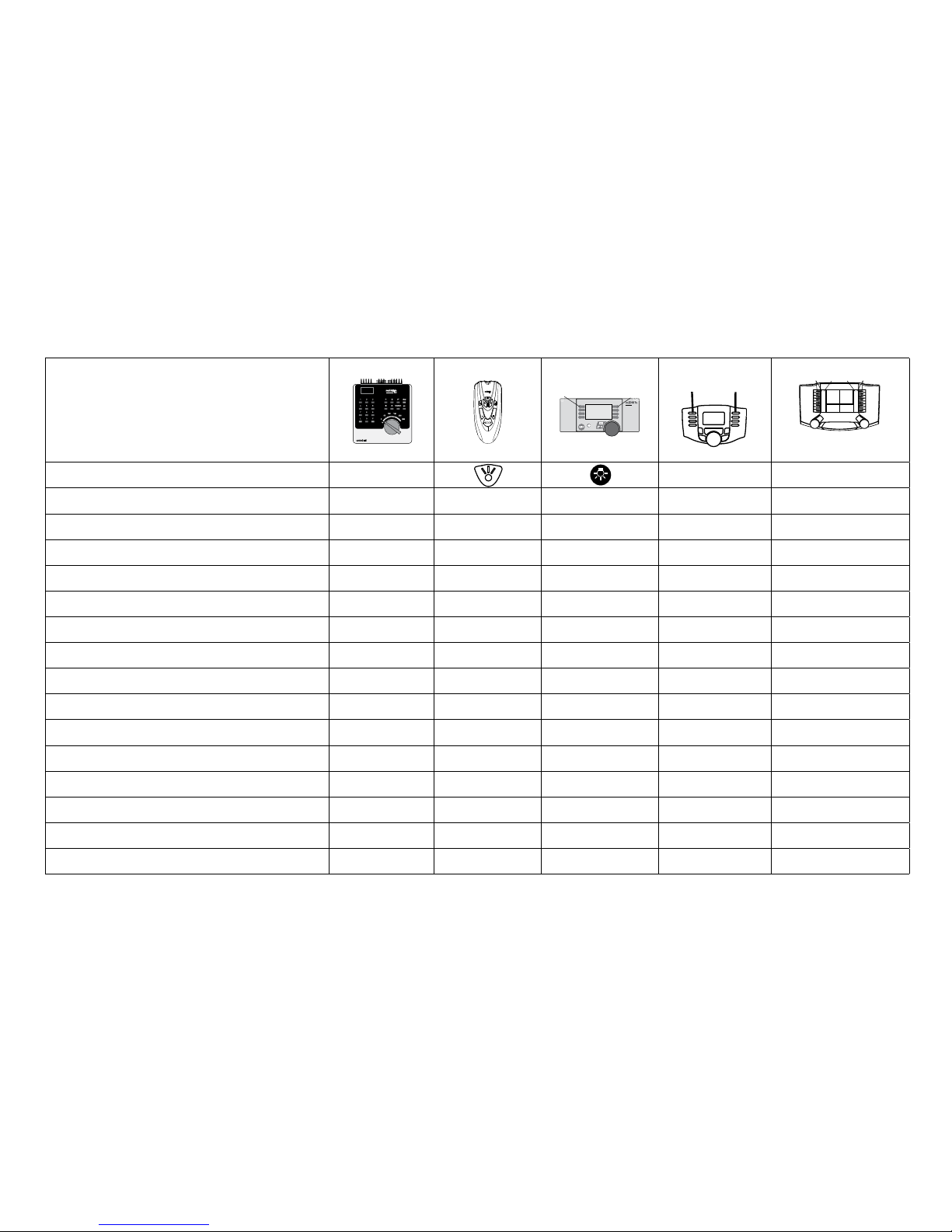
34
Schakelbare functies
Frontverlichting function/off Functie f0 Functie f0
Rookgenerator (Aux 1) f1 Functie 1 Functie * Functie f1 Functie f1
Geluid: bedrijfsgeluiden f2 Functie 2 Functie * Functie f2 Functie f2
Geluid: fluit f3 Functie 3 Functie * Functie f3 Functie f3
ABV uit f4 Functie 4 Functie * Functie f4 Functie f4
Fysieke functie (Aux 3) —
1
—
Functie *
Functie f5 Functie f5
Fysieke functie (Aux 4) —
1
— Functie * Functie f6 Functie f6
Geluid: luidklok —
1
— Functie * Functie f7 Functie f7
Telex-koppeling (Aux 2) —
1
— Functie * Functie f8 Functie f8
Geluid: piepende remmen uit —
1
— — Functie f9 Functie f9
Geluid: kolenscheppen —
1
— — Functie f10 Functie f10
Geluid: fluit kort —
1
— — Functie f11 Functie f11
Geluid: stationsomroep —
1
— — Functie f12 Functie f12
Geluid: schudrooster
—
1
— — Functie f13 Functie f13
Geluid: raillassen —
1
— — Functie f14 Functie f14
Geluid: conducteurfluit —
1
— — Functie f15 Functie f15
f0 f8 f0f8
STOP
mobile station
systems
1
5
Digital/Systems
F0
F4
* Functiesymbolen kunnen afwijkend
1
Via vervolgadressen schakelbaar
Decoder 60975
Page 83
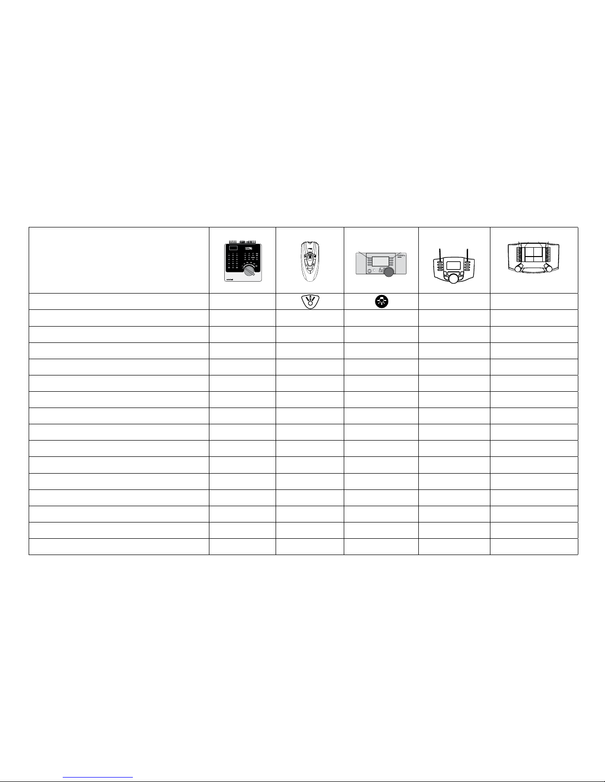
35
Schakelbare functies
Frontverlichting function/off Functie f0 Functie f0
Cabineverlichting (Aux 1) f1 Functie 1 Functie * Functie f1 Functie f1
Geluid: bedrijfsgeluiden f2 Functie 2 Functie * Functie f2 Functie f2
Geluid: signaalhoorn 1 f3 Functie 3 Functie * Functie f3 Functie f3
ABV uit f4 Functie 4 Functie * Functie f4 Functie f4
Fysieke functie (Aux 3) —
1
—
Functie *
Functie f5 Functie f5
Fysieke functie (Aux 4) —
1
— Functie * Functie f6 Functie f6
Geluid: signaalhoorn 2 —
1
— Functie * Functie f7 Functie f7
Telex-koppeling (Aux 2) —
1
— Functie * Functie f8 Functie f8
Geluid: piepende remmen uit —
1
— — Functie f9 Functie f9
Geluid: ventilator —
1
— — Functie f10 Functie f10
Geluid: luidklok —
1
— — Functie f11 Functie f11
Geluid: stationsomroep —
1
— — Functie f12 Functie f12
Geluid: hulpdiesel
—
1
— — Functie f13 Functie f13
Geluid: raillassen —
1
— — Functie f14 Functie f14
Geluid: conducteurfluit —
1
— — Functie f15 Functie f15
f0 f8 f0f8
STOP
mobile station
systems
1
5
Digital/Systems
F0
F4
* Functiesymbolen kunnen afwijkend
1
Via vervolgadressen schakelbaar
Decoder 60976
Page 84
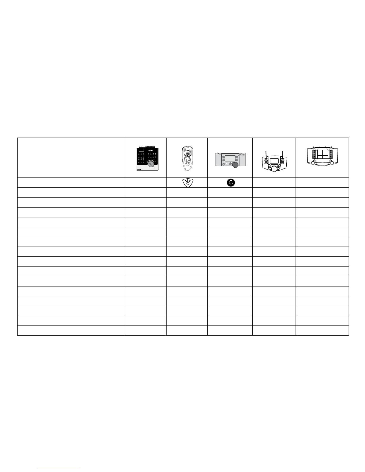
36
Schakelbare functies
Frontverlichting function/off Functie f0 Functie f0
Cabineverlichting (Aux 1) f1 Functie 1 Functie * Functie f1 Functie f1
Geluid: bedrijfsgeluiden f2 Functie 2 Functie * Functie f2 Functie f2
Geluid: signaalhoorn 1 f3 Functie 3 Functie * Functie f3 Functie f3
ABV uit f4 Functie 4 Functie * Functie f4 Functie f4
Fysieke functie (Aux 3) —
1
—
Functie *
Functie f5 Functie f5
Fysieke functie (Aux 4) —
1
— Functie * Functie f6 Functie f6
Geluid: signaalhoorn 2 —
1
— Functie * Functie f7 Functie f7
Telex-koppeling (Aux 2) —
1
— Functie * Functie f8 Functie f8
Geluid: piepende remmen uit —
1
— — Functie f9 Functie f9
Geluid: ventilator —
1
— — Functie f10 Functie f10
Geluid: fluit —
1
— — Functie f11 Functie f11
Geluid: stationsomroep —
1
— — Functie f12 Functie f12
Geluid: compressor
—
1
— — Functie f13 Functie f13
Geluid: raillassen —
1
— — Functie f14 Functie f14
Geluid: conducteurfluit —
1
— — Functie f15 Functie f15
f0 f8 f0f8
STOP
mobile station
systems
1
5
Digital/Systems
F0
F4
* Functiesymbolen kunnen afwijkend
1
Via vervolgadressen schakelbaar
Decoder 60977
Page 85

37
Volume veranderen
mfx-protocol: het algemene volume van de geluidfuncties is met het Central Station 60213/60214/60215 comfortabel, in het
menu sound, te wijzigen. De functiemapping (toewijzen van de functietoetsen) en de individuele volume instelling gebeurd
via de functietoetsen. Het soundnummer is nodig voor de functiemapping.
fx-protocol: in het fx-protocol kan alleen het algemen volume met CV63 veranderd worden. Het veranderen van de afzonderlijke geluiden is niet mogelijk. Echter, de in mfx gewijzigde instellingen blijven behouden.
DCC-protocol: Voor het veranderen van het volume moet CV 31 eerst op de waarde 16 en CV 32 op de waarde 0 gezet worden . De soundnummers zijn nodig bij de functiemapping en bij de toewijzing van de CV aan de sound.
Sound-functies
Sound-Nr.
Default Waarde
CV Stoom CV Diesel CV Elektrisch
Geluid: Functie f2 300 Rijgeluid 300 Rijgeluid 300 Rijgeluid 180 0 - 255
Geluid: Functie f3 301 1 301 1 301 1 180 0 - 255
Geluid: Functie f7 303 3 302 2 302 2 180 0 - 255
Geluid: Functie f10 309 9 309 9 309 9 180 0 - 255
Geluid: Functie f11 302 2 303 3 303 3 180 0 - 255
Geluid: Functie f12 304 4 304 4 304 4 180 0 - 255
Geluid: Functie f13 310 10 307 7 308 8 180 0 - 255
Geluid: Functie f14 314 14 314 14 314 14 180 0 - 255
Geluid: Functie f15 305 5 305 5 305 5 180 0 - 255
Totale volume (CV63) en remmen piepen (CV 146) zie tabellen hieronder
Page 86

38
CV Omschrijving Waarde Default Opmerking
1 Adres 1 (hoofdadres) 1-255 (1 - 80)*
60977=78
60976=72
60975=24
Adres is altijd actief en is niet afhankelijk van
CV 49.
2 Minimumsnelheid (Vmin) 1-255 (1 - 80)* 4
CV-waarde vermenigvuldigd met 0,25 geeft de
tijd van stilstand tot de maximumsnelheid.
3 Optrekvertraging (AV) 1-255 (1 - 80)* 12
CV value multiplied by 0.25 gives the time from
complete stop to maximum speed.
4 Afremvertraging (BV) 1-255 (1 - 80)* 12
CV-waarde vermenigvuldigd met 0,25 geeft de
tijd van het afremmen
5 Maximumsnelheid (Vmax)
1-255 (1 - 63)*
{x4}*
180
Snelheid bij de hoogste rijstap. Waarde moet
groter zijn dan Vmin, CV 2.
7 Inmeetrit 77
Waarde 77 invoeren. Waarde 77 wordt niet
blijvend opgeslagen.
8
Decoder resetten
(default- of fabrieksinstelling)
8 Waarde wordt niet geschreven.
17 Adres 3 (2de vervolgadres) 1-255 (1 - 80)* 254
Adres kan de/activeert worden in afhankelijkheid van CV 49.
18 Adres 4 (3de vervolgadres 1-255 (1 - 80)* 253
Adres kan de/activeert worden in afhankelijkheid van CV 49.
27
Afremmodus:
Bit 0 - 3 : altijd 0
Bit 4 : Polariteit tegen de rijrichting in
Bit 5 : DC , Polariteit overeenkomstig de
rijrichting
Bit 6 - 7: altijd afremmen (fx/mfx)
0 - 48
0
16
32
0
48
Rijrichting afhankelijk afremmen:
- 16 normaal DCC gedrag
- 32 omgekeerd DCC gedrag
Afremmen onafhankelijk van de rijrichting:
- 48 : fx/mfx - gedrag
CV-tabel fx (MM)
* () = 6021 Control Unit {}* = de ingevoerde waarden worden met X (factor) vermenigvuldigd.
Page 87

39
CV Omschrijving Waarde Default Opmerking
29
Configuratie:
Bit 0 : Rijrichtinggedrag van de loc omkeren
0 = Richting normaal,
1 = Richting omkeren
Bit 1 : aantal rijstappen,
tussenstappen 14 of 27
0 = 14 Rijstappen,
1 = 27 Rijstappen / tussenstappen
Bit 2 : Analoogbedrijf uit-/inschakelen·
0 = Analoog uit, 1 = Analoog aan
0 - 7 6
Het rijrichtinggedrag heeft betrekking op de
rijrichting en het licht.
Het aantal rijstappen en de tussenstappen
zijn afhankelijk van de rijregelaar.
Alleen in digitaal bedrijf of ook in conventioneel bedrijf. Tijdens het bedrijf is een
vliegende wissel mogelijk.
49
Uitgebreide configuratie:
Bit 0 : aantal adressen, LSB
Bit 1 : aantal adressen, MSB
Bit 2 : automatische vervolgadressering
(in 0 / 1=uit)
0 - 7 5
0 = een | 1 = twee | 0 = drie | 1 = vier
0 Adr. | 0 Adr. | 1 Adr. | 1 Adr.
0 = auto. vervolg / 1 = auto. vervolg uit
50
Alternatieve formaten:
Bit 0 : Analoog AC uit = 0 / Analoog AC aan = 1
Bit 1 : Analoog DC uit = 0 / Analoog DC aan = 1
Bit 2 : DCC uit = 0 / DCC aan = 1
Bit 3 : mfx uit = 0 / mfx aan = 1
0 - 15
0 / 1
0 / 2
0 / 4
0 / 8
15
Opmerking:
fx (MM) kan zich zelf niet deactiveren.
51
Bit 0: motor geïnviteerd 1=aan, 0 uit
Bit 1: licht geïnviteerd 1=aan, 0 uit
Bit 2: rail geïnviteerd 1=aan, 0 uit
Bit 3: Aux 3 (1= logisch, 0= versterkte uitgang
Bit 4: Aux 4 (1= logisch, 0= versterkte uitgang
0 / 1
0 / 2
0 / 4
0 / 8
0 / 16
0
De waarden van de benodigde instellingen
moet bij elkaar opgeteld worden.
CV-tabel fx (MM)
* () = 6021 Control Unit {}* = de ingevoerde waarden worden met X (factor) vermenigvuldigd.
Page 88

40
CV Omschrijving Waarde Default Opmerking
52
Motortype ...
... Aux – functie-uitgang 5 en 6
... Motor - Softdrive Sinus
... Motor - ongeregeld
... Motor – hoogvermogen-aandrijving C90
... Motor - klokanker
... Motor - gelijkstroom DC zacht
... Motor - gelijkstroom DC hard
... Motor - gelijkstroom DC Spoor 1
0 - 7
0
1
2
3
4
5
6
7
5
Kies een motortype voor verdere
instelling van de motorregeling.
of
kies extra functie-uitgangen bij
een H0-Decoder. Werkwijze van de
motoruitgang als extra Aux uitgangen,
zie tabel 1.
53 Motorregeling – regelreferentie
1 - 255 (0 - 63)*
{x4}*
10 Absolute Vmax voor motorkromme
54 Motorregeling – regelparameter K
1 - 255 (0 - 63)*
{x4}*
20 Regelaandeel P
55 Motorregeling – regelparameter I
1 - 255 (0 - 63)*
{x4}*
15 Regelaandeel I
56 Motorregeling - regelinvloed
1 - 255 (0 - 63)*
{x4}*
63
0 = ongeregelde PWM voor Sinus
(zie ook CV 52 motortype)
57
Stoomloc geluidsafstand van de stoomstoten bij rijstap 1
1 - 255 7 zonder wielas sensor
58
Stoomloc geluidsafstand van de stoomstoten bij rijstap 2
1 - 255 22 zonder wielas sensor
63 Volume algemeen 1 - 255 63
Algemeen volume voor alle geluiden.
0 = geen geluiden
CV-tabel fx (MM)
* () = 6021 Control Unit {}* = de ingevoerde waarden worden met X (factor) vermenigvuldigd.
1
Een uitvoerige tabel hiervoor vindt u op het internet onder: www.maerklin.de/de/produkte/tools_downloads/technische_infos.html
Page 89

41
CV Omschrijving Waarde Default Opmerking
64 Piepende remgeluiden
1 - 255 (0 - 63)*
{x4}*
9
Het remgeluid begint, hoe groter de
waarde, des te vroeger en hoe kleiner
de waarde des te later. Is de waarde
te klein, dan wordt het piepen van de
remmen niet weergegeven.
73
Verschillende toestanden opslaan:
Bit 0 : functie toestanden opslaan
Bit 1 : snelheid opslaan
Bit 2 : na een reset met/zonder ABV wegrijden
0 - 7
0 / 1
0 / 2
0 / 4
7
0 = niet opslaan / 1 = opslaan
0 = niet opslaan / 2 = opslaan
0 = zonder ABV / 4 = met ABV
74
Verschillende toestanden opslaan:
Bit 0 : rijrichting opslaan
0 - 1 1 0 = niet opslaan / 1 = opslaan
75 Adres 2 (1ste vervolgadres)
1 - 255
(1 - 80)*
60975=79
60976=73
60977=25
Adres kan de/activeert worden,
Afhankelijk van CV 49.
76 Analoog DC startspanning
0-255 (1 - 63)*
{x4}*
12
Opmerking voor het CS1: (140)
Het CS1 geeft de waarde geïnverteerd
weer.
77 Analoog DC maximumsnelheid
0-255 (1 - 63)*
{x4}*
43
78 Analoog AC startspanning
0-255 (1 - 63)*
{x4}*
15
Opmerking voor het CS1: (140)
Het CS1 geeft de waarde geïnverteerd
weer.
79 Analoog AC maximumsnelheid
0-255 (1 - 63)*
{x4}*
49
CV-tabel fx (MM)
* () = 6021 Control Unit {}* = de ingevoerde waarden worden met X (factor) vermenigvuldigd.
Page 90

42
CV Omschrijving Waarde
Default
Opmerking
1 Hoofdadres 1 - 127 3 Kort adres 1 – 127 als CV29 / Bit 5 = 0
2
PoM
Minimumsnelheid (Vmin) 0 - 255 4
Waarde moet kleiner zijn dan Vmax, CV
5. (zie CV 67)
3
PoM
Optrekvertraging (AV) 0 - 255 12
CV-waarde vermenigvuldigd met 0,9 geeft
de tijd van stilstand tot de maximumsnelheid.
4
PoM
Afremvertraging (BV) 0 - 255 12
CV-waarde vermenigvuldigd met 0,9 geeft
de tijd van maximumsnelheid tot stilstand.
5
PoM
Maximumsnelheid (Vmax) 0 - 255 180
Snelheid bij de hoogste rijstap. Waarde
moet groter zijn dan Vmin, CV 2 (zie ook
CV 94).
7
Inmeetrit
Versienummer van fabrikant (Softwareversie)
77
Waarde 77 invoeren. Waarde 77 wordt
niet blijvend opgeslagen.
8
Fabrikantkenmerk / ID
Decoder resetten (default- of fabrieksinstelling)
–
8
131
–
Alleen lezen
Waarde kan niet gelezen worden.
13
PoM
Functies F1 - F8 bij alternatief railsignaal 0 - 255
60975=1
60976=0
60977=0
alternatief railsignaal = MM, analoog
0 = funct. # uit, 1 = funct. # aan
Bit 7 - 0 [ F8 F7 F6 F5 F4 F3 F2 F1 ]
14
PoM
Functies FL, F9 – F15 bij alternatief railsignaal 0 - 255 1
alternatief railsignaal = MM, analoog
0 = funct. # uit, 1 = funct. # aan
Bit 7 - 0 [ F15 F14 F13 F12 F11 F10 F9 FL ]
17 Uitgebreid adres, hoge byte 192 - 231 192
Lang adres 1 - 10239 (128)
als CV29 / bit 5 = 1
18 Uitgebreid adres, lage byte 0 - 255 128
CV-tabel DCC
PoM dient door het besturingsapparaat ondersteund te worden.
Page 91

43
CV Omschrijving Waarde
Default
Opmerking
19 Tractieadres 0 - 255 0
1 - 127 = Tractieadres 0 = geen tractie
+128, bit 7 = richting ompolen bij tractie
21
PoM
Functies F1 - F8 bij tractie 0 - 255 0
0 = funct. # alleen voor locadres
1 = funct. # ook voor tractieadres
Bit 7-0 = [ F8 F7 F6 F5 F4 F3 F2 F1 ]
22
PoM
Functies FL, F9 - F15 bij tractie 0 - 255 0
0 = funct. # alleen voor locadres
1 = funct. # ook voor tractieadres
Bit 7-0 = [ F15 F14 F13 F12 F11 F10 F9 FL ]
27
PoM
Afremmodus:
Bit 0 - 3: altijd 0,
Bit 4 : DC polariteit tegen de rijrichting in
Bit 5 : DC polariteit met de rijrichting mee
Bit 6 - 7: altijd 0
0 - 48
0
0 / 16
0 / 32
0
48
Remmen rijrichtingafhankelijk:
- 16: normaal DC gedrag
- 32: omgekeerd DC gedrag
Remmen rijrichtingonafhankelijk:
- 48 : gedrag fx/mfx
29
PoM
Configuratie:
Bit 0: Rijrichting van de loc omkeren
0 = richting normaal
1 = richting omgekeerd
Bit 1: rijstappen 14 of 28/128 kiezen
0 = 14 rijstappen
1 = 28/128 rijstappen
Bit 2: analoogbedrijf uit-/inschakelen
0 = analoog uit
1 = analoog aan
Bit 5: kort/ lang adres kiezen
0 = kort adres
1 = lang adres
0 - 39
0
1
0
2
0
4
0
32
6
Het rijrichtinggedrag heeft betrekking op
de rijrichting en het licht.
Het aantal rijstappen en het licht bit zijn
afhankelijk van de rijregelaar.
Als locadres dan wel het korte hoofdadres of het lange uitgebreide adres.
CV-tabel DCC
PoM dient door het besturingsapparaat ondersteund te worden.
Page 92

44
CV-tabel DCC
CV Omschrijving Waarde
Default
Opmerking
31
PoM
Index hoge byte 16 16
Is nodig voor verdere instellingen bijv. CV
300 - 328
32
PoM
Index lage byte 0 0
50
PoM
Alternatief formaat:
Bit 0: analoog AC uit = 0 / analoog AC aan = 1
Bit 1: Analoog DC uit = 0 / analoog DC aan = 1
Bit 2: fx (MM) uit = 0 / fx (MM) aan = 1
Bit 3: mfx uit = 0 / mfx aan = 1
0 - 15
0 / 1
0 / 2
0 / 4
0 / 8
15
Opmerking:
DCC kan zichzelf niet deactiveren.
51
PoM
Bit 0: motor geïnviteerd 1=aan, 0 uit
Bit 1: licht geïnviteerd 1=aan, 0 uit
Bit 2: rail geïnviteerd 1=aan, 0 uit
Bit 3: Aux 3 (1= logisch, 0= versterkte uitgang
Bit 4: Aux 4 (1= logisch, 0= versterkte uitgang
0 / 1
0 / 2
0 / 4
0 / 8
0 / 16
0
De waarden van de benodigde instellingen moet bij elkaar opgeteld worden.
52
PoM
Motortype ... (bit 0-4)
... Aux – functie-uitgang 5 en 6
... Motor - Softdrive Sinus
... Motor - ongeregeld
... Motor - hoogvermogen-aandrijving C90
... Motor - klokanker
... Motor - gelijkstroom DC zacht
... Motor - gelijkstroom DC hard
... Motor - gelijkstroom DC Spoor 1
0 - 7
0
1
2
3
4
5
6
7
5
Kies een motortype voor verdere instelling van de motorregeling.
of
kies extra functie-uitgangen bij een H0Decoder. Werkwijze van de motoruitgang
als extra Aux uitgangen, zie extra tabel
53
PoM
Motorregeling - regelreferentie 0 - 255 40 Absolute Vmax voor motorkromme.
54
PoM
Motorregeling - regelparameter K 0 - 255 80 Regelaandeel P
55
PoM
Motorregeling - regelparameter I 0 - 255 60 Regelaandeel I
56
PoM
Motorregeling - regelinvloed 0 - 255 255
0 = ongeregelde PWM voor Sinus
(zie ook CV 52 motortype)
PoM dient door het besturingsapparaat ondersteund te worden.
Page 93

45
CV Omschrijving Waarde
Default
Opmerking
57
PoM
Stoomloc geluidsafstand van de stoomstoten bij rijstap
1
0 - 255 30
58
PoM
Stoomloc geluidsafstand van de stoomstoten bij rijstap
2
0 - 255 90
63
PoM
Volume algemeen 0 - 255 255
Algemeen volume voor alle geluiden.
0 = geen geluiden
64
PoM
Piepende remgeluiden 0 - 255 35
Het remgeluid begint, hoe groter de
waarde, des te vroeger en hoe kleiner de
waarde des te later. Is de waarde te klein,
dan wordt het piepen van de remmen niet
weergegeven.
66
PoM
Vooruit trimmen 0 - 255 128
De CV-waarde gedeeld door 128 geeft
de factor waarmee de rijstap bij het
vooruitrijden vermenigvuldigd wordt.
67
PoM
-
94
PoM
Snelheidstabel rijstap 1 (Vmin)
tot
Snelheidstabel rijstap 28 (Vmax)
0 - 255
95
PoM
Achteruit trimmen 0 - 255 128
De CV-waarde gedeeld door 128 geeft de
factor waarmee de rijstap bij het achteruitrijden vermenigvuldigd wordt.
145
PoM
Rangeerstand 0 - 128 128 128 = 50% rijstap 64 = 25% rijstap
146
PoM
Sound uitgang: piepende remmen (volume) 0 - 255 180
CV-tabel DCC
PoM dient door het besturingsapparaat ondersteund te worden.
Page 94
46
CV-tabel DCC
CV Omschrijving Waarde
Default
Opmerking
173
PoM
Verschillende toestanden opslaan:
Bit 0 : functie toestanden opslaan
Bit 1 : snelheid opslaan
Bit 2 : na een reset met/zonder ABV wegrijden
Bit 3 - 7 : altijd 0
0 / 1
0 / 2
0 / 4
7
0 = niet opslaan, waarde = opslaan, de
verschillende waarden moeten opgeteld
worden.
174
PoM
Verschillende toestanden opslaan:
Bit 0 : rijrichting opslaan
Bit 1 - 7 : altijd 0
0 / 1 1
0 = niet opslaan
1 = opslaan
176
PoM
Vmin analoog DC 0 - 255 50 moet kleiner zijn dan CV 177
177
PoM
Vmax analoog DC 0 - 255 170 moet groter zijn dan CV 176
178
PoM
Vmin analoog AC 0 - 255 60 moet kleiner zijn dan CV 179
179
PoM
Vmax analoog AC 0 - 255 190 moet groter zijn dan CV 178
Voor het veranderen van het volume (CV 300 - CV 328) moet CV 31 eerst op de waarde 16/CV 32 op de waarde 0 gezet worden ( zie CV 31).
300
PoM
301
PoM
328
PoM
Sound uitgang: volume rijgeluid *
Sound uitgang: volume sound 1 *
naar
Sound uitgang: volume sound 16 *
0 - 255
0 - 255
0 - 255
180
180
180
0 = geen Sound
PoM dient door het besturingsapparaat
ondersteund te worden.
* Een uitvoerige tabel hiervoor vindt u op het internet onder:
www.maerklin.de/de/produkte/tools_downloads/technische_infos.html
Page 95

47
Storingen verhelpen
Bij het bedrijf met verschillende protocollen kan er onderlinge verstoring ontstaan. Het is aan te bevelen, het aantal
protocollen te reduceren. De niet benodigde protocollen in
de locdecoder en eventueel ook in de centrale deactiveren.
Loc schokt en hapert – CV instellingen van de motorvarianten controleren en eventueel deze wijzigen of terugzetten op
de fabrieksinstelling.
Loc rijdt analoog niet – de automatische analoog herkenning
is gedeactiveerd en dient weer geactiveerd te worden (zie
de CV-tabel).
Loc (decoder) reageert niet – bedrading en solderingen
controleren en eventueel herstellen. Contacten van de
stekkerverbinding en de inbouwrichting van de decoder
controleren.
mfx/DCC bedrijf: de op de modelbaan staande locomotieven
rijden direct na de mfx aanmelding weg. Bij deze locomotieven de automatische analoog herkenning deactiveren.
Loc rijdt niet – de functie deuren openen / deuren sluiten
is nog actief. De functie deuren sluiten beëindigen, na het
beëindigen van het geluid rijdt de loc weg met de ingestelde
optrekvertraging.
Afdanken
Aanwijzing voor de bescherming van het milieu:
Producten die voorzien zijn van een merkteken
met een doorgekruiste afvalcontainer, mogen
aan het eind van hun levensduur niet met het
normale huisafval afgevoerd worden. Deze
moeten op een inzamelpunt voor het recyclen
van elektrische- en elektronische apparaten
ingeleverd worden. Het symbool op het product, de verpakking of de gebruiksaanwijzing wijst daarop. De grondstoffen
zijn vanwege hun kwaliteiten opnieuw te gebruiken. Met het
hergebruik, recyclen van grondstoffen of andere vormen
voor het benutten van oude apparaten levert u een belangrijke bijdrage aan de bescherming van ons milieu. Vraag
bij uw gemeente naar de daarvoor bestemde inzamelplaats.
Garantie
Vrijwaring en garantie overeenkomstig het bijgevoegde
garantiebewijs.
Neem voor reparaties contact op met uw Märklin dealer of
stuur het op aan het Märklin service centrum.
Gebr. Märklin & Cie. GmbH
Reparaturservice
Stuttgarter Str. 55 - 57
73033 Göppingen
Germany
Tel: +49 7161 608 222
E-Mail: [email protected]
Page 96

Gebr. Märklin & Cie. GmbH
Stuttgarter Str. 55 - 57
73033 Göppingen
Germany
www.maerklin.com
260058/0516/Sc2Ef
Änderungen vorbehalten
© Gebr. Märklin & Cie. GmbH
Due to different legal requirements regarding electro-magnetic compatibility, this item
may be used in the USA only after separate certification for FCC compliance and an
adjustment if necessary.
Use in the USA without this certification is not permitted and absolves us of any liability. If you should want such certification to be done, please contact us – also due to the
additional costs incurred for this.
www.maerklin.com/en/imprint.html
Page 97
Set de decoder retroequipable para loco. de vapor 60975
Set de decoder retroequipable para loco. diésel 60976
Set de decoder retroequipable para loco. eléctrica 60977
Corredo di trasformazione Decoder loco vapore 60975
Corredo di trasformazione Decoder loco diesel 60976
Corredo di trasformazione Decoder loco elettrica 60977
Page 98

2
Índice de contenido Página
Uso correcto 3
Alcance de suministro 3
Instrucciones de seguridad 3
Datos técnicos 3
Funciones 3
Montaje del decoder 4
Funcionamiento multiprotocolo 6
- Tramo de frenado/parada en señal
ferroviaria fx (MM), mfx, DCC 7
- Calibración automática de los protocolos 7
- Protocolo mfx 7
- Protocolo fx (MM) 8
- Protocolo DCC 8
Funciones físicas 9
Funciones lógicas 9
Funciones del decodificador y la configuración de CV
10
Funciones conmutables 11
Variación del volumen 14
La tabla CV fx (MM) 15
La tabla CV DCC 19
Solución de anomalías 24
Eliminación 24
Garantía 24
Indice del contenuto Page
Impiego commisurato alla destinazione 25
Corredo di fornitura 25
Avvertenze per la sicurezza 25
Dati Tecnici 26
Funzioni 26
Installazione del Decoder 27
Esercizio multi-protocollo 28
- Sezione di frenatura/arresto al
segnale fx (MM), mfx, DCC 30
- Calibrazione automatica per tutti i protocolli 30
- Protocollo mfx 30
- Protocollo fx 31
- Protocollo DCC 32
Funzioni fisiche 33
Funzioni logiche 33
Funzioni del Decoder e configurazioni CV 33
Funzioni commutabili 34
Variazione del volume 37
Tabella delle CV per fx (MM) 38
Tabella delle CV per DCC 42
Eliminazione dei difetti 47
Smaltimento 47
Garanzia 47
Page 99

3
Uso correcto
Los decoders 60945/60946 ó 60947 se han previsto para la readaptación de locomotoras H0 Märklin/Trix.
! No adecuado para motores con bobina de excitación. Las
locomotoras con estos motores deben readaptarse con los
correspondientes kits de actualización de motor 60941, 60943 ó
60944.
Alcance de suministro
1 decoder
1 tarjeta de circuito impreso con interfaz de 21 polos
1 placa soporte
1 tornillo
1 altavoz grande
1 pequeños altavoces
1 tirita adhesiva
Instrucciones de empleo
Documento de garantía
Herramientas adicionales necesarias para el montaje: Destor-
nillador de hoja plana, pinzas y estación de soldadura para una
temperatura de soldeo hasta máx. 30W/400°C de punta fi na,
estaño de soldadura para electrónica (Ø 0,5 - 1 mm), trenza de
desoldado o bomba aspiradora de desoldado.
Instrucciones de seguridad
• ¡ATENCIÓN! Esquinas y puntas afi ladas condicionadas a la
función.
• Realizar los trabajos de cableado y montaje siempre sin
tensión. Si no se respeta esta instrucción, pueden producirse
corrientes peligrosas a través del cuerpo humano y llegar a
ocasionar lesiones físicas.
• Conectar el decoder siempre a la tensión admisible (véase
Datos técnicos.)
En el manejo del soldador, existe peligro de sufrir quema-
duras de piel.
Datos técnicos
• Carga permanente a la salida del motor ≤ 1,1 A
• Carga de las salidas de luz ≤ 250 mA
• Carga AUX 1 – AUX 4 cada una ≤ 250 mA
• Conexión de carga AUX 3 - 4 (salida lógica) —
• Carga AUX + Luz (suma total) ≤ 300 mA
• Carga motor o bien AUX 5/6 ≤ 1,1 A
• Carga máx. total (suma total) ≤ 1,6 A
• Tensión máx. ≤ 40 V
• Potencia acústica (a 4 Ω /8 Ω) 2,75 W / 1,6 W
• Protección contra cortocircuito y contra sobrecarga en las
salidas de luz delantera (LV), luz trasera (LH), AUX 1 - AUX 2 y
en las salidas de motor.
Funciones
El decoder de sonido mSD Sound Decoder dispone de numerosísímas opciones de ajuste y de adaptación. Están disponibles
funciones de sonido adicionales. El decoder es totalmente
actualizable. El requisito para ello es un dispositivo de control
adecuado (Central Station 60213/60214/60215, Actualizable con
Central Station 60213/60214/60215 (versión de software 4.0 o
superior o con el programador 60971)
Las funciones de ajuste y digitales están disponibles únicamente
en el modo digital. Sin embargo, no en todos los protocolos están
disponibles las mismas opciones.
Page 100

4
Estas instrucciones describen el montaje y las opciones de ajuste de los decoders 60975/60976 y 60977. Mientras no se señale lo
contrario, las funciones se refieren a ambos decoders.
• Capacidad multiprotocolo (fx (MM), mfx, DCC y AC/DC).
• Detección automática del sistema. Para el manejo debe
utilizarse la dirección asignada a este sistema.
• El retardo de arranque y de frenado pueden congurarse por
separado uno respecto del otro. Puede asignarse a cualquier
tecla de función mediante el mapeado de funciones.
• Bandas sonoras típicas de locomotoras diesel y eléctricas.
• Regulación variable del motor en funcionamiento tanto digital
como analógico.
• Soporta 6090, 60901, motores de corriente continua y motores
de inducido de campana. En los motores senoidales, los
valores de CV 52 se deben congurar a 1 y los de CV 56 a 0
(véase Tabla de CVs). CV 51 se debe configurar bien a 24 o a
0. Además debe asignar Aux 3 y Aux 4 a reposo (S) y marcha
(F), respectivamente, con la Central Station o el programador
60971
• Mapeado de funciones, véase Ayuda en la Central Station
60213/60214/60215 o encontrará una tabla detallada sobre el
mapeado de funciones en internet en: www.maerklin.de/de/
produkte/tools_downloads/tech nische_infos.html
• Actualizable con Central Station 60213/60214/60215 (versión
de software 4.0 o superior o con el programador 60971)
• Programming on Main (PoM), esta programación debe ser soportada por la unidad de control. Tenga presente al respecto
las instrucciones de empleo de la unidad de control.
• Marcha de maniobra regulable
• Detección de tramo de frenado/parada en una señal ferrovia-
ria en funcionamiento en modo digital
Montaje del decoder
Antes del montaje, examinar la locomotora para asegurarse de
que su funcionamiento mecánico y eléctrico son correctos. En
su caso, debe repararse la locomotora antes de su readaptación.
En primer lugar, suelde los cables a los pantógrafos (patines),
al motor y a la iluminación. Acto seguido, desmonte el antiguo
decodificador o conmutador. Atornille firmemente la placa
soporte y suelde los cables de manera acorde a las conexiones
de motor, patín y posibles funciones opcionales.
¡Los colores de los cables corresponden al estándar de Mär-
klin, véase la tabla comparativa con NEM en página 5!
Si el alumbrado se realiza con el conductor de retorno a
través de la masa del vehículo, puede producirse, en parte, un
parpadeo del alumbrado. Si se quiere evitar que esto ocurra,
debe aislarse el alumbrado. Recomendamos sustituir la lámpara
de incandescencia por el portalámparas enchufable 604180 y la
lámpara de incandescencia 610080. En tal caso, el conductor de
retorno se conecta al cable azul.
Si su vehículo está equipado con alumbrado de LEDs, es imprescindible montar resistencias previas. En función de la corriente y
de la forma constructiva, las resistencias previas son diferentes.
Calcule los valores correctos para sus LEDs. En su caso, pregunte a su distribuidor especializado.
Si posteriormente desea iluminar su vehículo con LEDs, deben
conectarse los cátodos (-) de los LEDs a la salida para luces.
¡No olvidar la resistencia previa! Los ánodos (+) deben conectarse al conductor común (naranja).
•
Calibración automática de la locomotora con CV7 (mfx, DCC,
MM).
 Loading...