

Page 1

Nachrüstdecoder-Set 60942
Nachrüstdecoder-Set 60962
60942 Conversion Decoder Set
60962 Conversion Decoder Set
Page 2

Inhaltsverzeichnis Seite
Bestimmungsgemäße Verwendung 3
Lieferumfang 3
Sicherheitshinweise 3
Technische Daten 4
Funktionen 4
Decoder-Einbau 4
Multiprotokollbetrieb 7
- mfx-Protokoll 8
- fx-Protokoll 8
- DCC-Protokoll 9
Physikalische Funktionen 10
Logische Funktionen 10
Schaltbare Funktionen 10
CV-Tabelle fx (MM) 11
CV-Tabelle DCC 15
Störungen beheben 20
Entsorgung 20
Garantie 20
Meine persönlichen Decoder-Einstellungen 21
2
Table of Contents Page
Using the Product as Intended 22
Contents as Delivered 22
Safety Notes 22
Technical Informatio 23
Functions 23
Decoder Installation 24
Multi-Protocol Operation 26
- mfx-Protocol 27
- fx-Protocol 27
- DCC-Protocol 28
Physical Functions 29
Logic Functions 29
Controllable Functions 29
CV Table for fx (MM) 30
CV Table for DCC 34
Troubleshooting Problems 39
Disposing 39
Warranty 39
My personal decoder settings 21
Page 3

Bestimmungsgemäße Verwendung
Die Decoder 60942/60962 sind zum Umrüsten von Märklin/
Trix H0-Lokomotiven.
! Nicht geeignet für Motoren mit Feldspule. Lokomotiven mit
diesen Motoren müssen mit den entsprechenden MotorNachrüstsätzen 60941, 60943 oder 60944 umgerüstet werden.
! Unbedingt beachten: Folgende Lokomotiven können mit
diesem Nachrüstdecoder nicht umgerüstet werden.
Artikel:
26410
26453
26490
26557
26561
26562
29094 (nur E 94)
29440 (nur E 10)
29500 (nur E 50)
37010
37011
37044
37226
37227
37239
37274
37275
37321
37346
37403
37404
37435
37485
37501
37504
37505
37530
37542
37573
37574
37575
37580
37581
37607
37733
37734
37777
37786
37787
37790
37791
37867
37940
37941
37993
39014
39022
39051
39081
39110
39123
39140
39185
39303
39340
39343
39390
39392
39393
39399
39404
39441
39563
39564
39565
39643
39836
39837
39838
39896
39972
39986
Lieferumfang
1 Decoder
1 Platine mit 21poliger Schnittstelle (nur in 60942)
1 NEM-Stecker 8 polig (nur in 60962)
1 Halteplatte (nur in 60942)
1 Schraube (nur in 60942)
1 Klebepad (nur in 60962)
Einbauanleitung
Garantieurkunde
Für den Einbau zusätzlich benötigtes Werkzeug: Schraubendreher, Pinzette und Lötstation für eine Löttemperatur bis max.
30W/300˚mit dünner Spitze, Elektronik-Lötzinn (Ø 0,5-1 mm),
Entlötlitze oder Entlötsaugpumpe.
Sicherheitshinweise
• ACHTUNG! Funktionsbedingte scharfe Kanten.
• Verkabelungs- und Montagearbeiten nur im spannungs-
losen Zustand ausführen. Bei nicht Beachtung kann es zu
gefährlichen Körperströmen und damit zu Verletzungen
führen.
• Decoder nur mit der zulässigen Spannung (siehe techni-
sche Daten) betreiben.
Beim Umgang mit dem Lötkolben besteht die Gefahr
von Hautverbrennungen.
3
Page 4

Technische Daten
• Dauerlast am Motorausgang ≤ 1,1 A
• Belastung der Lichtausgänge ≤ 250 mA
• Belastung AUX 1 – AUX 4 je ≤ 250 mA
• Belastung AUX + Licht (Summe) ≤ 300 mA
• Belastung Motor bzw. AUX 5/6 ≤ 1,1 A
• Max. Ges.-Belastung (Summe) ≤ 1,6 A
• Max. Spannung ≤ 40 V
• Kurzschluss und Überlastschutz an den Ausgängen Licht
vorne (LV), Licht hinten (LH), AUX 1 – AUX 4 und an den
Motorausgängen.
Funktionen
Der mLD LokDecoder, ein LokDecoder mit sehr weit
reichenden Einstell- und Anpassungsmöglichkeiten.
Zusätzliche SUSI-Schnittstelle (nur bei 60942) steht zur Verfügung. Die Decoder sind voll updatefähig. Voraussetzung
hierfür ist ein entsprechendes Steuergerät (Central Station
60213/60214/60215, Software-Version 2.0, Gleisformatprozessor GFP 2.0 oder höher).
Die Einstell- und Digitalfunktionen sind nur im Digitalbetrieb
anwendbar. Es stehen jedoch nicht in allen Protokollen die
gleichen Möglichkeiten zur Verfügung.
Diese Anleitung beschreibt den Einbau und die Einstellmöglichkeiten der Decoder 60942/60962.
• Multiprotokollfähig (fx (MM), mfx, DCC und AC/DC).
• Automatische System-Erkennung. Zur Bedienung muss
die jeweils diesem System zugeordnete Adresse verwendet werden.
4
• Anfahr- und Bremsverzögerung können getrennt voneinander eingestellt werden. Kann über das Funktionsmapping jeder beliebigen Funktionstaste zugewiesen werden.
• Variable Motorregelung im Digital- sowie im Analogbetrieb.
Unterstützung für 6090, 60901, DC-, Sinus- und Glockenan-
•
ker-Motoren. Beachten Sie dazu die Tabelle auf Seite 3,
die darin aufgeführten Lokomotiven können mit diesen
Decodern nicht umgerüstet werden.
• Funktionsmapping, siehe Hilfe in der Central Station
60213/60214/60215 oder eine ausführliche Tabelle zum
Funktionsmapping finden Sie im Internet unter:
www.maerklin.de/de/produkte/tools_downloads/technische_infos.html
• updatefähig mit Central Station 60213/60214/60215 (Software Version 2,0, GFP 2.0 oder höher)
• Programming on Main (PoM), diese Programmierung
muss vom Steuergerät unterstützt werden. Beachten Sie
hierzu die Bedienungsanleitung ihres Steuergerätes.
• Einstellbarer Rangiergang
• Brems- /Signalhalteabschnitt-Erkennung im Digitalbetrieb
Page 5
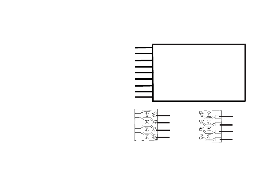
Decoder-Einbau 60942 oder 60962
Vor dem Einbau ist die Lokomotive auf einwandfreie mechanische und elektrische Funktion zu prüfen. Gegebenenfalls
muss die Lokomotive vor dem Umbau repariert werden.
Fahrzeuge ohne Schnittstelle
Löten Sie zuerst die Kabel an den Stromabnehmern (Schleifer), Motor und der Beleuchtung ab. Danach bauen Sie den
alten Decoder oder Umschalter aus. Positionieren Sie den
neuen Decoder, löten Sie die Kabel gemäß nebenstehendem
Schema an.
Ist die Beleuchtung direkt auf die Fahrzeugmasse geführt,
empfehlen wir, diese gegenüber der Fahrzeugmasse zu
isolieren. Verwenden Sie dazu die Steckfassung E604180
und die Glühlampe E610080. Damit erreichen Sie eine
flackerfreie Beleuchtung.
Ist Ihr Fahrzeug mit LED Beleuchtung ausgestattet, müssen
unbedingt Vorwiderstände eingebaut werden. Die Vorwiderstände sind je nach Strom und Bauform unterschiedlich.
Ermitteln Sie die richtigen Werte für Ihre LED. Fragen Sie
hierzu gegebenenfalls Ihren Fachhändler.
Wollen Sie Ihr Fahrzeug nachträglich mit LED beleuchten,
sind die Kathoden (-) der LED mit dem Lichtausgang zu
verbinden. Vorwiderstand nicht vergessen! Die Anoden (+)
sind an den gemeinsamen Leiter (blau) anzuschließen.
Der gemeinsame Rückleiter (blau) darf nicht mit der Fahrzeugmasse verbunden werden.
Die Vorgehensweise ist für den Decoder 60962 und für die
Schnittstellenplatine aus dem Set 60942 identisch.
Bitte beachten Sie jedoch unbedingt die jeweiligen Hinwei-
se zu den Kabelfarben.
60962
Beachten Sie, dass die Kabelfarben am Decoder der NEM
Norm entsprechen. Eine Gegenüberstellung des MärklinFarbschemas finden Sie nachfolgend (Seite 6).
grau Motoranschluss 2
schwarz Stromabnahme links
weiß Beleuchtung vorn
grün Funktion 1
blau Gemeinsamer Leiter für Beleuchtung
gelb Beleuchtung hinten
rot Stromabnahme rechts (Mittelschleifer)
orange Motoranschluss 1
violett Funktion 2
Lötpads oben
1
8
4 schwarz
3 grün
2 gelb
1 orange
Lötpads unten
8
1
8 rot
7 blau
6 weiß
5 grau
Fahrzeuge mit NEM Schnittstelle 8 polig.
Löten Sie gemäß obiger Zeichnung die Kabel an die
entsprechenden Lötpads an. Stecken sie den Stecker in die
Schnittstelle, Positionierung beachten.
Hinweise zur Beleuchtung siehe Decoder 60942.
5
Page 6
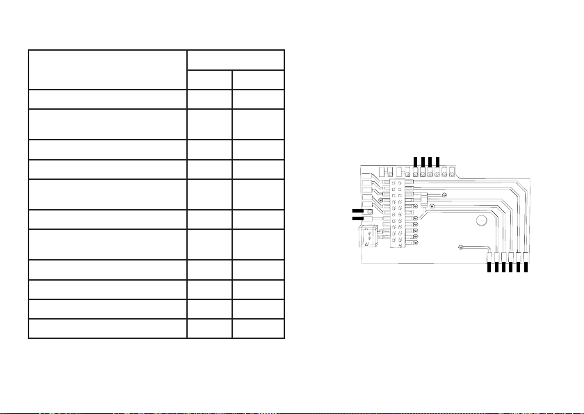
Gegenüberstellung der Kabelfarben
Bezeichnung Kabelfarbe
NEM Märklin
Motoranschluss 2 grau blau
2Leiter Stromabnahme Gleis links
3Leiter Stromabnahme Gleis außen
Beleuchtung vorn weiß grau
Funktion 1 grün braun/rot
Gemeinsamer Leiter für
Beleuchtung
Beleuchtung hinten gelb gelb
2Leiter Stromabnahme Gleis rechts
3Leiter Stromabnahme Gleis Mitte
Motoranschluss 1 orange grün
Aux 2 (physikalischer Ausgang) violett braun/grün
Aux 3 (physikalischer Ausgang) braun/gelb
Aux 4 (physikalischer Ausgang) braun/weiß
6
schwarz braun
blau orange
rot rot
60942
Halteplatte festschrauben, Kabel entsprechend an die
Anschlüsse von Motor, Schleifer und eventuellen Funktionen
löten.
Kabelfarben entsprechen dem Märklin-Standard,
Vergleichstabelle zu NEM siehe Tabelle.
braun/rot
braun/grün
braun/gelb
braun/weiß
orange
gelb
rot
blau
grau
grün
braun
orange
Wenn die Beleuchtung mit dem Rückleiter über die
Fahrzeugmasse erfolgt, kann es teilweise zum Flackern
der Beleuchtung kommen. Wenn dies nicht erwünscht ist,
muss die Beleuchtung isoliert werden. Wir empfehlen, die
Glühlampe gegen die Steckfassung 604180 und Glühlampe
610080 zu tauschen. Der Rückleiter wird dann an das orange
Kabel angeschlossen.
Page 7
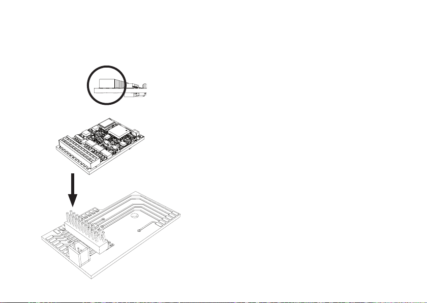
Decoder einstecken, auf richtigen Einbau achten. Modell
noch ohne Gehäuse auf dem Programmiergleis einer Prüfung unterziehen. Wenn der Decoder einwandfrei arbeitet,
kann das Gehäuse montiert werden.
!
Multiprotokollbetrieb
Analogbetrieb
Der Decoder kann auch auf analogen Anlagen oder Gleisabschnitten betrieben werden. Der Decoder erkennt die analoge Wechsel- oder Gleichspannung (AC/DC) automatisch
und passt sich der analogen Gleisspannung an. Es sind alle
Funktionen, die unter mfx oder DCC für den Analogbetrieb
eingestellt wurden aktiv (siehe Digitalbetrieb).
Digitalbetrieb
Die mLD LokDecoder sind Multiprotokolldecoder. Der
Decoder kann unter folgenden Digital-Protokollen eingesetzt
werden: mfx, DCC, fx (MM),
Das Digital-Protokoll mit den meisten Möglichkeiten ist das
höchstwertige Digital-Protokoll. Die Reihenfolge der Digital-
Protokolle ist in der Wertung fallend:
Priorität 1: mfx
Priorität 2: DCC
Priorität 3: fx (MM)
Hinweis: Digital-Protokolle können sich gegenseitig beein-
fl ussen. Für einen störungsfreien Betrieb empfehlen wir,
nicht benötigte Digital-Protokolle mit CV 50 zu deaktivieren.
Deaktivieren Sie, sofern dies Ihre Zentrale unterstützt, auch
dort die nicht benötigten Digital-Protokolle.
Werden zwei oder mehrere Digital-Protokolle am Gleis
erkannt, übernimmt der Decoder automatisch das höchstwertige Digital-Protokoll, z.B. mfx/DCC, somit wird das
7
Page 8

mfx-Digital-Protokoll vom Decoder übernommen (siehe
vorherige Tabelle).
Hinweis: Beachten Sie, dass nicht alle Funktionen in allen
Digital-Protokollen möglich sind. Unter mfx und DCC können
einige Einstellungen von Funktionen, welche im AnalogBetrieb wirksam sein sollen, vorgenommen werden.
Brems-/Signalhalteabschnitt fx(MM), mfx
Die Bremsmodule legen im wesentlichen eine Gleichspannung an das Gleis. Erkennt der Decoder eine solche Gleichspannung am Gleis, bremst er mit der eingestellten Verzögerung ab. Erkennt der Decoder wieder ein Digital-Protokoll,
beschleunigt er auf die eingestellte Geschwindigkeit.
Soll das automatische Erkennen der Bremsstrecken angewandt werden, wird empfohlen, den DC-Betrieb auszuschalten (siehe CV Beschreibung).
mfx-Protokoll
Adressierung
• Keine Adresse erforderlich, jeder Decoder erhält eine
einmalige und eindeutige Kennung (UID).
• Der Decoder meldet sich an einer Central Station oder
Mobile Station mit seiner UID automatisch an.
Programmierung
• Die Eigenschaften können über die grasche Oberäche
der Central Station bzw. teilweise auch mit der Mobile
Station programmiert werden.
• Es können alle Conguration Variablen (CV) mehrfach
gelesen und programmiert werden.
8
• Die Programmierung kann entweder auf dem Haupt- oder
dem Programmiergleis erfolgen.
• Die Defaulteinstellungen (Werkseinstellungen) können
wieder hergestellt werden.
• Funktionsmapping: Funktionen können mit Hilfe der
Central Station 60212 (eingeschränkt) und mit der Central
Station 60213/60214/60215 beliebigen Funktionstasten
zugeordnet werden (Siehe Hilfe in der Central Station).
fx-Protokoll (MM)
Adressierung
• 4 Adressen (eine Hauptadresse und 3 Folgeadressen)
• Adressbereich:
1 - 255 abhängig vom Steuergerät/Zentrale
• Hauptadresse ist manuell programmierbar
• Die Folgeadressen sind ein-, ausschalt- und einstellbar
und sind manuell oder automatisch programmierbar.
• Über diese vier Adressen sind alle 16 Funktionen schaltbar.
Programmierung
• Die Eigenschaften des Decoders können über die Programmierung der Configuration Variablen (CV) mehrfach
programmiert werden. Das Lesen der CVs ist nicht
möglich.
• Die CV-Nummer und der CV-Wert werden direkt eingegeben.
• Programmierung der CV nur auf dem Programmiergleis.
• Die Defaulteinstellungen (Werkseinstellungen) können
wieder hergestellt werden.
Page 9

• 14 bzw. 27 Fahrstufen programmierbar
• Die ersten vier Funktionen und das Licht sind über die
Hauptadresse immer schaltbar, weitere Funktionen sind
in Abhängigkeit der Folgeadressen nutzbar.
• Alle Einstellungen aus dem Funktionsmapping der mfx-
oder DCC-Programmierung werden für fx (MM) übernommen.
Automatische Erkennung entsprechend der aktiven
•
Zusatz- oder Folgeadressen. Erkannt wird, ob die Funktion
dauerhaft ein- bzw. ausgeschaltet oder über eine Folgeadressen schaltbar ist. Dieses Funktionsmapping kann
nur im mfx- oder DCC-Protokoll festgelegt werden.
• Weitere Information, siehe CV-Tabelle fx-Protokoll.
DCC-Protokoll
Adressierung
• Kurze Adresse – Lange Adresse – Traktionsadresse
• Adressbereich: 1 - 127 kurze Adresse, Traktionsadresse
1 - 10239 lange Adresse
• Jede Adresse ist manuell programmierbar.
• Kurze oder lange Adresse wird über die CVs ausgewählt.
• Eine angewandte Traktionsadresse deaktiviert die
Standard-Adresse.
Programmierung
• Die Eigenschaften können über die Conguration Variablen (CV) mehrfach geändert werden.
• Die CV-Nummer und die CV-Werte werden direkt eingegeben.
• Die CVs können mehrfach gelesen und programmiert
werden (Programmierung auf dem Programmiergleis).
• Die CVs können beliebig programmiert werden (Programmierung auf dem Hauptgleis PoM). PoM ist nur bei den in
der CV-Tabelle gekennzeichneten CV möglich. Die Programmierung auf dem Hauptgleis (PoM) muss von Ihrer
Zentrale unterstützt werden (siehe Bedienungsanleitung
ihres Gerätes).
• Die Defaulteinstellungen (Werkseinstellungen) können
wieder hergestellt werden.
• 14 bzw. 28/126 Fahrstufen einstellbar.
• Einstellung Bremsmodus mit CV 27
• Alle Funktionen können entsprechend dem Funktions-
mapping geschaltet werden (siehe CV-Beschreibung).
• Weitere Information, siehe CV-Tabelle DCC-Protokoll.
Es wird empfohlen, die Programmierungen grundsätzlich auf
dem Programmiergleis vorzunehmen.
9
Page 10

f0 f8 f0f8
Physikalische Funktionen
Jede dieser Funktionen muss extern an die Platine angeschlossen werden. Man spricht daher von physikalischen
Funktionen. Jedem physikalischem Ausgang (AUX / Licht)
kann im Digitalbetrieb ein eigener Modus/Effekt zugeordnet
werden. Dazu stehen für jeden Ausgang drei CVs zur Verfügung. Es kann für jeden Ausgang immer nur ein Modus/
Effekt eingestellt werden. Eine ausführliche Tabelle hierzu
finden sie im Internet unter:
www.maerklin.de/de/produkte/tools_downloads/technische_infos.html
Logische Funktionen
Da diese Funktionen lediglich per Software ausgeführt
werden, wird hierfür kein physikalischer Ausgang benötigt.
Schaltbare Funktionen
Deshalb spricht man hier von einer logischen Funktion.
Anfahr-/Bremsverzögerung
• Die Beschleunigungs- und Bremszeit kann getrennt von
einander eingestellt werden.
• Die logische Funktionsabschaltung ABV kann über das
Funktionsmapping auf jede beliebige Funktionstaste
gelegt werden.
Rangiergang (RG)
• Der Rangiergang bewirkt eine Reduzierung der aktuellen
Geschwindigkeit. Dies lässt ein feinfühliges Regeln der
Lokomotive zu. Der Rangiergang kann bei mfx und DCC
über das Funktionsmapping jeder beliebigen Funktionstaste zugeordnet werden. Einstellungen siehe CV-Tabelle,
Seite 18, CV 137 bzw. für mfx im Menü der Central Station.
F4
F0
1
5
systems
STOP
mobile station
Spitzensignal function/off Funktion f0 Funktion f0
Aux 1 f1 Funktion 1 Funktion * Funktion f1 Funktion f1
Aux 2 f2 Funktion 2 Funktion * Funktion f2 Funktion f2
Rangiergang f3 Funktion 3 Funktion * Funktion f3 Funktion f3
ABV ausschalten f4 Funktion 4 Funktion * Funktion f4 Funktion f4
Aux 3 (nur 60942) — — Funktion * Funktion f5 Funktion f5
Aux 4 (nur 60942) — — Funktion * Funktion f6 Funktion f6
10
* Funktionssymbole können abweichend dargestellt sein.
Digital/Systems
Page 11
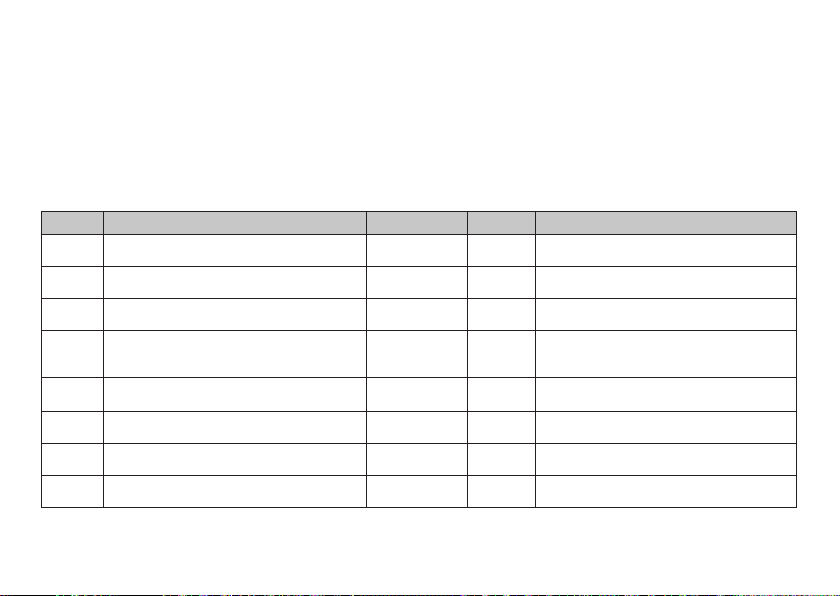
Decoder Funktionen und CV Einstellungen
Nachfolgend finden Sie die Funktionen und die CVs in
Tabellenform aufgeführt. Über diese CVs haben Sie die
Möglichkeit eine Vielzahl an Einstellungen und die Belegung
der Funktionstasten zu ändern.
Sie finden die CVs und ihre Anwendungen für die Gleisformate fx (MM) und DCC in getrennten Tabellen.
CV-Tabelle fx (MM)
Bedeutung
CV
Adresse 1 (Hauptadresse)
1
Minimalgeschwindigkeit (Vmin)
2
Anfahrverzögerung (AV)
3
Bremsverzögerung (BV)
4
Maximalgeschwindigkeit (Vmax)
5
Decoder-Reset (Default- oder Werksein-
8
stellung)
Adresse 3 (2. Folgeadresse)
17
Adresse 4 (3. Folgeadresse)
18
1-255 (1 - 80)* 78
1-255 (1 - 80)* 5
1-255 (1 - 80)* 25
1-255 (1 - 80)* 16
1-255 (1 - 63)*
1-255 (1 - 80)* 254
1-255 (1 - 80)* 253
Das Gleisformat mfx können Sie komfortabel über das
Display der CS 2 ab der Software Version 2.0, einstellen.
Gegebenenfalls müssen Sie oder Ihr Händler ein Update
ihrer Central Station 60213/60214/60215 vornehmen.
Werte
{x4}
8 -
Default
Bemerkung
Adresse ist immer aktiv und ist nicht abhän-
gig von CV 49.
Geschwindigkeit bei kleinster Fahrstufe
Wert muß kleiner sein als Vmax, CV 5.
CV-Wert multipliziert mit 0,25 ergibt die Zeit
vom Stillstand bis Maximalgeschwindigkeit.
CV-Wert multipliziert mit 0,25 ergibt die Zeit
von der Maximalgeschwindigkeit bis zum
Stillstand
Geschwindigkeit bei höchster Fahrstufe
255
Wert muß größer sein CV 2.
Wert wird nicht geschrieben.
Adresse kann de/aktiviert werden,
in Abhängigkeit von CV 49.
Adresse kann de/aktiviert werden,
in Abhängigkeit von CV 49.
* () = Control Unit 6021 {} = Die eingegebenen Werte werden x (Faktor) multipliziert.
11
Page 12

CV-Tabelle fx (MM)
Bedeutung
CV
Bremsmodus:
Bit 0 - 3: immer 0,
Bit 4 : DC Spg., Polarität entgegen der
Fahrtrichtung
27
Bit 5 : DC Spg., Polarität mit der
Fahrtrichtung
Bit 6 - 7: immer 0
Konfiguration:
Bit 0: Richtungsverhalten der Lok umkehren
0 = Richtung normal,
1 = Richtung umkehren
Bit 1: Anzahl der Fahrstufen,
29
Halbstufen 14 oder 27
0 = 14 Fahrstufen,
1 = 27 Fahrstufen/Halbstufen
Bit 2: Analogbetrieb aus-/einschalten
0 = Analog aus, 1 = Analog ein
Erweiterte Konfiguration:
Bit 0: Anzahl Adressen, LSB
Bit 1: Anzahl Adressen, MSB
49
Bit 2: automatische Folgeadressierung
(0=ein / 1=aus)
Alternative Formate:
Bit 0: Analog AC aus = 0 / Analog AC ein = 1
Bit 1: Analog DC aus = 0 / Analog DC ein = 1
50
Bit 2: DCC aus = 0 / DCC ein = 1
* () = Control Unit 6021 {} = Die eingegebenen Werte werden x (Faktor) multipliziert.
Bit 3: mfx aus = 0 / mfx ein = 1
12
Werte
0 - 48
0
0 / 16
0 / 32
0
0 - 7
0 - 7 5
0 - 15
0/1
0/2
0/4
0/8
Default
48
6
15
Bemerkung
Bremsen richtungsabhängig:
- 16 normales DCC-Verhalten
- 32 inverses DCC-Verhalten
Bremsen richtungsunabhängig:
- 48: fx/mfx - Verhalten
Das Richtungsverhalten bezieht sich auf die
Fahrtrichtung und auf das Licht.
Die Anzahl der Fahrstufen und Halbstufen
und vom Fahrgerät abhängig.
Nur Digitalbetrieb oder auch konventioneller
Betrieb. Während des Betriebes ist ein
fliegender Wechsel möglich.
0 = eine | 1 = zwei | 0 = drei | 1 = vier
0 Adr. | 0 Adr. | 1 Adr. | 1 Adr.
0 = auto. Folge ein / 1 = auto. Folge aus
Hinweis:
fx (MM) kann sich selber nicht deaktivieren.
Page 13
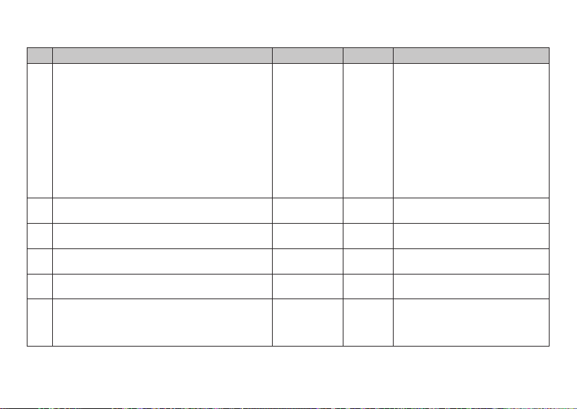
CV-Tabelle fx (MM)
Bedeutung
CV
Motortyp ... (Bit 0-4)
... Aux - Funktionsausgänge 5 und 6
... Motor - Softdrive Sinus
... Motor - ungeregelt
... Motor - Hochleistungsantrieb C90
... Motor - Glockenanker
52
... Motor - Gleichstrom DC weich
... Motor - Gleichstrom DC hart
... Motor - Gleichstrom DC Spur 1
auch Analog geregelt ... (Bit 5)
... 0: mit Analog geregelt
... 1: ohne Analog geregelt
Motorregelung - Regelreferenz
53
Motorregelung - Regelparameter K
54
Motorregelung - Regelparameter I
55
Motorregelung - Regeleinuss
56
Verschiedene Zustände speichern:
Bit 0: Funktionszustände speichern
73
Bit 1: Geschwindigkeit speichern
Bit 2: Nach Reset mit/ohne ABV anfahren
* () = Control Unit 6021 {} = Die eingegebenen Werte werden x (Faktor) multipliziert.
1
Eine Ausführliche Tabelle zum Funktionsmapping finden Sie im Internet unter:
www.maerklin.de/de/produkte/tools_downloads/technische_infos.html
1 - 255 (0 - 63)*
1 - 255 (0 - 63)*
1 - 255 (0 - 63)*
1 - 255 (0 - 63)*
Werte Default
0 - 63
0
1
2
3
4
5
6
7
0
32
{x4}
{x4}
{x4}
{x4}
150
64
64
24
0 - 7
0 / 1
0 / 2
0 / 4
Bemerkung
Auswahl eines Motortyps zur weiteren
Einstellung für die Motorregelung.
Auswahl zusätzlicher Funktions-
3
ausgänge bei einem H0-Decoder.
Funktionsweise der Motorausgänge
als weitere Auxe, siehe extra Tabelle
Absolutes Vmax für Motorkennlinie
Regelanteil P
Regelanteil I
0 = ungeregelte PWM für Sinus
(siehe auch CV 52 Motortyp)
0 = nicht speichern / 1 = speichern
7
0 = nicht speichern / 2 = speichern
0 = ohne ABV / 4 = mit ABV
oder
1.
13
Page 14
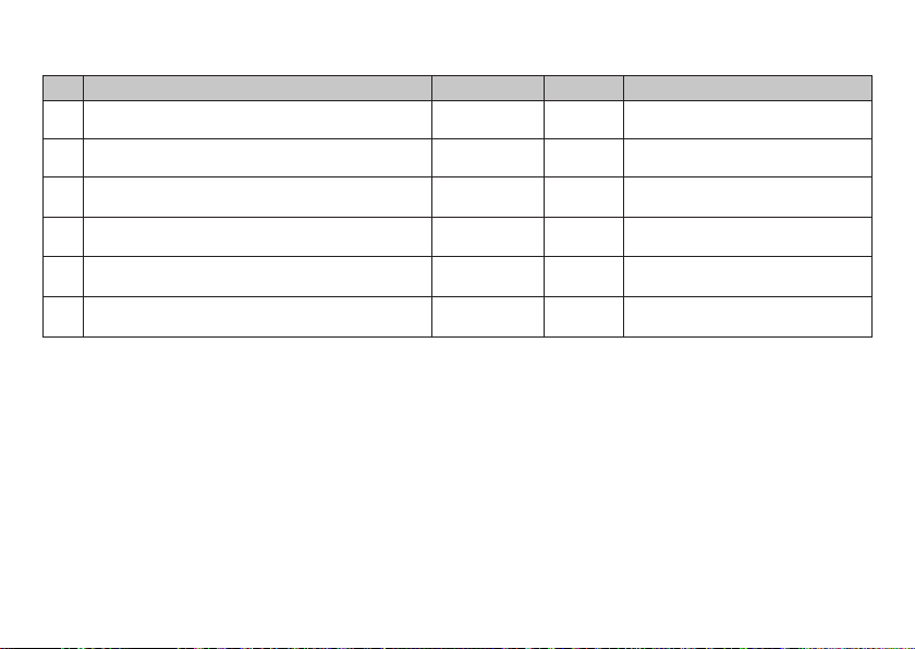
CV-Tabelle fx (MM)
Bedeutung
CV
Verschiedene Zustände speichern:
74
Bit 0: Fahrtrichtung speichern
Adresse 2 (1. Folgeadresse)
75
Analog DC Anfahrspannung
76
Analog DC Höchstgeschwindigkeit
77
Analog AC Anfahrspannung
78
Analog AC Höchstgeschwindigkeit
79
* () = Control Unit 6021 {} = Die eingegebenen Werte werden x (Faktor) multipliziert.
14
1 - 255 (1 - 63)*
1 - 255 (1 - 63)*
1 - 255 (1 - 63)*
1 - 255 (1 - 63)*
Werte Default
0/1 1
1 - 80 79
{x4}
{x4}
{x4}
{x4}
100
255
100
255
Bemerkung
0 = nicht speichern / 1 = speichern
Adresse kann de/aktiviert werden,
in Abhängigkeit von CV 49.
Hinweis für die CS1: (140)
Die CS1 zeigt den Wert invertiert an.
Hinweis für die CS1: (140)
Die CS1 zeigt den Wert invertiert an.
Page 15
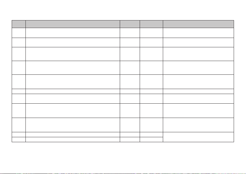
CV-Tabelle DCC
CV Bedeutung Werte Default Bemerkung
1 Hauptadresse 1 - 127 3
PoM
Minimalgeschwindigkeit (Vmin) 0 - 255 5
2
PoM
3
Anfahrverzögerung (AV) 0 - 255 25
PoM
4
Bremsverzögerung (BV) 0 - 255 16
PoM
5
Maximalgeschwindigkeit (Vmax) 0 - 255 255
7 Hersteller Versionsnummer (Softwareversion) – Nur lesen
Hersteller Kennung / ID
8
Decoder-Reset (Default- oder Werkseinstellung)
PoM
13
Funktionen F1 - F8 bei alternativem Gleissignal 0 - 255 0
PoM
Funktionen FL, F9 - F15 bei alternativem Gleissignal 0 - 255 1
14
–
8
17 Erweiterte Adresse, höherwertige Byte 192 - 231 192
18 Erweiterte Adresse, niederwertige Byte 0 - 255 128
PoM muss vom Steuergerät unterstützt werden
Kurze Adresse 1 - 127
Wenn CV29 / Bit 5 = 0
Wert muss kleiner sein als Vmax, CV 5.
(siehe CV 67)
CV-Wert multipliziert mit 0,9 ergibt die
Zeit vom Stillstand bis Maximalgeschwindigkeit.
CV-Wert multipliziert mit 0,9 ergibt die
Zeit von Maximalgeschwindigkeit bis
Stillstand.
Geschwindigkeit bei höchster Fahrstufe.
Wert muss größer sein als Vmin, CV 2.
(siehe auch CV 94)
131–Nur lesen
Wert kann nicht gelesen werden
0 = Fkt. MM oder Analog aus
1 = Fkt. MM oder Analog ein
Bit 7-0 [ F8 F7 F6 F5 F4 F3 F2 F1 ]
0 = Fkt. MM oder Analog aus
1 = Fkt. MM oder Analog ein
Bit 7-0 [ F15 F14 F13 F12 F11 F10 F9 FL ]
Lange Adresse 1 - 10239 (128)
Wenn CV29 / Bit 5 = 1
15
Page 16

CV-Tabelle DCC
CV Bedeutung Werte Default Bemerkung
1 - 127 = Traktionsadresse
19 Traktionsadresse 0 - 255 0
PoM
21
Funktionen F1 - F8 bei Traktion 0 - 255 0
PoM
Funktionen FL, F9 - F15 bei Traktion 0 - 255 0
22
Bremsmodus:
Bit 0 - 3: immer 0,
PoM
Bit 4 : DC Spg., Polarität entgegen der Fahrtrichtung
27
Bit 5 : DC Spg., Polarität mit der Fahrtrichtung
Bit 6 - 7: immer 0
Konfiguration:
Bit 0: Richtungsverhalten der Lok umkehren
0 = Richtung normal,
1 = Richtung umkehren
Bit 1: Fahrstufen 14 oder 28/128 wählen
0 = 14 Fahrstufen,
PoM
1 = 28/128 Fahrstufen
29
Bit 2: Analogbetrieb aus-/einschalten
0 = Analog aus,
1 = Analog ein
Bit 5: Kurze / Lange Adresse wählen
0 = kurze Adresse,
1 = lange Adresse
PoM muss vom Steuergerät unterstützt werden
0 - 48
0
0 / 16
0 / 32
0
0 - 39
0 / 1
0 / 2
0 / 4
0 / 32
16
0 = keine Traktion
+128, Bit 7 = Richtung umpolen bei
Traktion
0 = Fkt. # nur für Lokadresse
1 = Fkt. # auch für Traktionsadresse
Bit 7-0 = [ F8 F7 F6 F5 F4 F3 F2 F1 ]
0 = Fkt. # nur für Lokadresse
1 = Fkt. # auch für Traktionsadresse
Bit 7-0 = [ F15 F14 F13 F12 F11 F10 F9 FL ]
Bremsen richtungsabhängig:
-
48
- 32 inverses DC-Verhalten
Bremsen richtungsunabhängig:
- 48 fx/mfx Leiterverhalten
Das Richtungsverhalten bezieht sich auf
die Fahrtrichtung und auf das Licht. Die
Anzahl der Fahrstufen und das Lichtbit
sind vom Fahrgerät abhängig.
6
Als Lokadresse entweder die kurze
Hauptadresse oder die lange erweiterte
Adresse.
16 normales DC-Verhalten
Page 17
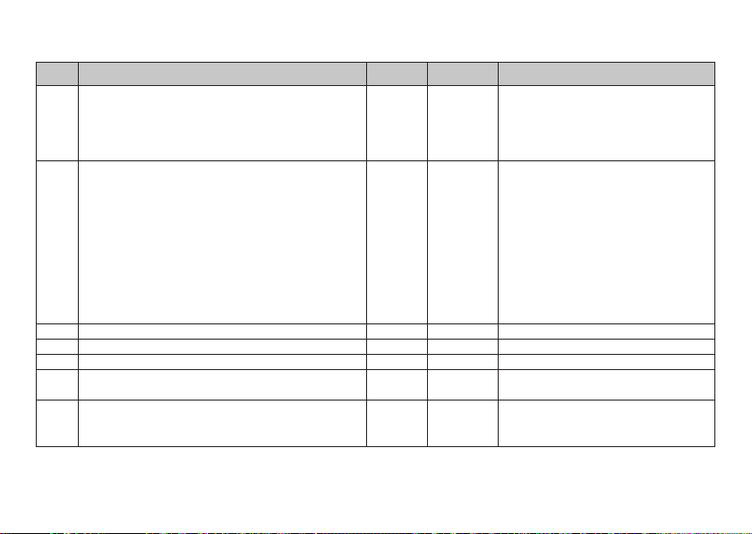
CV-Tabelle DCC
CV Bedeutung Werte Default Bemerkung
Alternative Formate:
Bit 0: Analog AC aus = 0 / Analog AC ein = 1
PoM
Bit 1: Analog DC aus = 0 / Analog DC ein = 1
50
Bit 2: fx (MM) aus = 0 / fx (MM) ein = 1
Bit 3: mfx aus = 0 / mfx ein = 1
Motortyp ... (Bit 0-4)
... Aux - Funktionsausgänge 5 und 6
... Motor - Softdrive Sinus
... Motor - ungeregelt
... Motor - Hochleistungsantrieb C90
... Motor - Glockenanker
PoM
52
... Motor - Gleichstrom DC weich
... Motor - Gleichstrom DC hart
... Motor - Gleichstrom DC Spur1
auch Analog geregelt ... (Bit 5)
... 0: mit Analog geregelt
... 1: ohne Analog geregelt
PoM
53
Motorregelung - Regelreferenz 0 - 255 150 Absolutes Vmax für Motorkennlinie
PoM
Motorregelung - Regelparameter K 0 - 255 64 Regelanteil P
54
PoM
Motorregelung - Regelparameter I 0 - 255 64 Regelanteil I
55
PoM
56
Motorregelung - Regeleinuss 0 - 255 24
PoM
Vorwärts Trimm 0 - 255 128
66
PoM muss vom Steuergerät unterstützt werden
0 - 15
0 / 1
0 / 2
0 / 4
Hinweis:
15
DCC kann sich selber nicht deaktivieren.
0 / 8
0 - 63
0
1
2
3
4
5
6
7
0
32
Auswahl eines Motortyps zur weiteren
Einstellung für die Motorregelung
3
Auswahl zusätzlicher Funktionsausgänge
bei einem H0-Decoder. Funktionsweise
der Motorausgänge als weitere Auxe,
siehe extra Tabelle.*
0 = ungeregelte PWM für Sinus
(siehe auch CV 52 Motortyp)
CV-Wert dividiert durch 128 ergibt
den Faktor, mit dem die Fahrstufe bei
Vorwärtsfahrt multipliziert wird.
* Eine Ausführliche Tabelle zum Funktionsmapping finden Sie im Internet unter:
www.maerklin.de/de/produkte/tools_downloads/technische_infos.html
oder
17
Page 18
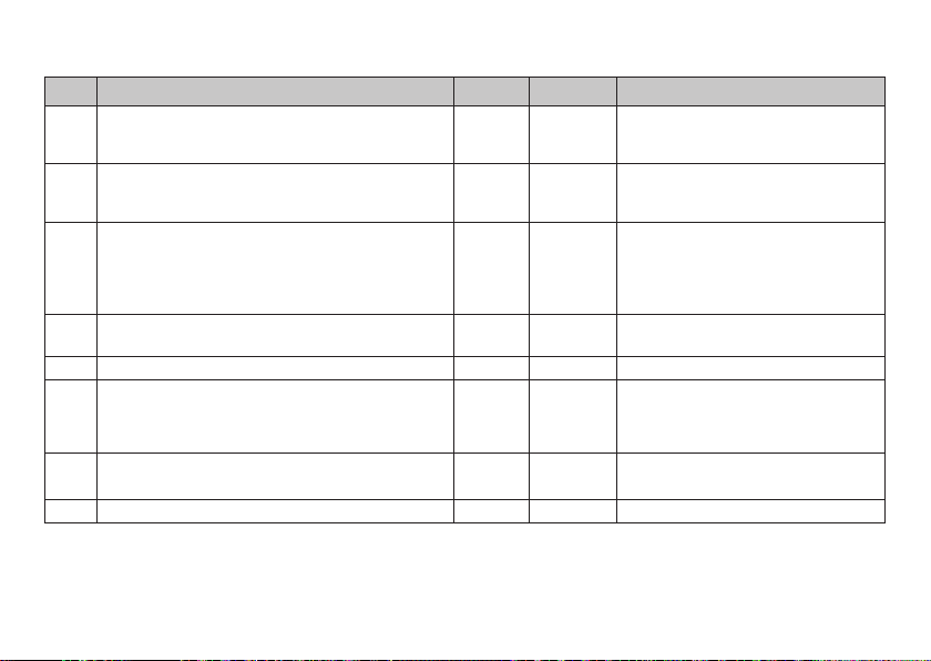
CV-Tabelle DCC
CV Bedeutung Werte Default Bemerkung
PoM
67
Geschwindigkeitstabelle Fahrstufe 1 (Vmin) bis
Geschwindigkeitstabelle Fahrstufe 28 (Vmax)
PoM
94
PoM
95
Rückwärts Trimm 0 - 255 128
PoM
physikalischer Ausgang (Mapping): Licht vorne Modus
112
PoM
physikalischer Ausgang (Mapping): Licht vorne
113
Dimmer
PoM
physikalischer Ausgang (Mapping): Licht vorne
114
Periode
bis
physikalischer Ausgang (Mapping): Licht hinten ,
PoM
135
Aux 1 bis Aux 6 (jeweils im 3er Block)
PoM
137
Rangiergang 0 - 128 128 128 = 50% Fahrstufe, 64 = 25% Fahrstufe
Verschiedene Zustände speichern:
Bit 0= Funktionszustände speichern
PoM
173
Bit 1= Geschwindigkeit speichern
Bit 2= Nach Reset mit/ohne ABV anfahren
Verschiedene Zustände speichern:
PoM
174
Bit 0= Fahrtrichtung speichern
PoM
176
Vmin Analog DC 0 - 255 100 muss kleiner CV 177 sein
PoM muss vom Steuergerät unterstützt werden
18
0 - 255
CV-Wert dividiert durch 128 ergibt
den Faktor, mit dem die Fahrstufe bei
Rückwärtsfahrt multipliziert wird.
0 - 16
0 - 255
0 - 255
255
1
20
Siehe Tabelle*
Siehe Tabelle*
0 - 7
0 / 1
0 / 2
0 / 4
0 - 1 1
* Eine Ausführliche Tabelle zum Funktionsmapping finden Sie im Internet unter:
www.maerklin.de/de/produkte/tools_downloads/technische_infos.html
0 = nicht speichern, Wert = speichern,
7
einzelne Werte müssen addiert werden.
0 = nicht speichern
1 = speichern
Page 19
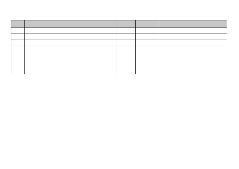
CV-Tabelle DCC
CV Bedeutung Werte Default Bemerkung
PoM
177
Vmax Analog DC 0 - 255 255 muss größer CV 176 sein
PoM
178
Vmin Analog AC 0 - 255 100 muss kleiner CV 179 sein
PoM
179
Vmax Analog AC 0 - 255 255 muss größer CV 178 sein
PoM
257
Funktionszuordnung (Mapping): Funktion FL vorwärts A
PoM
Funktionszuordnung (Mapping): Funktion FL vorwärts B
258
PoM
Funktionszuordnung (Mapping): Funktion FL vorwärts C
259
PoM
Funktionszuordnung (Mapping): Funktion FL vorwärts D
260
Funktionszuordnung (Mapping): Funktion Fahrt rück-
bis 445
wärts D
PoM muss vom Steuergerät unterstützt werden
0 - 255
0 - 255
0 - 255
0 - 255
— — Siehe Tabelle
1
Eine Ausführliche Tabelle zum Funktionsmapping finden sie im Internet unter:
www.maerklin.de/de/produkte/tools_downloads/technische_infos.html
1
0
0
0
Siehe Tabelle
1
1
19
Page 20

Störungen beheben
Bei Betrieb mit verschiedenen Protokollen kann es zu
gegenseitigen Störungen kommen. – Es wird empfohlen, die
Anzahl der Protokolle zu reduzieren. Nicht benötigte Protokolle im Lokdecoder und falls möglich auch in der Zentrale
deaktivieren.
Lok ruckelt und stockt – CV Einstellung für Motorvariante
prüfen, gegebenenfalls ändern oder Reset auf die Werksein-
stellungen durchführen.
Lok fährt analog nicht - automatische Analog-Erkennung
ist deaktiviert und muss wieder aktiviert werden (siehe
CV-Tabelle).
Lok (Decoder) reagiert nicht - Verkabelung und Lötstellen
prüfen, gegebenenfalls nacharbeiten. Schnittstelle des
Decoders auf festen Kontakt und Einbaurichtung prüfen.
mfx/DCC Betrieb: Auf der Anlage stehende Lokomotiven
fahren unvermittelt bei der mfx Anmeldung los. — Bei
diesen Lokomotiven die automatische Analog-Erkennung
deaktivieren.
20
Entsorgung
Hinweise zum Umweltschutz: Produkte,
die mit dem durchgestrichenen Mülleimer
gekennzeichnet sind, dürfen am Ende ihrer
Lebensdauer nicht über den normalen Haushaltsabfall entsorgt werden, sondern müssen
an einem Sammelpunkt für das Recycling
von elektrischen und elektronischen Geräten abgegeben
werden. Das Symbol auf dem Produkt, der Bedienungsanleitung oder der Verpackung weist darauf hin. Die Werkstoffe
sind gemäß ihrer Kennzeichnung wiederverwertbar. Mit
der Wiederverwendung, der stofflichen Verwertung oder
anderen Formen der Verwertung von Altgeräten leisten Sie
einen wichtigen Beitrag zum Schutze unserer Umwelt. Bitte
erfragen Sie bei Ihrer Gemeindeverwaltung die zuständige
Entsorgungsstelle.
Garantie
Gewährleistung und Garantie gemäß der beiliegenden
Garantieurkunde.
• Für Reparaturen wenden Sie sich bitte an Ihren Märklin-
Fachhändler oder an
Gebr. Märklin & Cie. GmbH
Reparaturservice
Stuttgarter Str. 55 - 57
73033 Göppingen/Deutschland
Tel: 09001 608 222 (nur aus dem Inland*)
E-Mail: [email protected]
* Anruf 49CT/Min. bei Anruf aus dem Festnetz, Handytarife
können davon deutlich nach oben abweichen.
Page 21
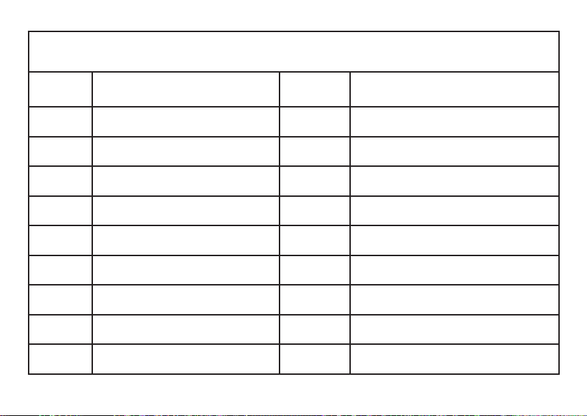
Meine persönlichen Decoder-Einstellungen
Lokomotive:
Adresse
Adress
CV -
CV - CV -
CV - CV -
CV - CV -
CV - CV -
CV - CV -
CV - CV -
CV - CV -
CV - CV -
CV - CV -
My personal decoder settings
Locomotive:
21
Page 22

Using the Product as Intended
The 60942/60969 decoders are for converting Märklin/Trix H0
locomotives to digital.
! Not suitable for motors with fi eld-wound coils. Locomoti-
ves with these motors must be converted with the appropriate motor retrofi t kits, item numbers 60942 or 60962.
! Important: The following locomotives (locomotive-specifi c
decoder) cannot be converted with this decoder.
Items:
26410
26453
26490
26557
26561
26562
29094 (only E 94)
29440 (only E 10)
29500 (only E 50)
37010
37011
37044
37226
37227
37239
37274
37275
37321
22
37346
37403
37404
37435
37485
37501
37504
37505
37530
37542
37573
37574
37575
37580
37581
37607
37733
37734
37777
37786
37787
37790
37791
37867
37940
37941
37993
39014
39022
39051
39081
39110
39123
39140
39185
39303
39340
39343
39390
39392
39393
39399
39404
39441
39563
39564
39565
39643
39836
39837
39838
39896
39972
39986
Contents as Delivered
1 decoder
1 Circuit board with a 21-pin connector
1 NEM 8-pole connector
1 Circuit board retainer (only 60942)
1 Screw (only 60942)
1 Adhesive pad (only 60962)
Installation instructions
Warranty card
Tools also needed for the installation procedure include:
regular and cross-point screwdrivers, tweezers, and soldering station with a maximum soldering temperature of up to
30 watts / 300˚Celsius / 572˚Fahrenheit with a fi ne tip, solder-
ing ux for electronics (0.5 - 1 mm / 0.02” – 0.04” diameter),
de-soldering braid or a de-soldering pump.
Safety Notes
•
WARNING! Sharp edges and points required for operation.
• Do wiring and assembly work only on a voltage-free
or grounded work mat. Failure to do this can lead to
dangerous static charge from your body and to damage
to the components.
• Operate the decoder only with the authorized voltage
(see technical data).
There is a danger of burning yourself when working
with a soldering station.
Page 23

Technical Information
• Continuous current load at the motor output ≤ 1.1 amps
• Current load at the light outputs ≤ 250 milliamps
• Current load at AUX 1 – AUX 4 each ≤ 250 milliamps
• Current load at AUX + lights (total) ≤ 300 milliamps
• Current load for motor and AUX 5/6 ≤ 1.1 amps
• Maximum total load ≤ 1.6 amps
• Maximum voltage ≤ 40 volts
• Sound performance (at 4 Ω /8 Ω) 2.3 watts / 1.2 watts
• Short circuit and overload protection at the outputs lights
front (LV), lights rear (LH), AUX 1 – AUX 4 and at the motor
outputs.
Functions
The mSD SoundDecoder is a sound decoder with very
extensive setting and adaptation possibilities. Additional
sound functions are available. This decoder can be updated.
The requirement for this is an appropriate controller
(60213/60214/60215 Central Station, software Version 2.0,
track format processor GFP 2.0 or higher).
The settings and digital functions can only be used in digital
operation. However, the same possibilities are not available
in all protocols.
These instructions describe the installation and the possible
settings for the 60942 and 60962 decoders. Unless otherwise
stated, the functions refer to both decoders.
Capable of multi-protocols (fx (MM), mfx, DCC, and AC/DC).
•
• Automatic system recognition. The address assigned to
each system must be used for operation.
• Acceleration and braking delay can be set separately
from each other. Any function button desired can be assigned using the function mapping.
• Typical sound backdrops for diesel and electric locomotives are included.
• Variable motor feedback control is available in digital as
well as in analog operation.
• 6090, 60901, DC, Sinus and can motors with bell-shaped
armatures are supported. See necessarily this table on
page 23.
• Function mapping included.
• Can be updated with the CS2 (Software 2.0, track format
processor GFP 2.0 or higher).
• Programming on the Main (PoM) this type of programming must be supported by the controller. Please note the
instructions for your controller when doing this.
• Switching range can be set.
• Braking / signal stopping block recognition is available in
digital operation.
23
Page 24
Decoder Installation
The locomotive must be checked before installing the decoder to make sure that it (locomotive) is in good mechanical
and electrical condition. There are situations when the locomotive will have to be repaired before installing the decoder.
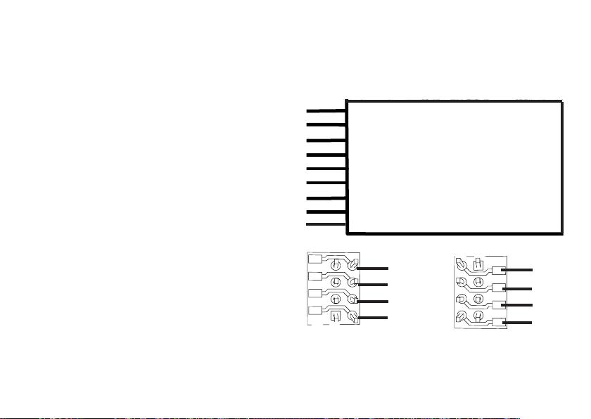
Locomotives / Powered Rail Cars with a Connector
First unsolder the wires to the current pickups (pickup
shoe(s)), motor, and the lights. After that remove the old
decoder or reverse unit. Position the new decoder and solder
the wires according to the diagram nearby.
If the lights are grounded to the locomotive’s or powered rail
car’s ground on the frame, we recommend that the lights
be insulated from the locomotive ground. To do this, use the
E604180 plug-in bulb holder(s) and E610080 light bulb(s). This
will give you flicker-free lighting.
If your locomotive or powered rail car is equipped with LED
lighting, then series resistors must absolutely be installed.
Series resistors differ according to the current the design.
Find out the correct values for your LEDs. You may have to ask
your specialty dealer about this.
If you want to retrofit your locomotive or powered rail car
with LEDs, the cathodes (-) on the LED are connected to the
light output on the decoder. Don’t forget series resistors! The
anodes (+) are connected to the common wire (blue).
The common ground return (blue) must not be connected to
the ground for the locomotive or powered rail car.
This procedure is identical for the 60962 decoder and for the
connector board from the 60942 set. Make sure that you pay
absolute attention to the notes for the colors of the wires for
24
each decoder.
60962
Please note that the colors for the wires conform to the
European NEM standard. A cross reference of the Marklin
color scheme can be found page 26.
gray Motor Connection 2
black Conductor Current Pickup, Left
white Front Lights
green Function 1
blue Common Wire for Lights
yellow Rear Lights
red Conductor Current Pickup, Right / Center
orange Motor Connection 1
violet Function 2
Solder pads above
4 schwarz
3 grün
2 gelb
1
8
1 orange
Locomotives or powered rail cars with NEM 8-pin connector.
Solder pads below
8
1
8 rot
7 blau
6 weiß
5 grau
Solder the wires to the correct solder pads according to the
diagram above. Insert the plug into the connector while paying attention to the positioning.
Information on lighting see Dceoder 60942
Page 25
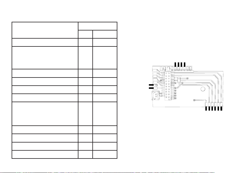
Cross Referencing the Colors for the Wires
Description Wire Color
NEM Märklin
Motor Connection 2 gray blue
2- Conductor Current Pickup,
Track, Left
3- Conductor Current Pickup,
Track, Outer
Front Lights white gray
Function 1 green brown/red
Common Wire for Lights blue orange
Rear Lights yellow yellow
2- Conductor Current Pickup,
Track, Right
3- Conductor Current Pickup,
Track, Center
Motor Connection 1 orange green
Aux 2 (physical output) violet
Aux 3 (physical output) brown/Yellow
Aux 4 (physical output) brown/white
black brown
red red
brown/green
60942
Screw down the mounting plate and solder the wires to the
motor connections, pickup(s), and any functions.
The colors for the wires correspond to the Märklin Standard;
for a comparison table for NEM.
brown/red
brown/green
braown7yellow
brown/wihte
orange
yellow
red
blue
gray
green
brown
orange
If the lighting is grounded to the locomotive or powered
rail car’s frame, this may cause flickering. If you don’t want
this, then the lighting must be insulated. We recommend
replacing the light bulb(s) with the 604180 plug-in socket(s)
and the 610080 light bulb(s). The ground is then connected to
the orange wire.
25
Page 26
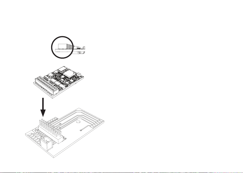
Plug the decoder into the circuit board and make sure you
have plugged it in correctly. Place the model, with the body
left off, on the programming track and test it. If the decoder
works with no problems, the body can be put on the locomotive.
!
26
Multi-Protocol Operation
Analog Operation
This decoder can also be operated on analog layouts or
areas of track that are analog. The decoder recognizes
alternating current or direct current voltage (AC/DC) and
automatically adapts to the analog track voltage. All functions that were set under mfx or DCC for analog operation
are active (see Digital Operation).
Digital Operation
The mSD sound decoders are multi-protocol decoders.
These decoders can be used under the following digital
protocols: mfx, DCC, fx (MM).
The digital protocol with the most possibilities is the highest
order digital protocol. The sequence of digital protocols in
descending order is:
Priority 1: mfx
Priority 2: DCC
Priority 3: fx (MM)
Note: Digital protocols can infl uence each other. For troublefree operation, we recommend deactivating those digital
protocols not needed by using CV 50. Deactivate unneeded
digital protocols at this CV if your controller supports this
function.
If two or more digital protocols are recognized in the track,
the decoder automatically takes on the highest order digital
protocol, example: mfx/DCC; the decoder takes on the mfx
digital protocol (see previous table).
Page 27

Note: Please note that not all functions are possible in all
digital protocols. Several settings for functions, which are
supposed to be active in analog operation, can be done
under mfx and DCC.
Braking / Signal Stopping Block (MM, fx, mfx)
The braking module essentially applies DC voltage to the
track. If the decoder recognizes a DC voltage of this kind in
the track, it brakes with the delay that has been set. If the
decoder recognizes a digital protocol again, it accelerates
at the speed that has been set.
If automatic recognition in braking areas is to be used, we
recommend shutting the DC operation off (see CV description).
mfx Protocol
Addresses
• No address is required; each decoder is given a one-
time, unique identifier (UID).
• The decoder automatically registers itself on a Central
Station or a Mobile Station with its UID.
Programming
• The characteristics can be programmed using the
graphic screen on the Central Station or also partially
with the Mobile Station.
• All of the Conguration Variables (CV) can be read and
programmed repeatedly.
• The programming can be done either on the main track or
the programming track.
• The default settings (factory settings) can be produced
repeatedly.
• Function mapping: Functions can be assigned to any of
the function buttons with the help of the 60212 Central
Station (with limitations) and with the 60213/60214/60215
Central Station (See help section in the Central Station).
fx (Motorola) Protocol
Addresses
4 addresses (a main address and 3 consecutive addresses)
•
• Address range:
1 - 255 depending on the controller / central controller
• The main address can be programmed manually.
• The consecutive addresses can be turned on, turned off,
set and can be programmed manually or automatically.
• All 16 functions can be controlled by means of the four
addresses.
Programming
• The characteristics can be programmed for the decoder
can be programmed repeatedly using the programming
for the Conguration Variables (CV). Reading the CVs is
not possible.
• The CV numbers and the CV values are entered directly.
• Program the CVs only on the programming track.
• The default settings (factory settings) can be produced
repeatedly.
• 14 or 27 speed levels can be programmed.
27
Page 28

• The rst four functions and the lights can always be controlled by means of the first address; additional functions
can be used, depending on the consecutive addresses.
• All of the settings from the function mapping for mfx or
DCC programming are taken on for fx (Motorola).
• Automatic recognition corresponding to the active additional or consecutive addresses. What is recognized is
whether the function can be turned on or off continuously
by means of a consecutive address. This function mapping can only be determined in the mfx or DCC protocol.
• See the CV description for the fx protocol for additional
information.
DCC Protocol
Addresses
• Short address – long address – multiple unit address
• Address range:
1 - 127 for short address and multiple unit address,
1 - 9999 for long address
• Every address can be programmed manually.
• A short or a long address is selected using the CVs.
• A multiple unit address that is being used deactivates the
standard address.
Programming
• The characteristics can be changed repeatedly using the
Configuration Variables (CV).
• The CV numbers and the CV values are entered directly.
• The CVs can be read and programmed repeatedly. (Pro-
gramming is done on the programming track).
28
• The CVs can be programmed in any order desired. (Programming can be done on the main track PoM). The PoM
can only be done with those designated in the CV table.
Programming on the main track PoM must be supported
by your central controller (Please see the description for
this unit).
• The default settings (factory settings) can be produced
repeatedly.
• 14/28 or 126 speed levels can be set.
• All of the functions can be controlled according to the
function mapping (see CV description).
• See the CV description for the DCC protocol for additional
information.
We recommend that in general programming should be
done on the programming track.
Page 29
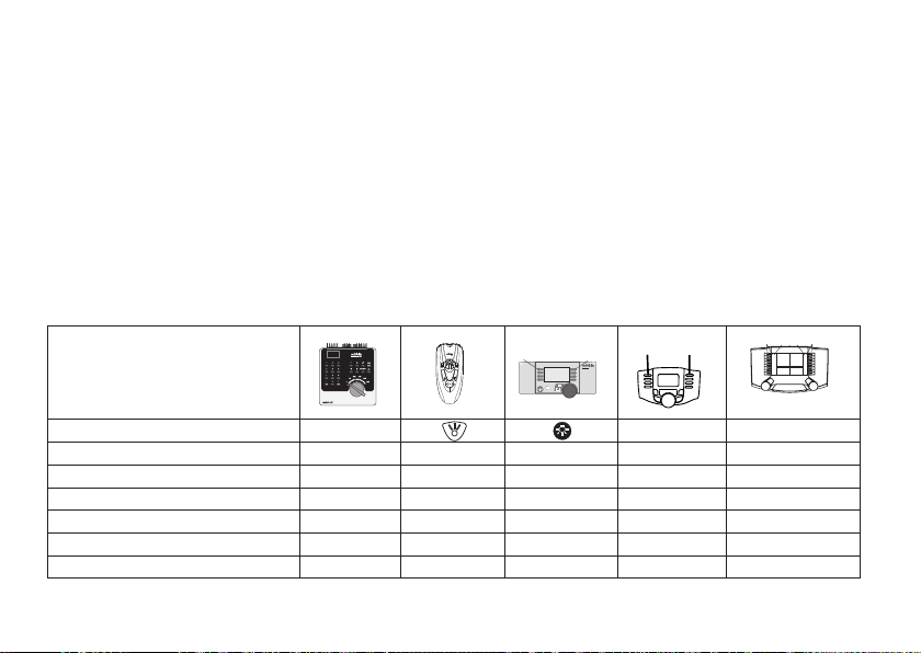
Physical Functions
f0 f8 f0f8
Each of these functions must be connected externally to the
circuit board. We therefore speak of physical functions. A
unique mode/effect can be assigned to each physical output
(AUX / lights) in digital operation. Three CVs are available for
each output for this purpose. Only one mode/effect can be
set for each output. A complete table for this can be found
on the Internet at:
www.maerklin.de/de/produkte/tools_downloads/technische_infos.html
Logic Functions
Since these functions are only executed by software, no
physical output is required for them. We therefore speak
Controllable Functions
here of a logic function.
Acceleration/Braking Delay
• The acceleration and braking time can be set separately
from each other.
• The logic function ABV can be assigned to any function
button by using the function mapping.
Switching Range (RG)
• The switching range causes a reduction in the current
speed of the locomotive. This allows a fine touch in the
controlling the locomotive. The switching range can be
assigned in mfx and DCC to any function button by using
the function mapping. See table on page 39 for setting
CV, CV 137 or mfx menu for the Central Station.
F4
F0
1
5
systems
STOP
mobile station
Headlights function/off Funktion f0 Funktion f0
Aux 1 f1 Funktion 1 Funktion * Funktion f1 Funktion f1
Aux 2 f2 Funktion 2 Funktion * Funktion f2 Funktion f2
Switching Range f3 Funktion 3 Funktion * Funktion f3 Funktion f3
ABV out f4 Funktion 4 Funktion * Funktion f4 Funktion f4
Aux 3 (nur 60942) — — Funktion * Funktion f5 Funktion f5
Aux 4 (nur 60942) — — Funktion * Funktion f6 Funktion f6
* Function symbols may be displayed in different order.
Digital/Systems
29
Page 30
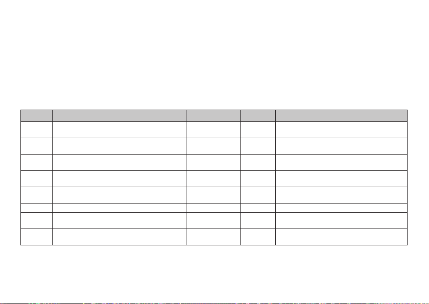
Decoder functions and CV settings
The following pages have the functions and the CVs
presented in tabular form. These CVs can be given a number
of settings and can be assigned to a number of function
buttons.
You‘ll find the CVs and their applications for the track
formats fx (MM) and DCC in separate tables.
CV Table for fx (MM)
Explanation Values Default Notes
CV
Address 1 (main address) 1-255 (1 - 80)* 78
1
Minimum speed (Vmin) 1-255 (1 - 80)* 5
2
Acceleration delay (AV)
3
Braking delay (BV)
4
Maximum speed (Vmax)
5
Decoder reset (default or factory setting) 8 - Value is not written.
8
Address 3 (2nd consecutive address) 1-255 (1 - 80)* 254
17
Address 4 (3rd consecutive address) 1-255 (1 - 80)* 253
18
* () = 6021 Control Unit {} = the values entered are multiplied times “x” (factor).
30
1-255 (1 - 80)*
[0,00s - 20,00sec.]
1-255 (1 - 80)*
[0,00s - 20,00s]
1-255 (1 - 63)*
{x4}
The track format mfx can be easily set by using the
display on the CS 2 with Software Version 2.0 and higher.
You or your dealer may have to install an update on your
60213/60214/60215 Central Station.
Address is always active and is not subject
to CV 49.
Speed at the smallest speed level. Value
must be smaller than Vmax, CV 5.
CV value multiplied by 0.25 gives the time
25
from complete stop to maximum speed.
CV value multiplied by 0.25 gives the time
16
from the maximum speed to absolute stop
Speed at the highest speed level. Value
255
must be greater than CV 2.
Address can be deactivated/activated
subject to CV 49.
Address can be deactivated/activated
subject to CV 49.
Page 31

CV Table for fx (MM)
Explanation
CV
Braking mode:
Bit 0 - 3 : always 0,
Bit 4 : DC voltage, polarity against the direction
of travel
27
Bit 5 : DC voltage, polarity with the direction of
travel
Bit 6 - 7 : always 0
Configuration:
Bit 0: Reverse the locomotive’s direction properties
0 = normal direction
1 = invert direction
Bit 1: number of speed levels
29
half levels 14 or 27
0 = 14 speed levels
1 = 27 speed levels / half levels
Bit 2: turn analog operation on/off
0 = analog off, 1 = analog on
Expanded configuration:
Bit 0: number of addresses, LSB
Bit 1: number of addresses, MSB
49
Bit 2: automatic consecutive addressing
(on / 1=off)
Alternative formats:
Bit 0: analog AC off = 0 / analog AC on = 1
Bit 1: analog DC off = 0 / analog DC on = 1
50
Bit 2: DCC off = 0 / DCC on = 1
Bit 3: mfx off = 0 / mfx on = 1
* () = 6021 Control Unit {} = the values entered are multiplied times “x” (factor).
Values
0 - 48
0
0 / 16
0 / 32
0
0 - 7
0 - 7
0 - 15
Default
48
6
5
15
Notes
Braking subject to direction:
- 16 normal DCC properties
- 32 inverse DCC properties
Braking not subject to direction:
- 48: fx/mfx properties
The direction properties refer to the direction of travel and the lights.
The number of speed levels and half levels
depend on the locomotive controller.
Only digital operation or also conventional
operation. Flipping back and forth between
the modes is possible during operation.
0 = one | 1 = two | 0 = three | 1 = four
0 Add. | 0 Add. | 1 Add. | 1 Add.
0 = auto. sequence on / 1 = auto. sequence off
Note:
fx (Motorola) cannot deactivate itself
31
Page 32
CV Table for fx (MM)
Explanation Values Default Notes
CV
Motor type ... (Bit 0-4)
... Auxiliary function outputs 5 and 6
... Motor – Softdrive Sine
... Motor – without feedback control
... Motor – High efciency propulsion C90
... Motor – Bell armature
52
... Motor – direct current DC soft
... Motor – direct current DC hard
... Motor – direct current DC 1 Gauge
also analog with feedback control ... (Bit 5)
... 0: with analog with feedback control
... 1: without analog with feedback control
Motor feedback control – feedback control reference
53
Motor feedback control – feedback control parameter K
54
Motor feedback control – feedback control parameter I
55
Motor feedback control – feedback control inuence
56
* () = 6021 Control Unit {} = the values entered are multiplied times “x” (factor).
1
An extensive table for function mapping can be found on the Internet at:
www.maerklin.de/de/produkte/tools_downloads/technische_infos.html
32
0 - 63
0
1
2
3
4
5
6
7
0
1 - 255 (0 - 63)*
{x4}
1 - 255 (0 - 63)*
{x4}
1 - 255 (0 - 63)*
{x4}
1 - 255 (0 - 63)*
{x4}
Selection of a motor type for additional settings for motor feedback
control.
or
5
Selection of additional function
outputs on an H0 decoder.
See extra table
outputs work as additional auxiliary
functions.
60949=160
60948=195
Absolute Vmax for motor characteristic
64 Feedback control portion P
64 Feedback control portion I
0 = PWM without feedback control for
24
Sine (see also CV 52 motor type)
1
for how motor
Page 33
CV Table for fx (MM)
Explanation Values Default Notes
CV
Storing different states: (misc. persistence)
Bit 0: storing function states
73
Bit 1: storing speed
Bit 2: starting up with/without ABV after a reset
Storing different states: (misc. preserve)
74
Bit 0: storing direction of travel
Address 2 (1st consecutive address)
75
Analog DC startup voltage
76
Analog DC maximum speed
77
Analog AC startup voltage
78
Analog AC maximum speed
79
* () = 6021 Control Unit {} = the values entered are multiplied times “x” (factor).
0 - 7
0 / 1
0 / 2
0 / 4
0 - 1
1 - 80
1 - 63 {x4}
1 - 63 {x4}
1 - 63 {x4}
1 - 63 {x4}
60949=215
60948=230
60949=215
60948=230
0 = do not store / 1 = store
7
0 = do not store / 2 = store
0 = without ABV / 4 = with ABV
1 0 = do not store / 1 = store
60949=25
60948=73
Address can be activated/deactivated
subject to CV 49.
Note for CS1: (140)
100
The CS1 shows this value inverted.
Note for CS1: (140)
100
The CS1 shows this value inverted.
33
Page 34
CV Table for DCC
Explanation Values Default Notes
CV
1 Main address 1 - 127
PoM
2
Minimum speed (Vmin) 0 - 255
PoM
3
Acceleration delay (AV) 0 - 255
PoM
4
Braking delay (BV) 0 - 255
PoM
5
Maximum speed (Vmax) 0 - 255
7 Manufacturer’s version number (software version)
Manufacturer identification / ID
8
Decoder reset (default or factory setting)
PoM
13
Functions F1 - F8 with an alternative track signal 0 - 255
PoM
14
Functions FL, F9 - F15 with an alternative track signal 0 - 255
–
8
17 Expanded address, higher value byte 192 - 231
18 Expanded address, lower value byte 0 - 255
PoM (“Programming on Main”) must be supported by the locomotive controller / central controller.
34
3
5
25
16
255
–
131
–
0
1
192
128
Short address 1 - 127
If CV 29 / Bit 5 = 0
Value must be lower than Vmax, CV 5.
(see CV 67)
CV value multiplied by 0.9 gives the time
from being stopped to maximum speed.
CV value multiplied by 0.9 gives the time
from maximum speed to being stopped.
Speed at the highest speed level.
Value must be higher than Vmin, CV 2.
(see also CV 94)
Read only
Read only
Value cannot be read
altern. track signal = MM, analog
0 = func. # off, 1 = Func. # on
[ F8 F7 F6 F5 F4 F3 F2 F1 ]
altern. track signal = MM, analog
0 = func. / off, 1 = Func. / on
[ F15 F14 F13 F12 F11 F10 F9 FL ]
Long address 1 - 10239 (128)
If CV 29 / Bit 5 = 1
Page 35
CV Table for DCC
Explanation Values Default Notes
CV
19 Multiple unit address 0 - 255 0
PoM
21
Functions F1 - F8 when using multiple unit 0 - 255 0
PoM
22
Functions FL, F9 - F15 when using multiple unit 0 - 255 0
Braking mode:
Bit 0 - 3: always 0,
PoM
27
Bit 4: DC voltage, polarity against the direction of travel
Bit 5: DC voltage, polarity with the direction of travel
Bit 6 - 7:
Configuration:
Bit 0: reverses direction properties of the locomotive
0 = normal direction, 1 = inverse direction
Bit 1: speed level 14 or select 28/128
PoM
29
0 = 14 speed levels, 1 = 28/128 speed levels
Bit 2: turn analog operation off/on
0 = analog off, 1 = analog on
Bit 5: select short / long address
0 = short address, 1 = long address
PoM must be supported by the locomotive controller / central controller.
0 - 48
0
0 / 16
0 / 32
0
0 - 39
0 / 1
0 / 2
0 / 4
0 / 32
1 - 127 = multiple unit address
0 = no multiple unit
+128, Bit 7 = reverse polarity for direction
when using multiple unit
0 = func. # only for locomotive address
1 = func. # also for multiple unit address
Bit 7-0 = [ F8 F7 F6 F5 F4 F3 F2 F1 ]
0 = func. # only for locomotive address
1 = func. # also for multiple unit address
Bit 7-0 = [ F15 F14 F13 F12 F11 F10 F9 FL ]
Braking subject to direction:
- only Bit 4: normal DC properties
- only Bit 5: inverse DC properties
48
Braking not subject to direction:
- Bit 4 + 5: 3 rail properties
The direction properties refer to the
direction of travel and the lights. The
number of speed levels and the light bit
depend on the locomotive controller.
6
Either the short main address or the
long expanded address as a locomotive
address.
35
Page 36
CV Table for DCC
Explanation
CV
Alternative formats:
Bit 0: Analog AC off = 0 / Analog AC on = 1
PoM
Bit 1: Analog DC off = 0 / Analog DC on = 1
50
Bit 2: fx (MM) off = 0 / fx (MM) on = 1
Bit 3: mfx off = 0 / mfx on = 1
Motor type ... (Bit 0-4)
... Auxiliary – function outputs 5 and 6
... Motor – Softdrive Sine
... Motor – without feedback control
... Motor – high-efciency C90
... Motor – bell armature
PoM
52
... Motor – direct current DC soft
... Motor – direct current DC hard
... Motor – direct current DC 1 Gauge
also analog with feedback control ... (Bit 5)
... 0: with analog with feedback control
... 1: without analog feedback control
PoM
53
Motor feedback control – feedback control reference 0 - 255 150 Absolute Vmax for motor characteristic
PoM
Motor feedback control – feedback control parameter K
54
PoM
Motor feedback control – feedback control parameter I 0 - 255 64 Feedback control portion I
55
PoM
56
Motor feedback control – feedback control inuence 0 - 255 24
PoM
66
Forward trim 0 - 255 128
PoM must be supported by the locomotive controller / central controller.
36
Values
0 - 15
0 / 1
0 / 2
0 / 4
0 / 8
0 - 63
0
1
2
3
4
5
6
7
Default Notes
Note:
15
DCC cannot deactivate itself.
Selection of a motor type for additional
settings for motor feedback control
or
Selection of additional function outputs
3
on an H0 decoder. See extra table for how
motor outputs work as additional auxiliary
functions.
0
0 - 255 64 Feedback control portion P
0 = PWM without feedback control for
Sine (see also CV 52 motor type)
The CV value divided by 128 gives the factor with the speed level is multiplied when
the locomotive is running forward.
Page 37
CV Table for DCC
Explanation
CV
PoM
67
Speed table speed level 1 (Vmin) to
speed table speed level 28 (Vmax)
PoM
94
PoM
95
Reverse trim 0 - 255 128
PoM
Physical output (mapping): front light mode
112
PoM
Physical output (mapping): front light dimmer
113
PoM
Physical output (mapping): front light period
114
bis
Physical output (mapping): rear light,
PoM
135
Aux 1 to Aux 6 (each one in the 3rd block)
PoM
137
Switching range 0 - 128 128
Storing different states:
Storing function states
PoM
173
Storing speed
After a reset starting up with/without ABV
Storing different states:
PoM
174
storing direction of travel
PoM
176
Vmin Analog DC 0 - 255 100 Must be smaller than CV 177
PoM must be supported by the locomotive controller / central controller.
Values
Default Notes
0 - 255
The CV value divided by 128 gives the factor with the speed level is multiplied when
the locomotive is running in reverse.
0 - 16
0 - 255
0 - 255
1
25520See table*
See table*
128 = 50% of speed level, 64 = 25% of
speed level
0 / 1
0 / 2
0 / 4
0 / 1 1
* An extensive table for function mapping can be found on the Internet at:
www.maerklin.de/de/produkte/tools_downloads/technische_infos.html
0 = do not store, value = store
7
Individual values must be added.
0 = do not store
1 = store
37
Page 38
CV Table for DCC
Explanation
CV
PoM
Vmax Analog DC 0 - 255 255 Must be larger than CV 176
177
PoM
178
Vmin Analog AC 0 - 255 100 Must be smaller than CV 179
PoM
179
Vmax Analog AC 0 - 255 255 Must be larger than CV 178
PoM
257
Function assignment (mapping): Function FL forward A
PoM
Function assignment (mapping): Function FL forward B
258
PoM
Function assignment (mapping): Function FL forward C
259
PoM
Function assignment (mapping): Function FL forward D
260
Function assignment (mapping): Function driving
to 445
backward D
PoM must be supported by the locomotive controller / central controller.
38
Values
0 - 255
0 - 255
0 - 255
0 - 255
Default Notes
1
0
See table*
0
0
— — See table*
* An extensive table for function mapping can be found on the Internet at:
www.maerklin.de/de/produkte/tools_downloads/technische_infos.html
Page 39

Troubleshooting
When operating with different protocols you may have
problems in each mode at the same time. – We recommend
reducing the number of protocols. Deactivate protocols
in the locomotive decoder that are not needed and also
deactivate if possible protocols in the central controller that
are not needed.
The locomotive jerks and falters – Check the CV setting for
motor variations, change if necessary, or carry out a reset to
the factory settings.
The locomotive does not run in analog. – The automatic
analog recognition is deactivated and must be activated
again (see CV table).
The locomotive (decoder) does not react. – Check the wiring
and the solder joints, redo if necessary. Check the connector for the decoder to make sure it has permanent contact
and check the way it was installed.
mfx/DCC operation: Locomotives standing on the layout start
running suddenly during mfx registration. – Deactivate the
automatic analog recognition on these locomotives.
The locomotive does not run. – The function “open doors /
close doors” is still active. Turn off the function “close doors”; after the sound ends the locomotive will run according
to the ABV that has been set.
Disposing
Products marked with a trash container
with a line through it may not be disposed of
at the end of their useful life in the normal
household trash. They must be taken to a
collection point for the recycling of electrical
the product, the operating instructions, or the packaging to
this effect. The materials in these items can be used again
according to this marking. By reusing old devices, materially
recycling, or recycling in some other form of old devices
such as these you make an important contribution to the
protection of our environment. Please ask your city, town,
community, or county authorities for the location of the
appropriate disposal site.
and electronic devices. There is a symbol on
Warranty
The warranty card included with this product specifies the
warranty conditions.
• Please contact your authorized Märklin dealer for repairs
or contact:
U.S. only:
Wm. K. Walthers Inc.
5601 W. Florist Ave.
Milwaukee, WI 53218
GB only
Gebr. Märklin & Cie. GmbH
Reparaturservice
Stuttgarter Str. 55 - 57
73033 Göppingen
Deutschland
Tel: +49 7161 608 222
E-Mail: [email protected]
39
Page 40
This device complies with Part 15 of the FCC Rules.
Operation is subject to the following two conditions:
(1) This device may not cause harmful interference, and
(2) this device must accept any interference received, including
interference that may cause undesired operation.
Gebr. Märklin & Cie. GmbH
Stuttgarter Str. 55 - 57
73033 Göppingen
Deutschland
www.maerklin.com
181236/1011/Ha2Ef
Änderungen vorbehalten
© Gebr. Märklin & Cie. GmbH
 Loading...