

Page 1
This device complies with Part 15 of the FCC Rules.
Operation is subject to the following two conditions:
(1) This device may not cause harmful interference, and
(2) this device must accept any interference received, including
interference that may cause undesired operation.
Further information on Radio Frequency Interference is included
in both the Digital and DELTA central control unit manuals.
Gebr. Märklin & Cie. GmbH
Postfach 860
D-73008 Göppingen
60 6675 04 01 xx
Printed in Germany
Imprimé en Allemagne
Änderungen vorbehalten
Page 2

Deutsch .......................................................................................................................................................... 4
English ........................................................................................................................................................... 8
Français ....................................................................................................................................................... 12
Nederlands .................................................................................................................................................... 16
Codiertabelle/Code table/
Tableau d’encodage/codeertabel .................................................................................................................. 20
Technische Information/technical information/
Information technique/Technische informatie ................................................................................................ 21
2
3
Page 3

Einbauhinweise
Dieses Produkt ist nur für den Einbau durch Märklin
Digital-Fachhändler vorgesehen. Achten Sie bitte
auf vollständige technische Informationen (S. 21).
Nur beim Einbau durch autorisierte Märklin DigitalFachhändler oder Reparateure gilt die 12 monatige
Garantie.
Der Decoder 60905 ist für die Umrüstung von Lokomotiven mit eingebautem Glockenanker- motor ausgelegt. Unter Berücksichtigung der maximalen Dauerstromaufnahme am Motorausgang von 1,0 A ist
dieser Baustein für H0 und Märklin 1 geeignet.
Prinzipiell kann der Baustein auch für andere hochwertige Permanentmagnet- Motoren eingesetzt werden. Sehr einfach aufgebaute Gleichstrom- Motoren
können jedoch trotz einer nominal unterhalb der
Belastungsgrenze liegenden Stromaufnahme zur
Zerstörung des Decoders führen.
Die Funktionsausgänge (nicht der Motorausgang!)
des Decoders sind gegen Kurzschluss gesichert.
4
Vorbereitung der Lokomotive
Vor dem Einbau muss mit dem Kunden festgelegt
werden, ob und welche Zusatzfunktionen angeschlossen werden sollen. Der Baustein bietet insgesamt 3 verschiedene extern anschließbare
Funktionen.
Beispiel:
“function” = Beleuchtung
“f1” = Rauchgenerator
“f2” = Führerstandsbeleuchtung
Bitte bedenken Sie dabei, dass die im Digitalbetrieb
unter “function” und “f1” angeschlossenen Funktionen
im Betrieb mit Wechselstrom immer eingeschaltet
sind.
Fragen Sie Ihren Kunden auch nach der gewünschten
Einstellung für die Digitaladresse, für die Höchstgeschwindigkeit und für die Anfahr-/ Bremsverzögerung.
Belastbarkeit des Decoders:
Motorausgang: 1000 mA Dauerstrom,
kurzzeitig 2000 mA
Ausgang “function”: 150 mA Dauerstrom,
kurzzeitig 250 mA
Ausgang “f1”, “f2”: 300 mA Dauerstrom,
kurzzeitig 500 mA
Hinweis: Der komplette Baustein darf maximal mit
1,2 A Dauerstrom belastet werden! Der kritische
Punkt bei der Stromaufnahme des Motors liegt beim
Blockieren des Motors. Mit dem Decoder- Tester
37100 haben Sie die Möglichkeit diesen Wert durch
Blockieren der Antriebsräder auf dem Testgleis zu
überprüfen.
Lok prüfen
Prüfen Sie das Modell vor Umbau auf einwandfreie
Funktion. Überprüfen Sie die Verschleißteile (Motorbürsten) des Motors auf einwandfreien Zustand.
Hinweis: Die von dem Lokhersteller eingebauten
Motor- Entstörschaltungen (Drosseln, Kondensatoren
etc) werden weiterhin benötigt und dürfen daher
nicht entfernt werden.
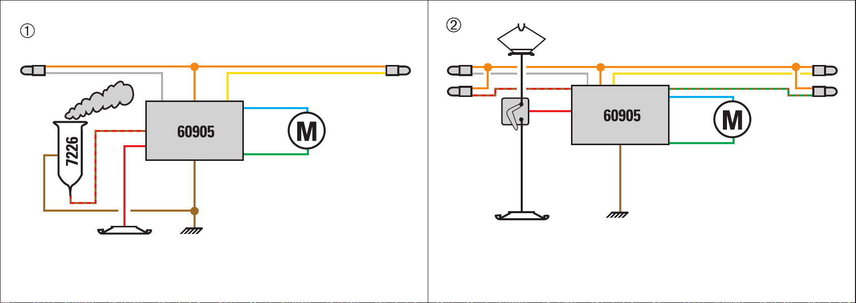
Kabelfarben:
Rot = Fahrstrom Hinleiter
Braun = Rückleiter
Grau = Licht vorne Hinleiter
Gelb = Licht hinten Hinleiter
Blau = Motoranschluss
Grün = Motoranschluss
Orange = Rückleiter Funktionen
Braun/ Rot = Hinleiter Funktion 1
Braun/ Grün = Hinleiter Funktion 2
Hinweis zur Beleuchtung:
An den Funktionsausgängen des Decoders liegt je
nach Umgebungsbedingung eine Gleichspannung
von bis zu 19 Volt an. Angeschlossene Verbraucher
müssen daher für diese Spannung ausgelegt sein.
Leuchtdioden können daher nur mit geeigneten
Vorwiderständen (20 mA: 820 W - 1 kW , 10 mA:
1,8 kW, 2 mA: 8,2 kW - 10 kW) betrieben werden.
Die Polarität der LEDs ist zu beachten. Beim Decoder
60905 wird die fahrtrichtungsabhängige Beleuchtung
nicht über die Polarität der Gleichspannung sondern
über separate Ausgänge erreicht. Daher ist die LEDBeleuchtung vieler Fahrzeuge beim Einbau dieses
Decoders komplett umzubauen!
5
Page 4
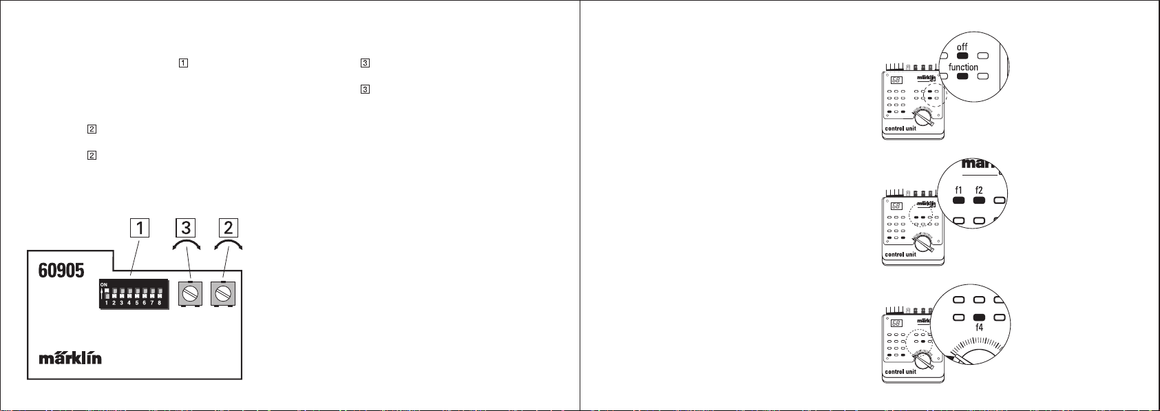
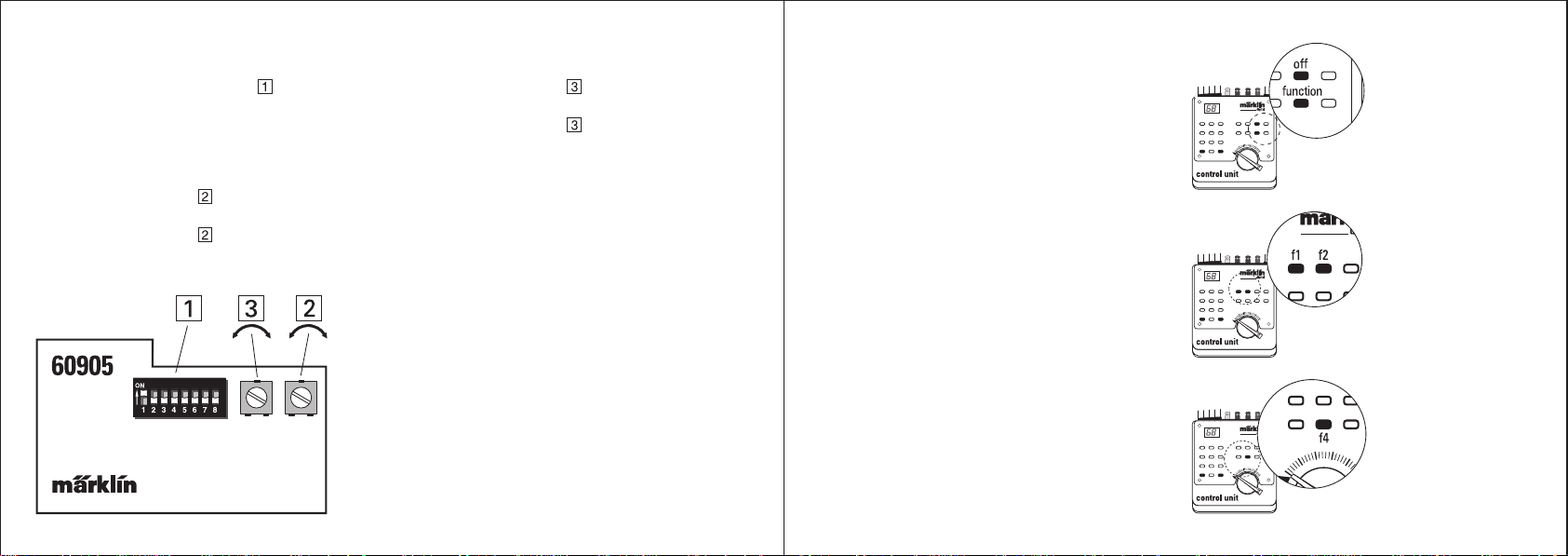
Einstellen der Digitaladresse
Am 8- stelligen Codierschalter wird die Adresse
der Lok eingestellt (=> Tabelle 1).
Einstellen der Höchstgeschwindigkeit:
Einstellen der Anfahr-/ Bremsverzögerung:
Drehen Poti nach rechts = Zunahme
der Anfahr- und Bremsverzögerung
Drehen Poti nach links = Abnahme
der Anfahr- und Bremsverzögerung
Der unter “function” in der technischen Information
angegebene elektrische Verbraucher wird mit der
Taste “function” auf der Control Unit 6021 ein- und
mit der Taste “off” ausgeschaltet.
Drehen Poti
Endgeschwindigkeit
Drehen Poti
Endgeschwindigkeit
nach rechts = höhere
nach links = niedrigere
Schalten der Funktionsausgänge
Als Digital-Zentraleinheit ist nur die Control Unit 6021
verwendbar. Der vierfach Betriebsarten-Schalter auf
der Rückseite der Control Unit muß entweder in der
Stellung UNIVERSAL (Schalter 1, 3 und 4 auf off,
Schalter 2 auf on) oder CONTROL UNIT (Schalter 1,
2 und 3 auf on, Schalter 4 auf off) stehen.
Der unter “f1” (“f2”) in der technischen Information
angegebene elektrische Verbraucher wird durch
Drücken der Taste “f1” (“f2”) auf der Control Unit
6021 eingeschaltet und durch eine weitere Betätigung
der entsprechenden Taste wieder ausgeschaltet.
Durch Einschalten der Funktion “f4” über die Taste
“f4” auf der Control Unit wird die eingestellte Anfahrund Bremsverzögerung auf den minimalen Wert
gesetzt.
76
Page 5

Installation
This product is only designed for installation
authorized Märklin Digital dealers. Please take note
of the complete technical information (page 21).
The 12 month warranty applies to this product only
when it is installed by an authorized Märklin Digital
dealer or repair center.
The 60905 decoder is designed for converting
locomotives with can motors with bell-shaped
armatures. Keeping in mind the maximum continuous
current draw limit of 1.0 amps at the motor output,
this decoder is suitable for H0 and Märklin 1. In
principle this decoder can also be used for other
high quality permanent magnet motors. Very simply
constructed direct current motors can however cause
the destruction of the decoder, despite a nominal
current draw that is below the load limit.
The function outputs (not the motor output!) on the
decoder are protected against short circuits.
Preparing The Locomotive
Before this kit is installed, the consumer must indicate
whether and which auxiliary functions he/she wants
to be connected to the decoder. There are a total
of 3 different functions that can be controlled with
the decoder.
“function” = headlights
“f1” = smoke generator
“f2” = engineer’s cab lighting
Please keep in mind that functions controlled in digital
operation under “function” and “f1” are turned on
constantly in conventional operation with AC power.
Also ask your customers what settings he/she for the
digital address, maximum speed and acceleration/
braking delay.
Maximum current load for the decoder:
motor output: 1,000 milliamps continuous
current, short term load
2,000 milliamps
“function” output: 150 milliamps continuous
current, short term load
250 milliamps
“f1”, “f2” output: 300 milliamps continuous
current, short term load
500 milliamps
Important: The maximum continuous current load
for the entire decoder is 1.2 amps! The critical point
in the current draw for the motor is when the motor
is stalled. You can check this value with the 37100
decoder tester by blocking the driving wheels on the
locomotive.
Checking the Locomotive
Test the model to make sure it is working properly,
before doing the conversion. Make sure that parts
on the motor that can wear out (motor brushes) are
in good working condition.
Important: The noise interference circuits (choke,
condensers, etc.) built into the motor by the locomotive
manufacturer are still required, and for that reason
they must not be removed.
Wire Colors:
red = track power conductor
brown = ground return
gray = hot wire to the front headlight
yellow = hot wire to the rear headlight
blue = motor connection
green = motor connection
orange = ground return for functions
brown/red = hot wire to function 1
brown/green = hot wire to function 2
Information about Lighting:
Depending on the situation, there is a direct current
of up to 19 volts present at each of the function
outputs on the decoder. Users connected to these
outputs must therefore be designed for this voltage.
LEDs can be operated only when suitable protective
resistors are used in the circuits (20 milliamps:
820 Ohms - 1 kilo Ohm, 10 milliamps: 1.8 kilo Ohms,
2 milliamps: 8.2 kilo Ohms - 10 kilo Ohms). Attention
must be paid to the polarity of the LEDs. On the
60905 decoder the changeover of the headlights
with the change in the direction of travel is not
achieved with the polarity of the direct current, rather
it is done with separate outputs. For that reason the
LED lighting circuit must be totally rebuilt on many
locomotives when installing this decoder!
98
Page 6
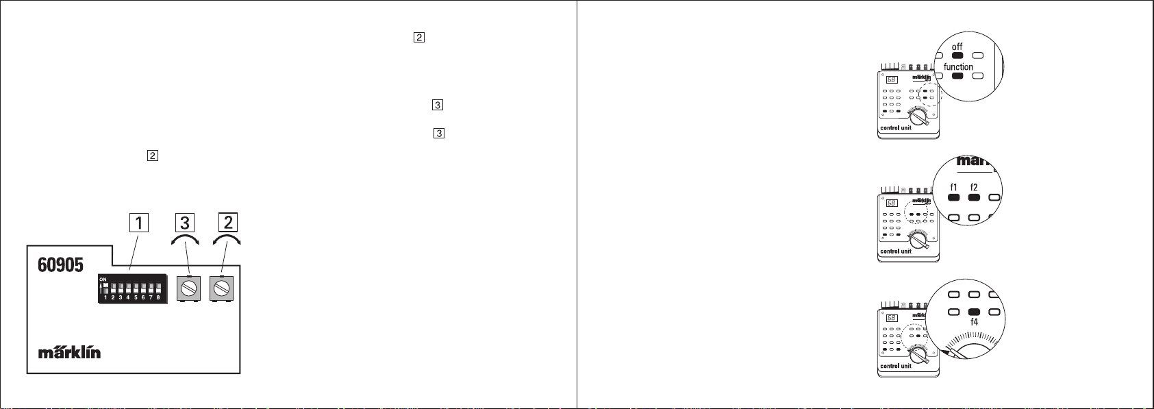
Setting the Digital Address:
The address for the locomotive decoder is set with
the 8 coding switches => Table 1.
The address set during the conversion is on
page 21.
Setting the maximum Speed:
Turn the pot adjustment
end speed.
to the right = higher top
Turn the pot adjustment
speed.
Setting the Acceleration and Braking Delay:
Turning the pot adjustment
the acceleration and braking delay.
Turning the pot adjustment
the acceleration and braking delay.
Turning the Function Outputs On/Off
Only the 6021 Control Unit can be used as a digital
central unit. The four coding switches on the back
of the Control Unit for the operating modes must
either be set at UNIVERSAL (switches 1, 3 and 4 at
off, switch 2 at on) or CONTROL UNIT (switches 1,
2 and 3 at on, switch 4 at off).
to the left = lower top end
to the right: increases
to the left: decreases
The electrical users indicated in the technical
information under “function” are turned on with the
“function” button on the 6021 Control Unit and off
with the “off” button.
The electrical users indicated in the technical
information under “f1” (“f2”) are turned by pressing
the button “f1” (“f2”) on the 6021 Control Unit and off
by pressing the corresponding button a second time.
Turning function “f4” on with the button “f4” on the
Control Unit sets the acceleration and braking delay
to the minimum value.
1110
Page 7

Mode d’emploi
Ce produit est exclusivement destiné a être monté
par un détaillant Märklin Digital agréé. Voir aussi
notre complément d’informations techniques
page 21.
La garantie de 12 mois n’est valable que si le
montage est effectué par un atelier Märklin Digital
agréé.
Le décodeur 60905 est prévu être installé dans les
locomotives équipées d'un moteur à rotor sans fer.
Compte tenu de sa consommation en courant
maximale de 1,0 A, ce module convient pour les
locomotives H0 et 1. En principe, ce décodeur peut
également être installé dans les locomotives équipées
d'un moteur à aimant permanent de bonne qualité.
Mais, en dépit d'une consommation en courant
nominale se situant en dessous de la limite de
charge, les moteurs à courant continu de construction
simplifiée risquent cependant d'être détériorés.
Les sorties pour fonctions (pas les sorties pour
moteur) du décodeur sont protégées contre les
courts-circuits.
Préparation de la locomotive
Avant le montage, il faut d’abord déterminer, en
accord avec vos clients, quelles fonctions doivent
être raccordées. Le kit offre en tout 3 fonctions supplé-
mentaires externes commutables.
Exemple:
«function» = éclairage (feux de signalisation)
«f1» = générateur fumigène
«f2» = éclairage postes de conduite
N’oubliez cependant pas que les appareils consommateurs raccordés en mode Digital aux sorties de
fonction appellées «function» et «f1» sont, en mode
d’exploitation conventionnelle à courant alternatif,
activés en permanence.
Demandez également à vos clients quels réglages
ils désirent pour l’adresse Digital, la vitesse maximale
et la temporisation d’accélération/décélération.
Charges maximales autorisées sur le décodeur:
Sorties moteur: 1000 mA en régime continu,
2000 mA en régime
momentané
Sorties «function»: 150 mA en régime continu,
250 mA en régime
momentané
Sorties «f1», «f2»: 300 mA en régime continu,
500 mA en régime
momentané
Remarque: En régime permanent, le décodeur ne
peut être soumis, toutes sorties confondues, à une
charge supérieure à 1,2 A ! Le point critique de la
consommation en courant se détermine en bloquant
le moteur. En utilisant le testeur de décodeur 37100,
il est possible de vérifier cette valeur critique lors du
blocage des roues motrices sur une voie de test.
Vérification de la locomotive
Vérifiez que le modèle fonctionne sans problème
avant d'effectuer la modification. Vérifiez ensuite le
bon état des pièces d'usure (balais) du moteur.
Remarque: les dispositifs d'antiparasitage installés
par le constructeur sur la locomotive (selfs,
condensateurs, etc.) ne doivent pas être enlevés car
ils sont nécessaires.
Couleur des câbles
Rouge = amenée courant traction
Brun = fil de retour
Gris = amenée courant d’éclairage avant
Jaune = amenée courant d’éclairage arrière
Bleu = connexion moteur
Vert = connexion moteur
Orange = fil de retour fonctions
Brun/rouge = amenée courant fonction 1
Brun/vert = amenée courant fonction 2
Remarque sur les feux de signalisation et
l'éclairage
En fonction des conditions d'exploitation, une tension
continue pouvant atteindre 19 V est appliquée aux
sorties pour fonctions du décodeur. Les appareils
consommateurs de courant connectés doivent par
conséquent être adaptés à une telle tension. En
particulier, les diodes lumineuses doivent être
raccordées en série avec une résistance appropriée
(20 mA: 820W - 1 kW , 10 mA: 1,8kW, 2 mA:
8,2 kW - 10 kW). En outre, il faut veiller à la bonne
polarité des diodes. Avec le décodeur 60905, les
feux de signalisation s'inversant en fonction du sens
de marche ne sont pas alimentés directement par
la tension appliquée à la voie mais via des sorties
1312
Page 8
séparées du décodeur. Par conséquent, sur de
nombreux véhicules, il sera nécessaire de remanier
complètement le câblage des feux en cas
d'installation de ce décodeur !
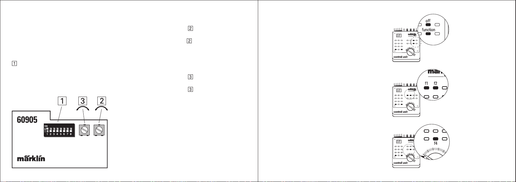
Réglage de l’adresse:
L’adresse se programme sur le «switch» d’encodage
à 8 positions => Tableau 1.
L’adresse programmée lors de la transformation se
trouve page 21.
Réglage de la vitesse maximale:
Tourner le potentiomètre
maxi plus élevée.
Tourner le potentiomètre
maxi moins élevée.
Réglage de la temporisation du démarrage
et du freinage:
Tourner le potentiomètre
augmentation de la temporisation.
Tourner le potentiomètre
diminution de la temporisation.
Commande des fonctions:
Seule la Control Unit 6021 convient comme unité
centrale digitale. Le «switch» programmeur se
trouvant au dos de l’appareil, doit impérativement
se trouver en position UNIVERSAL (interrupteurs 1,
3 et 4 placés sur off, le 2 placé sur on) ou en position
CONTROL UNIT (interrupteurs 1, 2 et 3 placés
sur on, le 4 placé sur off).
vers la droite = vitesse
vers la gauche = vitesse
vers la droite =
vers la gauche =
L’utilisateur électrique complémentaire désigné
comme «fonction» dans le mode d’emploi technique
est activé par la touche «function» de la Control Unit
6021 et désactivé par la touche «off».
L’utilisateur électrique complémentaire désigné
comme «f1» («f2») dans le mode d’emploi technique
est activé par pression de la touche «f1» («f2») de
la Control Unit 6021 est désactivé par une nouvelle
pression de cette touche.
En activant la touche «f4» de la Control Unit, la
temporisation du démarrage et du freinage est
annulée.
1514
Page 9

Inbouwaanwijzing
Dit produkt is alleen bestemd voor inbouw door de
Märklin-digitaal winkelier. Neem de volledige
technische informatie in acht (Pag. 21).
Alleen bij inbouw door de geautoriseerde Märklindigitaal winkelier of het Märklin service centrum is
de Märklin garantie van 12 maanden geldig.
De decoder 60905 is bedoelt om locomotieven met
een klokanker-motor om te bouwen. Als rekening
gehouden wordt met de maximale, continu stroom
van de motoruitgang van 1,0 Amp. kan deze decoder
zowel voor H0, alsmede Märklin spoor 1 modellen
toegepast worden. In principe kan deze decoder
gebruikt worden voor andere hoogwaardige motoren
met permanent magneten. Eenvoudig opgebouwde
gelijkstroom motoren kunnen, ondanks dat de
maximaal opgenomen stroom onder de
belastingsgrens blijft, toch tot het defect raken van
de decoder leiden.
De functie uitgangen (niet de motoruitgang) van de
decoder zijn beveiligd tegen kortsluiting.
Voorbereiding van de locomotief
Voor het inbouwen dient u met de klant af te spreken,
of en welke extra functie aangesloten dient te worden.
De bouwsteen beschikt in totaal 3, extern aan te
sluiten, functies.
Een voorbeeld:
“function” = frontverlichting
“f1” = rookgenerator
“f2” = Verlichting machinistenhuis
Let er daarbij op, dat de in digitaal bedrijf aangesloten
functies opde uitgangen functionen “f1” bij het gebruik
in wisselstroombedrijf continu ingeschakeld zijn.
Vraag uw klant naar de gewenste instelling van het
digitale adres, de maximale snelheid en de optrekafremvertraging.
Belastbaarheid van de decoder:
Motoruitgang: 1000 mA continustroom,
kortstondig 2000 mA.
Uitgang “functie”: 150 mA continustroom,
kortstondig 250 mA.
Uitgang “f1”, “f2” 300 mA continustroom,
kortstondig 500 mA.
Opmerking: de complete decoder mag met niet
meer dan 1,2 A continustroom belast worden! Het
kritieke punt van de stroomopname van de motor is
het blokkeren van de motor. Met de decodertester
37100 heeft u voor de ombouw de mogelijkheid deze
waarde te meten door de aandrijfwielen op het
testspoor te blokkeren.
Loc testen.
Test het model voor de ombouw op de juiste werking.
Controleer de, aan slijtage onderhevige, delen
(koolborstels) van de motor op hun toestand en
vervang deze indien noodzakelijk.
Opmerking: de door de fabrikant van de loc
ingebouwde motor-ontstoringschakeling (spoelen,
condensatoren e.d.) blijven noodzakelijk en mogen
daarom niet verwijderd worden.
Kleuren van de draden:
rood = rijstroom
bruin = rijstroom, retour/massa
grijs = licht voor
geel = licht achter
blauw = motor aansluiting
groen = motor aansluiting
oranje = retour van functies/licht
bruin/rood = extra functie 1
bruin/groen = extra functie 2
Opmerking voor de verlichting:
op de functie uitgangen van de decoder staat,
afhankelijk van invloeden van buitenaf, een
gelijkspanning van maximaal 19 Volt. Aangesloten
gebruikers dienen daarom voor deze spanning
geschikt te zijn. LEDs mogen dan ook alleen via
voorschakelweerstanden (20 mA: 820 Ohm 1 k Ohm, 10 mA: 1,8 k Ohm, 2 mA 8,2 - 10 k Ohm.)
aangesloten worden. Let op de juiste polariteit bij
de LEDs. Bij de decoder 60905 wordt de
rijrichtingsafhankelijke verlichting niet door het
omkeren van de polariteit, maar door twee
gescheiden uitgangen aangestuurd. Daarom moet
bij vele modellen de LED verlichting geheel
omgebouwd worden voor het inbouwen van deze
decoder!
1716
Page 10
Instellen van het digitaal adres
Met de 8-polige codeerschakelaar
van de locomotief ingesteld => tabel 1. Het bij de
ombouw ingestelde adres staat op pagina 21.
Instellen van de maximale snelheid
wordt het adres
Instellen van de optrek- en afremvertraging
Draai de potentiometer
optrek- en afremvertraging
Draai de potentiometer
optrek- en afremvertraging
naar rechts = langere
naar links = kortere
De elektrische verbruiker die in de technische
informatie aangeduid wordt met “functie” wordt op
de Control Unit 6021 ingeschakeld met de toets
“function” en met de toets “off” uitgeschakeld.
Draai de potentiometer
maximale snelheid.
Draai de potentiometer
maximale snelheid.
naar rechts = hogere
naar links = lagere
Schakelen van de functie uitgangen
Als digitaal centrale is alleen de Control Unit 6021
te gebruiken. De viervoudige bedrijfsmodus
schakelaar op de achterzijde van de Control Unit
dient, of in de stand UNIVERSEEL, (schakelaar 1, 3
en 4 op “off” = naar beneden, schakelaar 2 op “on”
= naar boven) of in de stand CONTROL UNIT
(schakelaar 1, 2 en 3 op “on” = naar boven,
schakelaar 4 op “off” = naar beneden) te staan.
De elektrische verbruiker die in de technische
informatie aangeduid wordt met “f1” (“f2”) wordt op
de Control Unit 6021 ingeschakeld met de toets “f1”
(“f2”) en door nogmaals op dezelfde toets te drukken
weer uitgeschakeld.
Door het inschakelen van de functie “f4” met de toets
“f4” op de Control Unit wordt de ingestelde optreken afremvertraging op de minimale waarde gezet.
1918
Page 11
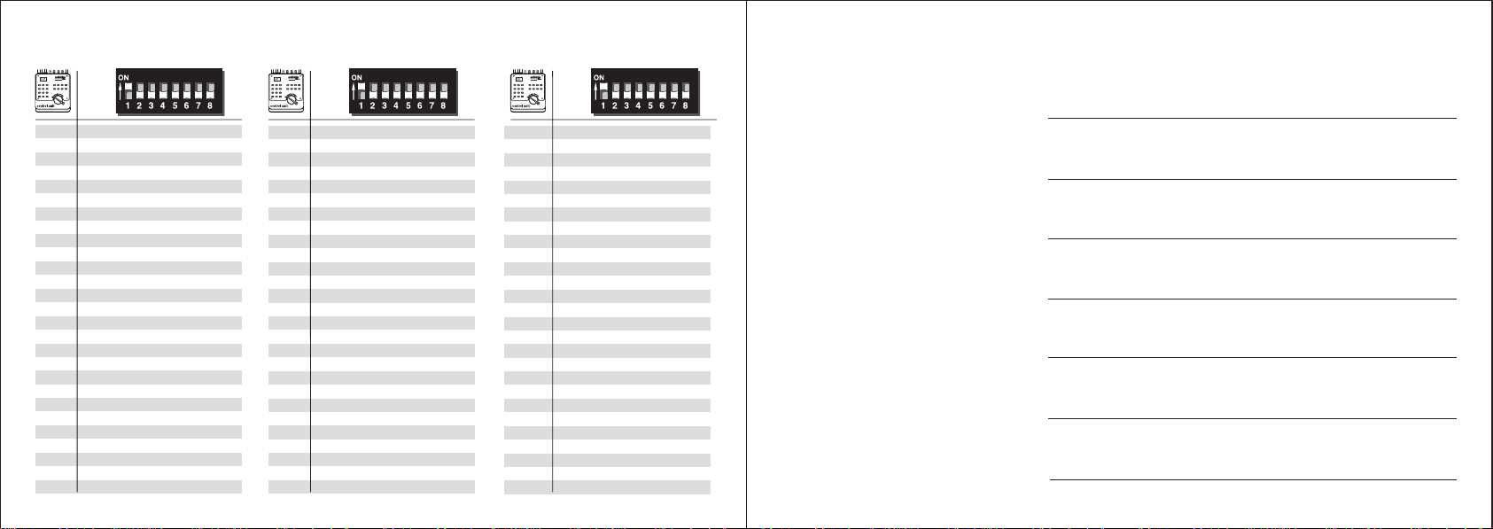
Tabelle 1 (Codiertabelle) – Table 1 (Code table) – Tableau 1 (Tableau d’encodage) – Tabel 1 (codeertabel)
ON ON ON
01 – 23– 5 – 7 –
02 ––3 – 5 – 7 –
03 1 ––45– 7 –
04 – 2 – 45– 7 –
05 –––45– 7 –
06 1 –––5 – 7 –
07 – 2 ––5 – 7 –
08 ––––5 – 7 –
09 1 – 3 ––67–
10 – 23––67–
11 ––3 ––67–
12 1 ––4 – 67–
13 – 2 – 4 – 67–
14 –––4 – 67–
15 1 ––––67–
16 – 2 –––67–
17 –––––67–
18 1 – 3 –––7 –
19 – 23–––7 –
20 ––3 –––7 –
21 1 ––4 ––7 –
22 – 2 – 4 ––7 –
23 –––4 ––7 –
24 1 –––––7 –
25 – 2 ––––7 –
26 ––––––7 –
20
27 1 – 3 – 5 ––8
28 – 23– 5 ––8
29 ––3 – 5 ––8
30 1 ––45––8
31 – 2 – 45––8
32 –––45––8
33 1 –––5 ––8
34 – 2 ––5 ––8
35 ––––5 ––8
36 1 – 3 ––6 – 8
37 – 23––6 – 8
38 ––3 ––6 – 8
39 1 ––4 – 6 – 8
40 – 2 – 4 – 6 – 8
41 –––4 – 6 – 8
42 1 ––––6 – 8
43 – 2 –––6 – 8
44 –––––6 – 8
45 1 – 3 ––––8
46 – 23––––8
47 ––3 ––––8
48 1 ––4 –––8
49 – 2 – 4 –––8
50 –––4 –––8
51 1 ––––––8
52 – 2 –––––8
53 –––––––8
54 1 – 3 – 5 –––
55 – 23– 5 –––
56 ––3 – 5 –––
57 1 ––45–––
58 – 2 – 45–––
59 –––45–––
60 1 –––5 –––
61 – 2 ––5 –––
62 ––––5 –––
63 1 – 3 ––6 ––
64 – 23––6 ––
65 ––3 ––6 ––
66 1 ––4 – 6 ––
67 – 2 – 4 – 6 ––
68 –––4 – 6 ––
69 1 ––––6 ––
70 – 2 –––6 ––
71 –––––6 ––
72 1 – 3 –––––
73 – 23–––––
74 ––3 –––––
75 1 ––4 ––––
76 – 2 – 4 ––––
77 –––4 ––––
78 1 –––––––
79 – 2 ––––––
80 1 – 3 – 5 – 7 –
Technische Information – Technical Information – Information technique – Technische informatie
Artikelnummer der umgebauten Lok
Item number for the converted locomotive
Référence de la locomotive transformée
Artikelnummer van de omgebouwde loc
Fahrgestellnummer
Chassis number
Nº du châssis
Serienummer
Eingestellte Digital-Adresse ab Werk
Digital address set at the factory
Adresse digitale réglée à l’usine
Ingesteld digitaal adres
Angeschlossener Verbraucher an “function”
User connected at “function”
Utilisateur branché sur «function»
Aangesloten verbruiker op “functie”
Angeschlossener Verbraucher an “f1”
User connected at “f1”
Utilisateur branché sur «f1»
Aangesloten verbruiker op “f1”
Angeschlossener Verbraucher an “f2”
User connected at “f2”
Utilisateur branché sur «f2»
Aangesloten verbruiker op “f2”
Datum/Unterschrift Märklin/Fachhändler
Date/Signature of authorized Märklin dealer
Date/Signature du détaillant Märklin agréé
Datum/handtekening Märklin winkelier
21
Page 12
22 23
 Loading...