

Page 1
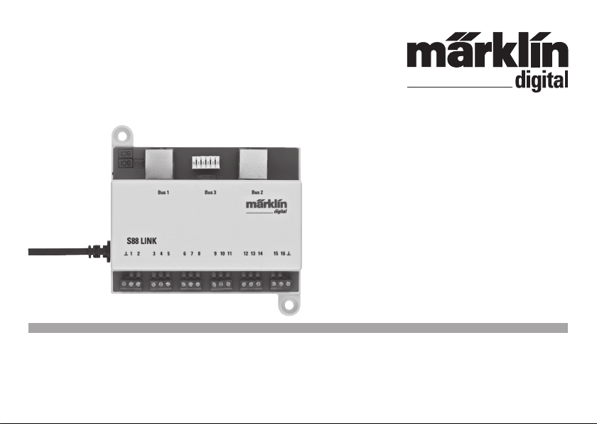
Rückmeldemodul L88
60883
Page 2

Inhaltsverzeichnis:
Seite
Bestimmungsgemäße Verwendung 4
Sicherheitshinweise 4
Wichtige Hinweise 4
Ein- und Ausgänge des Link 88 4
Anschluss 5
Anschluss Übersicht 6
Konfiguration des L88 8
Nutzung als Tasten-Matrix 12
Sommaire :
Page
Utilisation conforme à sa destination 24
Remarques importantes sur la sécurité 24
Information importante 24
Entrées et sorties du Link 88 24
Connectez 25
Vue d’ensemble des branchements 26
Configuration du L88 28
Utilisation comme matrice de touches 32
Table of Contents:
Page
Using the Product as Intended 14
Safety Notes 14
Important Notes 14
Inputs and Outputs for the Link 88 14
Connect 15
Overview of Connections 16
Configuration for the L88 18
Use as a Button Matrix 22
2
Inhoudsopgave :
Pagina
Beoogd gebruik 34
Veiligheidsvoorschriften 34
Belangrijke aanwijzing 34
In- en uitgangen van de Link 88 34
Aansluiten 35
Aansluit overzicht 36
Configuratie van de L88 38
Benutten als drukknoppen-matrix 42
Page 3

Indice de contenido:
Página
Uso correcto 44
Instrucciones de seguridad 44
Notas importantes 44
Entradas y salidas del Link 88 44
Montaje 45
Esquema sinóptico de conexionado 46
Configuración del L88 48
Uso como matriz de teclas 52
Innehållsförteckning:
Sidan
Användning av produkten 64
Säkerhetsanvisningar 64
Viktig information 64
In- och utgångar på Link 88 64
Anslutning 65
Översikt: Anslutninga 66
Konfiguration av L88 68
Användning som knapp-matris 72
Indice del contenuto:
Pagina
Impiego commisurato alla destinazione 54
Avvertenze per la sicurezza 54
Avvertenze importanti 54
Entrate e uscite del Link 88 54
Collegamento 55
Panoramica delle connessioni 56
Configurazione dello L88 58
Utilizzo come matrice di tasti 62
Indholdsfortegnelse:
Side
Hensigtsmæssig anvendelse 74
Sikkerhedshenvisninger 74
Vigtige bemærkninger 74
Ind- og udgange på Link 88 74
Tilslutning 75
Tilslutningsoversigt 76
Konfiguration af L88 78
Anvendelse som tastematrix (kontrolpanel) 82
3
Page 4
Bestimmungsgemäße Verwendung
• Das Rückmeldemodul L88 ist für den Anschluss an die
Central Stationen (CS2) 60213/60214/60215 ab der Software Version 3.8.xx und höher bestimmt.
Anschluss der Rückmeldemodule 6088 (S88)/60880 (S88)/60881
•
(S88 AC) und 60882 (S88 DC) an oben genannte Central Station.
• Das Rückmeldemodul L88 Link ist ein Rückmelder mit 16
Meldekontakten für das Märklin H0-Mittelleitergleis.oder
2L Gleise (Spur 1, Trix H0, Minitrix) mit Reed Kontakten
• Bzw. Anschluss bis zu 64 Taster.
Sicherheitshinweise
• Die Spannungsversorgung des L88 Link erfolgt ausschließlich über das Schaltnetzteil 66361 oder 66201.
• Anschlussarbeiten am Rückmeldemodul L88 Link dürfen
nur im spannungslosen Zustand erfolgen.
• ACHTUNG! Funktionsbedingte scharfe Kanten und Spitzen.
• Das Gehäuse darf nicht geöffnet werden.
• Das Rückmeldemodul L88 Link ist ausschließlich zum
Gebrauch in trockenen Räumen bestimmt.
Wichtige Hinweise
• Die Bedienungsanleitung ist Bestandteil des Produktes
und muss deshalb aufbewahrt sowie bei Weitergabe des
Produktes mitgegeben werden.
• Für Reparaturen wenden Sie sich bitte an Ihren Märklin-
Fachhändler.
• Gewährleistung und Garantie gemäß der beiliegenden
Garantieurkunde.
• Entsorgung: www.maerklin.com/en/imprint.html
4
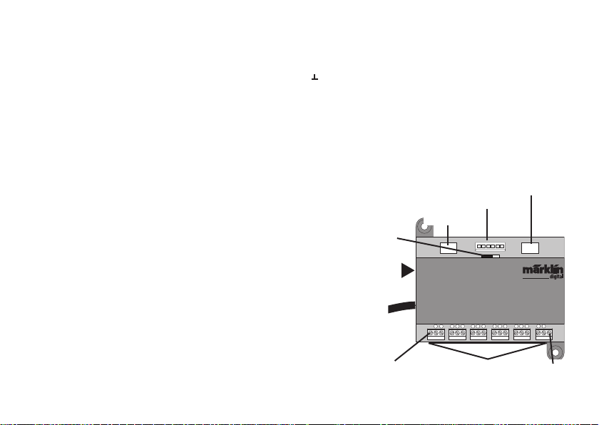
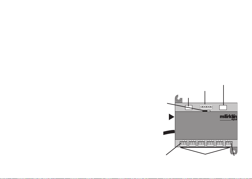
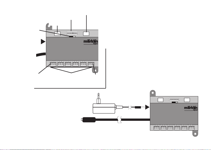
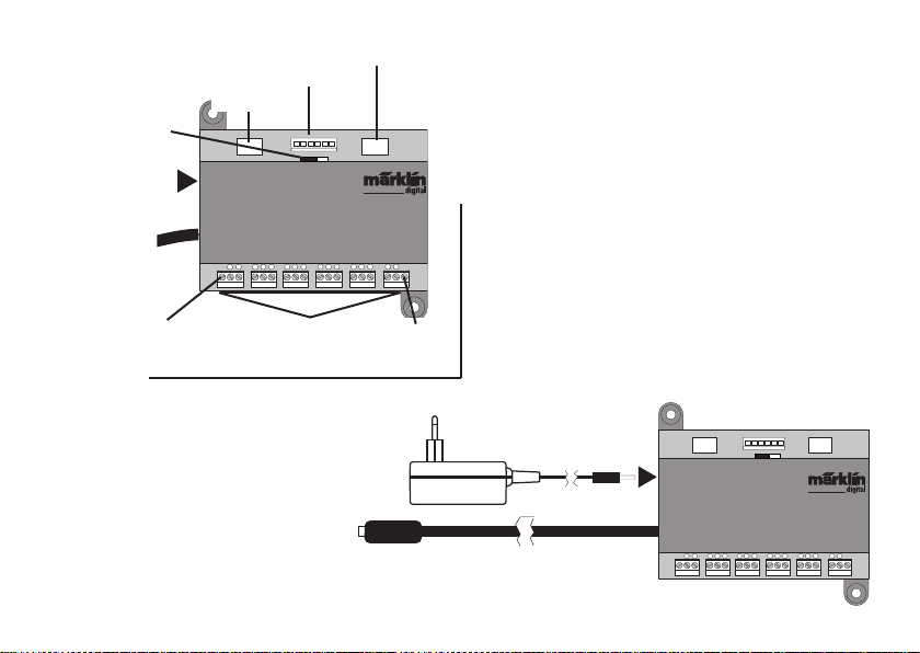
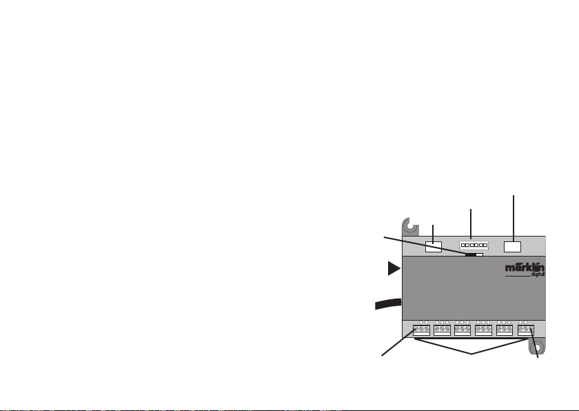
Ein- und Ausgänge des Link 88
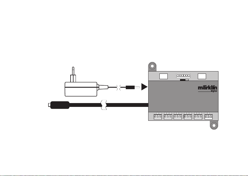
Stromversorgung: Schaltnetzteil 66361 oder 66201.
Anschluss an Central Station / Terminal
Masserückführung (bei Verwendung als Rückmelder)
1-16 Kontaktanschluss (Märklin H0 Mittelleitergleis
oder Taster)
Bus 1 60881 oder 60882
Bus 2 60881 oder 60882
Bus 3 6088 und/oder 60880
Schalter für Stromversorgung der S88 Module mit 5V oder 12V.
Schalter Stromversorgung S88/S88AC/
S88DC
Stromversorgung
60881/60882
60880/6088
5V
Bus 1 Bus 2Bus 3
12V
66361 oder 66201
Central Station /
Terminal
Masserück-
führung
S88 Link
T
1
456
2 3
Gleis oder Taster
7
8
91011
60881/60882
T
15
16
121314
Masserück-
führung
Page 5

Anschluss
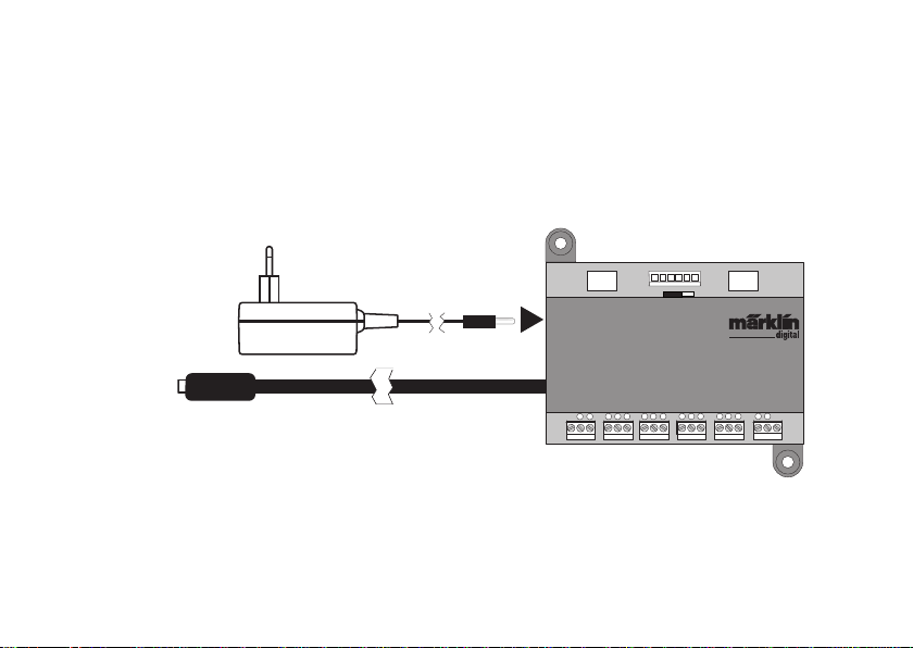
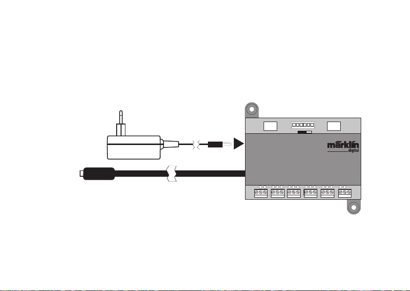
Anschluss an die Central Station
Den Link 88 direkt an den Boosteranschluß der CS2 oder an das Terminal 60125
anschließen, danach die Stromversorgung 66361 oder 66201 einstecken.
5V
Bus 1 Bus 2Bus 3
12V
Central Station /
Terminal
S88 Link
T
1
2 3
456
T
121314
15
16
7
8
91011
5
Page 6
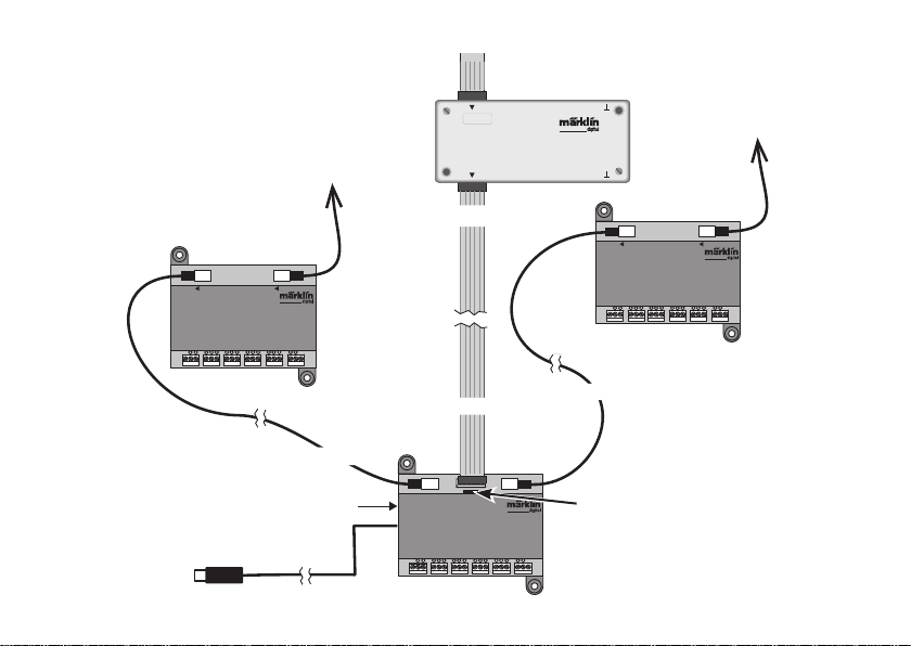
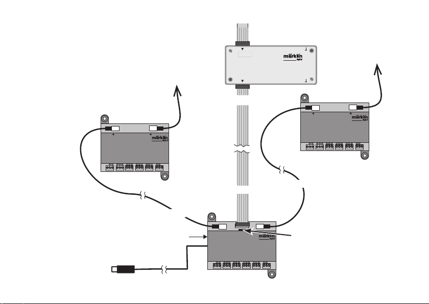
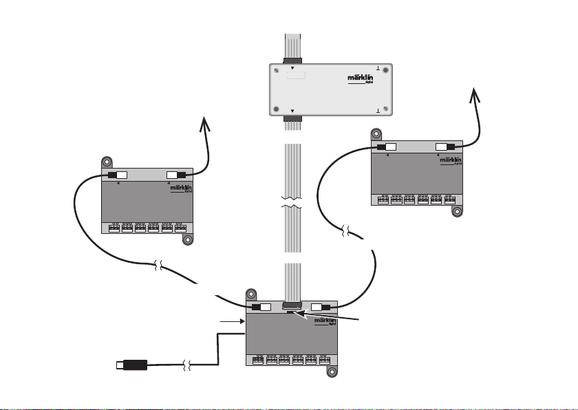
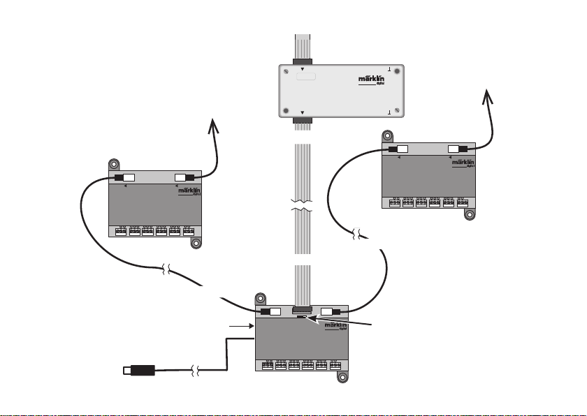
Anschluss Übersicht
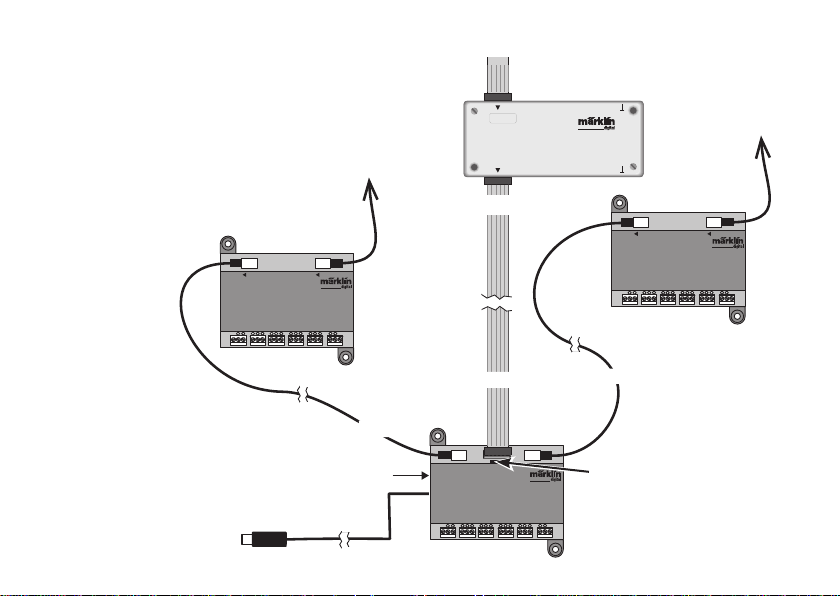
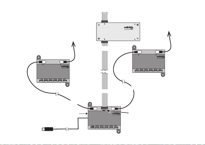
An einen Link 88 können maximal 31 S88 und/oder 62
S88AC/S88DC angeschlossen werden.
87654321
decoder s 88
910111213141516
Max. 31x S88
Ein bestehender Anschluss des S88 an der
Central Station 2 kann beibehalten werden
Bus Bus
Max. 31x
S88 AC oder DC
Bus Bus
S88 AC
T
1
7
6
4
2 3
5
T
15
8
91011
16
121314
Bus 3
S88 DC
T
1
2 3
S88 AC oderDC
Bus 2
7
456
8
Max. 31x
T
16
15
9
11
12
14
10
13
Bus 1
Stromversorgung 66361+60822
S88 Link
T
1
2 3
Bus 1 Bus 2Bus 3
7
456
12V
5V
8
91011
121314
Schalter Stromversorgung
S88/S88AC/S88DC = 5V/12V
(Siehe nächste Seite)
T
15
16
CS2 oder Terminal
6
Page 7
Stromversorgung:
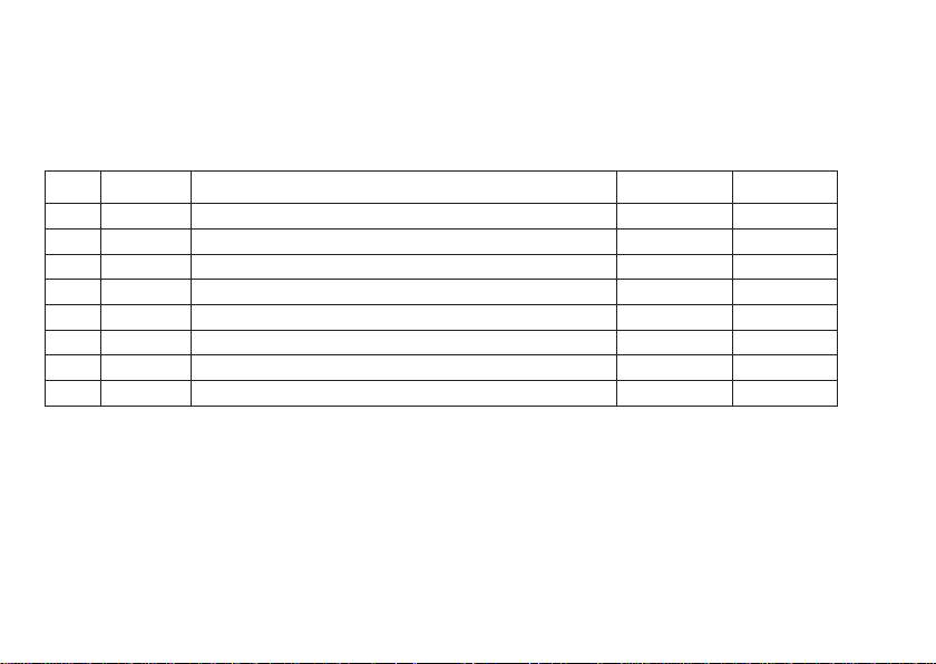
5V im Mischbetrieb von Märklin S88 und S88 AC/DC (wie in Abb. dargestellt), sowie Produkten anderer Anbieter.
12V nur in Verbindung S88 AC/DC. Bei einer Stromversorgung mit 12V wird die Störanfälligkeit verringert.
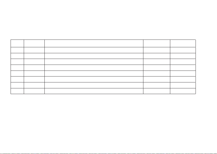
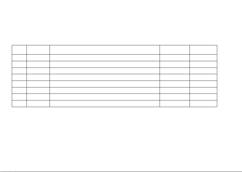
PIN Belegung Pin RJ45
Pin S88 Name Beschreibung Pin RJ45
Farbe
EIA/TIA 568A
1 D ATA Auslesedaten 2 grün
2 GND Masse für Signale und Versorgungsspannung 3 weiss/orange
2 GND 5 weiss/blau
3 CLOCK Taktsignal für die Synchronisation 4 blau
4 PS (LOAD) Lade die Informationen in den Bus 6 orange
5 RESET Zurücksetzen der Eingangsspeicher 7 weiss/braun
6 +5V/+12V Versorgungsspannung für die Rückmeldemodule 1 weiss/grün
— SHIELD Kabelabschirmung, nicht angeschlossen — —
Märklin übernimmt keine Haftung bei gemeinsamer Nutzung von Märklin Produkten und Produkten anderer Anbieter. Wir empfehlen
daher dringend die PIN Belegungen des RJ45 Steckers zu prüfen.
7
Page 8
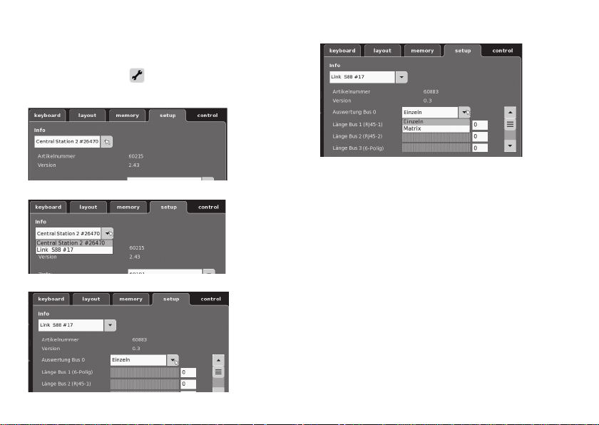
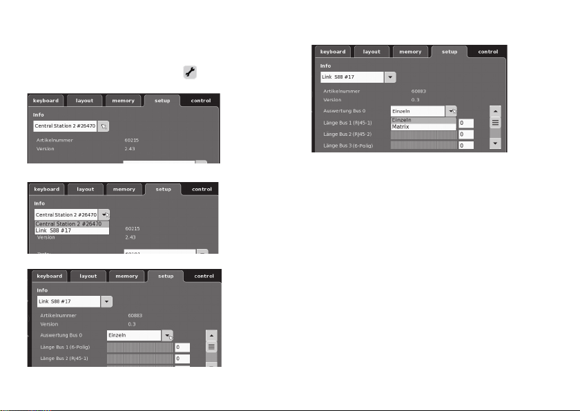
Konfi guration des L88
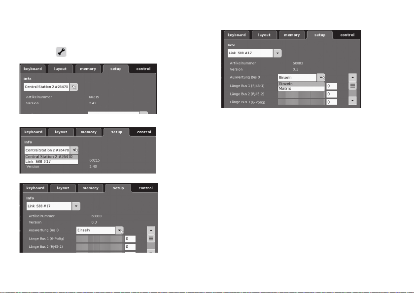
Vor Inbetriebnahme des L88 muss dieser erst konfi guriert
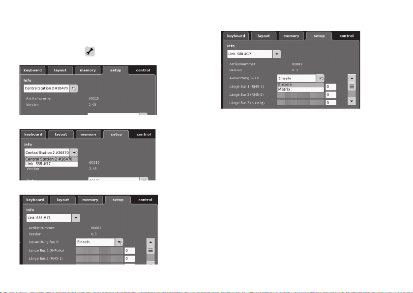
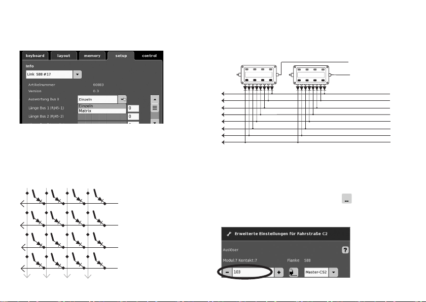
werden. Dazu gehen Sie in der CS auf setup/Info, nun mit
dem Symbol Werkzeug
nachfolgende Abbildungen sind Beispiele:
klappen sie die Info aus
Wählen sie Link S88 #17,
8
in den Konfi gurationsmodus. Alle
jetzt können die einzelnen Daten eingestellt werden.
• Auswertung Bus 0 (direkter Bus des L88),
Einstellung Einzeln = 16 Melde Kontakte
Einstellung Matrix = bis zu 64 Taster
• Länge Bus 1-3
Hier wird eingetragen wieviel S88 an jedem Bus ange-
schlossen sind (max. 31).
• Zykluszeit Bus 1-3
Abfragezyklen der S88 Busse in ms (min 10ms - max. 1000 ms)
eintragen (werkseitig 100ms).
• Bitzeit S88
Einstellen Zyklus der Antwort (werkseitig 167µs)
• Zykluszeit (Link 88) Kontakt 1 - 16
Abfragezyklus der Link Kontakte bei Verwendung als Gleis-
kontakt 1 - 16.
• Zykluszeit Tastastatur
Abfragezyklus bei Verwendung als Tastatur (werkseitig 67ms).
• Spalten (Ausgang) Tastatur
Eintragen der Spalten (max. 8) der Tastatur Matrix
• Zeilen (Eingang) Tastatur
Eintragen der Zeilen (max. 8) der Tastatur Matrix
Page 9
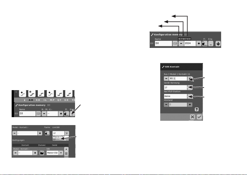
Adressierung der Module:
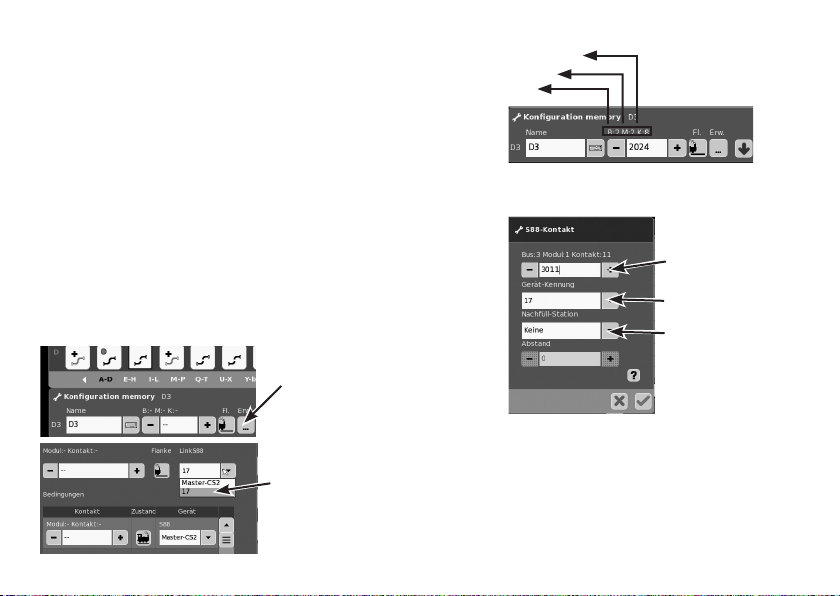
Die Module adressieren sich durch das Einstecken automatisch. Für die Einstellungen in der Central Station finden Sie
nachfolgend die Adresssen.
Kontakte (Gleis): 1-16
Tasteradressen: 101-164
Bus 1: 1001 -1496 (z.B. 1005 = 1. Modul, Kontakt 5)
Bus 2: 2001 - 2496
Bus 3: 3001 - 3496
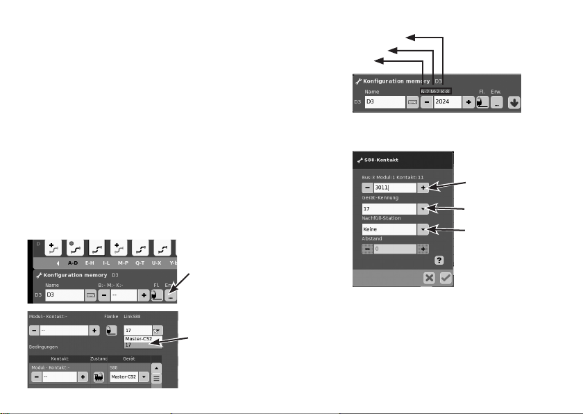
Beispiele von Einstellungen an der Central Station:
Einstellungen an der Central Station:
1. Nutzung als Gleiskontakt:
1.1 Verwendung im Memory (Beispiel):
gehen Sie in Konfigurationsmodus
Über Button Erw. in
die erweiterte Einstellung springen.
Angemeldetes
Gerät auswählen
z.B. Kontakt 8
Modul 2
Bus 2
1.2 Verwendung im Layuot (Beispiel):
gehen Sie in Konfigurationsmodus und definieren den
Kontakt
Adresse (Kontakt)
eingeben
Gerät auswählen
Funktion wählen,
wenn erforderlich
Gerätetausch.
Wird ein Gerätetausch notwendig, kann der neue L88 auf die
bisherige Gerätenummer umgestellt werden. Die Umstellung
erfolgt nach Anmeldung des Link 88 in der CS unter setup Werkzeug - Geräte - bearbeiten. Geben Sie dort dem neuen
Link 88 ihre bisherige Gerätenummer ein und bestätigen
Sie dieses. Danach ist ein Neustart der CS notwendig, nun
funktionieren alle Kontakte wie gewohnt.
9
Page 10
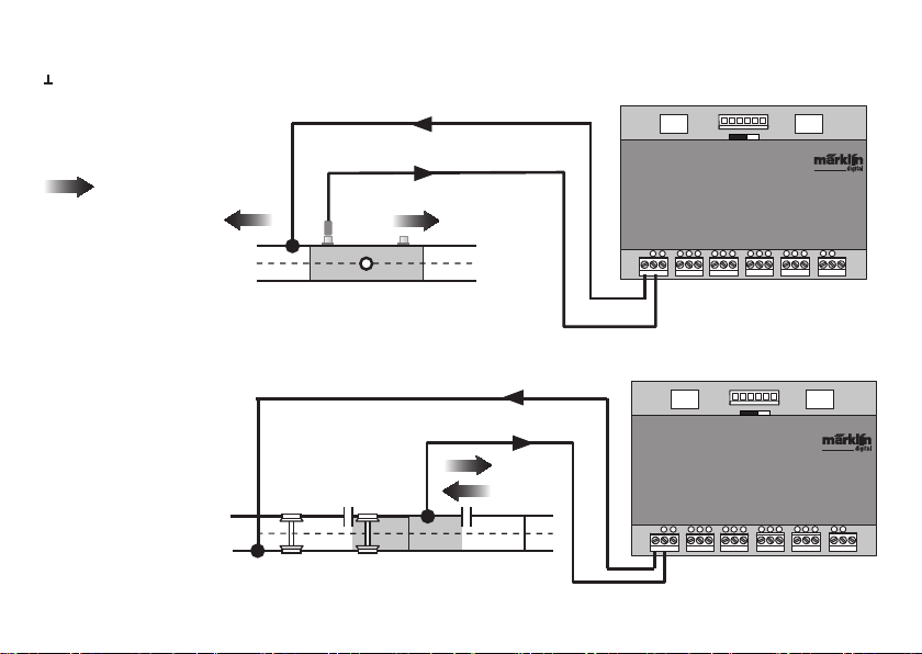
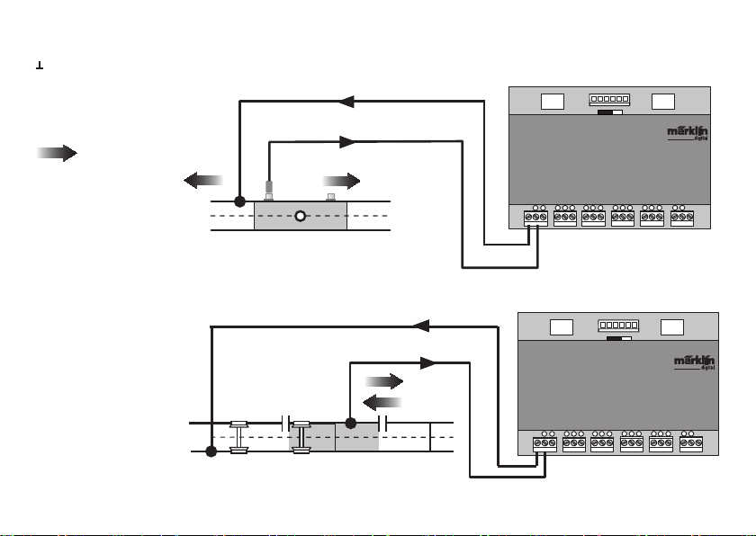
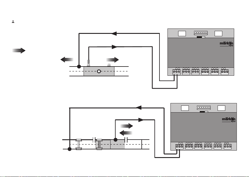
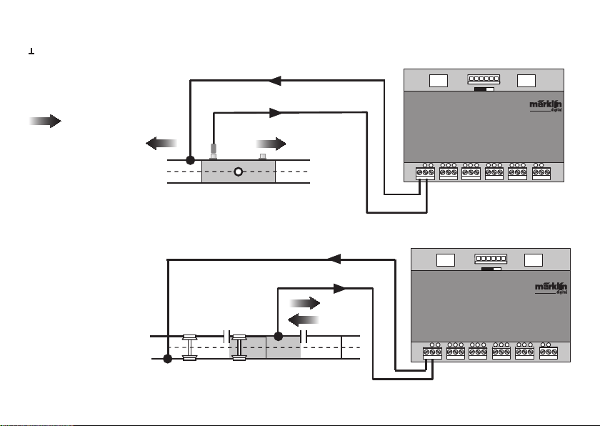
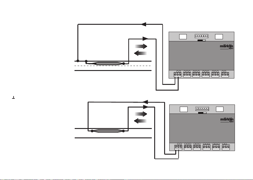
Beispiele für den Anschluss der verschiedenen Melde-Kontakte
Masserückführung für alle Gleis-Kontakte nur 1x erforderlich.
Anschluss an das Märklin
H0-Gleissystem mit dem
Schaltgeis
= Meldende Fahrt-
richtung
Fahrtrichtungsabhängige
Meldung.
Anschluss an das Märklin
H0-Gleissystem mit Kontaktgleisen
Fahrtrichtungsunabhängige Meldung
10
Bus 1 Bus 2Bus 3
S 88 Link
T
1
2 3
S 88 Link
T
1
2 3
5V
7
6
4
8
5
5V
Bus 1 Bus 2Bus 3
7
6
4
8
5
91011
91011
12V
T
15
16
12
14
13
12V
T
15
16
12
14
13
Page 11

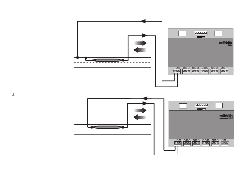
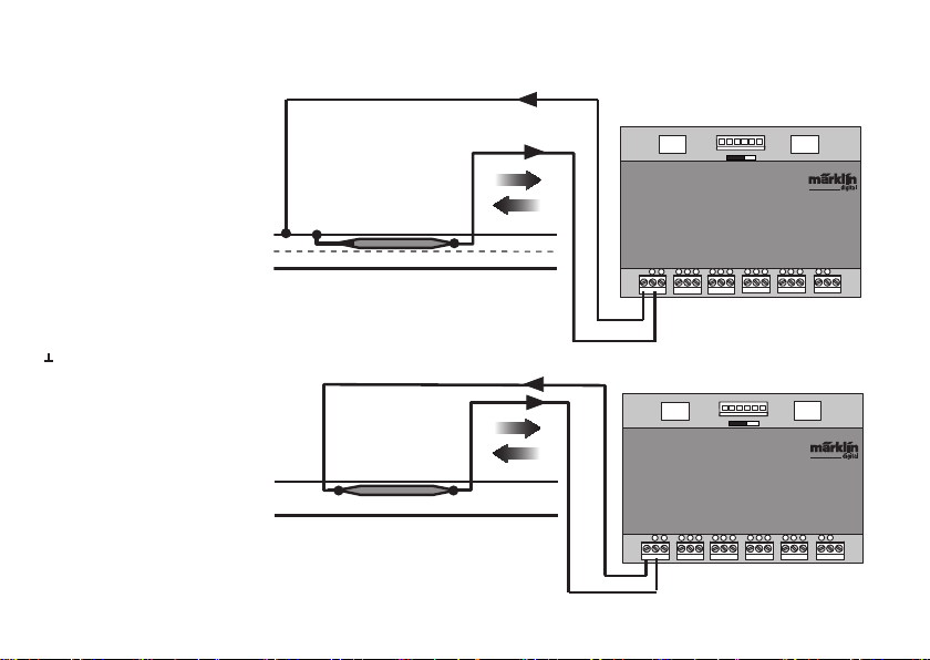
Anschluss an das Märklin
H0-Gleissystem mit Reedkontakt.
Fahrtrichtungsunabhängige
Meldung
Masserückführung ist pro Reed-Kontakt erforderlich
Bus 1 Bus 2Bus 3
S 88 Link
T
1
2 3
12V
5V
7
6
4
8
91011
5
T
15
16
12
14
13
Anschluss an Zweileiter-Gleissysteme, unabhängig von der
Spurgröße nur mit Reedkontakt.
Fahrtrichtungsunabhängige
Meldung
Bus 1 Bus 2Bus 3
S 88 Link
T
1
2 3
12V
5V
7
6
4
8
91011
5
T
15
16
12
14
13
11
Page 12
72720 / 72729 / 7272
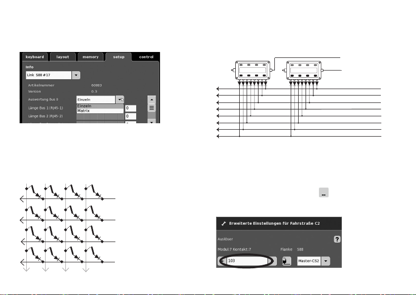
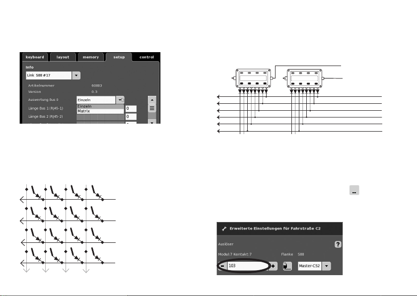
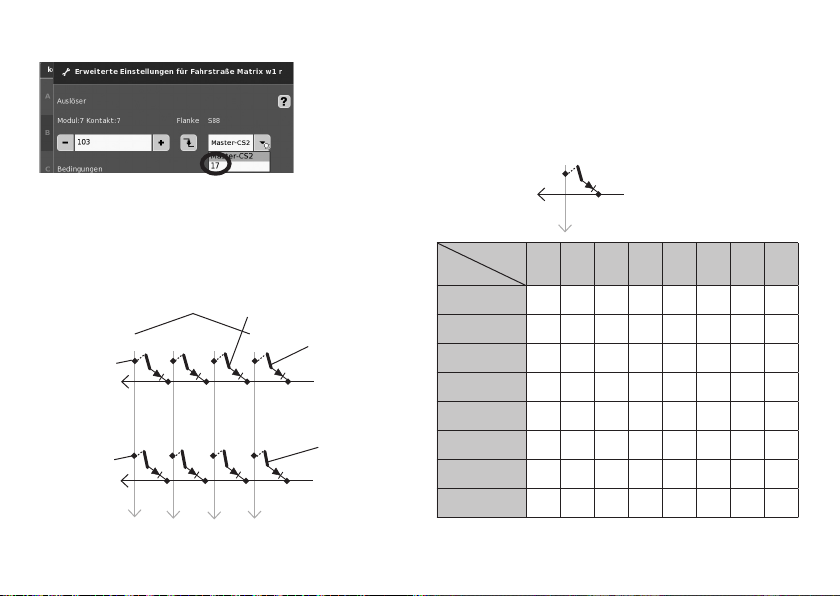
Nutzung als Tasten-Matrix (Stellpult):
Wollen Sie den L88 für eine Tasten-Matrix verwenden, dann
müssen folgende Einstellung vorgenommen werden.
Durch die Einstellung Matrix können max. 64 Taster (32 Magnetartikel oder 64 Fahrstraßen) unterstützt werden. Für den
Aufbau wird pro Taster zusätzlich eine Diode 1N4148 benötigt,
Einbaurichtung beachten.
Kontakt 9-16 (Eingang/Zeilen)
9
12
10
11
Kontakt 1-8 (Ausgang/
1
Spalten)
2
3
4
12
Anschluss Stellpult
Es können max. 8 Stellpulte (Eingang 9 - 16) angeschlossen
werden.
10
Eingang
9
1
2
3
4
5
6
7
8
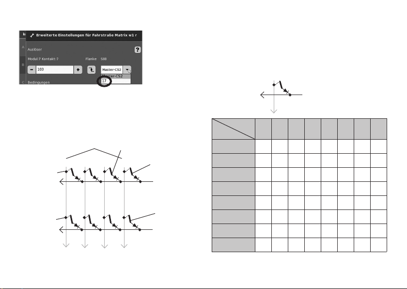
Nun muss jeder Taste eine Fahrstraße zugeordnet werden.
Achten Sie darauf, dass die Fahrstraßen im Memory auf
Automatik-Betrieb eingestellt sind. Die Einstellungen erfolgen
im Konfigurationmodus des Memory (siehe Anleitung der Central
Station).
Die Zuordnung erfolgt über die Taste
Einstellungen für Fahrtstrasse.
in den erweiterten
Geben sie zuerst die Adresse der Taste ein (Tabelle S.13).
Ausgang
Page 13
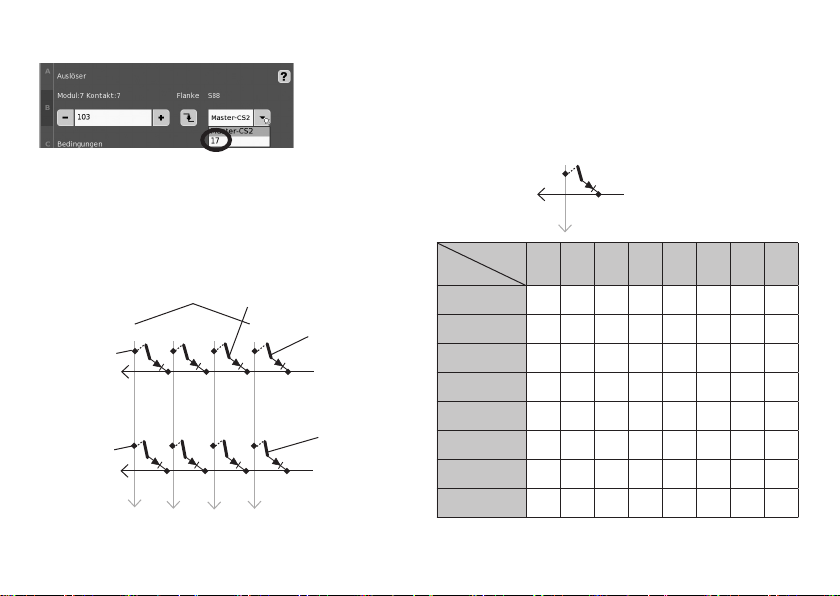
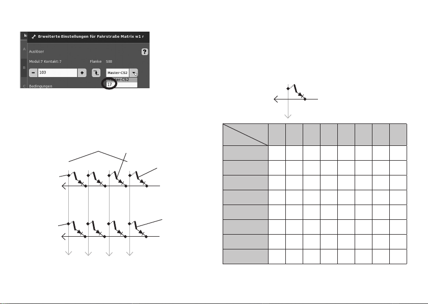
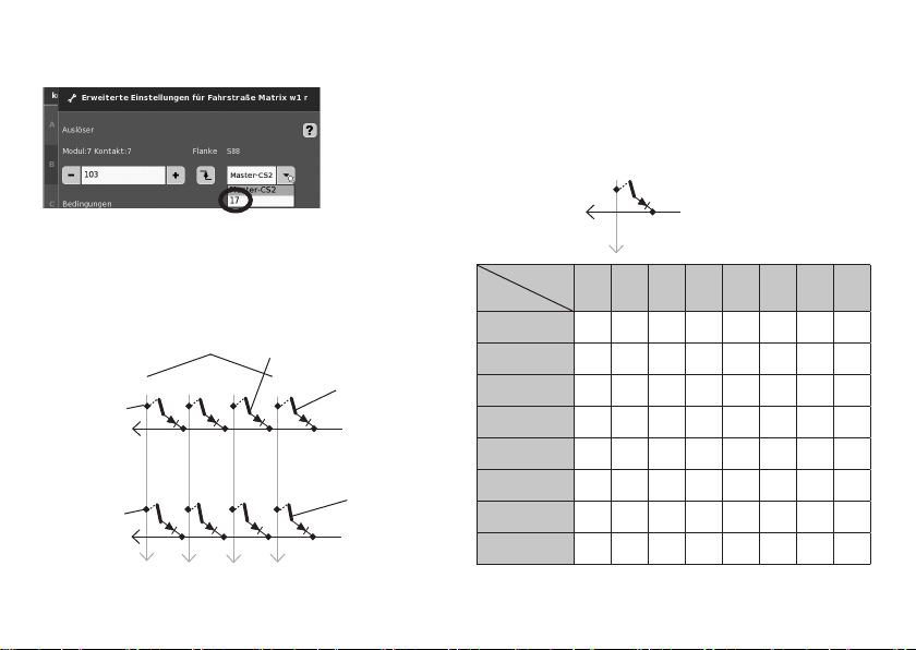
Danach das zugeordnete Gerät (hier 17) eintragen.
Ist alles richtig eingetragen, bestätigen Sie es mit dem
grünen Haken. Auf dem jetzt im Display erscheinenden Bild
mit dem blauen Pfeil zwischen speichern. Danach weitere
Fahrstraßen bearbeiten oder mit dem grünen Haken
bestätigen und beenden.
Adressierung der Tasten (Beispiele)
Taste 25 =125
Taste 26 = 126
Taster
(Eingang)
12
11
18 - 24
25 - 32
10
9 - 17
Taste 9 = 109
9
1 - 8
Taste 1 = 101
1 (Ausgang)
Taste 2 = 102
2 (Ausgang)
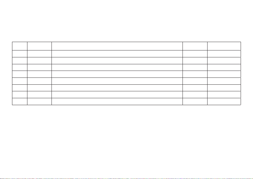
Adresstabelle für die Tasten
Bitte beachten, die Diode muss in Sperrrichtung zum Ausgang
eingebaut sein.
Beispiel Taster 1: Ausgang 9 angeschlossen an Eingang 1 erhält
die Adresse 101.
(Eingang)
Eingang
Ausgang
9
1 (Ausgang)
9 10 11 12 13 14 15 16
1 101 109 117 125 133 141 149 157
2 102 110 118 126 134 142 150 158
3 103 111 119 127 135 143 151 159
4 104 112 120 128 136 144 152 160
5 105 113 121 129 137 145 153 161
6 106 114 122 130 138 146 154 162
7 107 115 123 131 139 147 155 163
8 108 116 124 132 140 148 156 164
13
Page 14
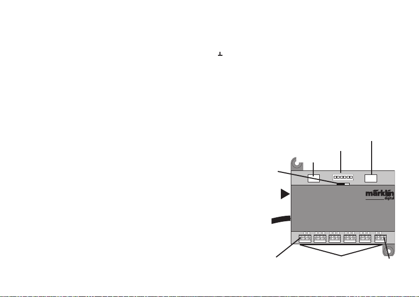
Using the Product as Intended
• The L88 feedback module is designed for connection
to the L88 (60883) and the 60213/60214/60215 Central
Stations (CS2) with Software Version 3.8.xx and higher.
Connections from the 6088/60880/60881 and 60882 feedback
•
modules to the Central Station units mentioned above.
•
The L88 Link feedback module is a position indicator with 16
indicator contacts for Märklin H0 center conductor track or
for 2-rail track (1 Gauge, Trix H0, Minitrix) with reed contacts.
• Or connections to 64 button controllers.
Safety Notes
• The voltage supply for the L88 Link is done only by means
of the 66361/66365 or 66201 switched mode power pack.
• Connections to the L88 Link feedback module may only be
done with no voltage present.
• WARNING! Sharp edges and points required for operation.
• The housing must not be opened.
• The L88 Link feedback module is designed only for use in
dry areas.
Important Notes
• The operating instructions are a component part of the
product and must therefore be kept in a safe place as
well as included with the product, if the latter is given to
someone else.
• Please see your authorized Märklin dealer for repairs
• The warranty card included with this product species
the warranty conditions.
• Disposing: www.maerklin.com/en/imprint.html
14
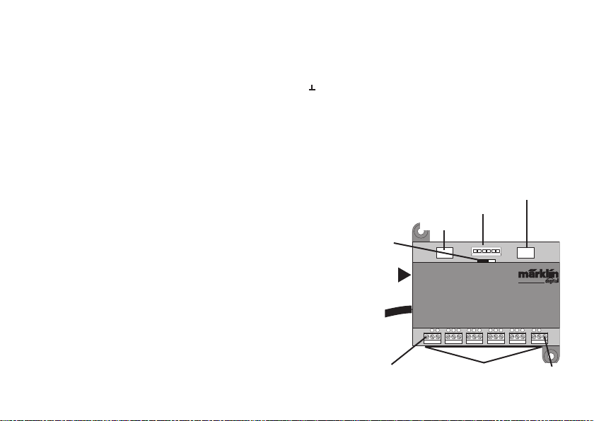
Inputs and Outputs for the Link 88
Current supply: 66361/66365 or 66201 switched mode power pack.
Connections to the Central Station / Terminal
Ground return (when used as a position indicator)
1-16 Contact connections (Märklin H0 center conductor
track or button controllers)
Bus 1 60881 or 60882
Bus 2 60881 or 60882
Bus 3 6088 and/or 60880
Switches for current supply to the S88 Module with 5 volts
or 12 volts.
60881/60882
Switches for current
supply
60881/60882
60880/6088
S88/S88AC/ S88DC
Current supply
Bus 1 Bus 2Bus 3
12V
5V
66361/66365 or
66201
Central Station /
Terminal
Ground Return
S88 Link
T
1
456
2 3
Track or Button
7
8
91011
121314
Controller
T
15
16
Ground
Return
Page 15
Connect
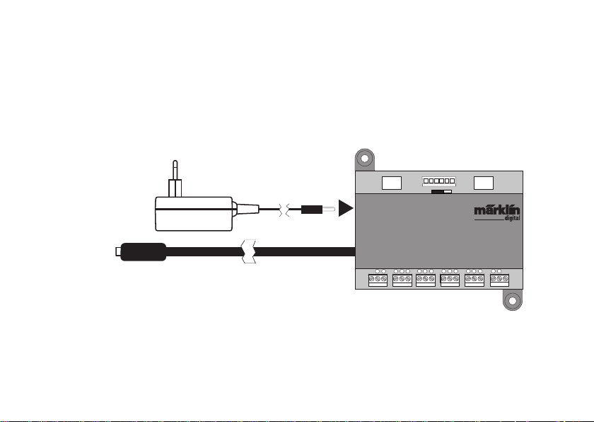
Connections to the Central Station
Connect the Link 88 directly to the Booster connection on the CS2 or to the 60125
Terminal. After that plug in the 66361/66365 or 66201 power supply.
5V
Bus 1 Bus 2Bus 3
12V
Central Station /
Terminal
S88 Link
T
1
2 3
456
T
121314
15
16
7
8
91011
15
Page 16
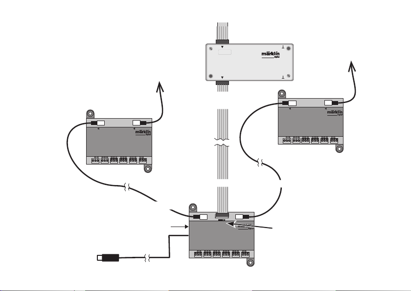
Overview of Connections
A maximum of 31 S88 units and/or 62 S88AC/S88DC
units can be connected to a Link 88.
87654321
decoder s 88
910111213141516
Maximum
31 x S88
An existing connection from the S88 to the
Central Station 2 can be kept.
Bus Bus
16
S88 AC
T
Maximum 31 x
S88 AC or DC
Current supply 66361+ 60822
US only: 66365
CS2 or Terminal
Bus Bus
1
7
6
4
8
2 3
91011
5
S88 DC
T
1
7
456
2 3
T
15
16
121314
T
16
15
8
9
11
12
14
10
13
Maximum 31 x
S88 AC or DC
Bus 3
Bus 2
Bus 1
12V
5V
Bus 1 Bus 2Bus 3
Switches for current supply
S88/S88AC/ S88DC = 5V/12V
S88 Link
T
1
7
456
2 3
15
8
91011
16
121314
(see next page)
T
Page 17
Current Supply:
5volts in mixed operation of S88 and S88 AC/DC Märklin products (as shown in the illustration), as well as products of other
makes.
12 volts only in conjunction with the S88 AC/DC. The susceptibility to interruptions is reduced with a 12 volt power supply.
PIN Assignment for the RJ45 Plug
S88 Pin Name Description PIN RJ45
Color
EIA/TIA 568A
1 D ATA Readout Data 2 green
2 GND Ground for signals and voltage supply 3 white/ orange
2 GND 5 white/blue
3 CLOCK Clock signal for the synchronization 4 blue
4 PS (LOAD) Load the data into the bus 6 orange
5 RESET Reset the input memory 7 white/brown
6 +5V/+12V Voltage supply for the feedback module 1 white/green
— SHIELD Cable shield, not connected — —
Märklin assumes no liability for joint use of Märklin products and products of other makes.
We therefore urgently recommend that you check the PIN assignments of the RJ45 plug you may be using.
17
Page 18
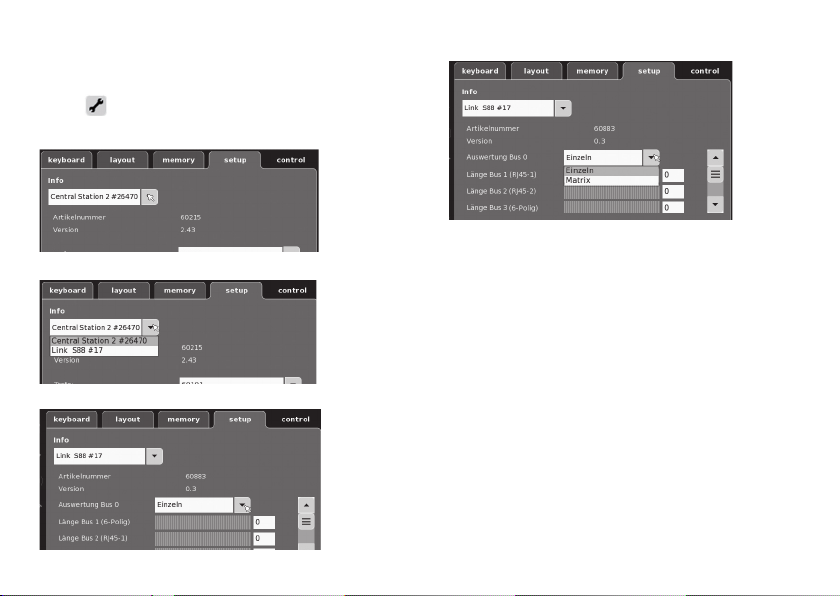
Confi guration for the L88
The L88 must fi rst be confi gured before using it for the fi rst
To do this go into the CS to setup/Info and with the tool
time.
symbol
images are examples:
Open up Info
Select Link S88 #17.
18
go into the confi guration mode. All of the following
Now the individual data can be set..
• Evaluation of Bus 0 (direct bus for the L88),
Setting for individual units = 16 indicator contacts
Setting for matrix = up to 64 button controllers
• Length of Bus 1-3
Here you enter how many S88 units are connected to
each bus (max. 31).
• Cycle period for Bus 1-3
Enter query cycles for the S88 busses in milliseconds (ms)
(min 10 ms - max. 1000 msm, factory setting 100 ms).
• Bit time for the S88
Set the cycle for the answer (factory setting 167 µs)
• Cycle period for (Link 88) Contacts 1 - 16
Query cycles for the Link contacts when used as track
contacts 1 - 16.
• Cycle period for keyboard
Query cycle when used as a keyboard (factory setting 67 ms).
• Columns for the keyboard
Entering the columns (max. 8) for the keyboard matrix
• Rows for the keyboard
Entering the rows (max. 8) for the keyboard matrix
Page 19
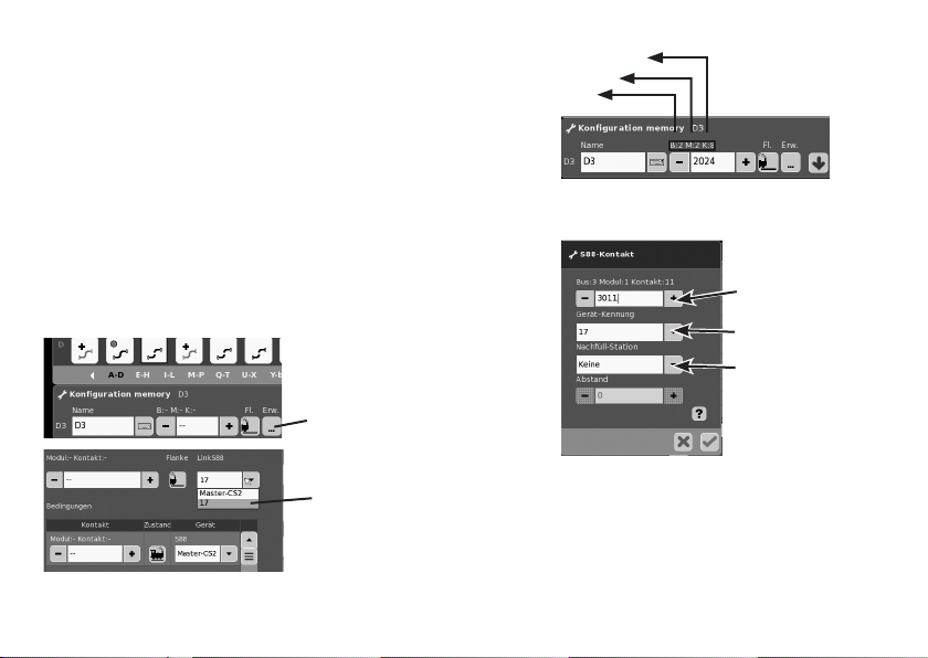
Addresses for the Module:
The module automatically get an address when it is plugged
in. You will find below the addresses for settings in the
Central Station.
Contacts (track): 1-16
Button controller addresses: 101-164
Bus 1: 1001 -1496 (ex. 1005 = 1st module, Contact 5)
Bus 2: 2001 - 2496
Bus 3: 3001 - 3496
Examples of Settings on the Central Station:
Settings on the Central Station:
1. Use as a track contact:
1.1 Use in the Memory (example)
Go into the Configuration mode
Jump over Button
to the advanced
setting.
Select a registered
device
e.g. Contact 8
Modul 2
Bus 2
1.2 Use in the Layout (example)
Go into the Configuration mode and define the contact
Enter address
(contact)
Select device
Select function, if
necessary
Swapping Devices.
If a device swap becomes necessary, the new L88 can be
switched to the previous device number. The switch takes
place after the Link S88 registers in the CS at setup –Tool
–Devices - edit. Enter the new Link S88 there with the
previous device number and confirm this number. After that,
the CS needs to be rebooted. All of the contacts will function
as usual.
19
Page 20
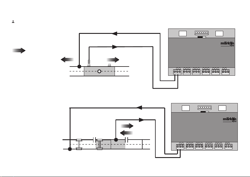
Sample Connections for the Different Feedback Contacts
Only one ground return is required for all track contacts.
Connections to the Märklin
H0 track system with the
Circuit Track
= Direction of tra-
vel feeding back
Feedback is dependent on
the direction of travel
Connections to the Märklin
H0 track system with
Contact Tracks
Feedback is independent
of the direction of travel
20
Bus 1 Bus 2Bus 3
S 88 Link
T
1
2 3
S 88 Link
T
1
2 3
5V
7
6
4
8
5
5V
Bus 1 Bus 2Bus 3
7
6
4
8
5
91011
91011
12V
T
15
16
12
14
13
12V
T
15
16
12
14
13
Page 21
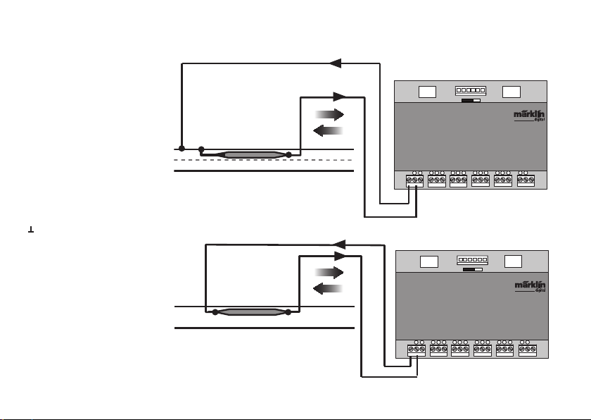
Connections to the Märklin H0
track system with Reed Switches
Feedback is independent of the
direction of travel
Ground return is required per reed switch
Connections to two-rail track systems, independent of the gauge
only with Reed Switches.
Feedback is independent of the
direction of travel
Bus 1 Bus 2Bus 3
S 88 Link
T
1
2 3
S 88 Link
T
1
2 3
5V
7
6
4
8
5
5V
Bus 1 Bus 2Bus 3
7
6
4
8
5
91011
91011
12V
T
15
16
12
14
13
12V
T
15
16
12
14
13
21
Page 22
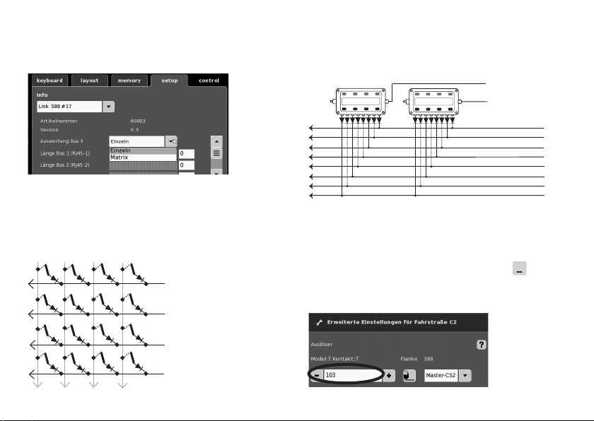
72720 / 72729 / 7272
Use as a Button Matrix (Control Box):
If you want to use the L88 for a button matrix, then the
following setting must be done.
A maximum of 64 button controllers (32 solenoid devices or
64 routes) can be supported by the setting Matrix. A 1N4148
diode per button is required for the setup. Pay attention to
the installation direction.
Contact 9-16 (input) line
9
12
10
11
1
Contact 1-8 (output) Column
2
3
4
22
Connections for a Control Box
A maximum of 8 control boxes (Inputs 9 - 16) can be connected.
10
Input
9
1
2
3
4
5
6
7
8
Now every button must be assigned to a route. Make
sure, that the routes in the Memory are set for automatic
operation.
The settings are done in the configuration mode for the
Memory (see instructions for the Central Station).
The assignment is done by means of the button
advanced settings for a route.
in the
You first enter the address for the button (see table page 23).
Output
Page 23
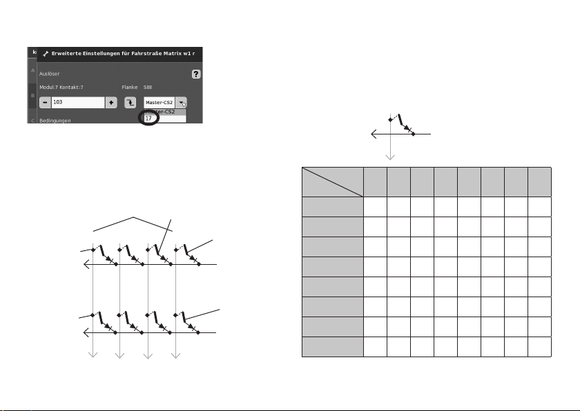
After that enter the assigned device (here 17).
Address Table for the Buttons
Please note, the diode must be installed in the blocking direction
at the output.
Example Button 1: 9 output connected to input 1 is replaced
by the address. 101.
(Input)
9
If everything has been entered correctly, confirm it with the
green check mark. Store in memory along the way with the
blue arrow on the display now appearing in the image. After
that edit or process other routes or confirm with the green
check mark and end the process.
Addresses the button (Example)
Button 25 =125
Button 26 = 126
Taster
(Input)
12
11
18 - 24
25 - 32
10
9 - 17
Button 9 = 109
9
1 - 8
Button1 = 101
1 (Output)
Button 2 = 102
2 (Output)
1 (Output)
Input
Output
9 10 11 12 13 14 15 16
1 101 109 117 125 133 141 149 157
2 102 110 118 126 134 142 150 158
3 103 111 119 127 135 143 151 159
4 104 112 120 128 136 144 152 160
5 105 113 121 129 137 145 153 161
6 106 114 122 130 138 146 154 162
7 107 115 123 131 139 147 155 163
8 108 116 124 132 140 148 156 164
23
Page 24
Utilisation conforme à sa destination
• Le module de rétrosignalisation L88 DC est conçu pour être
branché aux Central Stations (CS2) 60213/60214/60215 à
partir de la version logicielle 3.8.xx et plus.
•
Branchement des modules de rétrosignalisation 6088/60880/
60881 et 60882 à la Central Station mentionnée ci-dessus.
• Le module de rétrosignalisation L88 Link est un module
disposant de 16 contacts de signalisation pour la voie à
conducteur central H0 de Märklin ou les voies 2L (piste 1,
Trix H0, Minitrix) avec des contacts Reed
• Ou branchement de max. 64 contacts.
Remarques importantes sur la sécurité
• L‘alimentation en tension du L88 Link se fait exclusivement
par le biais d‘une alimentation de coupure 66361 ou 66201.
• N‘effectuez les travaux de branchement sur le module de
rétrosignalisation que lorsque le L88 Link est hors tension.
• ATTENTION! Pointes et bords coupants lors du fonction-
nement du produit..
• Le boîtier ne doit pas être ouvert.
• Le module de rétrosignalisation L88 Link ne doit être
utilisé que dans des pièces sèches.
Information importante
• La notice d‘utilisation fait partie intégrante du produit ;
elle doit donc être conservée et, le cas échéant, transmi-
se avec le produit.
• Pour toute réparation adressez-vous à votre détaillant-
spécialisé Märklin.
• Garantie légale et garantie contractuelle conformément
au certificat de garantie ci-joint.
• Elimination : www.maerklin.com/en/imprint.html
24
Entrées et sorties du Link 88
Alimentation électrique : Alimentation de coupure 66361 ou
66201.
Branchement à la Central Station / au Terminal
Retour par la terre (pour une utilisation en tant que rétro-
signalisation)
1-16 branchements de contact (voie à conducteur
central H0 de Märklin ou touche)
Bus 1 60881 ou 60882
Bus 2 60881 ou 60882
Bus 3 6088 et/ou 60880
Interrupteur pour alimentation électrique des modules
S88 à 5 V ou 12 V.
Interrupteur pour
alimentation électrique S88/S88AC/
60881/60882
60880/6088
S88DC
Alimentation
Bus 1 Bus 2Bus 3
électrique 66361
ou 66201.
Central Station /
Terminal
Retour par la
terre
S88 Link
T
1
456
2 3
Voie ou touche
7
5V
8
12V
91011
60881/60882
T
15
16
121314
Retour par
la terre
Page 25
Connectez
Branchement à la Central Station
Branchez le Link 88 directement sur la prise booster du CS2 ou au terminal
60125, puis branchez la prise électrique 66361 ou 66201.
5V
Bus 1 Bus 2Bus 3
12V
Central Station /
Terminal
S88 Link
T
1
2 3
456
T
121314
15
16
7
8
91011
25
Page 26
Vue d’ensemble des branchements
Vous pouvez brancher au maximum 31 S88 et/ou 62
S88AC/S88DC au Link 88.
87654321
decoder s 88
910111213141516
Max. 31x S88
Une connexion existante du S 88 à la Central
Station 2 peut être conservée.
Bus Bus
Max. 31x
S88 AC ou DC
CS2 ou Terminal
26
Bus Bus
S88 AC
T
1
7
6
4
2 3
5
T
15
8
91011
16
121314
Bus 1
Alimentation électrique 66361+60822
S88 Link
T
1
2 3
Bus 3
Bus 1 Bus 2Bus 3
456
S88 DC
T
1
7
456
2 3
T
16
15
8
9
11
12
14
10
13
Max. 31x
Bus 2
12V
5V
Interrupteur pour alimentation élec-
S88 AC ou DC
trique S88/S88AC/S88DC = 5V/12V
(voir la page suivante)
7
T
15
8
91011
16
121314
Page 27
Alimentation en courant :
5V en exploitation mixte de produits Märklin S88 et S88 CA/CC (comme représenté), ainsi que de produits d’autres fournisseurs.
12V uniquement en liaison avec S88 CA/CC. Une alimentation en courant de 12 V permet de réduire la sensibilité aux interférences.
Affectation PIN du connecteur RJ45
PIN S88 Nom Description PIN RJ45
Couleur
EIA/TIA 568A
1 D ATA Données extraites 2 vert
2 GND Masse pour signaux et tension d’alimentation 3 blanc/orange
2 GND 5 blanc/bleu
3 CLOCK Signal d’horloge pour la synchronisation 4 bleu
4 PS (LOAD) Charger les informations dans le bus 6 orange
5 RESET Réinitialisation de la mémoire initiale 7 blanc/marron
6 +5V/+12V Tension d’alimentation pour les modules rétrosignalisation 1 blanc/vert
— SHIELD Blindage câble, non raccordé — —
Märklin n’assume aucune responsabilité dans le cas où des produits Märklin seraient utilisés avec des produits d’autres
marques. Nous recommandons donc vivement de vérifier les affectations PIN de la connexion RJ45 concernée.
27
Page 28
Confi guration du L88
Vous devez confi gurer le L88 avant la mise en service. Pour
cela, allez dans le CS sur setup/Info, puis appuyez sur
l’icône outil
les illustrations suivantes ne sont fournies qu’à titre
pour ouvrir le mode confi guration. Toutes
Agrandissez la fenêtre Info
indicatif :
28
Sélectionnez Link S88 #17,
pour confi gurer les différentes données.
• Évaluation Bus 0 (Bus direct du L88),
Con guration individuelle = 16 contacts de signalisation
Con guration matrice = jusqu‘à 64 palpeurs
• Longueur Bus 1-3
Saisissez ici le nombre de S88 connectés à chaque bus
(max. 31)
• Durée de cycle bus 1-3
Saisissez les cycles d’interrogation des bus S88 en ms
(min 10ms - max. 1000 ms) (confi guration d’usine 100ms).
• Temps de bits S88
Confi guration du cycle de réponse (confi guration d’usine
167µs)
• Durée de cycle (Link 88) contacts 1 - 16
Cycle d’interrogation des contacts du Link pour une
utilisation comme contact de voie 1-16
• Durée de cycle clavier
Cycle d’interrogation pour une utilisation comme clavier
Page 29

(configuration d’usine 67 ms).
• Colonnes Clavier
Saisie des colonnes (max. 8) du clavier Matrice
• Lignes clavier
Saisie des lignes (max. 8) du clavier Matrice
Adressage des modules :
Les modules s’adressent automatiquement dès le branchement. Vous trouverez ci-dessous les adresses pour la
configuration de la Central Station.
Contacts (voies) : 1-16
Adresses des touches : 101-164
Bus 1 : 1001 -1496 (par ex. 1005 = 1. Module, contact 5)
Bus 2 : 2001 - 2496
Bus 3 : 3001 - 3496
Exemples de configuration de la Central Station
Configuration de la Central Station :
1. Utilisation comme contact de voie :
1.1 Utilisation dans la mémoire (exemple) allez dans le
mode configuration
Ouvrez la configuration
avancée en appuyant
sur le bouton Avancé.
Sélectionnez
l’appareil connecté.
Par exemple : Kontakt 8
Modul 2
Bus 2
1.2 Utilisation en Layout (exemple) allez dans le mode
configuration et définissez le contact.
Saisir Adresse
(contact)
Sélectionnez appareil
Sélectionner la
fonction si nécessaire
Remplacement de l’appareil.
Si un remplacement de l’appareil s’avère nécessaire, le nouveau
L88 peut être conguré avec le numéro de l’ancien appareil.
Ce changement s’opère après enregistrement du Link 88 dans
la CS sous setup – Outil – Appareils – Modifier. Attribuez ici au
nouveau Link 88 le numéro d’appareil utilisé jusqu’à maintenant
et conrmez. Redémarrez la CS ; les contacts fonctionnent
désormais comme avant.
29
Page 30
Exemples pour le raccordement des différents contacts de (rétro) signalisation
Retour à la masse nécessaire seulement une fois pour tous les contacts de voie .
Raccordement au système
de voie Märklin H0 avec la
voie de commutation
= sens de marche
à la base du signal
Signal en fonction du sens
de marche
Raccordement au système
de voie Märklin H0 avec
voies de contact
Signal en fonction du sens
de marche
30
Bus 1 Bus 2Bus 3
S 88 Link
T
1
2 3
S 88 Link
T
1
2 3
5V
7
6
4
8
5
5V
Bus 1 Bus 2Bus 3
7
6
4
8
5
91011
91011
12V
T
15
16
12
14
13
12V
T
15
16
12
14
13
Page 31
Raccordement au système de
voie Märklin H0 avec contact à
lames souples
Signal en fonction du sens de
marche
Retour à la masse nécessaire pour chaque contact à lames souples
Bus 1 Bus 2Bus 3
S 88 Link
T
1
2 3
12V
5V
7
6
4
8
91011
5
T
15
16
12
14
13
Raccordement à des systèmes
de voie à deux conducteurs,
indépendamment de l’écartement
uniquement avec contact à lames
souples.
Signal en fonction du sens de
marche
Bus 1 Bus 2Bus 3
S 88 Link
T
1
2 3
12V
5V
7
6
4
8
91011
5
T
15
16
12
14
13
31
Page 32
72720 / 72729 / 7272
Utilisation comme matrice de touches (pupitre d’aiguillage) :
Pour utiliser le L88 pour une matrice de touches, vous devez
configurer les paramètres comme suit :
La configuration Matrix permet de prendre en charge
jusqu’à 64 touches (32 articles magnétiques ou 64 trajets).
Pour le montage, chaque touche requiert une diode supplémentaire 1N4148, veillez à respecter le sens de montage.
Contacts 9-16 (entrée) Rangée
9
12
10
11
Contacts 1-8 (sortie)
1
Colonne
2
3
4
32
Branchement pupitre d’aiguillage
Vous pouvez brancher jusqu’à 8 pupitres d’aiguillage
(entrées 9-16)
Entrée
10
9
1
2
3
4
5
6
Affectez ensuite une touche à chaque trajet. Vérifiez bien que
les trajets sont bien configurés sur mode automatique dans
Memory.
Faites les configurations dans le mode configuration de la
mémoire (cf. mode d’emploi de la Central Station).
L’affectation se fait par le biais de la touche
paramètres avancés du trajet.
idans les
Saisissez d’abord l’adresse de la touche (Voir tableau à la
page 13).
Sortie
Page 33
Puis saisissez l’appareil affecté (ici 17).
Tableau d’adresses pour les touches
Attention : la diode doit être montée sens non passant vers la
sortie.
Exemple touche 1 : 9 sortie connectée à l‘entrée 1 = adresse
101.
(Entrée)
9
Vérifiez les saisies puis confirmez avec le crochet vert. Confirmez l’écran qui s’affiche en appuyant sur le flèche bleue.
Vous pouvez ensuite configurer d’autres trajets ou terminer
et confirmer avec le crochet vert.
Adresse la touche (exemple) :
Touche 25 =125
Touche 26 = 126
Touche
(Entrée)
12
11
18 - 24
25 - 32
10
9 - 17
Touche 9 = 109
9
1 - 8
Touche 1 = 101
1 (Sortie)
Touche 2 = 102
2 (Sortie)
1 (Sortie)
Entrée
Sortie
9 10 11 12 13 14 15 16
1 101 109 117 125 133 141 149 157
2 102 110 118 126 134 142 150 158
3 103 111 119 127 135 143 151 159
4 104 112 120 128 136 144 152 160
5 105 113 121 129 137 145 153 161
6 106 114 122 130 138 146 154 162
7 107 115 123 131 139 147 155 163
8 108 116 124 132 140 148 156 164
33
Page 34
Beoogd gebruik
• De terugmeldmodule L88 is bestemd voor het aansluiten
op het Central Station (CS2) 60123/60214/60125 met een
softwareversie vanaf 3.8.xx en hoger.
• Aansluiten van de terugmeldmodules 6088/60880/60881 en
60882 op bovengenoemd Central Station..
• De terugmeldmodule L88 Link is een terugmelder met 16
meldcontacten voor het Märklin H0-middenrailsysteem of
2-rail (Spoor 1, Trix H0, Minitrix) met reedcontacten.
• Resp. aansluiten van max. 64 drukknoppen.
Veiligheidsvoorschriften
• De voedingsspanning voor de L88 Link kan uitsluitend van
de netadapter 66361 of 66201 betrokken worden.
• Het maken van aansluitingen op de L88 Link mag alleen in
spanningloze toestand uitgevoerd worden.
• OPGEPAST! Functionele scherpe kanten en punten.
• De behuizing mag niet geopend worden.
• De terugmeldmodule L88 Link is uitsluitend bestemt voor
het gebruik in droge ruimtes.
Belangrijke aanwijzing
• De gebruiksaanwijzing is een essentieel onderdeel van
het product en dient daarom bewaard te worden en bij
het overdragen van het product meegegeven te worden.
• Voor reparaties kunt zich tot Uw Märklin handelaar
wenden.
• Vrijwaring en garantie overeenkomstig het bijgevoegde
garantiebewijs.
• Afdanken: www.maerklin.com/en/imprint.html
34
In- en uitgangen van de Link 88
Voeding: netadapter 66361 of 66201.
Aansluiting op Central Station / Terminal
T Massa-retourleiding (bij het gebruik als terugmelder)
1-16 Contactaansluiting (Märklin H0 3 rail of drukknoppen)
Bus 1 60881 of 60882
Bus 2 60881 of 60882
Bus 3 6088 of 60880
Schakelaar voor de stroomvoorziening van de S88 module
met 5V of 12V
60881/60882
Schakelaar stroomvoorziening S88/
S88AC/S88DC
Stroomvoorziening
60881/60882
60880/6088
5V
Bus 1 Bus 2Bus 3
12V
met 66361 of 66201
Central Station /
Terminal
Massa retour
S88 Link
T
1
456
2 3
Rail of drukknop
T
121314
15
16
7
8
91011
Massa retour
Page 35
Aansluiten
Aansluiten op het Central Station
De Link 88 direct op de boosteraansluiting van het CS2 of
op de Terminal 60125 aansluiten, daarna de stekker van de
stroomvoorziening 66361 of 66201 er in steken.
5V
Bus 1 Bus 2Bus 3
12V
Central Station /
Terminal
S88 Link
T
1
2 3
456
T
121314
15
16
7
8
91011
35
Page 36
Aansluit overzicht
Op de Link 88 kunnen maximaal 31 S88 en/of 62
S88AC/S88DC aangesloten worden..
decoder s 88
Max. 31x S88
Een bestaande aansluiting van de S88 op het
Central Station 2 kan gehandhaafd blijven.
87654321
910111213141516
Bus Bus
Max. 31x S88 AC of DC
CS2 of Terminal
36
Bus Bus
S88 AC
T
1
7
6
4
2 3
5
T
15
8
91011
16
121314
Bus 1
Stroomvoorziening 66361 of 60822
S88 Link
T
1
2 3
Bus 3
Bus 1 Bus 2Bus 3
7
456
S88 DC
T
1
7
456
2 3
T
16
15
8
9
11
12
14
10
13
Max. 31x S88 AC of DC
Bus 2
12V
5V
Schakelaar stroomvoorziening
S88/S88AC/S88DC = 5V/12V
(voir la page suivante)
T
15
8
91011
16
121314
Page 37
Stroomvoorziening:
5V in gemengd bedrijf van Märklin producten S88 en S88 AC/DC (zoals in afb. weergegeven), alsmede producten van andere aanbieders.
12V alleen in combinatie met S88 AC/DC. Bij een stroomvoorziening met 12 V wordt de invloed van stoorsignalen verminderd.
PIN bezetting van de RJ45 stekker
Stift S88 Naam Omschrijving PIN RJ45
Kleur
EIA/TIA 568A
1 D ATA Uitleesgegevens 2 groen
2 GND Massa van signaal en voedingsspanning 3 wit/oranje
2 GND 5 wit/blauw
3 CLOCK Impulssignaal voor synchronisatie 4 blauw
4 PS (LOAD) Laad de informatie in de bus 6 oranje
5 RESET Terugzetten van het ingangsgeheugen 7 wit/bruin
6 +5V/+12V Voedingsspanning voor de terugmeldmodule 1 wit/groen
— SHIELD Kabelafschermming, niet aangesloten — —
Märklin geeft geen garantie bij het gemeenschappelijk gebruik van Märklin producten en producten van andere aanbieders,
we advieseren u dan ook dringend de PIN bezetting van de desbetreffende RJ45 aansluitingen te controleren.
37
Page 38
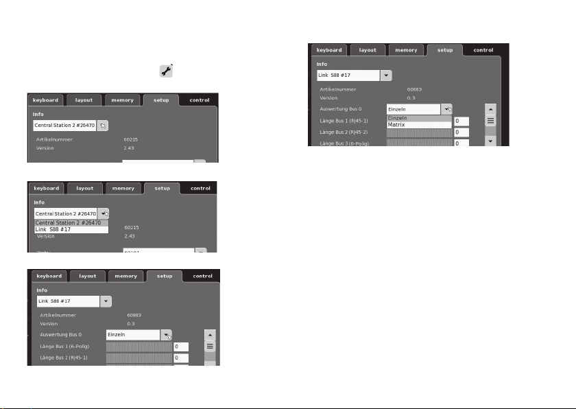
Confi guratie van de L88
Voor het in gebruik nemen van de L88 moet deze eerst
geconfi gureerd worden. Daarvoor gaat u in het CS naar
setup/info, nu met het sleuteltje
dus. Alle volgende afbeeldingen zijn voorbeelden.
naar de confi guratiemo-
nu kunnen verschillende gegevens ingesteld worden.
klap de info uit
kies Link S88#17
38
• Uitlezen Bus 0 (directe bus van de L88)
Instelling enkelvoudig = 16 meldcontacten
Instelling matrix = t/m 64 drukknoppen
• Lengte bus 1-3
Hier wordt ingesteld hoeveel S88 op elke bus zijn aangesloten (max. 31).
• Cyclustijd Bus 1-3
Afvraag cycli van de S88 bussen in ms (min. 10 ms - max.
1000 ms) invoeren ( af fabriek 100 ms)
• Bittijd S88
Instellen van de antwoordcycli ( af fabriek 167 us)
• Cyclustijd (Link 88) contact 1-16
Afvraag cycli van de Link contacten bij het gebruik als
railcontact 1 - 16.
• Cyclustijd drukknoppen
Afvraag cycli bij het gebruik als schakelpaneel (af fabriek 67 ms).
• Kolommen schakelpaneel
Aantal kolommen invoeren (max. 8) van de drukknoppenmatrix.
• Regels schakelpaneel
Aantal regels invoeren (max. 8) van de drukknoppenmatrix.
Page 39
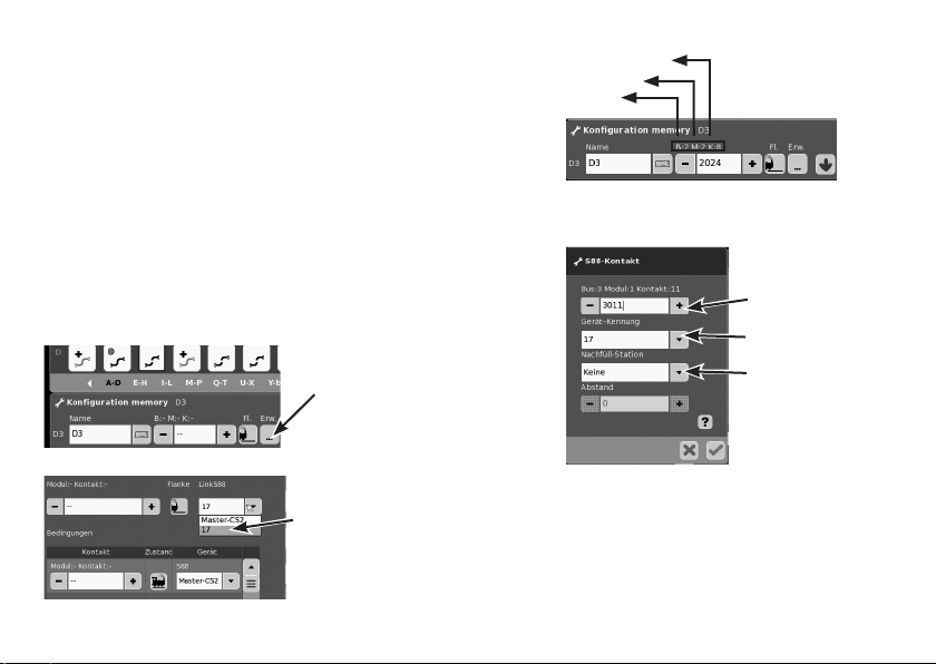
Adressering van de module:
De module adresseert zich automatisch bij het insteken.
Voor de instelling in het Central Station vindt u onderstaand
de adressen.
Contact (spoor): 1 - 16
Drukknop adressen 101-164
Bus 1: 1001 -1496 (bijv. 1005 = 1ste module, contact 5)
Bus 2: 2001 - 2496
Bus 3: 3001 - 3496
Voorbeelden van instellingen op het Central Station:
Instellingen op het Central Station:
1. Benutten als railcontact:
1.1 Gebruiken in het memory (voorbeeld) ga naar de
configuratiemodus
Via de toets “Meer”
naar de uitgebreide
instellingen springen.
Aangemeld apparaat kiezen
Voorbeeld: Meldcontact 8
Modul 2
Bus 2
1.2 Gebruiken in het layout (voorbeeld) ga naar de configuratiemodus en definieer het contact.
Adres (contact)
invoeren.
Apparaat kiezen
Functie kiezen, indien
nodig
Apparaat uitwisselen
Als een apparaat vervangen moet worden, kan de nieuwe L88
omgezet worden op het huidige apparatennummer. Het omzetten
gebeurt na het aanmelden van deLink 88 in het CS onder Setup
– Sleuteltje – Apparaten – bewerken. Geef daar de nieuwe
Link 88, het oude apparatennummer en bevestig dat. Daarna is
het noodzakelijk om het CS opnieuw op te starten, waarna alle
contacten weer als gewoonlijk werken.
39
Page 40

Voorbeelden voor het aansluiten van de verschillende meldcontacten
Massa retour voor alle railcontacten slechts 1x nodig.
Aansluiting aan het Märklin
H0-railsysteem met een
schakelrail
= Meldende rijrich-
ting
Rijrichtingafhankelijke
melding
Aansluiting aan het Märklin
H0-railsysteem met een
contactrails
Rijrichtingonafhankelijke
melding
40
Bus 1 Bus 2Bus 3
S 88 Link
T
1
2 3
S 88 Link
T
1
2 3
5V
7
6
4
8
5
5V
Bus 1 Bus 2Bus 3
7
6
4
8
5
91011
91011
12V
T
15
16
12
14
13
12V
T
15
16
12
14
13
Page 41
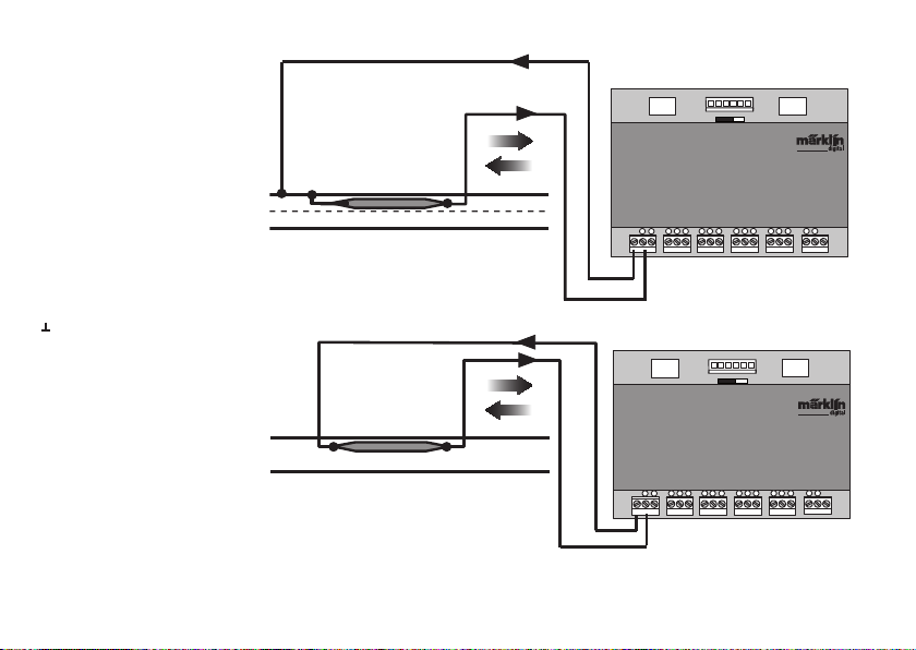
Aansluiting aan het Märklin H0railsysteem met een reedcontact
Rijrichtingonafhankelijke
melding
Massa retour is voor elk reedcontact nodig
Aansluiting aan het tweerailsysteem, onafhankelijk van
de modelspoorschaal alleen met
reedcontact.
Bus 1 Bus 2Bus 3
S 88 Link
T
1
2 3
5V
7
6
4
8
5
5V
Bus 1 Bus 2Bus 3
91011
12V
T
15
16
12
14
13
12V
Rijrichtingonafhankelijke
melding
S 88 Link
T
1
2 3
7
6
4
8
91011
5
T
15
16
12
14
13
41
Page 42
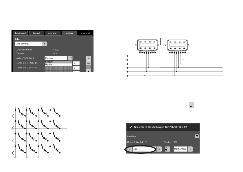
72720 / 72729 / 7272
Benutten als drukknoppen-matrix (schakelpaneel):
Wilt u de L88 gebruiken voor een drukknoppen-matrix, dan
moeten de volgende instellingen uitgevoerd worden.
Door de instelling matrix kunnen max. 64 drukknoppen (32
magneetartikelen of 64 rijwegen) ondersteunt worden. Voor
de opbouw is per drukknop een diode 1N4148 nodig. Let op de
inbouwrichting.
Contact 9-16 (ingang) Regels
9
12
10
11
Contact 1-8 (uitgang)
1
Kolommen
2
3
4
42
Aansluiten schakelkastjes
Er kunnen max. 8 schakelkastjes (ingang 9-16) aangesloten
worden.
Ingang
10
9
1
2
3
4
5
6
De instellingen worden in de conguratiemodus van het
memory gemaakt (zie gebruiksaanwijzing Central Station).
Nu moet aan elke knop een rijweg toegewezen worden.
Let er op dat de rijwegen in de memory op automaat bedrijf
ingesteld zijn.
De toewijzing gebeurd met de toets
instellingen voor de rijwegen.
Invoer voorbeeld:
U voert eerst het adres van de drukknop in (Zie tabel op blz 13).
in de uitgebreide
Uitgang
Page 43
daarna het toegewezen apparaat (hier 17) invoeren.
Adrestabellen voor de toetsen
Let er op, de diode moet in sperrichting naar de uitgang zijn
ingebouwd.
Voorbeeld Knop 1: 9 uitgang aangesloten op ingang 1 = adres
101.
(Ingang)
9
Is alles juist ingevoerd, bevestig dat met het groene vinkje.
Met de nu in het beeld verschijnende toets met de blauwe
pijl tussendoor opslaan. Daarna verdere rijwegen bewerken
of met het groene vinkje bevestigen en beëindigen.
Aanpakken van de toets (voorbeelden)
Knop 25 =125
Knop 26 = 126
toets
(Ingang)
12
11
18 - 24
25 - 32
10
9 - 17
Knop 9 = 109
9
1 - 8
Knop 1 = 101
1 (Uitgang)
Knop 2 = 102
2 (Uitgang)
1 (Uitgang)
Ingang
Uitgang
9 10 11 12 13 14 15 16
1 101 109 117 125 133 141 149 157
2 102 110 118 126 134 142 150 158
3 103 111 119 127 135 143 151 159
4 104 112 120 128 136 144 152 160
5 105 113 121 129 137 145 153 161
6 106 114 122 130 138 146 154 162
7 107 115 123 131 139 147 155 163
8 108 116 124 132 140 148 156 164
43
Page 44

Uso correcto
• El módulo de señalización de respuesta L88 se ha
previsto para su conexión a las Central Stations (CS2)
60213/60214/60215 a partir de la versión de software 3.8xx
y más recientes..
• Conexión de los módulos de señalización de respuesta
6088/60880/60881 y 60882 a las Central Stations antes
citadas.
• El módulo de señalización de respuesta L88 Link es un
señalizador de respuesta con 16 contactos de señalizaci-
ón para la vía de conductor central de Märklin H0 o para
vías 2L (ancho de vía 1, Trix H0, Minitrix) con contactos
de lámina (reed)
• o bien conexión hasta 64 pulsadores.
Instrucciones de seguridad
• La alimentación eléctrica del L88 Link se realiza exclusivamente mediante la fuente de alimentación conmutada
66361 o 66201.
• Los trabajos de conexionado en el módulo de señalización de respuesta L88 Link deben realizarse exclusivamente sin tensión.
• ¡ATENCIÓN! Esquinas y puntas afiladas condicionadas a
la función.
• La vivienda no se debe abrir.
• El módulo de señalización de respuesta L88 Link se ha
previsto exclusivamente para su uso en recintos secos.
44
Notas importantes
• Las instrucciones de empleo forman parte íntegra del
producto y, por este motivo, deben conservarse y entregarse al nuevo usuario, si se transmite el producto a otra
persona.
• Para reparaciones contacte con su proveedor Märklin
especializado.
• Responsabilidad y garantía conforme al documento de
garantía que se adjunta.
• Eliminación: www.maerklin.com/en/imprint.html
Entradas y salidas del Link 88
Alimentación eléctrica: fuente de alimentación conmutada
66361 o 66201.
Conexión a Central Station/Terminal
Retorno de masa (si se utiliza como señalizador de
respuesta)
1-16 Conexión de contacto (vía de conductor central de
Märklin H0 o pulsadores)
Bus 1 60881 o 60882
Bus 2 60881 o 60882
Bus 3 6088 y/o 60880
Interruptor para alimentación eléctrica de los módulos S88
a 5 V o 12 V.
Page 45
Interruptor de alimentación eléctrica S88/
S88AC/S88DC
Alimentación eléctrica 66361 o 66201
60881/60882
Bus 1 Bus 2Bus 3
60880/6088
5V
60881/60882
12V
Central Station /
Terminal
Retorno de
masa
S88 Link
T
1
456
2 3
Vía o pulsadores
7
8
91011
121314
Retorno de
masa
Conectar el Link 88 directamente a la conexión de refuerzo de la CS2 o al terminal 60125 y luego enchufar
la fuente de alimentación eléctrica 66361 o 66201.
Central Station /
Terminal
T
15
16
Montaje
Conexión a Central Station
12V
5V
Bus 1 Bus 2Bus 3
S88 Link
T
1
7
456
8
2 3
91011
121314
T
15
16
45
Page 46
Esquema sinóptico de conexionado
Es posible conectar a un Link 88 un máximo de 31 S88
y/o 62 S88AC/S88DC.
87654321
decoder s 88
910111213141516
Máx. 31x S88
Puede conservarse una conexión ya existente
del S88 en la Central Station 2.
Bus Bus
S88 AC o DC
46
Bus Bus
S88 AC
T
1
7
6
4
2 3
5
Máx. 31x
Alimentación eléctrica 66361+60822
CS2 o Terminal
S88 DC
T
1
7
456
2 3
T
15
8
91011
16
121314
Bus 3
Bus 2
Máx. 31x
S88 AC o DC
T
16
15
8
9
11
12
14
10
13
Bus 1
12V
5V
Bus 1 Bus 2Bus 3
Interruptor de alimentación eléctrica
S88/S88AC/S88DC = 5V/12V (ver
S88 Link
T
1
7
456
2 3
15
8
91011
121314
T
16
página siguiente)
Page 47
Alimentación eléctrica:
5 V en el modo mixto de productos de Märklin S88 y S88 AC/DC (como se muestra en la Fig.) así como productos de otros proveedores.
12V solo junto con S88 AC/DC. Si la alimentación eléctrica se realiza a 12 V, se reduce la propensión a fallos y averías.
Patillaje del conector RJ45
PIN S88 Nombre Descripción PIN RJ45
Color
EIA/TIA 568A
1 D ATA Datos de lectura 2 verde
2 GND Masa para señales y tensión de alimentación 3 blanco/naranja
2 GND 5 blanco/azul
3 CLOCK Señal de reloj de sincronización 4 azul
4 PS (LOAD) Carga la información en el bus 6 naranja
5 RESET Reset de las memorias de entradas 7 blanco/marrón
6 +5V/+12V Tensión de alimentación para los módulos de señalización de estado 1 blanco/verde
— SHIELD Pantalla de cable no conectada — —
Märklin no asume ninguna responsabilidad en el caso de uso común de productos de Märklin y productos de otros proveedores. Por lo cual recomendamos encarecidamente comprobar los patillajes de la toma RJ45 en cuestión.
47
Page 48
Confi guración del L88
Antes de la puesta en servicio del L88, éste debe
confi gurarse. Para ello, en la CS vaya a Setup/Info y con el
icono de herramienta
Todas las fi guras siguientes son ejemplos:
Despliegue la información
Seleccione el Link S88 #17,
48
acceda al modo Confi guración.
Ahora puede confi gurar los distintos datos.
• Análisi del bus 0 (bus directo del L88),
Con guración individual = 16 contactos de señalización
Con guración matricial = hasta 64 pulsadores
• Longitud de bus 1-3
Aquí se registra cuántos S88 están conectados a cada
bus (máx. 31).
• Tiempo de ciclo de bus 1-3
Registrar los ciclos de interrogación de los buses S88 en
ms (mín. 10 ms - máx. 1000 ms) (ajuste de fábrica a 100 ms).
• Tiempo de bit S888
Confi guración del ciclo de respuesta (ajuste de fábrica a 167µs)
• Tiempo de ciclo (Link 88), contacto 1 - 16
Tiempo de interrogación de los contactos Link si se
utilizan como contacto de vía 1-16.
• Tiempo de ciclo de teclado
Ciclo de interrogación si se utiliza como teclado (ajuste
de fábrica a 67 ms).
• Columnas de teclado
Introducción de las columnas (máx. 8) de la matriz de
teclado
Page 49
• Filas de teclado
Introducción de las filas (máx. 8) de la matriz de teclado
Direccionamiento de los módulos:
Los módulos se direccionan automáticamente al enchufarlos. Para la configuración de las direcciones en la Central
Station, éstas se incluyen a continuación.
Contactos (vía): 1-16
Direcciones de pulsadores: 101-164
Bus 1: 1001 - 1496 (p. ej., 1005 = 1er módulo, contacto 5)
Bus 2: 2001 - 2496
Bus 3: 3001 - 3496
Ejemplos de configuraciones en la Central Station
Configuración en la Central Station:
1. Uso como contacto de vía.
1.1 Uso en Memory (ejemplo),
vaya al modo Configuración
Con el botón Avanzadas, vaya a la configuración de Avanzadas.
Seleccionar dispositivo registrado
Ejemplo: Contactar 8
Modul 2
Bus 2
1.2 Uso en el layout (ejemplo)
Vaya al modo Configuración y defina el contacto
Introducción la dirección (contacto)
Seleccionar dispositivo
Seleccionar una función si es necesario
Sustitución del aparato.
Si es preciso sustituir el aparato, es posible reconfigurar el
nuevo L88 al número de dispositivo que tenía hasta ahora. El
cambio se produce después de registrar el Link 88 en la CS, en
Setup (Conguración) – Herramientas – Dispositivos. Introduzca
allí el número de dispositivo hasta ahora utilizado y confírmelo.
Acto seguido es preciso rearrancar la CS, con lo cual funcionan
todos los contactos como hasta ahora.
49
Page 50
Ejemplos de conexión de los diferentes contactos de señalzación
El retorno a masa para todos los contactos de vía se requiere 1 sola vez.
Conexión al sistema de
vías Märklin H0 con la vía
de conmutación
= Sentido de
marcha que señaliza
Señalización en función
del sentido de marcha
Conexión al sistema de
vías Märklin H0 con vías de
contacto
Señalización en función
del sentido de marcha
50
Bus 1 Bus 2Bus 3
S 88 Link
T
1
2 3
S 88 Link
T
1
2 3
5V
7
6
4
8
5
5V
Bus 1 Bus 2Bus 3
7
6
4
8
5
91011
91011
12V
T
15
16
12
14
13
12V
T
15
16
12
14
13
Page 51
Conexión al sistema de vías Märklin
H0 con contacto de láminas (reed)
Señalización en función del
sentido de marcha
Se requiere el retorno a masa por cada contacto de láminas (reed)
Conexión a sistemas de vías de
dos conductores independiente-
mente del tamaño de ancho de
vía solo con contacto de láminas
(reed).
Señalización en función del
sentido de marcha
Bus 1 Bus 2Bus 3
S 88 Link
T
1
2 3
S 88 Link
T
1
2 3
5V
7
6
4
8
5
5V
Bus 1 Bus 2Bus 3
7
6
4
8
5
91011
91011
12V
T
15
16
12
14
13
12V
T
15
16
12
14
13
51
Page 52
72720 / 72729 / 7272
Uso como matriz de teclas (pupitre de mando de agujas)
Si desea utilizar el L88 para una matriz de teclas, debe
realizar la siguiente configuración.
Mediante la configuración de matriz se puede soportar un
máx. de 64 pulsadores (32 artículos electromagnéticos o 64
itinerarios). Para el montaje, se necesita por cada pulsador
un diodo adicional 1N4148. Tener presente el sentido de
montaje.
10
filas de teclado
9
Contacto 1-8 (salida)
1
columnas de teclado
Contacto 9-16 (entrada)
12
11
2
3
4
52
Conexionado del pupitre de mando de agujas
Es posible conectar un máximo de 8 pupitres de mando de
agujas (entradas 9-16)
10
Entrada
9
1
2
3
4
5
6
7
8
La configuración se realiza en el modo Configuración del Memory (véanse Instrucciones de la Central Station)
Ahora debe asignarse a cada tecla un itinerario. Tenga presente
que los itinerarios en el Memory están configurados a Modo
Automático.
La asignación se realiza mediante la tecla
ón de opciones avanzadas de itinerario.
en la configuraci-
Ejemplo de configuración: Introduzca primero la dirección
asignada a la tecla (Ver tabla en página 53).
Salida
Page 53
A continuación, introduzca el dispositivo asignado (en este
caso 17).
Tabla de direcciones para las teclas
Tener presente que el diodo debe estar montado en el sentido de
bloqueo hacia la salida.
Ejemplo Botón 1: 9 salida conectada a la entrada 1 = dirección 101
Si ha introducido todo correctamente, confírmelo marcando el
gancho verde. En la imagen que aparece ahora en la pantalla,
guarde la configuración provisionalmente con la flecha azul.
Acto seguido edite itinerarios adicionales o confirme y
finalícelos con el gancho verde.
Dirigiéndose a la tecla (Ejemplo)
Tecla 25 =125
Tecla 26 = 126
Taster
(Entrada)
12
11
18 - 24
25 - 32
10
9 - 17
Tecla 9 = 109
9
1 - 8
Tecla 1 = 101
1 (Salida)
Tecla 2 = 102
2 (Salida)
(Entrada)
Entrada
Salida
9
1 (Salida)
9 10 11 12 13 14 15 16
1 101 109 117 125 133 141 149 157
2 102 110 118 126 134 142 150 158
3 103 111 119 127 135 143 151 159
4 104 112 120 128 136 144 152 160
5 105 113 121 129 137 145 153 161
6 106 114 122 130 138 146 154 162
7 107 115 123 131 139 147 155 163
8 108 116 124 132 140 148 156 164
53
Page 54

Impiego commisurato alla destinazione
• Il modulo di retroazione L88 è destinato al collegamento
alle Central Station (CS2) 60213/60214/60215 a partire dal
Software Versione 3.8.xx e superiore.
• Collegamento dei moduli di retroazione 6088/60880/60881
e 60882 alla sopra citata Central Station.
• Il modulo di retroazione L88 Link è un indicatore di retroazione con 16 contatti di avviso per il binario a conduttore
centrale Märklin H0 oppure binari a 2 rotaie (scartamento
1, Trix H0, Minitrix) con dei contatti Reed.
• rispettive connessioni sino a 64 tasti.
Avvertenze per la sicurezza
• L‘alimentazione di tensione dello L88 Link avviene esclusivamente tramite l’alimentatore “switching” da rete
66361 oppure 66201.
• I lavori di collegamento al modulo di retroazione L88 Link
devono avvenire soltanto nella condizione esente da
tensione.
• ATTENZIONE! Spigoli e punte acuminate per necessità
funzionali.
• L‘alloggiamento non deve essere aperto.
• Il modulo di retroazione L88 Link è destinato esclusiva-
mente all’utilizzo in ambienti asciutti.
54
Avvertenze importanti
•
Le istruzioni di impiego sono un elemento costitutivo del
prodotto e devono pertanto venire conservate nonché consegnate in dotazione in caso di ulteriore cessione del prodotto.
• Per riparazioni Vi preghiamo di rivolgerSi al Vostro rivenditore specialista Märklin.
• Prestazioni di garanzia e garanzia in conformità all’accluso certificato di garanzia.
• Smaltimento: www.maerklin.com/en/imprint.html
Entrate e uscite del Link 88
Alimentazione di corrente: alimentatore “switching” da rete
66361 oppure 66201.
Connessione alla Central Station / Terminale
Ritorno di massa (in caso di impiego come indicatore
di retroazione)
1-16 connessione di contatto (binario a conduttore
centrale Märklin H0 oppure tasto)
Bus 1 60881 oppure 60882
Bus 2 60881 oppure 60882
Bus 3 6088 e/o 60880
Commutatore per alimentazione di corrente del modulo S88
con 5V oppure 12V.
Page 55
Alimentazione di corrente del commutatore
S88/S88AC/S88DC
Alimentazione di
corrente 66361
oppure 66201
60881/60882
Bus 1 Bus 2Bus 3
60880/6088
5V
60881/60882
12V
Central Station /
Terminal
Ritorno di
massa
S88 Link
T
1
7
456
8
2 3
Binario oppure tasto
91011
Collegare il Link 88 direttamente alla connessione per Booster della CS2 oppure al terminale
60125, dopodiché innestare l’alimentazione di
corrente 66361 oppure 66201.
Central Station /
Terminal
121314
T
15
16
Ritorno di
massa
Collegamento
Collegamento alla Central Station
S88 Link
T
1
Bus 1 Bus 2Bus 3
456
2 3
12V
5V
T
91011
121314
15
16
7
8
55
Page 56
Panoramica delle connessioni
Ad un solo Link 88 possono venire connessi al massimo
31 S88 e/o 62 S88AC/S88DC.
decoder s 88
Max. 31x S88
Un preesistente collegamento dello S88 alla
Central Station 2 può venire mantenuto.
87654321
910111213141516
Bus Bus
Max. 31x
S88 AC oppure DC
Alimentazione di corrente 66361+60822
CS2 oder Terminal
56
Bus Bus
S88 AC
T
1
7
6
4
2 3
5
S88 DC
T
1
7
456
2 3
T
15
8
91011
16
121314
Bus 2
Max. 31x
S88 AC oppure DC
T
16
15
8
9
11
12
14
10
13
Bus 3
Bus 1
12V
S88 Link
T
1
2 3
Bus 1 Bus 2Bus 3
7
456
5V
15
8
91011
121314
Alimentazione di corrente del commutatore
S88/S88AC/S88DC = 5V/12V (vedi pagina
seguente)
T
16
Page 57
Alimentazione di corrente:
5V nell’esercizio promiscuo di prodotti Märklin S88 e S88 AC/DC (come rappresentato in g.), nonché di prodotti di altri fornitori.
12V solo in abbinamento con S88 AC/DC. In caso di un’alimentazione di corrente a 12V viene ridotta la vulnerabilità dai disturbi.
Assegnazione dei PIN del connettore RJ45
PIN S88 Nome Descrizione PIN RJ45
Colore
EIA/TIA 568A
1 D ATA Lettura dat 2 verde
2 GND Massa per segnali e tensione di alimentazione 3 bianco/arancio
2 GND 5 bianco/blu
3 CLOCK Segnale a impulso per la sincronizzazione 4 blu
4 PS (LOAD) Carica le informazioni sul Bus 6 arancio
5 RESET Ripristino della memoria di ingresso 7 bianco/marrone
6 +5V/+12V Tensione di alimentazione per i moduli di retroazione 1 bianco/verde
— SHIELD Schermatura del cavetto, non collegato — —
Märklin non si assume alcuna responsabilità in caso di utilizzo promiscuo di prodotti Märklin e prodotti di altri venditori, noi
consigliamo pertanto assolutamente di verificare le assegnazioni dei PIN delle rispettive connessioni RJ45.
57
Page 58
Confi gurazione dello L88
Prima della messa in servizio dello L88 questo deve venire
confi gurato. A tale scopo vogliate andare nella CS su setup/
Info, adesso con il simbolo „Attrezzi“
confi gurazione. Tutte le illustrazioni seguenti sono esempi:
espandete la Info
selezionate Link S88 #17,,
58
nella modalità di
adesso i singoli dati possono venire impostati.
• Valutazione Bus 0 (Bus diretto dello L88),
Impostazione singola = 16 contatti di retroazione
Impostazione matrice = sino a 64 tasti
• Lunghezza Bus 1-3
Qui viene registrato quanti S88 sono collegati a ciascun
Bus (max. 31).
• Durata del ciclo Bus 1-3
Introdurre i cicli di interrogazione dei Bus S88 in ms (min
10ms - max. 1000 ms) (di fabbrica 100ms).
• Durata dei Bit S88
Impostazione del ciclo della risposta (di fabbrica 167µs)
• Durata del ciclo (Link 88) contatti 1 - 16
Ciclo di interrogazione dei contatti Link in caso di impiego
come contatti di binario 1 - 16.
• Durata del ciclo di tastiera
Ciclo di interrogazione in caso di impiego come tastiera
(di fabbrica 67ms).
• Colonne della tastiera
Impostazione delle colonne (max. 8) della matrice di
tastiera
Page 59
• Righe della tastiera
Impostazione delle righe (max. 8) della matrice di tastiera
Indirizzamento dei moduli
I moduli si indirizzano automaticamente mediante l’innesto.
Per le impostazioni nella Central Station potete trovare gli
indirizzi qui di seguito.
Contatti (di binario): 1-16
Indirizzi dei tasti: 101-164
Bus 1: 1001 -1496 (ad es. 1005 = 1° modulo, contatto 5)
Bus 2: 2001 - 2496
Bus 3: 3001 - 3496
Esempi di impostazioni sulla Central Station
Impostazioni sulla Central Station:
1. Utilizzo come contatto di binario:
1.1 Impiego nella Memory (esempio) andate nella modalità
di configurazione
Tramite il tasto saltare
nella impostazione
estesa.
Selezionare l’apparato
registrato
Esempio : Contatto 8
Modul 2
Bus 2
1.2 Impiego nell’impianto (esempio) andate nella modalità
di configurazione e definite il contatto
Introdurre l’indirizzo
(contatto)
Selezionare l’apparato
Selezionare la funzione, quando necessario
Sostituzione di un apparato.
Se diviene necessaria la sostituzione di un apparato, il nuovo L88
può venire convertito al numero di apparato preesistente. Tale
conversione avviene dopo registrazione del Link 88 nella CS sotto
“setup - strumenti - apparati – elaborazione”. Introducete colà al
nuovo Link 88 il Vostro preesistente numero di apparato e confer-
mate questo. Dopo di ciò è necessario un nuovo avvio della CS,
adesso tutti i contatti funzionano come di consueto.
59
Page 60
Esempi per il collegamento dei differenti contatti di notifica
Ritorno di massa per tutti i contatti del binario solo 1x necessario.
Connessione al sistema di
binario Märklin H0 con il
binario di commutazione
= Notica dipendente dalla direzione di
marcia.
Notifica dipendente dalla
direzione di marcia.
Connessione al sistema
di binario Märklin H0 con
binari di contatto
Notifica indipendente
dalla direzione di marcia.
60
Bus 1 Bus 2Bus 3
S 88 Link
T
1
2 3
S 88 Link
T
1
2 3
5V
7
6
4
8
5
5V
Bus 1 Bus 2Bus 3
7
6
4
8
5
91011
91011
12V
T
15
16
12
14
13
12V
T
15
16
12
14
13
Page 61
Connessione al sistema di binario
Märklin H0 con contatto Reed
Notifica indipendente dalla
direzione di marcia.
Il ritorno di massa è necessario per ogni contatto Reed
Connessione a sistemi di binario
a due rotaie, indipendentemente
dalla dimensione dello scartamento solo con contatto Reed
Notifica indipendente dalla
direzione di marcia.
Bus 1 Bus 2Bus 3
S 88 Link
T
1
2 3
S 88 Link
T
1
2 3
5V
7
6
4
8
5
5V
Bus 1 Bus 2Bus 3
7
6
4
8
5
91011
91011
12V
T
15
16
12
14
13
12V
T
15
16
12
14
13
61
Page 62

Utilizzo come matrice di tasti (quadro di comando)
Se Voi desiderate utilizzare lo L88 per una matrice di tasti,
allora devono venire intraprese le seguenti impostazioni.
Tramite l’impostazione come matrice possono venire supportati al max. 64 tasti (32 apparati elettromagnetici oppure
64 itinerari). Per tale montaggio si ha bisogno in aggiunta
per ogni tasto di un diodo 1N4148, si presti attenzione alla
direzione di montaggio.
Contatti 9-16 (Ingresso) righe della tastiera
9
12
10
11
Contatti 1-8 (Uscita)
1
Colonne della tastiera
2
3
4
62
Connessione quadro di comando
possono venire collegati al max. 8 quadri di comando
(Ingressi 9 - 16).
72720 / 72729 / 7272
10
Ingresso
9
1
2
3
4
5
6
7
8
Le impostazioni avvengono nella modalità di configurazione
della Memory (si vedano le istruzioni della Central Station).
Ora ciascun tasto deve venire assegnato a un dato itinerario
di marcia. Vogliate prestare attenzione affinché gli itinerari
nella Memory siano impostati su esercizio automatico.
L’assegnazione avviene tramite i tasti nelle impostazioni
estese per un itinerario di marcia.
Inserimento ad es:
Voi inserite anzitutto l’indirizzo del tasto (Vedi tabella a pagina 63).
Uscita
Page 63
Dopodiché introducete l’apparato coordinato (qui 17).
Se tutto è inserito correttamente, vogliate confermarlo con
il marcatore verde. Sull’immagine che appare adesso sul
visore con la freccia blu fate una memorizzazione interme-
dia. Dopo di ciò elaborate ulteriori itinerari di marcia oppure
confermate con il marcatore verde e terminate.
Indirizzamento il tasto
Tasto 25 =125
Tasto 26 = 126
Taster
12
25 - 32
(Ingresso)
11
18 - 24
10
9 - 17
Tasto 9 = 109
9
1 - 8
Tasto 1 = 101
1 (Uscita)
Tasto 2 = 102
2 (Uscita)
Tabella di indirizzi per i tasti
Si prega di fare attenzione, il diodo deve venire installato in
direzione di blocco verso l’uscita.
Esempio Button 1: 9 uscita collegata all‘ingresso 1 = Indirizzo
del 101
(Ingresso)
Ingresso
Uscita
9
1 (Uscita)
9 10 11 12 13 14 15 16
1 101 109 117 125 133 141 149 157
2 102 110 118 126 134 142 150 158
3 103 111 119 127 135 143 151 159
4 104 112 120 128 136 144 152 160
5 105 113 121 129 137 145 153 161
6 106 114 122 130 138 146 154 162
7 107 115 123 131 139 147 155 163
8 108 116 124 132 140 148 156 164
63
Page 64
Användning av produkten
• Återkopplingsmodulen L88 är avsedd att anslutas till
Central Station (CS2) 60213/60214/60215 med mjukvaruversion 3.8.xx eller senare.
• Anschluss der Rückmeldemodule 6088/60880/60881 und
60882 an oben genannte Central Station.
• Återkopplingsmodul L88 Link är en återkopplare med
16 kopplingskontakter för Märklin H0-mittledarräls eller
2-ledarräls (Spår 1, Trix H0, Minitrix) med reed-kontakter.
• t. ex. för anslutning med upp till 64 kontaktknappar.
Säkerhetsanvisningar
• För strömförsörjning av L88 Link får endast en nätenhet
66361 eller en 66201 användas.
• Anlutningsarbeten med återkopplingsmodul L88 Link får
endast göras i strömlöst tillstånd.
• VARNING! Funktionsbetingade skarpa kanter och spetsar.
• Bostäder får inte öppnas.
• Återkopplingsmodul L88 Link får endast användas i torra
rum och utrymmen.
Viktig information
• Die Bedienungsanleitung ist Bestandteil des Produktes •
Bruksanvisningen tillhör produkten och måste därför
sparas och medfölja produkten vid eventuellt avyttrande.
• För reparationer vänder man sig till sin Märklin-fackhandel.
• Responsabilidad y garantía conforme al documento de
garantía que se adjunta.
• Hantering som avfall: www.maerklin.com/en/imprint.html
64
In- och utgångar på Link 88
Strömförsörjning: Nätenhet 66361 eller 66201.
Anslutning till Central Station / Terminal Jordåterkoppling
(när den används som återkopplare)
1-16 Kontaktanslutningar (Märklin H0 mittledarräls
eller knappkontakter)
Bus 1 60881 eller 60882
Bus 2 60881 eller 60882
Bus 3 6088 och/eller 60880
Omkopplare för strömförsörjning av S88 Modul med 5V eller 12V
60881/60882
Omkopplare för
strömförsörjning
S88/S88AC/S88DC
Strömförsörjning
60881/60882
60880/6088
5V
Bus 1 Bus 2Bus 3
12V
66361 eller 66201
Central Station /
Terminal
Jordåter-
koppling
S88 Link
T
1
7
456
2 3
Spår eller knappar
T
121314
15
16
8
91011
Jordåter-
koppling
.
Page 65
Anslutning
Anslutning till Central Station
Link 88 ansluts direkt till Boosteranslutningen på CS2 eller till Terminal 60125.
För strömförsörjningen ansluter man därefter en nätenhet 66361, eller 66201.
5V
Bus 1 Bus 2Bus 3
12V
Central Station /
Terminal
S88 Link
T
1
2 3
456
T
121314
15
16
7
8
91011
65
Page 66
Översikt: Anslutninga
Till en Link 88 kan man maximalt ansluta 31 st S88
och/eller 62 st S88AC/S88DC
87654321
decoder s 88
910111213141516
Max. 31x S88
En befintlig anslutning av S88 till Central
Station 2 kan bibehållas.
Bus Bus
Max 31x
S88 AC eller DC
CS2 eller Terminal
66
Bus Bus
S88 AC
T
1
7
6
4
2 3
5
T
15
8
91011
16
121314
Bus 1
Strömförsörjning 66361+60822
S88 Link
T
1
2 3
Bus 3
Bus 1 Bus 2Bus 3
7
456
S88 DC
T
1
7
456
2 3
Max 31x
Bus 2
S88 AC eller DC
12V
5V
Omkopplare för strömförsörjning
T
16
15
8
9
11
12
14
10
13
S88/S88AC/S88DC = 5V/12V (på
nästa sida)
T
15
8
91011
16
121314
Page 67

Strömförsörjning:
5V i blandad trak mellan Märklins produkter S88 och S88 AC/DC (så som visas på bilden), samt med produkter från andra tillverkare.
12V endast i förbindelse med S88 AC/DC. Vid strömförsörjning med 12V blir risken för eventuella strömningar mindre.
PIN-beläggningen av kontakterna till RJ45
PIN S88 Namn Beskrivning PIN RJ45
Färg
EIA/TIA 568A
1 D ATA Urvalsdata 2 grönt
2 GND Jord för signaler och strömmatning 3 vitt/orange
2 GND 5 vitt/blått
3 CLOCK Taktsignal för synkroniseringen 4 blått
4 PS (LOAD) Laddar informationen i Bussen 6 orange
5 RESET Återställning av ingångsvärden 7 vitt/brunt
6 +5V/+12V Strömförsörjning av återkoppligsmoduler 1 vitt/grönt
— SHIELD Kabelskärm, ej ansluten — —
Märklin ansvarar inte för följderna om Märklins produkter nyttjas tillsammans med produkter av andra fabrikat. Vi rekommenderar därför att alltid noga kontrollera PIN-beläggningarna till varje enskild RJ45-anslutning i detta avseende.
67
Page 68
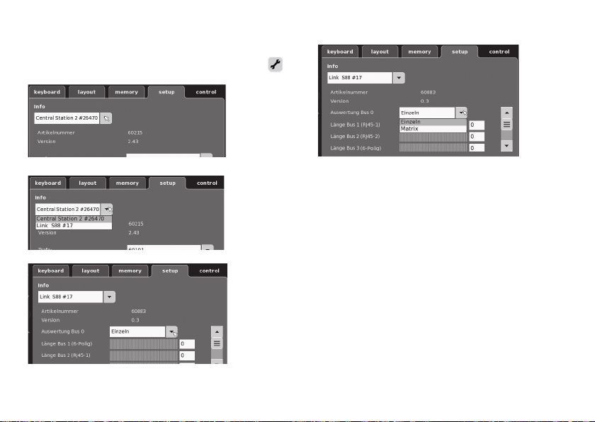
Konfi guration av L88
Innan L88 tas i bruk måste den först konfi gureras. För detta
går man på CS in på setup/info, nu med verktygssymbolen
i konfi gurationsläge. Samtliga följande bilder är
exempel:
nu kan man ställa in enskilda data.
Man klickar på Info
Man väljer sedan Link S88#17,
68
• Utvärdering Bus 0 (direkt Bus till L88), inställning av
enskilda = 16 anslutningskontakter inställning av matris =
upp till 64 knappar
• Längd Bus 1-3
Här anges hur många S88 som anslutits till respektive
Bus (max 31).
• Tidscykel Bus 1-3
Inställning av frågecykler för S88 Bussar i ms (min 10ms -
max 1000 ms). (Fabriksinställning 100 ms).
• Bit-tid S88
Inställning av svarscykel (fabriksinställning 167µs)
• Tidscykel (Link 88) för kontakt 1 - 16
Link-kontakternas frågecykel vid användning som spår-
kontakt 1 - 16.
• Tangentbord för tidscykler
Frågecykel vid användning som tangentbord (fabriks-
inställning 67ms).
• Tangentbordskolumner
Inskrivning i kolumner (max 8) i tangentbordets matris
Page 69

• Rader för tangentbord
Inställning av tangentbords-matrisens rader (max 8)
Adressering av moduler:
Modulerna adresseras automatiskt när konakten ansluts.
För inställningar via Central Station används följande adresser.
Kontakter (spår): 1-16
Tangentbordsadresser: 101-164
Bus 1: 1001 -1496 (t.ex. 1005= 1. modul, kontakt 5)
Bus 2: 2001 - 2496
Bus 3: 3001 - 3496
Exempel på inställningar via Central Station:
Inställningar via Central Station:
1. Användning som spårkontakt:
1.1 Användning med memory (exempel)
Gå in i konfigurations-läge
Tryck på knappen för
att komma till avancerade inställningar.
Välj anmäld enhet
Exempel: Kontakt 8
Modul 2
Bus 2
1.2 Användning i spårplans-layout (exempel)
Gå in i konfigurations-läge och definiera kontaktent
Skriv in adress
(kontakt)
Välj enhet
Välj funktion, när så
erfordras
Enhetsbyte
Om ett enhetsbyte fordras kan den nya L88 ställas in på samma
enhetsnummer som tidigare. Inställningen görs efter att Link 88
anmält sej i CS under: setup - verkstygssymbol - enhet. Använd
samma enhetsnummer som tidigare och spara detta. Sedan
måste CS startas om och då kommer alla funktioner att fungera
som vanligt igen.
69
Page 70
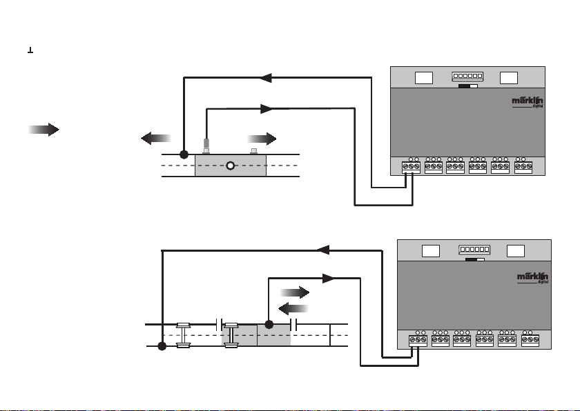
Exempel på anslutning av olika givares kontakter
Jordåterkoppling för samtliga spår-kontakter - endast 1x behövs.
Anslutning till Märklins
H0-spårsystem med kopplingsskena
= Av givare angiven
körriktning
Körriktningsberoende
kontaktmeddelande
Anslutning till Märklin
H0-spårsystem med kontaktskenor
Oberoende av riktningen
kontaktmeddelande
70
Bus 1 Bus 2Bus 3
S 88 Link
T
1
2 3
S 88 Link
T
1
2 3
5V
7
6
4
8
5
5V
Bus 1 Bus 2Bus 3
7
6
4
8
5
91011
91011
12V
T
15
16
12
14
13
12V
T
15
16
12
14
13
Page 71
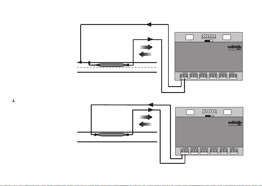
Anslutning till Märklins
H0-spårsystem via Reed-kontakt.
Oberoende av riktningen kontaktmeddelande
Jordåterkoppling måste ske via Reed-kontakt
Anslutninga till tvåspårs-system,
oberoende av spårvidd, endast
med Reed-kontakt
Oberoende av riktningen kontaktmeddelande
Bus 1 Bus 2Bus 3
S 88 Link
T
1
2 3
S 88 Link
T
1
2 3
5V
7
6
4
8
5
5V
Bus 1 Bus 2Bus 3
7
6
4
8
5
91011
91011
12V
T
15
16
12
14
13
12V
T
15
16
12
14
13
71
Page 72

72720 / 72729 / 7272
Användning som knapp-matris (ställpult):
Vill man använda L88 som en knapp-matris (ställpult), så
måste följande inställningar göras.
Via inställningar av matrisen kan max 64 knappar användas
(till 32 magnetartiklar eller 64 körsträckor). För montage
av detta behövs en extra diod 1N4148 per knapp - tänk på
diodens riktning vid montaget.
Kontakt 9-16 (ingång)
12
11
rader
9
10
Kontakt 1-8 (utgång)
1
kolumner
2
3
4
72
Anslutning av ställpult
Man kan ansluta max 8 ställpultar (ingång 9 - 16)
10
Ingång
9
Inställningarna görs via Memorys konfigurations-läge (se
Central Stations bruksanvisning).
Nu måste varje knapp tilldelas en körsträcka. OBSERVERA
att körsträckorna i Memory är inställda på automat-trafik.
Indelningen görs via knappen för avancerade inställningar
av körsträckor.
Exempel på inskrivning:
Ange först knappens adress (se tabell sidan 73).
1
2
3
4
5
6
7
8
Utgång
Page 73
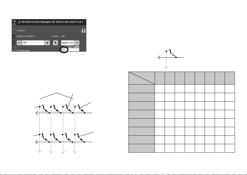
Därefter väljs önskad enhet (här nr 17).
Adresstabell för knapparna
Var god observera att dioder måste byggas in i rätt riktning i
förhållande till utgången
Exempel Knapp 1: 9 utgång ansluten till ingång 1 = adress 101.
Är allt korrekt inskrivet, bekräftar man detta med den gröna
bocken. På den bild som nu visas på displayen bekräftas
inställningen med den blå pilen. Därefter bearbetar man
ytterligare körsträckor eller så bekräftar man inställningarna
och avslutar med den gröna bocken.
Adresse på knappen (exempel)
Knapp 25 =125
Knapp 26 = 126
Knappen
(ingång
12
11
18 - 24
25 - 32
10
9 - 17
Knapp 9 = 109
9
1 - 8
Knapp 1 = 101
1 (utgång
Knapp 2 = 102
2 (utgång)
(ingång)
Ingång
Utgång
9
1 (utgång)
9 10 11 12 13 14 15 16
1 101 109 117 125 133 141 149 157
2 102 110 118 126 134 142 150 158
3 103 111 119 127 135 143 151 159
4 104 112 120 128 136 144 152 160
5 105 113 121 129 137 145 153 161
6 106 114 122 130 138 146 154 162
7 107 115 123 131 139 147 155 163
8 108 116 124 132 140 148 156 164
73
Page 74
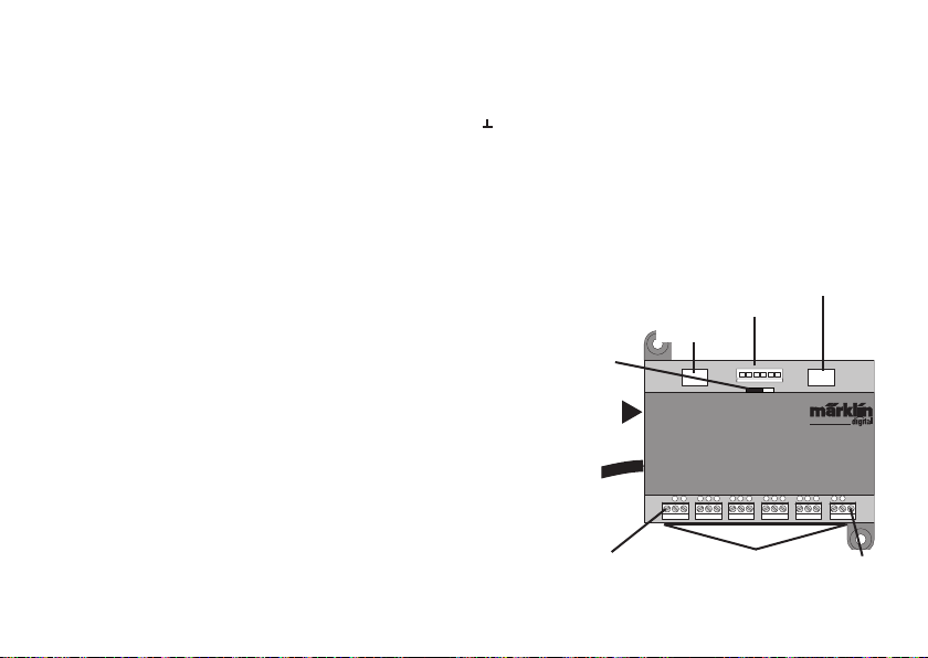
Hensigtsmæssig anvendelse
• Tilbagemeldingsmodulet L88 er udviklet til forbindelse
med Centralstationerne (CS2) 60213/60214/60215 fra
softwareversion 3.8.xx og højere.
Forbindelse med tilbagemeldingsmodulerne 6088/60880/60881
•
og 60882 sker via ovennævnte Centralstation.
• Tilbagemeldingsmodulet L88 Link er et tilbagemeldingsmodul med 16 meldingskontakter til Märklin H0-mellemlederskinnereller 2L skinner (Spor 1, Trix H0, Minitrix) med
Reed kontakter.
• Eller forbindelse af op til 64 taster.
Sikkerhedshenvisninger
• Spændingsforsyningen til L88 Link må udelukkende ske
via forsyningsdelene 66361 eller 66201.
• Forbindelsesopgaver på tilbagemeldingsmodulet L88 Link
må udelukkende ske i spændingsfri tilstand.
• ADVARSEL! Funktionsbetingede skarpe kanter og spidser.
• Boliger må ikke åbnes.
• Tilbagemeldingsmodulet L88 Link er udelukkende egnet til
anvendelse i tørre rum.
Vigtige bemærkninger
• Betjeningsvejledningen er en del af produktet og skal
derfor opbevares og følge med, hvis produktet gives
videre.
• I tilfælde af reparationer ret da henvendelse til din
Märklin-forhandler
• Garanti ifølge vedlagte garantibevis.
• Bortskafning: www.maerklin.com/en/imprint.html
74
Ind- og udgange på Link 88
Strømforsyning: Forsyningsdel 66361 eller 66201.
Tilslutning til Centralstation / terminal:
Massetilbageførsel (ved anvendelse som tilbagemelder)
1-16 kontaktforbindelse (Märklin H0 mellemlederskinne
eller taster)
Bus 1 60881 eller 60882
Bus 2 60881 eller 60882
Bus 3 6088 og/eller 60880
Kontakt til strømforsyning på S88 moduler med 5V eller 12V.
60881/60882
60880/6088
Kontakt strømforsyning
60881/60882
S88/S88AC/S88DC
Strømforsyning
Bus 1 Bus 2Bus 3
12V
5V
66361 eller 66201
Central Station /
Terminal
Massetilba-
geførsel
S88 Link
T
1
456
2 3
Skinne eller taster
T
121314
15
16
7
8
91011
Massetilba-
geførsel
Page 75
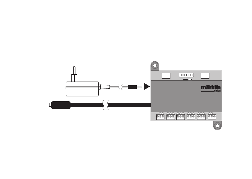
Tilslutning
Tislutning til Centralstation
Tilslut Link 88 direkte på boostertilslutningen på CS2 eller terminal 60125, og
tilslut derefter strømforsyningen 66361 eller 66201.
5V
Bus 1 Bus 2Bus 3
12V
Central Station /
Terminal
S88 Link
T
1
2 3
456
T
121314
15
16
7
8
91011
75
Page 76
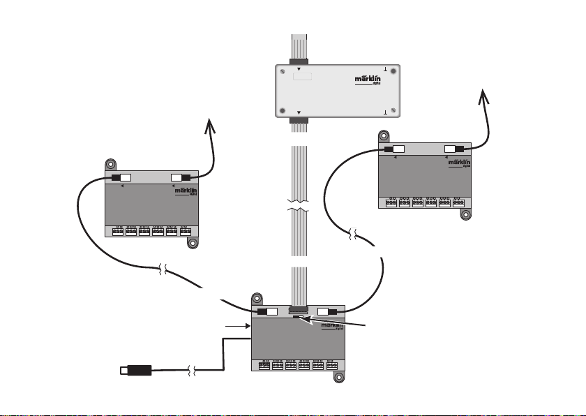
Tilslutningsoversigt
Der må maksimalt tilsluttes 31 S88 og/eller 62 S88AC/
S88DC til Link 88.
87654321
decoder s 88
910111213141516
Maks. 31x S88
På Central Station 2 kan der bibeholdes en
bestående tilslutning af S88.
Bus Bus
Maks. 31x
S88 AC eller DC
CS2 eller Terminal
76
Bus Bus
S88 AC
T
1
7
6
4
2 3
5
T
15
8
91011
16
121314
Strømforsyning 66361+60822
Bus 1
S88 Link
T
1
2 3
Bus 3
Bus 1 Bus 2Bus 3
7
456
S88 DC
T
1
7
456
2 3
T
16
15
8
9
11
12
14
10
13
Maks. 31x
S88 AC eller DC
Bus 2
12V
5V
Kontakt strømforsyning
S88/S88AC/S88DC = 5V/12V
(se næste side)
T
15
8
91011
16
121314
Page 77
Strømforsyning:
5V ved blandet drift af Märklinprodukterne S88 og S88 AC/DC (som vist på ill. ) samt med andre producenters produkter.
12V kun i forbindelse med S88 AC/DC. Med en strømforsyning på 12V mindskes risikoen for fejl.
PIN-belægning på RJ45-stikket
PIN S88 Navn Beskrivelse PIN RJ45
Farve
EIA/TIA 568A
1 D ATA Udlæsedata 2 grøn
2 GND Masse til signaler og forsyningsspænding 3 hvid/orang
2 GND 5 hvid/blå
3 CLOCK Taktsignal til synkronisering 4 blå
4 PS (LOAD) Indlæser informationerne i bussen 6 orang
5 RESET Tilbage til indgangshukommelsen 7 hvid/brun
6 +5V/+12V Forsyningsspænding til tilbagemeldingsmodulerne 1 hvid/grøn
— SHIELD Kabelafskærmning, ikke tilsluttet —
—
Märklin hæfter ikke ved fælles anvendelse af Märklin-produkter og produkter fra andre fabrikanter, vi anbefaler derfor at
kontrollere PIN belægningen på den pågældende RJ45-forbindelse.
77
Page 78
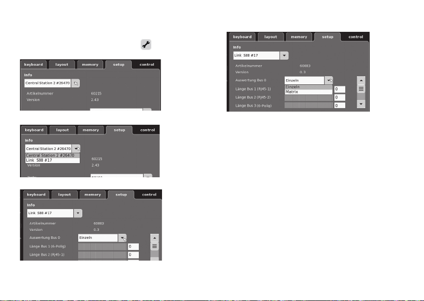
Konfi guration af L88
L88 skal konfi gureres inden opstart. Se dertil afsnittet setup/
Info i CS, nu vist med værktøjssymbolet
modus. Alle følgende fi gurer er eksempler:
i konfi gurations-
hvorefter de enkelte data kan indstilles.
åbn menupunktet Info
Vælg Link S88 #17,
78
• Analyse Bus 0 (direkte bus på L88),
Indstilling enkeltvis = 16 meldekontakter
Indstilling matrix = op til 64 taster
• Længde bus 1-3
Her indtastes hvor mange S88, der er tilsluttet på hver
bus (maks. 31).
• Cyklustid bus 1-3
Indtast forespørgselscyklusser for S88 busser i ms (min.
10ms - maks. 1000 ms) (fra fabrikken: 100ms).
• Bit tid S88
Indstilling af cyklussens responstid (fra fabrikken: 167µs)
• ZCyklustid (Link 88) Kontakt 1 - 16
Forespørgselscyklus af Linkkontakterne til anvendelse
som skinnekontakt 1 - 16.
• Cyklustid tastatur
Forespørgselscyklus til anvendelse som tastatur (fra
fabrikken: 67ms).
• Spalter tastatur
Indtastning af tastaturmatrixens linjer (maks. 8)
Page 79
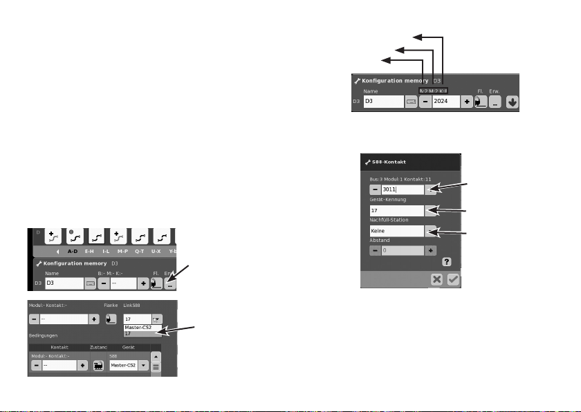
• Linjer tastatur
Indtastning af tastaturmatrixens linjer (maks. 8)
Adressering af moduler:
Modulerne adresseres automatisk efter tilslutning. Til indstilling af Centralstation ses adresserne nedenfor.
Kontakter (skinne): 1-16
Tasteradresser: 101-164
Bus 1: 1001 -1496 (f. eks. 1005 = 1. modul, kontakt 5)
Bus 2: 2001 - 2496
Bus 3: 3001 - 3496
Eksempler på indstillinger af Centralstation:
Indstillinger af Centralstation:
1. Anvendelse som skinnekontakt:
1.1 Anvendelse i hukommelsen (eksempel); åbn kongurationsmodus
Spring via knappen til
avancerede indstillinger.
Vælg tilmeldt enhed
eksempel: Kontakt 8
Modul 2
Bus 2
1.2 Anvendelse i Layout (eksempel); åbn kongurationsmodus og definér kontakten
Indtast adresse
(kontakt)
Vælg enhed
Vælg funktion efter
behov
Udskiftning af enhed.
Hvis der blive behov for udskiftning af enhed, kan den nye L88
omstilles til alle hidtidige enhedsnumre. Omstillingen sker efter
tilmelding af Link 88 i CS under setup - værktøj - enheder - bearbejd. Indtast her det nye Link 88 under det hidtidige enheds-
nummer og bekræft. Derefter er det nødvendigt at genstarte CS,
hvorefter alle kontakter fungerer på normal vis.
79
Page 80
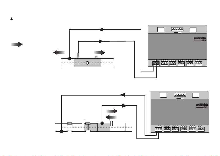
Eksempler på forbindelse af forskellige meldekontakter
Massetilbageførsel til alle skinnekontakter er kun 1x nødvendig.
Forbindelse med
MärklinH0-skinnesystemet
med spændingsskinnen
= meldende kør-
selsretning
Melding, der er afhængig
af kørselsretningen.
Forbindelse med
Märklin H0-skinnesystemet
med kontaktskinnerne
Melding, der er uafhængig
af kørselsretningen
80
Bus 1 Bus 2Bus 3
S 88 Link
T
1
2 3
S 88 Link
T
1
2 3
5V
7
6
4
8
5
5V
Bus 1 Bus 2Bus 3
7
6
4
8
5
91011
91011
12V
T
15
16
12
14
13
12V
T
15
16
12
14
13
Page 81

Forbindelse med MärklinH0skinnesystemet med reedkontakt.
Melding, der er uafhængig af
kørselsretningen
Massetilbageførsel er nødvendig pr. reedkontakt
Forbindelse med toleder-skinnesystemer, uafhængig af sporstørrelse kun med reed kontakt.
Melding, der er uafhængig af
kørselsretningen
Bus 1 Bus 2Bus 3
S 88 Link
T
1
2 3
S 88 Link
T
1
2 3
5V
7
6
4
8
5
5V
Bus 1 Bus 2Bus 3
7
6
4
8
5
91011
91011
12V
T
15
16
12
14
13
12V
T
15
16
12
14
13
81
Page 82
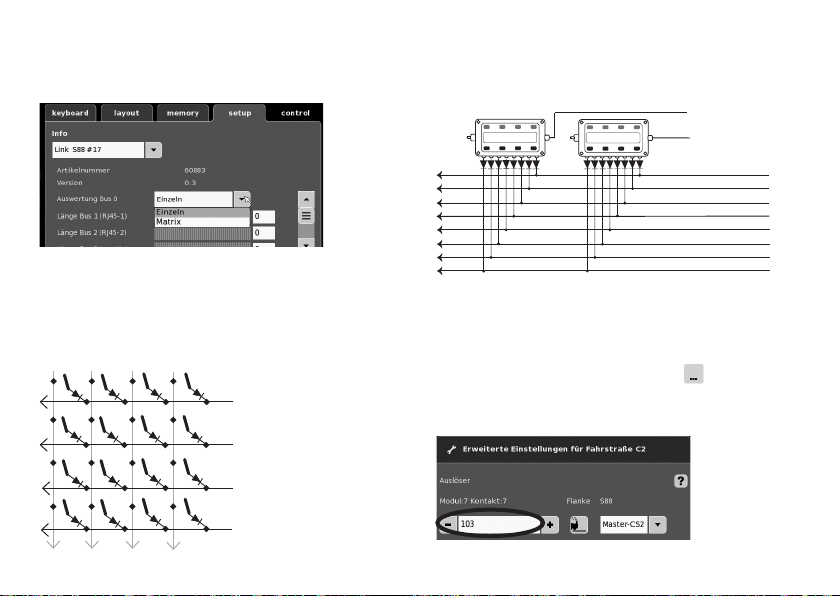
72720 / 72729 / 7272
Anvendelse som tastematrix (kontrolpanel)
Hvis L88 skal anvendes som tastematrix, skal følgende
indstilles.
Via indstillingen Matrix kan der maks. understøttes 64 taster
(21 magnetartikler eller 64 køreveje). Bemærk, at der til
opbygningen pr. taster skal bruges en diode 1N4148; bemærk
monteringsretning.
Kontakt 9-16 (indgang) linijer
9
12
10
11
Kontakt 1-8 (udgang)
1
spalter
2
3
4
82
Tilslutningkontrolpanel
Der kan maks. tilsluttes 8 kontrolpaneler (indgang 9 - 16).
10
Indgang
9
1
2
3
4
5
6
7
8
Indstillingerne foretages i hukommelsens konfigurationsmodus (se Centralstationens vejledning).
Nu skal hver taster indordnes under en kørevej. Bemærk, at
kørevejene i hukommelsen er indstillet på Automatikdrift.
Indordningen foretages ved hjælp af tasten
indstillinger af køreveje.
i avancerede
Eksempel på indtastning:
Indtast først tastens adresse (Se tabel side 13).
Udgang
Page 83
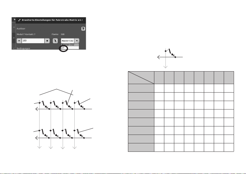
Indtast derefter den indordnede enhed (her 17).
Adressetabel til tasterne
Bemærk, at diodenskalvære indbygget med spærreretningen
hen imod udgangen.
Eksempel Knap 1: 9 udgang forbundet til indgang 1= adress i 101
Når alt er indtastet korrekt, bekræftes dette ved hjælp af
det grønne flueben. Gem ved hjælp af den blå pil, der nu
vises på det aktuelle skærmbillede. Det er derefter muligt at
bearbejde yderligere køreveje eller at bekræfte og afslutte
ved hjælp af det grønne flueben.
Adressieren är knappen (eksempel)
Taste 25 =125
Taste 26 = 126
Taster
(indgang)
12
11
18 - 24
25 - 32
10
9 - 17
Taste 9 = 109
9
1 - 8
Taste 1 = 101
1 (udgang)
Taste 2 = 102
2 (udgang)
(indgang)
Indgang
Udgang
9
1 (Udgang)
9 10 11 12 13 14 15 16
1 101 109 117 125 133 141 149 157
2 102 110 118 126 134 142 150 158
3 103 111 119 127 135 143 151 159
4 104 112 120 128 136 144 152 160
5 105 113 121 129 137 145 153 161
6 106 114 122 130 138 146 154 162
7 107 115 123 131 139 147 155 163
8 108 116 124 132 140 148 156 164
83
Page 84
Due to different legal requirements regarding electro-magnetic compatibility,
this item may be used in the USA only after separate certification for FCC compliance and an adjustment if necessary.
Use in the USA without this certification is not permitted and absolves us of any
liability. If you should want such certification to be done, please contact us –
also due to the additional costs incurred for this.
Gebr. Märklin & Cie. GmbH
Stuttgarter Str. 55 - 57
73033 Göppingen
Germany
www.maerklin.com
www.maerklin.com/en/imprint.html
197604/0115/Ha1Ef
Änderungen vorbehalten
© Gebr. Märklin & Cie. GmbH
 Loading...