

Page 1
Vierachsiger Halbspeisewagen
58046
Page 2

2
Inhaltsverzeichnis Seite
Ersatzteile 3
Technische Informationen 4
Befahrbarer Mindestradius 4
Beleuchtung 5
Umbau der Beleuchtungsplatine 6
Sommaire Page
Pièces de rechange 3
Informations techniques 12
Rayon minimal d’inscription en courbe 12
Eclairage 13
Modification de la platine d’éclairage 14
Table of Contents Page
Spare parts 3
Technical Information 8
Minimum radius require for operation 8
Lighting 9
Conversion of the circuit board for the lighting 10
Inhoudsopgave Pagina
Onderdelen 3
Technische informatie 16
Berijdbare minimale radius 16
Verlichting 17
Ombouwen van de verlichtingsprint 18
Page 3

3
Índice de contenido Página
Recambios 3
Información técnica 19
Radio mínimo describible 19
Iluminación 21
Adaptación de la platina de iluminación 22
Indice del contenuto Pagina
pezzi di ricambio 3
Informazioni tecniche 24
Raggio minimo percorribile 24
Illuminazione 25
Modifica del circuito stampato di illuminazione 26
Drehgestell hinten E210 354
Drehgestell vorn E210 355
Druckfeder 4,4/14,0/1 E765 660
Schraube E588 250
Puffer E192 903
Trittstufen E192 928
Kupplung E212 228
Kupplungsdeichsel kpl. E192 930
Faltenbalg E210 326
Bremsschläuche E192 931
Radsatz E214 115
Page 4
4
Technische Informationen
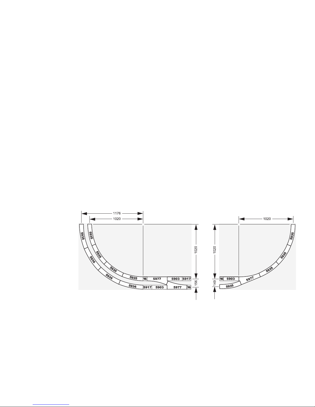
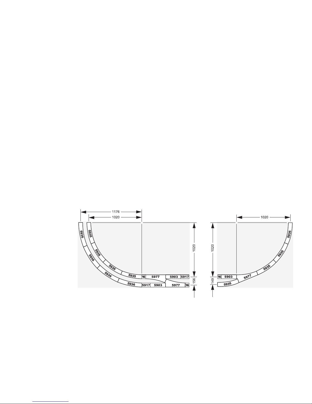
Befahrbarer Mindestradius: 1.020 mm
Mindestabstand zweier paralleler Gleise bei r
min
= 1.020 mm: 149 mm.
Bei zu geringem Abstand kann es in Kurven zu einer Kollision und damit zu Beschädigungen von aneinander vorbeifahrenden Wagen oder Loks kommen!
Page 5

5
Beleuchtung
Dieser Wagen besitzt serienmäßig eine eingebaute
LED-Beleuchtung. Diese LED-Beleuchtung ist für einen
geringen Leistungsbedarf im Digital- oder Delta-Betrieb
optimiert. Im konventionellen Betrieb (Wechselstrom
oder Gleichstrom) funktioniert diese Beleuchtung daher
erst bei sehr hohen Geschwindigkeiten der ziehenden
Lokomotive.
Wichtiger Hinweis:
Alle Radsätze des Wagens werden für die Leistungsversorgung der Beleuchtung verwendet. Die Räderseiten
beider Drehgestelle sind daher elektrisch miteinander
verbunden. Trennstellen werden somit von den Drehgestellen überbrückt. Daher kann es bei Signalen mit stromlos geschalteten Gleisabschnitten zu einem Durchfahren
des Zuges kommen, wenn der Personenwagen sich mit
einem Drehgestell im Signalabschnitt befindet.
Bitte berücksichtigen Sie, dass die Ersatzteile zu diesem
werkseitig gealterten Modell nur im nicht gealterten
Zustand verfügbar sind.
Eine Verwendung dieses Personenwagens zusammen
mit dem Bremsmodul 72441/72442 ist nur möglich, wenn
der erste Übergangsbereich die Länge des kompletten
Zuges (!) und nicht nur die Länge der längsten Lokomotive besitzt. Ein zu kurzer Übergangsbereich kann zur
Zerstörung der Control Unit führen!
Page 6
6
Umbau der Beleuchtungsplatine
Die Beleuchtungsplatine ist für den Einbau des Funktionsdecoders vorbereitet. Danach können die LEDs jeweils in der
Hälfte des Wagendurchgangs oder in der Hälfte der Abteile separat im Digital-Betrieb eingeschaltet werden.
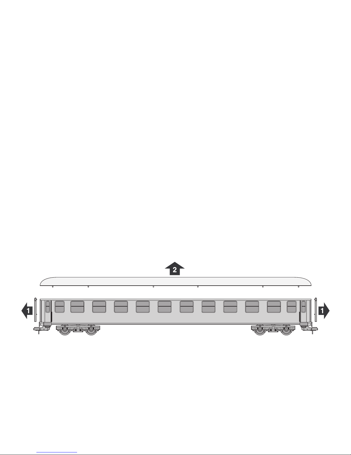
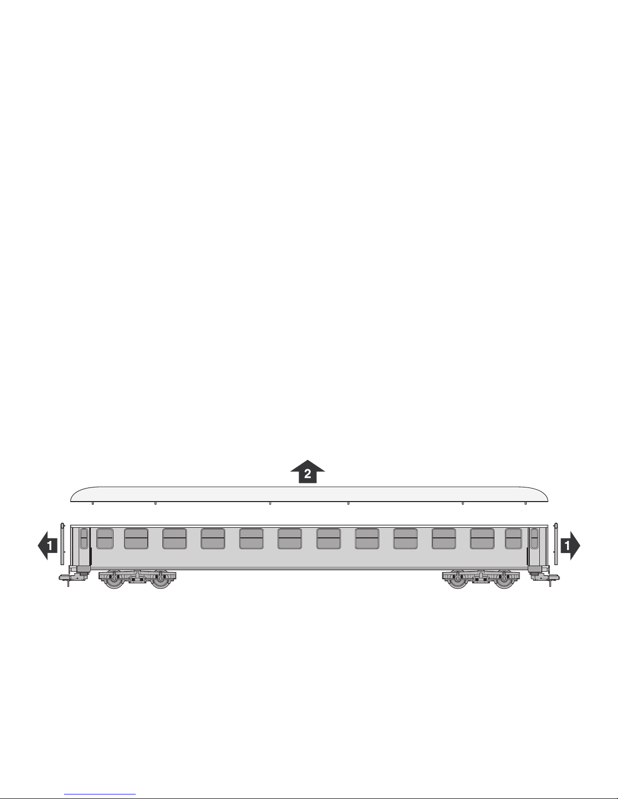
1. Wagendach entfernen
Hinweis: Das Dach besitzt mehrere recht stramm sitzende Rastverbindungen. Zum Abnehmen des Daches ist daher ein
hoher Kraftaufwand notwendig.
Page 7
7
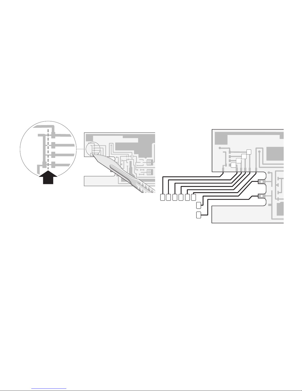
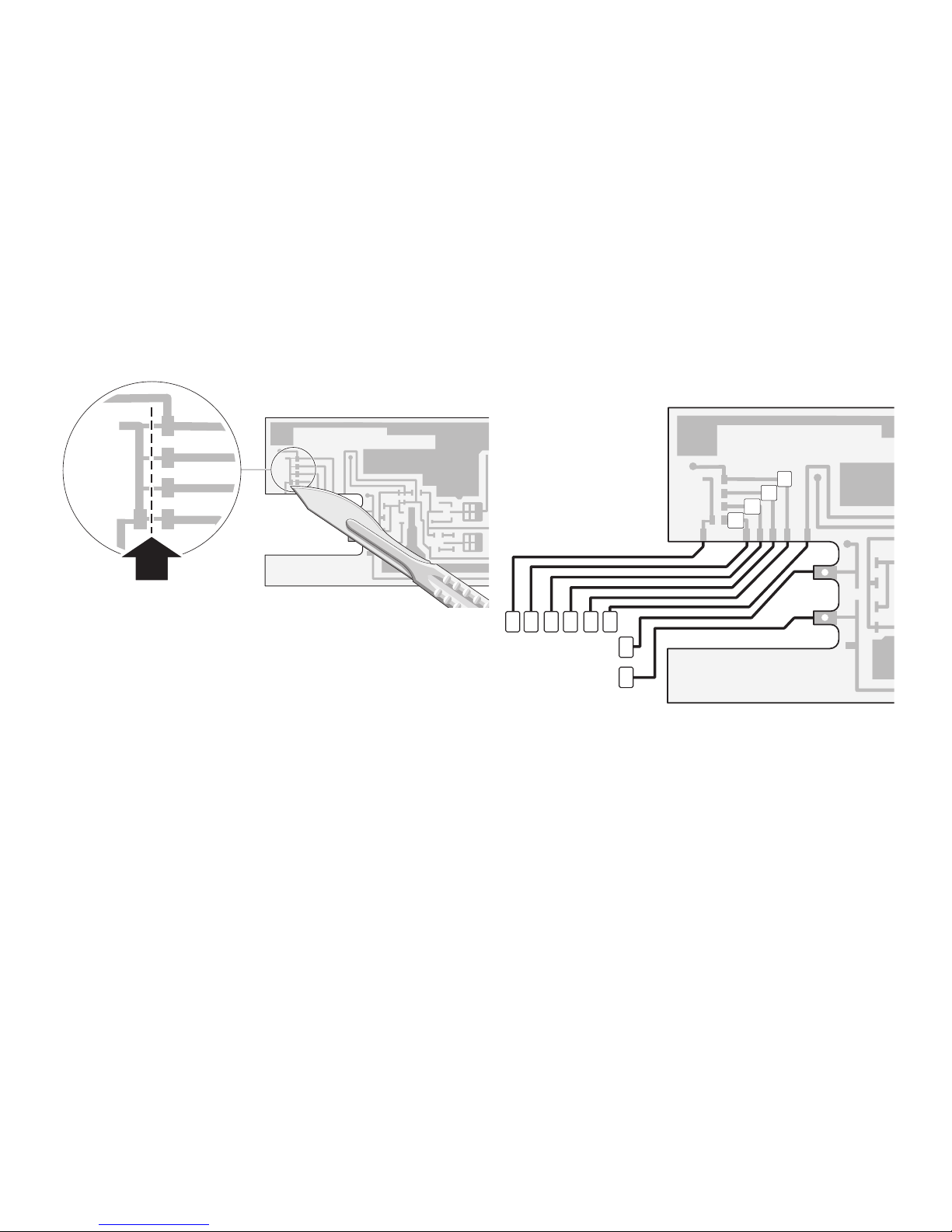
2. Leiterbahnen auftrennen
3. Decoder einsetzen
Beachten Sie bitte die Hinweise zur Codierung des Funktionsdecoders in der zugehörigen Anleitung.
8 7 6 5 4 3
2
1
f3
f4
f2
f1
f1 Beleuchtung Wagendurchgang links
f2 Beleuchtung Wagendurchgang rechts
f3 Beleuchtung Abteile links
f4 Beleuchtung Abteile rechts
1 braun 0
2 rot B
3 orange +
4 braun/rot f1
5 braun/grün f2
6 braun/weiß f3
7 braun/gelb f4
8 violett GND
Page 8
8
Technical Information
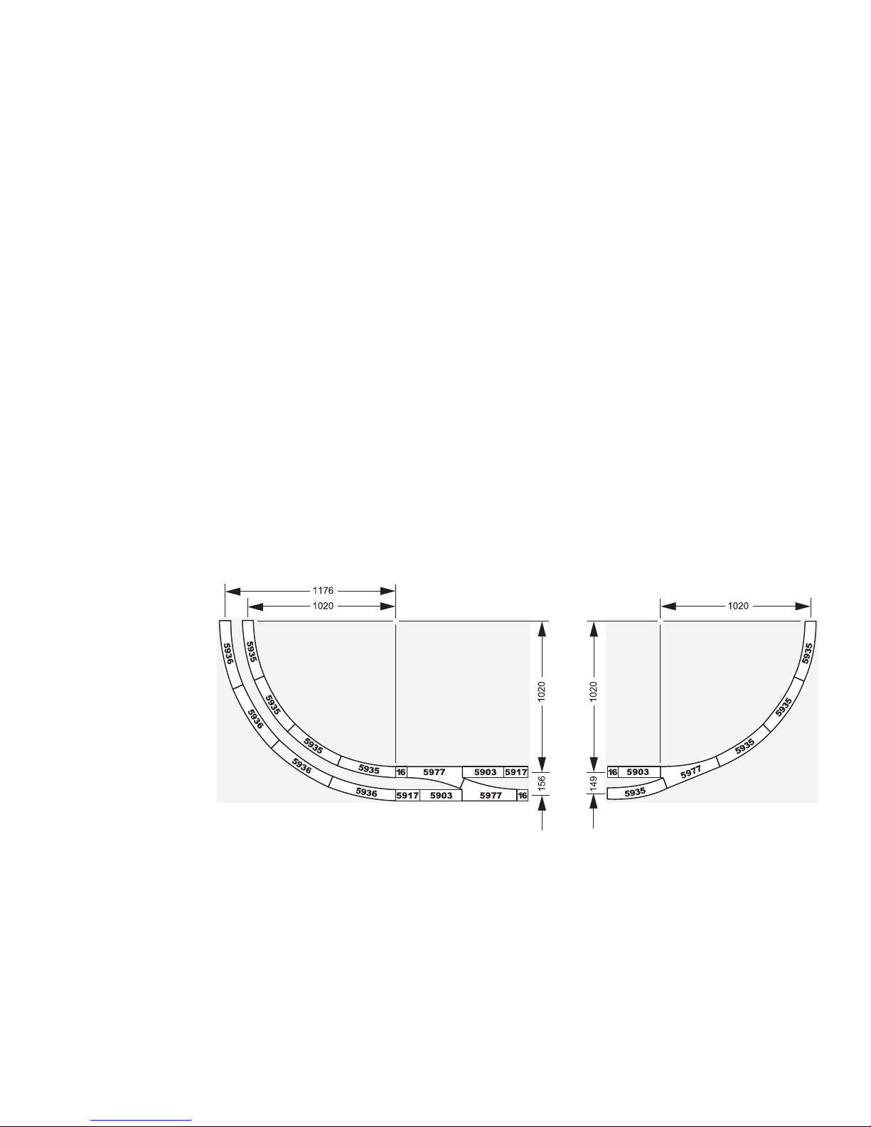
Minimum radius require for operation: 1,020 mm / 40-3/16”
Minimum spacing for two parallel tracks with the minimum radius at 1,020 mm / 40-3/16”: 149 mm / 5-7/8”.
If the spacing is too small, these cars can sideswipe each other or other cars and locomotives on curves an thus cause
damage to these cars!
Page 9

9
Lighting
These cars have built-in LED lighting that has been
installed at the factory. This LED lighting consumes very
little power and is therefore suitable for digital or Delta
operation. In conventional operation (AC or DC power)
this lighting does not begin to work until the cars are
being pulled at fairly high speeds by a locomotive.
Important:
All of the wheel sets on these cars are used for providing
power to the ligths. The wheels for both trucks are therefore electrically connected with each other. Insulated
track joints (for signal blocks, etc.) will be bridged by
these trucks. It may happen that a train will run through
a signal block, where the power has been shut off by a
signal set for stop, if these cars are in the train.
Please note that the spare parts for this model weathered at the factory are only available in non-weathered
version.
These cars can be used with the 72441/72442 brake
module only if the first transition area is the length of the
entire train (!), not the length of the longest locomotive. A
transition area that is too short may lead to the destruction of the Control Unit!
Page 10
10
Conversion of the circuit board for the lighting
The circuit board for the lighting is ready for the installation of a function decoder. With this decoder the lights in either half
of the car’s corridor or in half of the compartments can be turned on separately in digital operation.
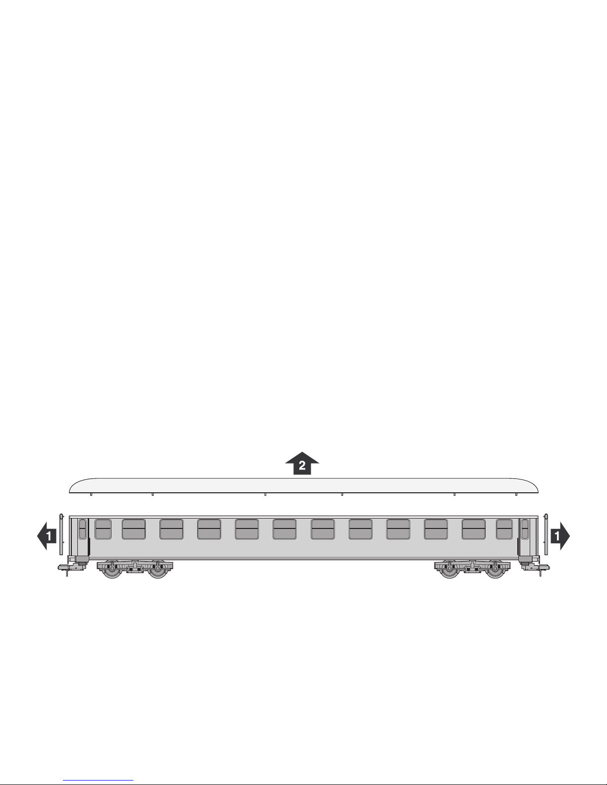
1. Remove the car roof
Important: The roof has several very rigid snap-in connections. A certain amount of force is therefore necessary to remove
the roof.
Page 11
11
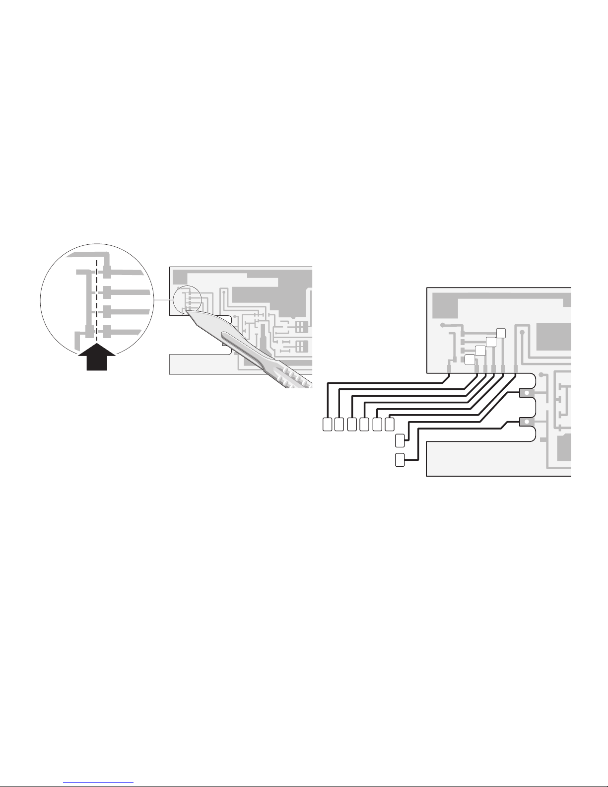
2. Cut the conductors 3. Install the decoder
Please note the directions for the coding switches on the
function decoder in the instructions that come with this
unit.
8 7 6 5 4 3
2
1
f3
f4
f2
f1
f1 Lighting in the car corridor on the left side
f2 Lighting in the car corridor on the right side
f3 Lighting in the compartments on the left side
f4 Lighting in the compartments on the right side
1 brown 0
2 red B
3 orange +
4 brown/red f1
5 brown/green f2
6 brown/white f3
7 brown/yellow f4
8 violet GND
Page 12
12
Informations techniques
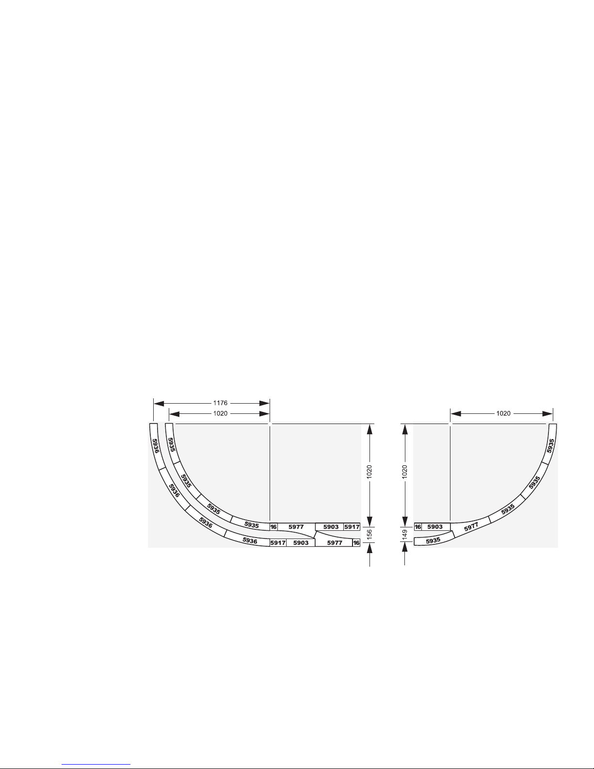
Rayon minimal d’inscription en courbe : 1.020 mm.
Entraxe minimal de deux voies parallèles de rayon min. 1.020 mm : 149 mm.
Un entraxe trop petit peut provoquer des accrochages entre véhicules se croisant et engendrer des dommages à ceux-ci!
Page 13

13
Eclairage
Cette voiture possède de série un éclairage intégré comportant des diodes lumineuses. Cet éclairage par diodes
est optimisé pour une faible consommation en courant en
mode d’exploitation Digital ou Delta. En exploitation conventionnelle (courant continu ou alternatif), cet éclairage
fonctionne surtout lorsque la locomotive remorquant la ou
les voitures roule à haute vitesse.
Remarque importante :
Tous les essieux de la voiture sont utilisés pur
l’alimentation en courant de l’éclairage. Sur chaque côté,
les roues des deux bogies sont donc reliées électriquement. Il s’ensuit que les coupures de voie peuvent être
pontées par les bogies. On peut donc s’attendre, devant
les signaux précédés d’une section de voie isolée électriquement et mise hors tension, à ce que le train passe
outre la section lorsqu’une voiture à voyageurs se trouve
avec un bogie seulement dans la section isolée.
Notez que les pièces de rechange pour ce modèle « vieilli
» en usine ne sont disponibles qu’à l’état « neuf ».
Une utilisation de cette voiture conjointement avec
le module de contrôle de ralentissement 72441/72442
n’est possible que si la première zone de transition a
une longueur égale à celle du train complet (!) et pas
seulement à celle de la plus longue locomotive. Une
section trop courte pourrait engendrer la destruction de
la Control Unit!
Page 14
14
Modification de la platine d’éclairage
La platine d’éclairage est prééquipée pour une installation du décodeur de fonctions. Il est donc possible, en exploitation
Digital, de diviser l’éclairage et de commuter séparément celui-ci dans chacune des moitiés du couloir ou des compartiments.
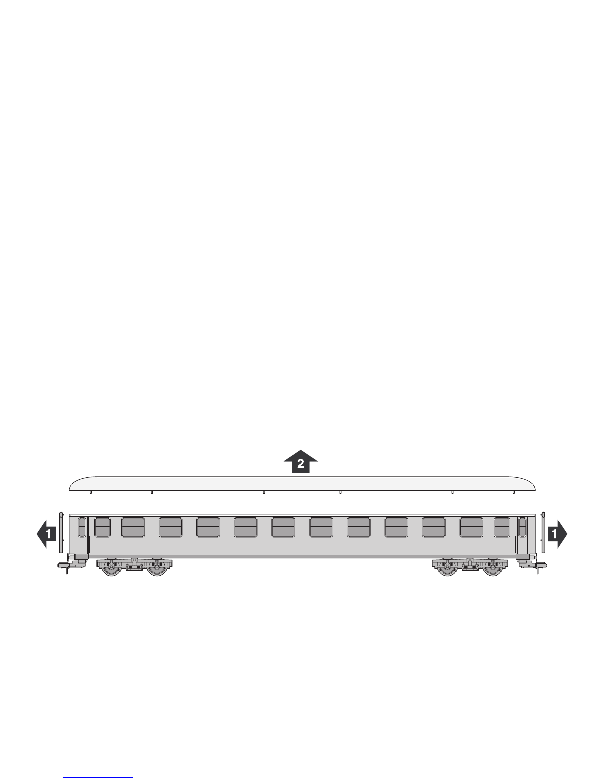
1. Enlevez la toiture de la voiture
Remarque : La toiture est fixée par plusieurs liaisons à encoches assez rigides. Pour l’enlever, il faut déployer une force
notable.
Page 15
15
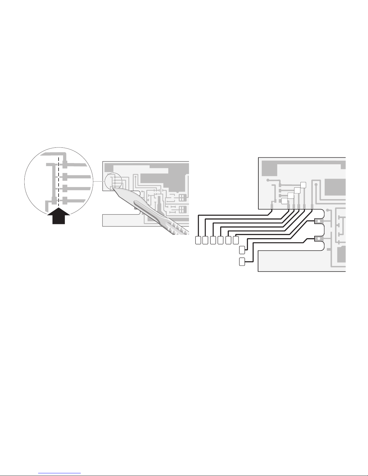
2. Séparez les pistes de courant 3. Installez le décodeur
Dans l’instruction accompagnant le décodeur, veillez à
respecter la remarque concernant le codage.
8 7 6 5 4 3
2
1
f3
f4
f2
f1
f1 Eclairage couloir de gauche
f2 Eclairage couloir de droite
f3 Eclairage compartiments de gauche
f4 Eclairage compartiments de droite
1 brun 0
2 rouge B
3 orange +
4 brun/rouge f1
5 brun/vert f2
6 brun/blanc f3
7 brun/jaune f4
8 violet GND
Page 16
16
Technische informatie
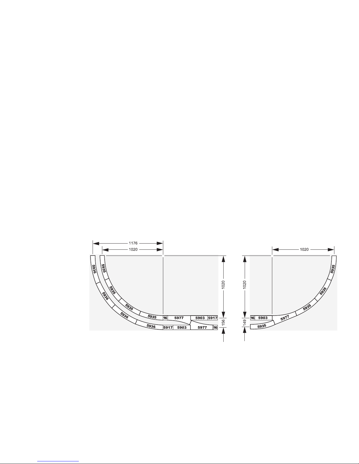
Berijdbare minimale radius: 1020 mm.
Minimale afstand tussen twee parallelle sporen bij de minimale radius van 1020 mm is: 149 mm.
Bij een te kleine afstand kan het in de bogen tot botsingen leiden tussen de elkaar voorbijrijdende rijtuigen en locomotie-
ven!
Page 17

17
Verlichting
Dit rijtuig is seriematig voorzien van een ingebouwde
LED verlichting. Deze LED verlichting is geoptimaliseerd
voor een laagstroom gebruik bij Märklin digitaal of Delta
bedrijf. Bij het gebruik op conventionele banen (wissel of
gelijkstroom) werkt deze verlichting pas bij een zeer hoge
snelheid van de trekkende locomotief.
Belangrijke opmerking:
alle wielassen van het rijtuig worden voor de stroomopname van de verlichting gebruikt. De wielzijden van beide
draaistellen zijn met elkaar verbonden. Railisolaties worden zodoende door de draaistellen overbrugd. Hierdoor
kan het gebeuren dat, bij stopsecties van o.a. seinen, den
trein doorrijdt als een rijtuig zich met één draaistel in de
stopsectie bevindt.
Wees er op bedacht dat de onderdelen voor dit model,
dat vanaf de fabriek “verouderd” is, alleen in de niet
verouderde” toestand beschikbaar zijn.
Het gebruik van deze rijtuigen in combinatie met de
afremmodule 72441/72442 is alleen dan mogelijk, als de
eerste overgangssectie de lengte heeft van de gehele
trein (!) en niet zoals gebruikelijk de lengte van de
langste locomotief. Een korter overgangssectie kan
leiden tot ernstige beschadiging van de Control Unit!
Page 18
18
Ombouwen van de verlichtingsprint
De verlichtingsprint is voorbereid voor de inbouw van de functie decoder. Na inbouw van deze functie decoder kan de
verlichting, bij digitaal bedrijf apart ingeschakeld worden, in een helft van de rijtuiggang of in een helft van de coupés.
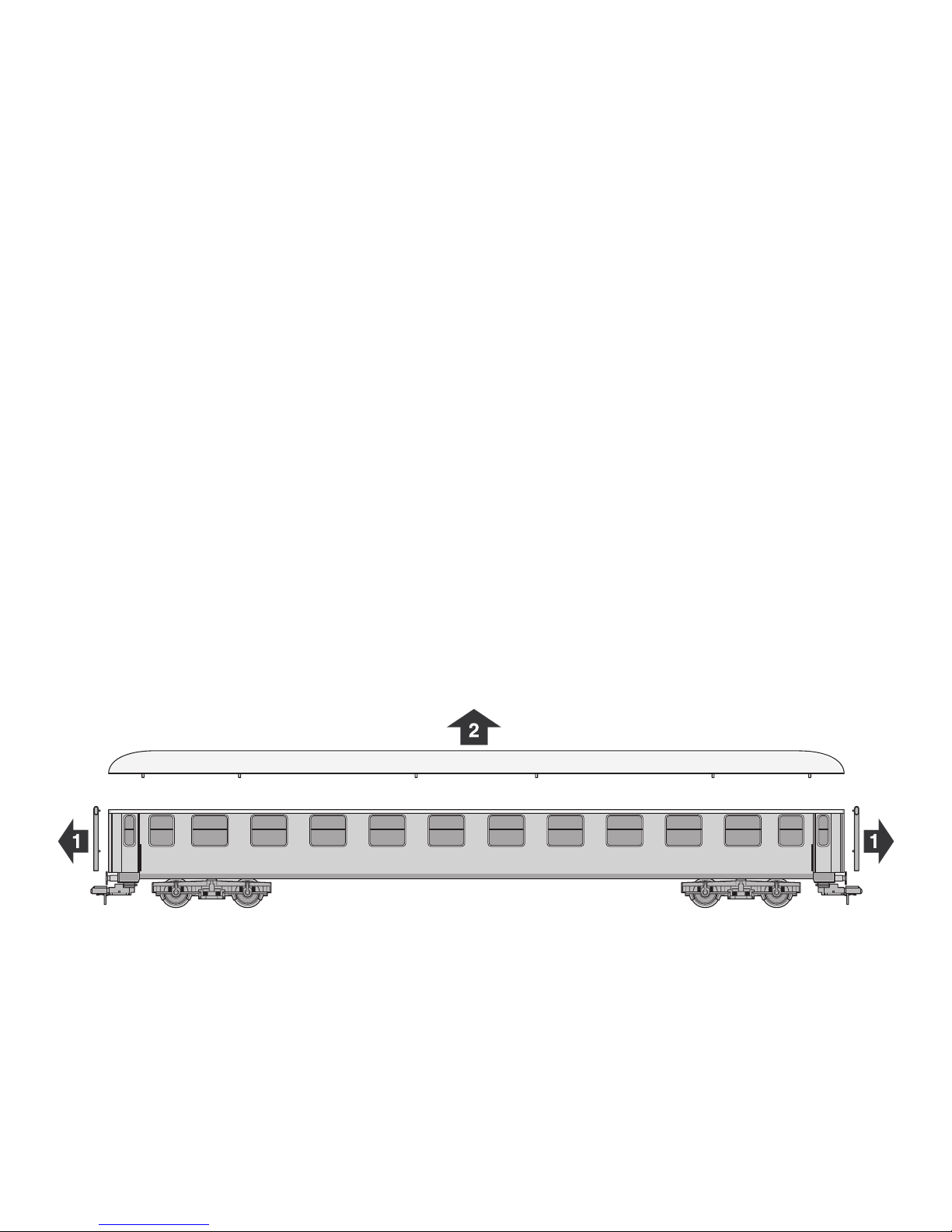
1. Dak van het rijtuig verwijderen
Opmerking: het dak zit met meerdere, strakke klikverbindingen vast. Voor het verwijderen van het dak is wat meer kracht
nodig.
Page 19
19
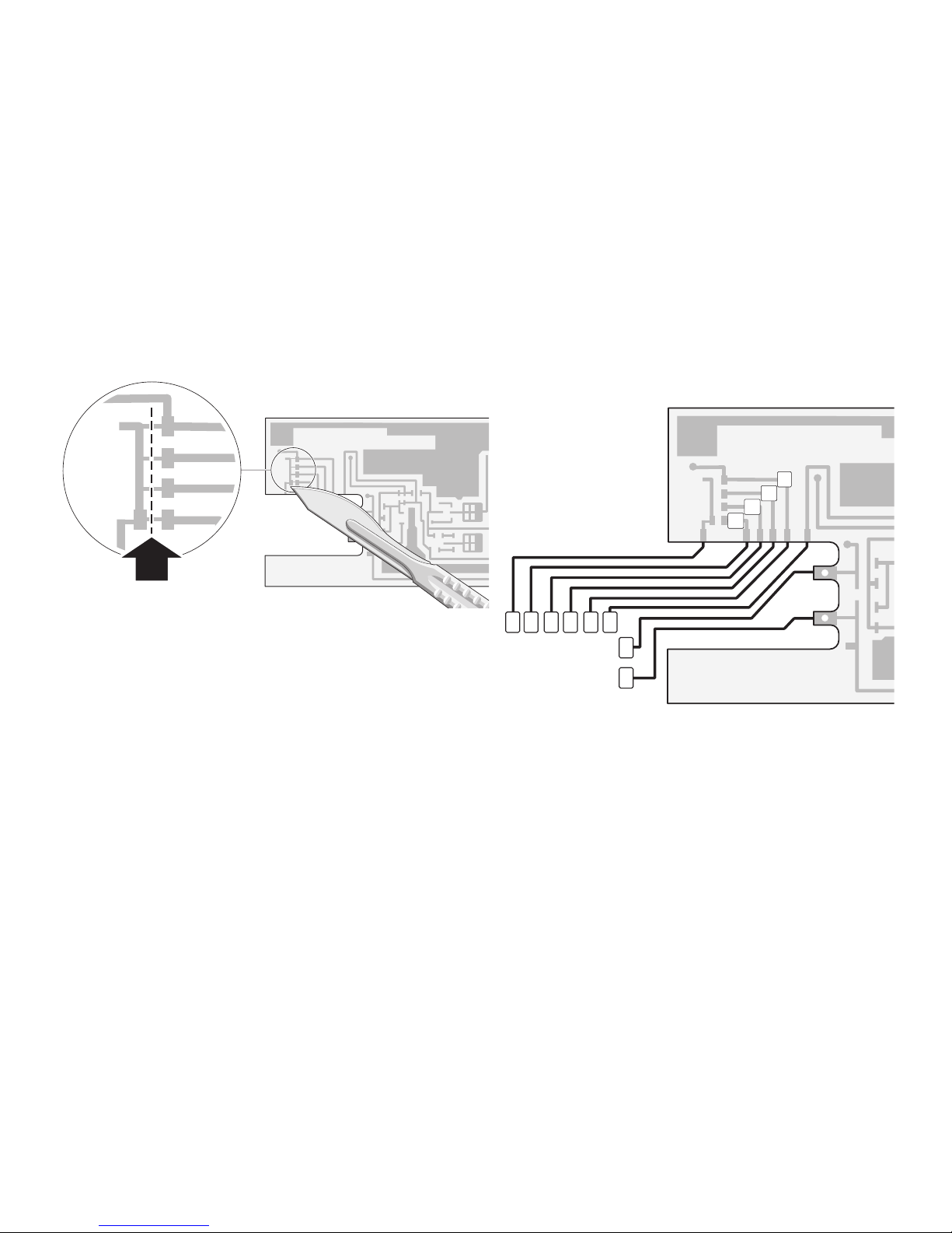
2. Banen op de print onderbreken 3. Decoder monteren
Lees a.u.b. de aanwijzingen voor het coderen van de
functie-decoder in de handleiding van de decoder.
8 7 6 5 4 3
2
1
f3
f4
f2
f1
f1 verlichting gangpad links
f2 verlichting gangpad rechts
f3 verlichting coupés links
f4 verlichting coupés rechts
1 bruin 0
2 rood B
3 orange +
4 bruin/rood f1
5 bruin/groen f2
6 bruin/wit f3
7 bruin/geel f4
8 paars GND
Page 20
20
Información técnica
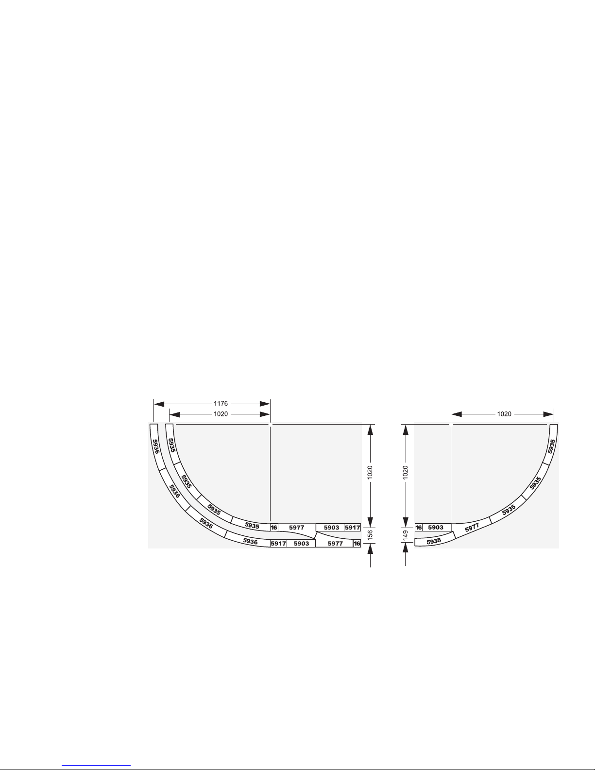
Radio mínimo describible: 1.020 mm
Distancia mínima de dos vías paralelas a rmín = 1.020 mm: 149 mm.
¡Si la distancia es demasiado baja, se puede producir una colisión en las curvas y, por tanto, daños al cruzarse dos
vagones o locomotoras!
Page 21

21
Iluminación
De serie, este vagón no dispone de iluminación por LEDs
integrada. Esta iluminación por LEDs está optimizada
para una baja demanda de potencia en funcionamiento
en modo Digital o en modo Delta. Por este motivo, en el
funcionamiento en modo convencional (corriente alterna
o corriente continua), esta iluminación solo funciona a
velocidades muy elevadas de la locomotora de arrastre.
Nota importante:
Todos los ejes montados del coche se utilizan para la
alimentación de potencia de la iluminación. Por este
motivo, los lados de las ruedas de ambos bogies están interconectados eléctricamente. De este modo, los bogies
puentean las separaciones entre tramos de vía. Por este
motivo, en señales con tramos de vía con la alimentación
eléctrica desconectada puede ocurrir que el tren siga su
marcha si el coche de viajeros se encuentra con un bogie
en el tramo de señal.
Tenga presente que los recambios correspondientes a
este modelo en miniatura envejecido en fábrica están
disponibles únicamente en versión no envejecida.
Es posible utilizar este coche de viajeros junto con el
módulo de freno 72441/72442 solo si la primera zona de
transición tiene la longitud del tren completo (!) y no solo
la longitud de la locomotora más larga. ¡Una zona de
transición demasiado corta puede provocar la destrucción de la Control Unit!
Page 22
22
Adaptación de la platina de iluminación
La platina de iluminación está preparada para instalar el decoder de funciones. Acto seguido, los LEDs se pueden
encender en cada mitad de la intercirculación entre coches o en la mitad de los compartimentos por separado en funcionamiento en Digital.
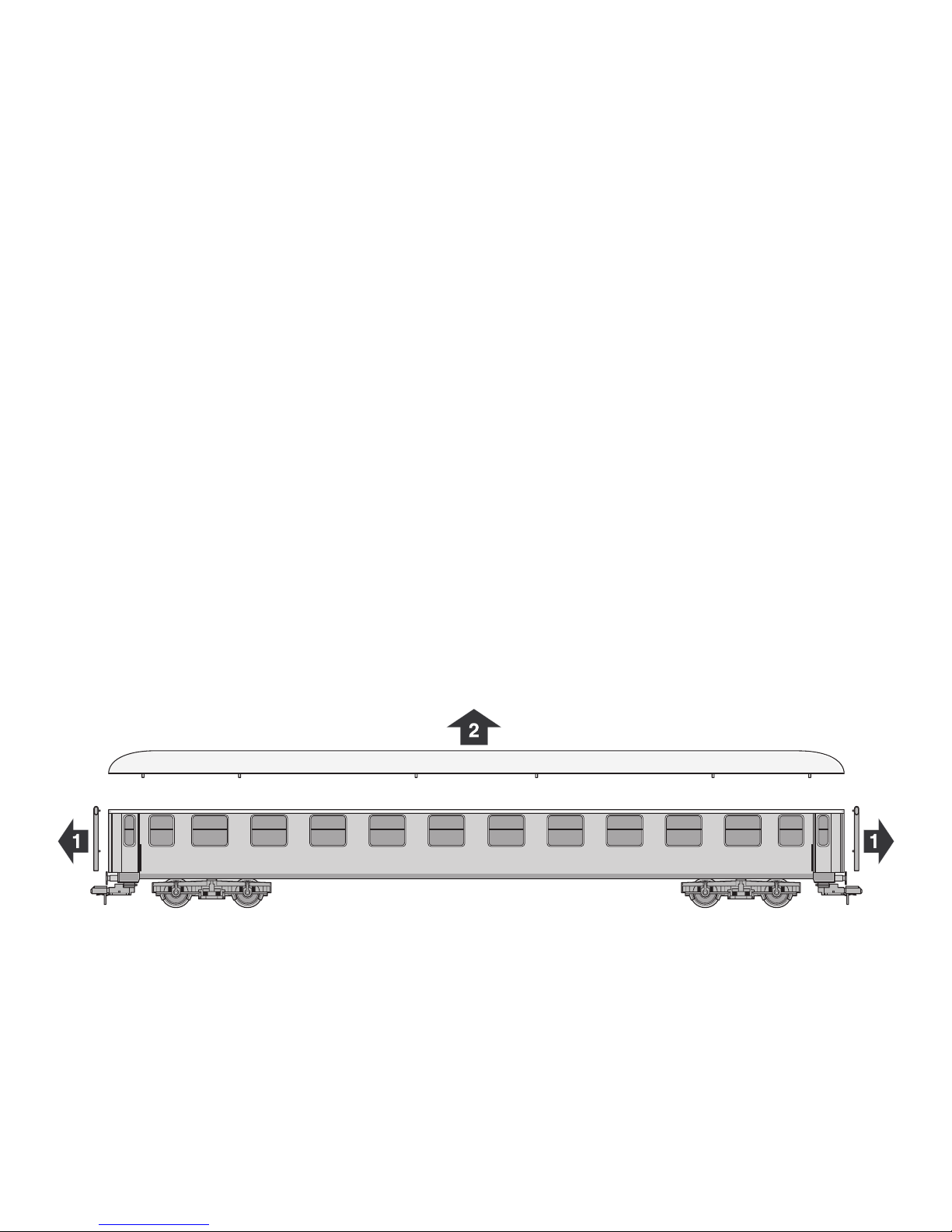
1. Desmontar el techo del coche
Nota: El techo dispone de varias uniones engatilladas difíciles de soltar. Por este motivo, para retirar el techo hay que
hacer mucha fuerza.
Page 23
23
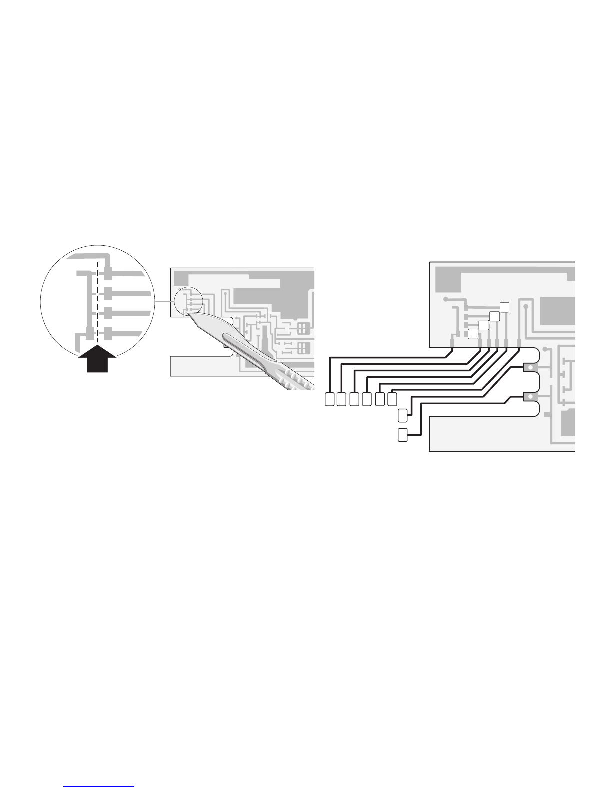
2. Separar las pistas conductoras 3. Colocar el decoder
Tener presentes las indicaciones para codificar el decoder de funciones en las instrucciones correspondientes.
8 7 6 5 4 3
2
1
f3
f4
f2
f1
f1 Iluminación de intercirculación izquierda
f2 Iluminación de intercirculación derecha
f3 Iluminación de compartimentos izquierda
f4 Iluminación de compartimentos derecha
1 marrón 0
2 rojo B
3 naranja +
4 marrón/rojo f1
5 marrón/verde f2
6 marrón/blanco f3
7 marrón/amarillo f4
8 violeta GND
Page 24
24
Informazioni tecniche
Raggio minimo percorribile: 1.020 mm
Distanza minima tra due binari paralleli con rmin = 1.020 mm: 149 mm.
In caso di una distanza troppo ridotta nelle curve si può pervenire ad una collisione e di conseguenza a danneggiamenti
delle carrozze o delle locomotive che passano una vicino all’altra!
Page 25

25
Illuminazione
Questa carrozza possiede una illuminazione incorporata
a LED montata di serie. Questa illuminazione a LED è ottimizzata per un ridotto fabbisogno di potenza nell’esercizio
Digital oppure Delta. Nell’esercizio tradizionale (corrente
alternata oppure corrente continua) funziona pertanto
solamente in presenza di velocità molto elevate della
locomotiva che traina.
Avvertenza importante:
Tutti gli assi con ruote della carrozza vengono utilizzati
per l’alimentazione di potenza dell’illuminazione. I due lati
delle ruote di entrambi i carrelli sono pertanto collegati
elettricamente tra di loro. I punti di sezionamento vengono
in tal modo scavalcati a ponte dai carrelli. Pertanto in
presenza di segnali con tratte di binario commutate
senza corrente si può arrivare ad un passaggio del treno
attraverso, quando tale carrozza passeggeri si trova con
un carrello nella tratta del segnale.
Vi preghiamo di tenere presente che le parti di ricambio
per questo modello invecchiato dalla fabbrica sono disponibili soltanto in condizioni non invecchiate.
Un utilizzo di questa carrozza passeggeri insieme con
il modulo di frenatura 72441/72442 è possibile soltanto
qualora la prima tratta di transizione possieda la lunghezza del treno completo (!) e non soltanto la lunghezza
della più lunga locomotiva. Una tratta di transizione
troppo corta può condurre al danneggiamento della
Control Unit!
Page 26
26
Modifica del circuito stampato di illuminazione
Il circuito stampato di illuminazione è predisposto per l’installazione del Decoder per funzioni. Dopodiché i LED rispettivamente nella metà del corridoio della carrozza oppure nella metà degli scompartimenti possono venire accesi separatamente nel funzionamento Digital.
1. Rimuovere il tetto della carrozza
Avvertenza: tale tetto possiede numerosi collegamenti a incastro alloggiati in modo molto stretto. Per la rimozione del tetto
è pertanto necessario l’impiego di una forza elevata.
Page 27
27
2. Tagliare le piste conduttrici 3. Installazione del Decoder
Si prega di prestare attenzione alle avvertenze per la
codifica del Decoder per Funzioni nelle allegate istruzioni.
8 7 6 5 4 3
2
1
f3
f4
f2
f1
f1 Illuminazione del corridoio sinistro della carrozza
f2 Illuminazione del corridoio destro della carrozza
f3 Illuminazione degli scompartimenti di sinistra
f4 Illuminazione degli scompartimenti di destra
1 marrone 0
2 rosso B
3 arancio +
4 marrone/rosso f1
5 marrone /verde f2
6 marrone /bianco f3
7 marrone /giallo f4
8 viola GND
Page 28
Due to different legal requirements regarding electro-magnetic compatibility,
this item may be used in the USA only after separate certification for FCC compliance and an adjustment if necessary.
Use in the USA without this certification is not permitted and absolves us of any
liability. If you should want such certification to be done, please contact us –
also due to the additional costs incurred for this.
Gebr. Märklin & Cie. GmbH
Stuttgarter Str. 55 - 57
73033 Göppingen
Germany
www.maerklin.com
259991/0715/Sm1Ef
Änderungen vorbehalten
© Gebr. Märklin & Cie. GmbH
www.maerklin.com/en/imprint.html
 Loading...