

Page 1

55892
Modell der
Baureihe 89
70-75
(pr. T3)
Page 2

Vorbild • Prototype • Exploitation dans le réel • Grootbedrijf
2
Informationen zum Vorbild
In der Zeit um 1875 beauftragte der damalige Minister für
öffentliche Arbeiten, Dr. Achenbach, die Direktion Berlin,
ihm nach Beratungen mit den übrigen Direktionen Entwürfe
vorzulegen für die Beschaffung von Lokomotiven, Personen- und Güterwagen, die als Normalien für alle Staats- und
unter Staatsverwaltung stehenden Bahnen gelten sollten.
Veröffentlicht wurden die Musterzeichnungen im Winter
1878/79.
Nach 1880 trat der Bau von Nebenbahnen in den Vordergrund. Einfach, billig, leicht und doch solide, das waren die
Forderungen, die man an solche Bahnen und ihre Betriebs
mittel stellte. So wurden im Jahre 1882 zusätzliche spezielle
Normalien für Nebenbahnen aufgestellt, welche auch eine
3/3 gekuppelte Tenderlokomotive von 29,5 t Dienstgewicht
enthielten - eben unsere erst sehr viel später so genannte T3.
Die Lokomotiven der preußischen Gattung T3 waren und
sind, trotz ihres eher unspektakulären Auftretens, auch
heute noch überaus populär. Allein die königlich Preußische
Staatsbahnen bezogen zwischen 1881 und 1910 insgesamt
1.345 Lokomotiven dieses Typs. Bei der Deutschen Reichs
bahn erhielten die T3 die Baureihen-Nummer 89, wobei die
Betriebsnummer bei 7001 begannen. Diese Nummerngruppe war das Kennzeichen für die vorgesehene baldi
ge Ausmusterung. Trotzdem konnten sich noch einzelne
Exemplare im Betrieb der Deutschen Bundesbahn bis in die
60er-Jahre hinein halten.
Information about the prototype
In the period around 1875 the Prussian minister for public works at that time, Dr. Achenbach, ordered the Berlin
Division of the Royal Prussian State Railroad to prepare for
him designs for the procurement of locomotives, passenger
and freight cars which were to be standards for all state
railroads and railroads under government admistration. The
master plans were published in the winter of 1878/ 79.
After 1880 the building of secondary lines came to the fore
in importance. Simple, inexpensive, light weight and yet
sturdy, these were the requirements that were placed on
railroads and their resource. Thus, in 1882 additional, spe
cial standards were set up for secondary lines, which also
contained a 0-6-0 coupled tank locomotive with a service
weigt of 29.5 tons - precisely our locomotive designated
much later the T3.
The Prussian class T3 locomotives were and are tremend
ously popular, despite their initially unspectacular origins.
The Royal Prussian State Railways alone ordered a total of
1,345 locomotives of this type between 1881 and 1910. On
the German State Railroad the T3 was given the classifica
-
tion number 89 with the operating numbers beginning at
7001. This number group was the designation for eminent
planned retirement. Despite this, individual examples could
still be found in service on the German FederalRailroad well
into the 1960s.
Page 3

Vorbild • Prototype • Exploitation dans le réel • Grootbedrijf
3
Informations concernant la locomotive réele
C‘est vers 1875 que le ministre des travaux publics
prussiens de l‘époque, le Dr. Achenbach, charges la
Direction de Berlin de lui soumettre, après consultation
des autres Directions, des projets pour la construction de
locoréférence pour toutes les compagnies de chemin de fer
d‘état ou se trouvant sous son égide. Les plans des modèles furent publiés au cours de l‘hiver 1878/79.
Après 1880, la construction des lignes secondaires fit
passer au premier premier plan. Simplicité. coût peu élevé,
l´gèreté mais aussi soliditè, tels étaient les critères requis por
ces lignes et leur matérial. Cést ainsi qu‘au cours de lánnèe
1882, on créa de nouveaux modèles de réfèrence supplè
mentaires pour le réseau secondaire, lesquels comportaient
une locomotive - tender accouplée 030 de 29,5 t en charge
- justement celle que lón appels bien plus tard la T3.
Les locomotives de type prussien T3 étaient et sont encore
très populaires malgré leur apparence plutôt peu spectaculaire. Les Chemins de fer Royaux Prussiens utilisèrent à eux
seuls 1.345 locomotives de ce type entre 1881 et 1910. Dans
la Deutsche reichsbahn, les T3 reçurent le numéro de série 89,
les immatriculations commençant au chiffre 7001. Ces
numéros devinrent la réfèrence de machines réformées peu
de temps après. Quelques rares exemplaires restèrent
cependant en service dans la Deutsche Bundesbahn
jusqu‘aux années 60.
Informatie van het voorbeeld
Zo rond 1875 gaf de toenmalige Pruisische minister
voor openbare werken, Dr. Achenbach, de directie Ber
lijn opdracht aan hem na overleg met de overige direties
ontwerpen voor de aanschaf van locomotieven, rijtuigen
en goederenwagens die als standaard voor alle staats- en
onder staatsbeheer staande lijnen moesten gelden, voor
te leggen. De werktekeningen werden in de winter van
1878/79 gepubliceerd.
Na 1880 kwarm de bouw van zijlijnen op de voorgrond.
Eenvoudig, licht en touch solide, dat waren de eisen die
men aan zulke banen en hun bedriijfsmiddelen stelde. Zo
werden in 1882 extra specifieke standaards voor de zijlijnen
opgesteld, die ook een gekoppelde 3/3 tenderlokomotief
van 29,5 ton dienstgewicht bevatten. Dat was onze pas
veel later zo genoemde T3.
De lokomotieven van de Pruisische soort T3 waren en zijn,
ondanks hun eerder onspectaculaire optreden, ook heden
ten dage nog ontstellend populaire. Alleen de Königlich
Preussischen Staatseisenbahnen al betrokken tussen 1881
en 1910 in totaal 1.345 lokomotiefen van dit type. Bij de
Deutsche Reichsbahn kreeg de T3 het serienummer 89,
waarbij de bedrijfsnummers bij 7001 begonnen. Deze
nummergroep was het kenmerk voor een voorziene,
spoedige buitendienststelling. Niettemin konden enkele
exemplaren bij de Deutsche Bundesbahn tot in de jaren
zestig in bedrijf blijven.
Page 4

Betrieb • Operation • Fonctionnement • Exploitatie
4
Funktion
Diese Lokomotive mit eingebauter Mehrzug-Elektronik bietet:
• Wahlweise Betrieb mit Gleichstrom (max ± 18 V=),
Wechselstrom (Märklin Transformer 32 VA), Märklin Delta
(nur Delta Station 6607), Märklin Digital (nur Control Unit)
oder Märklin Systems (Mobile Station, Central Station). Ein
Betrieb mit anderen Betriebssystemen (Impulsbreitensteuerung, Central Control 1 etc.) ist nicht möglich.
• Die Betriebsart wird automatisch erkannt.
• 80 Mehrzugadressen (davon 4 für das Delta-System)
einstellbar. Eingestellte Adresse ab Werk: 03
• Veränderbare Anfahrverzögerung (ABV).
• Veränderbare Bremsverzögerung (ABV).
• Veränderbare Höchstgeschwindigkeit.
• Einstellen der Lokparameter elektronisch über Control
Unit, Mobile Station oder Central Station.
• Eingebaute Geräuschelektronik, nur im Betrieb mit
Control Unit oder Märklin Systems nutzbar. Zusätzliche
schaltbare Geräusche.
• Eingebauter Rauchgenerator, im Märklin Systems-/Digi
-
tal- Betrieb auch ausschaltbar.
• Das Modell ist für den Betrieb auf Märklin 1-Gleisen ent
wickelt. Ein Betrieb auf anderen Gleissystemen geschieht
auf eigenes Risiko.
• Befahrbarer Mindestradius: 1020 mm
• Märklin Klauenkupplungen vorne und hinten. Bei Ver-
wendung von Kupplungssystemen anderer Hersteller
sind Betriebsprobleme nicht ausgeschlossen.
•
Bis auf die Stirnbeleuchtung und dem Rauchgenerator
sind die Funktionen in den Betriebsarten Gleichstrom,
Wechselstrom und Märklin Delta ausgeschaltet.
Die bei normalem Betrieb anfallenden Wartungsarbeiten
sind
nachfolgend beschrieben. Für Reparaturen oder
Ersatzteile wenden Sie sich bitte an Ihren Märklin-Fachhändler.
Jegliche Garantie-, Gewährleistungs- und Schadensersatzansprüche sind ausgeschlossen,
wenn in Märklin-Produkten nicht von Märklin freigegebene Fremdteile eingebaut werden
und / oder Märklin-Produkte umgebaut werden und die eingebauten Fremdteile bzw. der
Umbau für sodann aufgetretene Mängel und/ oder Schäden ursächlich war. Die Darle
gungs- und Beweislast dafür, dass der Einbau von Fremdteilen oder der Umbau in bzw. von
Märklin-Produkten für aufgetretene Mängel und / oder Schäden nicht ursächlich war, trägt
die für den Ein- und / oder Umbau verantwortliche Person und / oder Firma bzw. der Kunde.
Sicherheitshinweise
• Die Lok darf nur mit einem dafür bestimmten Betriebs-
system (Gleichstrom, Märklin Wechselstrom-Transfor
mator 6647, Märklin Delta, Märklin Digital oder Märklin
Systems) eingesetzt werden.
• Die Lok darf nur aus einer Leistungsquelle gleichzeitig
versorgt werden.
• Beachten Sie unbedingt die Sicherheitshinweise in der
Gebrauchsanleitung zu Ihrem Betriebssystem.
• Vorsicht: egal ob das Modell steht oder fährt. Nie mit
den Fingern in das Antriebsgestänge fassen. Es besteht
Quetsch- und Verletzungsgefahr!
Page 5
Betrieb • Operation • Fonctionnement • Exploitatie
5
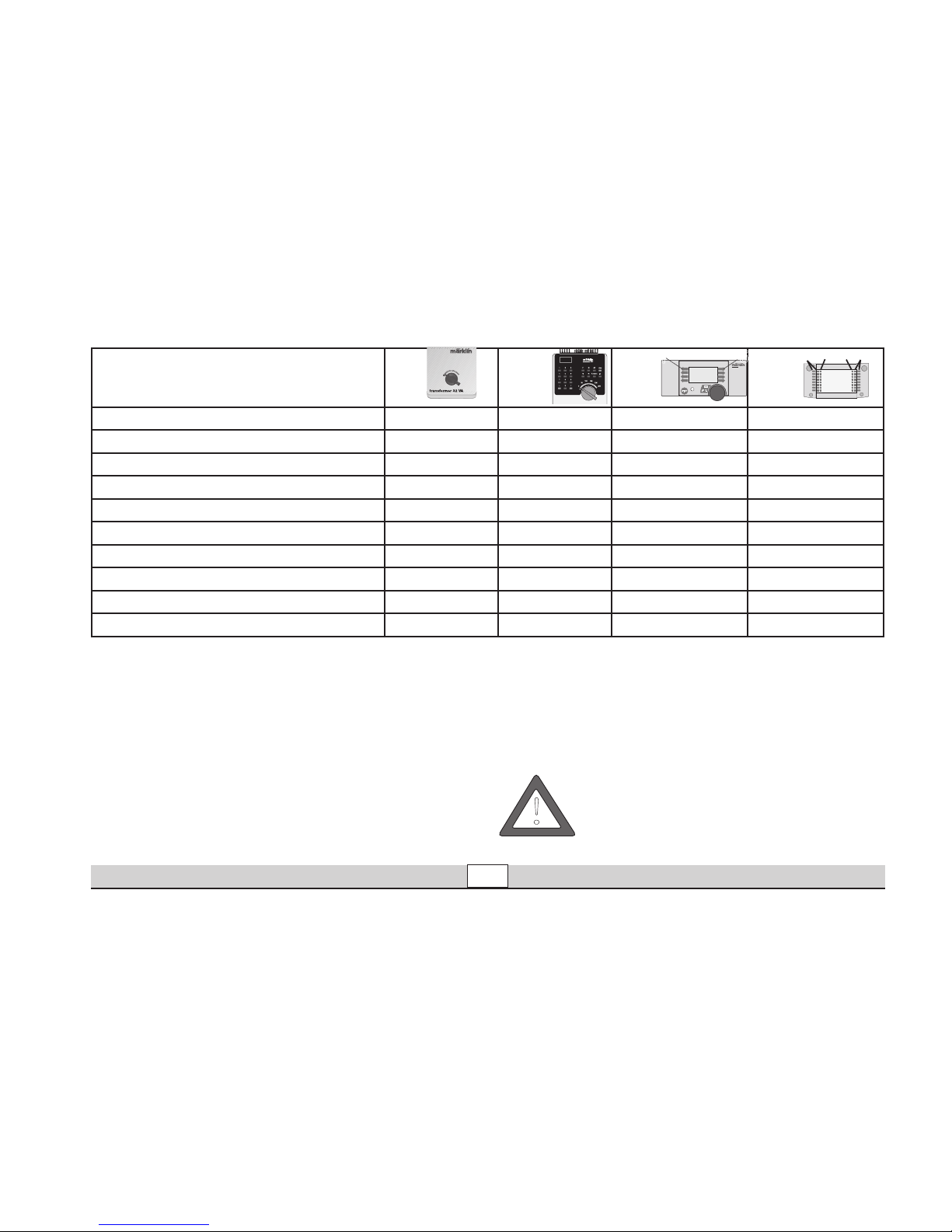
Schaltbare Funktionen
Stirnbeleuchtung fahrtrichtungsabhängig Dauernd ein
1)
function Licht-Taste Taste f0
Rauchgenerator Dauernd ein
1)
f1 Taste 7, bei Symbol Taste f1
Geräusch: Lokpfeife — f2 Taste 4, bei Symbol Taste f2
Geräusch: Dampf-Triebwerk
— f3 Taste 3, bei Symbol Taste f3
Rangiergang (nur ABV)
— f4 Taste 2, bei Symbol Taste f4
Geräusch: Glocke — — Taste 1, bei Symbol Taste f5
Geräusch: Luftpumpe — — Taste 8, bei Symbol Taste f6
Geräusch: Kohle schaufeln — — Taste 5, bei Symbol Taste f7
Geräusch: Bremsenquietschen aus
— — Taste 6, ohne Symbol Taste f8
6647
6021
60652 60212
1) => Intensität abhängig von der Höhe der Versorgungsspannung.
Vorsicht: Bei eingeschaltetem Rauchgenerator nie den
Schornstein berühren oder von oben in den Schornstein
fassen. Verbrennungsgefahr! Ein Betrieb der Lok mit eingeschaltetem Rauchgenerator von Kindern ist daher nicht
zulässig.
!
STOP
mobile station
systems
1
5
central
station
60212
f0
f0f8
f8
Page 6
Betrieb • Operation • Fonctionnement • Exploitatie
6
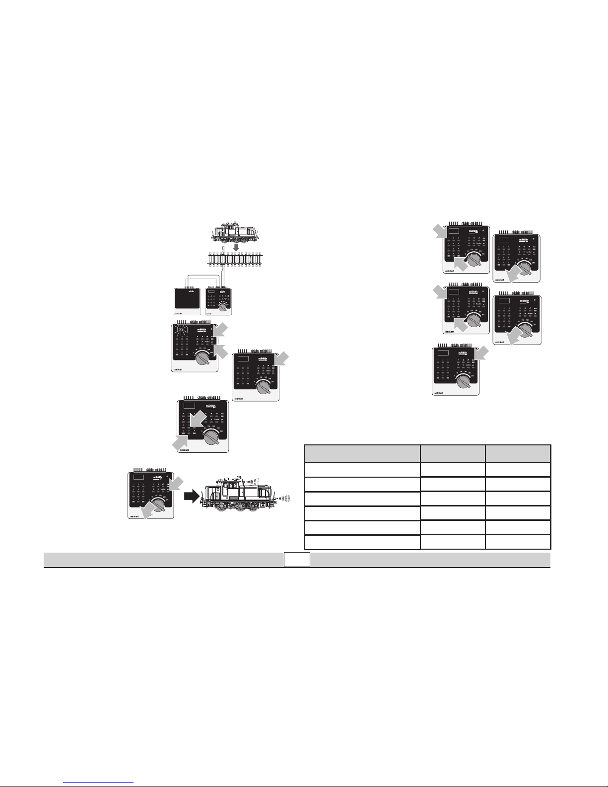
Lokparameter mit
der Control Unit einstellen
1. Voraussetzung: Aufbau
wie Grafik 1. Nur die zu
verändernde Lok ist auf
dem Gleis.
2. „Stop“- und „Go“-Taste
gleichzeitig drücken,
bis „99“ in der Anzeige
aufblinkt.
3. „Stop“-Taste drücken.
4. Lokadresse „80“ einge
-
ben.
5. Umschaltbefehl am Fahrregler dauernd
schalten. Dabei
die „Go“-Taste
drücken. => Licht
an der Lok blinkt.
Wenn nicht ab
Schritt 2 wiederholen.
6. Registernummer für den
zu ändernden Parameter
eingeben (=> Liste 1).
7. Fahrtrichtungswechsel
betätigen.
8. Neuen Wert eingeben
(=> Liste 1).
9. Fahrtrichtungswechsel
betätigen.
10. Vorgang beenden mit
Drücken der „Stop“-Tas
te.Anschließend Drücken
der „Go“-Taste.
Grafik 1
1
1
99
1
2
80
1
80
1
2
1
01
01
1
1
2
10
10
1
Liste 1: Parameter Register Wert
01 01 - 79
Adresse
03 01 - 63
Anfahrverzögerung
04 01 - 63
Bremsverzögerung
05 01 - 63
Höchstgeschwindigkeit
08 08
Rückstellen auf Serienwerte
63 01 - 63
Lautstärke
Page 7

Betrieb • Operation • Fonctionnement • Exploitatie
7
Lokparameter mit
der Mobile Station
verändern
1. Lok aus der Lokliste
auswählen.
2. Zum Untermenü „LOKÄNDERN“ wechseln.
3. Zum Untermenü
„ADRESSE“, „VMAX“,
„ACC“, „DEC“ oder
„VOL“ wechseln.
4. Neuen Wert eingeben
und übernehmen.
Beachten Sie die Hinweise
in der Anleitung zur Mobile
Station.
Lokparameter mit
der Central Station
verändern.
Beachten Sie die Hinweise
in der Anleitung zur Central
Station. Die Lok 55892 ist
in der Datenbank von der
Central Station zu finden.
Hinweis:
Beim Umprogrammieren
der Lokparameter dürfen
keine andere Lokomotiven
oder sonstige Verbraucher
von der Central Station
versorgt werden.
Page 8

Betrieb • Operation • Fonctionnement • Exploitatie
8
Function
This locomotive has a built-in multi-train electronic circuit
and offers these features:
• Optional operation with DC power (max. ± 18 volts DC),
AC power (with Märklin 32 VA transformer), with Märklin
Delta (only with the 6607 Delta Station), Märklin Digital
(only with the Control Unit), or Märklin Systems (Mobile
Station, Central Station).
• The mode of operation is automatically recognized.
• 80 multi-train addresses (4 of them for the Delta System)
can be set. Address that set at the factory: 03
• Adjustable acceleration (ABV).
• Adjustable Braking delay (ABV)
• Adjustable maximum speed.
• Setting the locomotive parameters electronically with the
Control Unit, Mobile Station or Central Station.
• Built-in sound effects circuit, can only be used in opera
tion with the Control Unit or Märklin Systems. Additional
sound effects that can be controlled.
• Built-in smoke generator, can also be turned off in Mär
-
klin Systems/Digital operation
• The model is designed for operation on Märklin 1 Gauge
track. As the consumer you assume the risk for operating
on other makes of track.
• Minimum radius for operation: 1020 mm / 40-1/6“.
• Märklin claw couplers front and rear. You may have ope
-
rations problems if you use other makes of couplers.
• Except for the headlights and the smoke generator, all
of the functions are off in the modes of operation for DC
power, AC power, and Märklin Delta.
Maintenance procedures that become necessary with
normal operation of the locomotive are described below.
Please see your authorized Märklin dealer for repairs or
spare parts.
No warranty or damage claims shall be accepted in those cases where parts neither
manufactured nor approved by Märklin have been installed in Märklin products or where
Märklin products have been converted in such a way that the non-Märklin parts or the
conversion were causal to the defects and / or damage arising. The burden of presenting
evidence and the burden of proof thereof, that the installation of non-Märklin parts or
the conversion in or of Märklin products was not causal to the defects and / or damage
arising, is borne by the person and / or company responsible for the installation and / or
conversion, or by the customer.
Safety Warnings
•
This locomotive is to be used only with an operating system designed
for it (Märklin 6646/6647 AC transformer,
Märklin Delta, Märklin Digital or Märklin Systems).
• This locomotive must never be supplied with power from
more than one transformer.
•
Pay close attention to the safety warnings in the instructions for your operating system.
• Caution: Regardless of whether model is standing still or in
motion, never grasp the drive rods and valve gear with your
fingers. You may possibly pinch and injure your fingers!
Page 9

Betrieb • Operation • Fonctionnement • Exploitatie
9
1) => Intensity dependent on the level of supply voltage.
Caution: Never touch the smoke stack or grasp the smoke
stack from above, when the smoke generator is turned
on. You may possibly burn yourself! For this reason, this
locomotive should not be operated by children, when the
smoke generator is turned on.
!
Controllable Functions
Direction-dependent headlights Always on
1)
function Headlight button
Button f0
Smoke generator Always on
1)
f1
Button 7, next to symbol Button f1
Sound effects: locomotive whistle — f2
Button 4, next to symbol Button f2
Sound effects of steam locomotive in operation — f3
Button 3, next to symbol Button f3
Low speed switching range (only with ABV) — f4
Button 2, next to symbol Button f4
Sound effect: bell — —
Button 1, next to symbol Button f5
Sound effect: air pump — —
Button 8, next to symbol Button f6
Sound effect: coal being shoveled — —
Button 5, next to symbol Button f7
Sound effect: squealing brakes off — —
Button 6, without symbol
Button f8
6647
6021
60652 60212
STOP
mobile station
systems
1
5
central
station
60212
f0
f0f8
f8
Page 10
Betrieb • Operation • Fonctionnement • Exploitatie
10
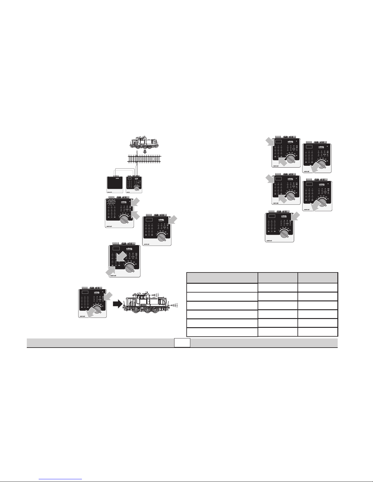
Setting Locomotive
Parameters with the
Control Unit
1. Requirement: Setup as
in diagram 1. Only the locomotive to be changed
can be on the track.
2. Press the “Stop” and
“Go” at the same time
until “99” blinks in the
display.
3. Press the “Stop” button.
4. Enter the address „80“.
5. Hold the speed control
knob in the reverse direc
tion position constantly.
Press the “Go”
button while
you do this. The
headlight on the
locomotive will
blink. If no, repeat
starting at Step 2.
6. Enter the register number
for the parameter to be
changed (=> List 1).
7. Activate the direction
reversal.
8. Enter new value
(=> List 1).
9. Activate the direction
reversal.
10. End the procedure by
pressing the “Stop”
button. Now press the
“Go” button.
Diagram 1
1
1
99
1
2
80
1
80
1
2
1
01
01
1
1
2
10
10
1
List 1: parameter Register Number
Value
01 01 - 79
Address
03 01 - 63
Acceleration delay
04 01 - 63
Braking delay
05 01 - 63
Maximum speed
08 08
Reset to series values
63 01 - 63
Volume
Page 11

Betrieb • Operation • Fonctionnement • Exploitatie
11
Changing Locomotive Parameters with
the Mobile Station
1. Select the locomotive
from the locomotive list.
2. Change to the submenu
“EDIT LOC”.
3. Change to the submenu
“ADDRESS”, “VMAX”,
“ACC”, “DEC” or „VOL“.
4. Enter the new value and
accept it into the system.
Please note the information
in the instructions for the
Mobile Station.
Changing Locomotive Parameters with
the Central Station.
Note the references and
information in the instructions
for the Central Station. The
55892 locomotive can be
found in the database for
the Central Station.
Note: When you are repro
gramming the locomotive
parameters, no other locomotive or other units can
be receiving power from the
Central Station.
Page 12

Betrieb • Operation • Fonctionnement • Exploitatie
12
Fonctionnement
Cette locomotive possède un équipement électronique
pour conduite multitrain:
•
Au choix, exploitation conventionnelle avec courant continu
(max ± 18 volts =), courant alternatif (Transformer 32 VA), exploitation avec Märklin Delta (uniquement Delta Station 6607),
Märklin Digital (uniquement Control Unit) ou Märklin Systems
(Mobile Station ou Central Station). Une exploitation avec
d’autres systèmes d’exploitation (courant à largeur d’impulsion
variable, Central Control 1, etc.) n’est pas possible.
• Le mode d’exploitation est automatiquement détecté.
• 80 adresses pour conduite multitrain (dont 4 pour le systè
-
me Delta) sont disponibles. Adresse réglée en usine: 03
• Temporisation d’accélération réglable (ABV).
• Temporisation de freinage réglable (ABV).
• Vitesse maximale réglable.
•
Réglage des paramètres de la loco électroniquement à l’aide de
la Control Unit, de la Mobile Station ou de la Central Station.
• Bruiteur électronique intégré, utilisable uniquement lors
d’exploitation avec la Control Unit ou Märklin Systems.
Bruitages complémentaires commutables.
• Générateur fumigéne intégré, également commutable en
exploitation avec Märklin Systems-/ Digital.
•
Le modèle réduit est conçu pour rouler sur des voies Märklin 1. Le
faire rouler sur des voies d’autres systèmes comporte des risques.
• Rayon minimal d’inscription en courbe: 1020 mm.
• Attelages à griffe Märklin avant et arrière. En
cas
d’utilisation d’un système provenant d’un autre fabricant,
des problèmes sont susceptibles de survenir.
•
A l’exception des feux de signalisation et le générateur fumigéne, les fonctions sont désactivées en mode d’exploitation
courant continu, courant alternatif et Märklin Delta.
Les travaux d‘entretien occasionnels à effectuer en exploitation normale sont décrits plus loin. Pour toute réparation
ou remplacement de pièces, adressez-vous à votre détail
-
lant-spécialiste Märklin.
Tout recours à une garantie commerciale ou contractuelle ou à une demande de dommages-intérêt est exclu si des pièces non autorisées par Märklin sont intégrées dans les
produits Märklin et / ou si les produits Märklin sont transformés et que les pièces d’autres
fabricants montées ou la transformation constituent la cause des défauts et / ou dommages apparus. C’est à la personne et / ou la société responsable du montage / de la
transformation ou au client qu’incombe la charge de prouver que le montage des pièces
d’autres fabricants sur des produits Märklin ou la transformation des produits Märklin
n’est pas à l’origine des défauts et ou dommages apparus.
Remarques importantes sur la sécurité
•
La locomotive ne peut être mise en service qu’avec un système
d’exploitation adéquat (Märklin courant alternatif -transformateur 6647, Märklin Delta, Märklin Digital ou Märklin Systems).
• La locomotive ne peut être alimentée en courant que par
une seule source de courant.
• Veuillez impérativement respecter les remarques sur la
sécurité décrites dans le mode d’emploi en ce qui concerne le système d’exploitation.
• Attention : que le modèle soit arrêté ou qu‘il roule,
ne jamais mettre les doigts dans le mécanisme
d‘entraînement. Risque d‘écrasement et de blessure !
Page 13
Betrieb • Operation • Fonctionnement • Exploitatie
13
1) => L’intensité est fonction de la tension d’alimentation.
Attention : ne jamais toucher la cheminée ou y insérer la
main lorsque le générateur de fumée est enclenché. Risque
de brûlure ! Par conséquent, il est interdit aux enfants
d‘utiliser la locomotive lorsque le générateur de fumée est
en marche.
!
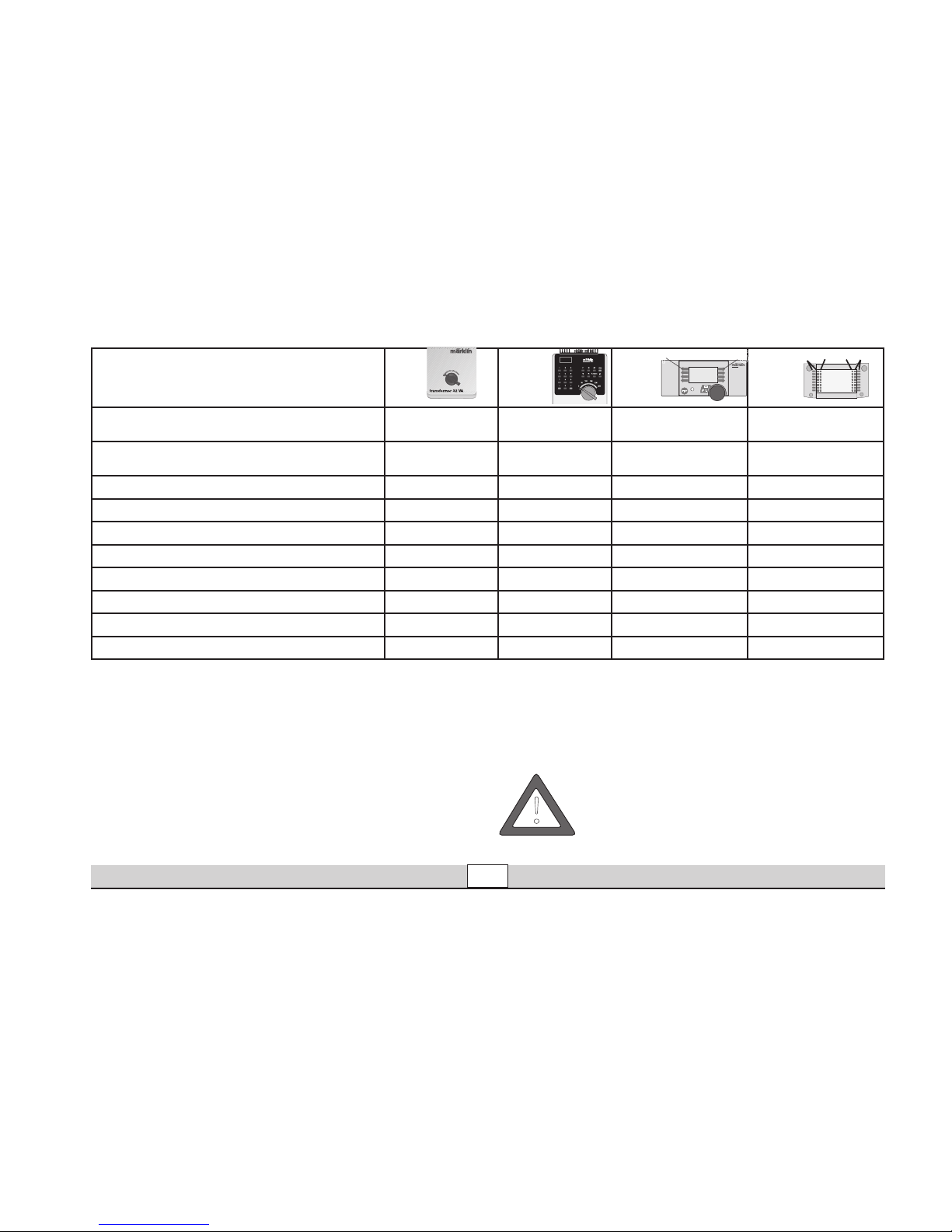
Fonctions commutables
Inversion du fanal en fonction du sens de marche
Activé en perma-
nence
1)
function Touche éclairage
Touche f0
Générateur de fumée
Activé en perma-
nence
1
f1
Touche 7, avec symbole Touche f1
Bruitage : sifflet locomotive — f2
Touche 4, avec symbole Touche f2
Bruitage : mécanisme moteur à vapeur — f3
Touche 3, avec symbole Touche f3
Vitesse de manœuvre (seulement temp. Acc./Fr) — f4
Touche 2, avec symbole Touche f4
Bruitage : cloche — —
Touche 1, avec symbole Touche f5
Bruitage : compresseur — —
Touche 8, avec symbole Touche f6
Bruitage : pelletage du charbon — —
Touche 5, avec symbole Touche f7
Bruitage : grincement de freins désactivé — —
Touche 6, sans symbole Touche f8
6647
6021
60652 60212
STOP
mobile station
systems
1
5
central
station
60212
f0
f0f8
f8
Page 14
Betrieb • Operation • Fonctionnement • Exploitatie
14
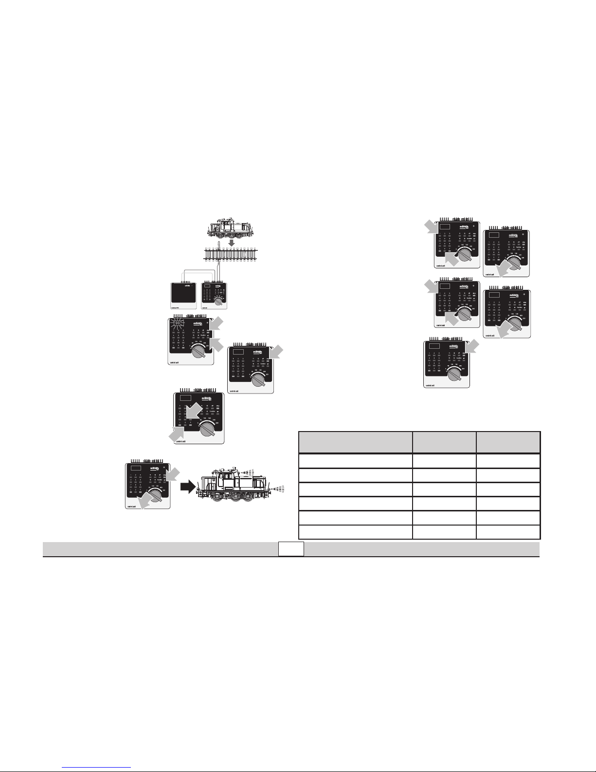
Réglage des paramètres de la loco
avec la Control Unit
1. Condition: Montage
comme sur illustration 1.
Seule la loco à modifier
peut se trouver sur la
voie.
2. Pressez simultanément
les touches „Stop“ et
„Go“ jusqu’à ce que le
nombre „99“ clignote sur
l’écran.
3. Pressez la touche „Stop“.
4. Introduisez l’adresse
„80“.
5. Tout en procédant à l’inversion
sur le régulateur,
pressez la touche
„Go“. Les feux
clignotent sur
la loco. Si ce
n’est pas le cas, répétez
l’étape 2.
6. Introduisez le numéro de
registre pour le paramèt
-
re à modifier (=> liste 1).
7. Exécutez l’inversion du
sens de marche.
8. Introduisez la nouvelle
valeur (=> liste 1).
9. Exécutez l’inversion du
sens de marche.
10. Terminez le processus
en pressant la touche
„Stop“. Ensuite, pressez
la touche „Go“.
Illustration 1
1
1
99
1
2
80
1
80
1
2
1
01
01
1
1
2
10
10
1
Liste 1: Paramètre
Numéro du
registre
Valeur
01 01 - 79Addresse
03 01 - 63
Temporisation de démarrage
04 01 - 63Temporisation de freinage
05 01 - 63Vitesse maximale
08 08
Remettre aux valeurs de série
63 01 - 63Volume haut-parleur
Page 15

Betrieb • Operation • Fonctionnement • Exploitatie
15
Modification des
paramètres de la
locomotive à l‘aide
de la Mobile Station
1. Sélectionnez la loco dans
la liste.
2. Allez au sous-menu
„MODIF LOC“.
3. Allez au sous-menu
„ADRESSE“, „VMAX“,
„ACC“, „DEC“ ou „VOL“.
4. Entrez la nouvelle valeur
et acceptez.
Respectez les remarques
mentionnées dans
l’instruction accompagnant
la Mobile Station.
Modification des paramètres de la locomotive à l‘aide de la
Central Station.
Tenir compte des remarques faites dans les instructions de la Central Station.
La locomotive 55892 se
trouve dans la banque
de données de la Central
Station.
Remarque : lors du chan
-
gement de programmati
on des paramètres de la
locomotive, aucune autre
locomotive ou aucun autre
consommateur ne doit
être alimenté par la Central
Station.
Page 16

Betrieb • Operation • Fonctionnement • Exploitatie
16
Werking
Deze loc met ingebouwde digitaalelektronica biedt u:
• Naar keuze conventioneel bedrijf (wisselstroom met de
Transformer 32 VA of gelijkstroom [max +/– 18 Volt=] ),
bedrijf met Märklin Delta (alleen het Delta Station 6607),
Märklin Digital (Control Unit) of het Märklin Systems
(Mobile Station of Central Station). Het bedrijf met rijre
gelaars van andere systemen (bijv. impulsbreedte sturing,
gebruik van de Central-Control 1 (6030) of een dergelijk
systeem) is niet mogelijk.
• Het bedrijfssysteem wordt automatisch herkend.
•
80 meertreinen-adressen (4 daarvan voor het Delta-systeem) instelbaar. Ingesteld adres vanaf de fabriek: 03
•
Instelbare optrekvertraging.
• Instelbare afremvertraging.
• Instelbare maximumsnelheid.
• Elektronische instelling van de locomotiefparameters via
de Control Unit, Mobile Station of Central Station.
• Ingebouwde geluidselektronica, alleen bruikbaar in het
bedrijf met de Control Unit of Märklin Systems. Extra
schakelbare geluiden.
• Ingebouwde rookgenerator is in het bedrijf met Märklin
Systems/Digital ook uitschakelbaar
• Het model is ontwikkeld voor het gebruik op het Märklin
Spoor 1 railsysteem. Het gebruik op een ander railsysteem geschied op eigen risico.
• Berijdbare minimumradius: 1020 mm.
• Voor en achter, Märklin klauwkoppelingen. Bij het gebruik
van koppelingssystemen van andere fabrikanten zijn
storingen niet uit te sluiten.
• Op de frontverlichting en de rookgenerator na zijn de
functies in het bedrijf met gelijkstroom, wisselstroom en
Märklin Delta uitgeschakeld.
De in het normale bedrijf voorkomende onderhoudswerkzaamheden zijn verderop beschreven. Voor reparatie of
onderdelen kunt u zich tot uw Märklin winkelier wenden.
Elke aanspraak op garantie en schadevergoeding is uitgesloten, wanneer in Märklin-producten niet door Märklin vrijgegeven vreemde onderdelen ingebouwd en / of Märklin-pro
ducten omgebouwd worden en de ingebouwde vreemde onderdelen resp. de ombouw
oorzaak van nadien opgetreden defecten en / of schade was. De aantoonplicht en de bewijslijst daaromtrent, dat de inbouw van vreemde onderdelen in Märklin-producten of de
ombouw van Märklin-producten niet de oorzaak van opgetreden defecten en / of schade
is geweest, berust bij de voor de inbouw en/of ombouw verantwoordelijke persoon en / of
firma danwel bij de klant.
Veiligheidsvoorschriften
•
De loc mag alleen met een daarvoor bestemd bedrjfssysteem (Märklin wisselstroom transformator 6647, Märklin
Delta, Märklin digitaal of Märklin Systems) gebruikt worden.
• De loc mag niet vanuit meer dan één stroomvoorziening-
gelijktijdig gevoed worden.
• Lees ook aandachtig de veiligheidsvoorschriften in de
gebruiksaanwijzing van uw bedrijfssysteem.
• Voorzichtig: ongeacht of het model stilstaat of rijdt. Nooit
met de vingers aan de aandrijfstangen komen. Er bestaat
gevaar voor kneuzingen of verwondingen!
Page 17
Betrieb • Operation • Fonctionnement • Exploitatie
17
1) => Intensiteit afhankelijk van de hoogte van de voedingsspanning.
Voorzichtig: bij een ingeschakelde rookgenerator nooit de
schoorsteen aanraken of van bovenaf in de schoorsteen
voelen. Gevaar voor brandwonden! Het is daarom niet
toegestaan om kinderen met de loc met ingeschakelde
rookgenerator te laten spelen.
!
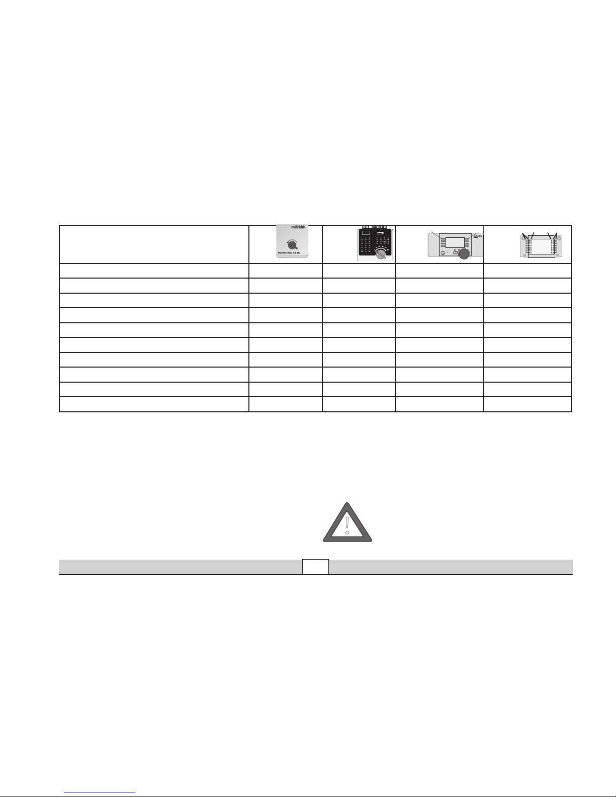
Schakelbare functies
Frontverlichting rijrichtingafhankelijk continu aan
1)
function Verlichtingstoets Toets f0
Rookgenerator continu aan
1)
f1 Toets 7, bij symbool Toets f1
Geluid: locfluit
— f2 Toets 4, bij symbool Toets f2
Geluid: stoomaandrijving — f3 Toets 3, bij symbool Toets f3
Rangeerstand (alleen optrek- afremvertraging)
— f4 Toets 2, bij symbool Toets f4
Geluid: luidklok — — Toets 1, bij symbool Toets f5
Geluid: luchtpomp — — Toets 8, bij symbool Toets f6
Geluid: kolenscheppen — — Toets 5, bij symbool Toets f7
Geluid: piepende remmen uit
— —
Toets 6, zonder symbool
Toets f8
6647
6021
60652 60212
STOP
mobile station
systems
1
5
central
station
60212
f0
f0f8
f8
Page 18
Betrieb • Operation • Fonctionnement • Exploitatie
18
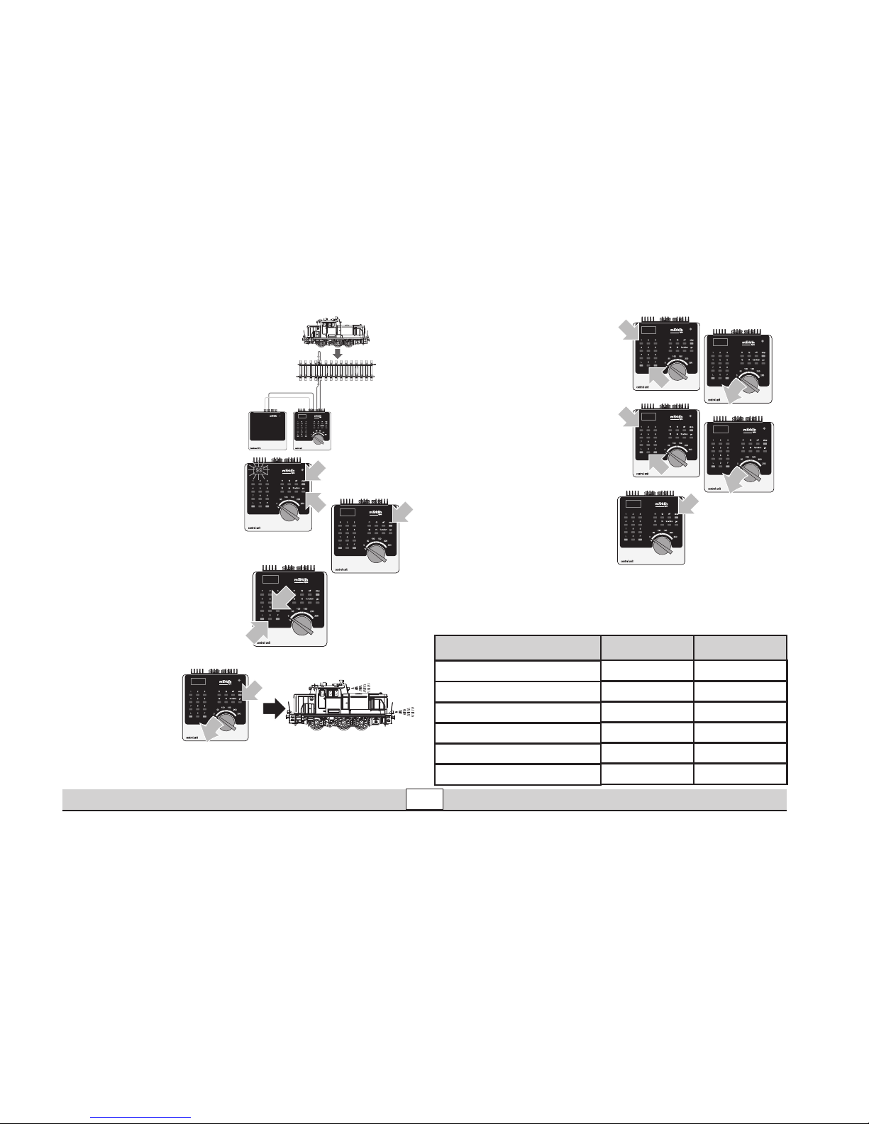
Locparameters instellen met de Control Unit
1. Voorwaarde: opbouw
zoals tekening 1. Alleen
de loc die gewijzigd moet
worden op de rails.
2. ”Stop”- en ”Go”-toets
gelijktijdig indrukken
tot ”99” in het display
oplicht.
3. ”Stop”-toets indrukken.
4. Adres „80“ invoeren.
5. Omschakelcommando
met de rijregelaar continu
bedienen. Daarbij
de ”Go”-toets
indrukken. De
verlichting van de
loc knippert. Als
dit niet het geval
is, vanaf stap 2 herhalen.
6. Het registernummer van
de te wijzigen parameter
invoeren (=> lijst 1).
7. Rijrichtingomschakeling
bedienen.
8. Nieuwe waarde invoeren
(=> lijst 1).
9. Rijrichtingomschakeling
bedienen.
10. Programmering beëin
digen door het indrukken
van de ”Stop”-toets.
Aansluitend de ”Go”-toets indrukken.
Tekening 1
1
1
99
1
2
80
1
80
1
2
1
01
01
1
1
2
10
10
1
Liste 1: Parameter
Registernummer
01 01 - 79
Adres
03 01 - 63
Optrekvertraging
04 01 - 63
Afremvertraging
05 01 - 63
Maximumsnelheid
08 08
Terugzetten naar serie-instellingen
63 01 - 63
Volume
Waarde
Page 19

Betrieb • Operation • Fonctionnement • Exploitatie
19
Locparameter met
het Mobile Station
wijzigen
1. Loc uit de loclijst kiezen.
2. Ga naar het nevenmenu
”WYZIG LOC”.
3. Ga naar het nevenme
nu ”ADRES”, ”MAX.
SNELH.”, „VOL“, ”OPTREKKEN” of ”AFREMMEN”.
4. Nieuwe waarde invoeren
en overnemen.
Neem ook de aanwijzingen
in de gebruiksaanwijzing
van het Mobile Station in
acht.
Locparameter met
het Central Station
wijzigen.
Neem de aanwijzingen in de
gebruiksaanwijzing van het
Central Station in acht. De
loc 55892 is aanwezig in de
databank van het Central
Station.
Opmerking: bij het ompro
grammeren van de locparameter mogen geen andere
locomotieven of andere
verbruikers door het Central
Station van stroom worden
voorzien.
Page 20

Betrieb auf der Anlage • Operation on a layout Exploitation sur réseau • Bedrijf op een modelbaan
20
Anschluss der Gleisanlage
Um Spannungsverluste auf
der Anlage zu vermeiden ist
immer auf gutes Zusammenpassen der Schienenverbindungslaschen zu achten.
Alle 2 bis 3 m ist eine neue
Stromeinspeisung über die
Anschlussklemmen 5654
empfehlenswert.
Befahren von Steigungen
Im Gegensatz zum Vorbild
können mit einer Modellbahn
auch größere Steigungen
befahren werden. Im Normal
fall sollte eine Steigung bei
maximal 3 Prozent liegen. Im
Extremfall sind bei ent
sprechend eingeschränkter
Zugleistung maximal 5 Pro
zent möglich. Der Anfang und
das Ende der Steigung sind
auf jeden Fall auszurunden.
Der Unterschied in der
Steigung zwischen zwei
mindestens 300 mm langen
Gleisstücken darf maximal 1
bis 1,5 Prozent betragen.
Connections between
the track layout and the
transformer
Rail joiners must fit well on the
rails of the track to which they
are joined to avoid voltage drop
on the layout. We recommend
that you install feeder wires
every 2 to 3 meters (7 to 10 feet)
using the 5654 feeder clips.
Operating the locomotive on grades
In contrast to the prototype
a locomotive on a model railroad can operate up steeper
grades. As a general rule a
grade should be no steeper
than 3%. In extreme situations
a maximum grade of 5% is
permissible, keeping in mind
that the locomotive’s tractive
effort will be less. The begin
ning and the end of the grade
must always work gradually
up to maximum grade for the
route. The maximum allowable
difference in grade between
two track sections, each with
a minimum length of 300 mm
(11-3/4“) is 1 to 1.5 percent.
Connexion des voies
ferrées
Pour éviter des pertes de potentiel sur l’installation, il faut
veiller à ce que les éclisses
de liaison des rails soient toujours parfaitement adaptées.
Une nouvelle alimentation
électrique est conseillée tous
les 2 à 3 m au moyen des
griffes d’alimentation 5654.
Franchissement des côtes
Contrairement à l’original, la
maquette est également en
mesure de franchir des côtes
assez importantes. En temps
normal, une côte devrait étre
de l’ordre de 3% maximum.
A l’extrême limite, 5% sont
envisageables avec une
puissance du train réduite en
consequence. Le début et la fin
de la côte doivent en tous cas
étre arrondis.
La différence de pente entre
deux éléments de voie d’au
moins 300 mm de longueur doit
étre de 1 à 1,5% maximum.
Aansluiting van de
sporen
Om spanningsverlies op de
modelbaan te voorkomen
moeten de raillassen altijd goed
op elkaar aansluiten. Om de 2 à
3 meter moet de voeding opni
euw op de rails gezet worden.
Daarbij zijn de aansluitklemmen
5654 aan te raden.
Berijden van hellingen
In tegenstelling tot het grote
voorbeeld kunnen met een
modelbaan ook grotere hellingen bereden worden. Normaal
moet een helling maximaal 3
procent zijn. In extreme ge
vallen is maximaal 5 procent
mogelijk, maar dan moet
rekening gehouden worden
met een evenredig verlies aan
vermogen. Het begin en het
einde van de helling moeten
altijd gerond worden.
Het verschil in de helling
tussen twee tenminste 300
mm lange railstukken mag
maximaal 1 à 1,5 procent
bedragen.
Page 21

Wartung • Maintenance • Entretien • Onderhoud
21
Gehäuses entfernen
Removing the body
Retirer le boîtier
Huis verwijderen
4.
3.
5.
5.
6.
1.
1.
1.
2.
Page 22
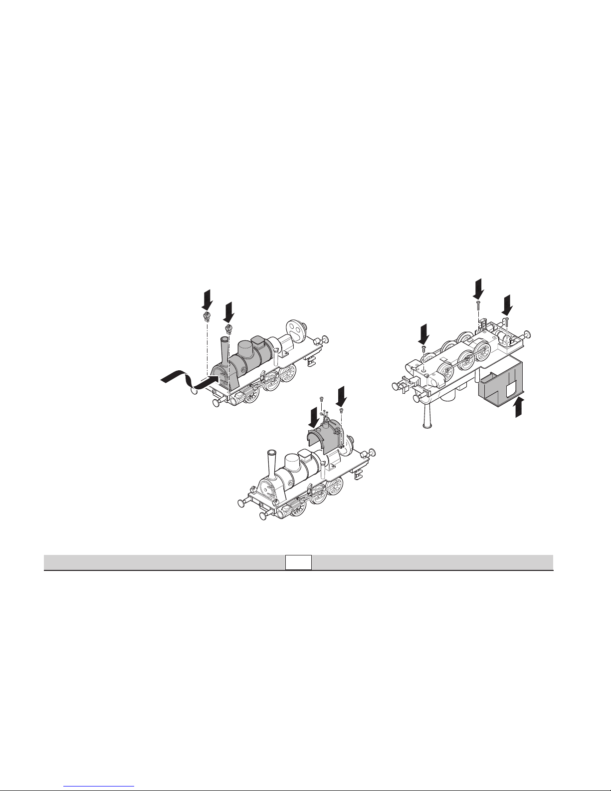
Wartung • Maintenance • Entretien • Onderhoud
22
2.
2.
1.
3.
4.
6.
6.
6.
5.
Gehäuse aufsetzen
Installing the body
Installer la caisse
Kap monteren
Page 23

Wartung • Maintenance • Entretien • Onderhoud
23
Figuren einkleben
Gluing figures in place
Coller les figurines
Figuren vastlijmen
Rauchpatrone wechseln
Changing the smoke generator
Remplacer la cartouche fumigène
Rookgenerator vervangen
1.
2.
1.
4.
5.
3.
6.
4.
5.
3.
6.
Page 24
Wartung • Maintenance • Entretien • Onderhoud
24
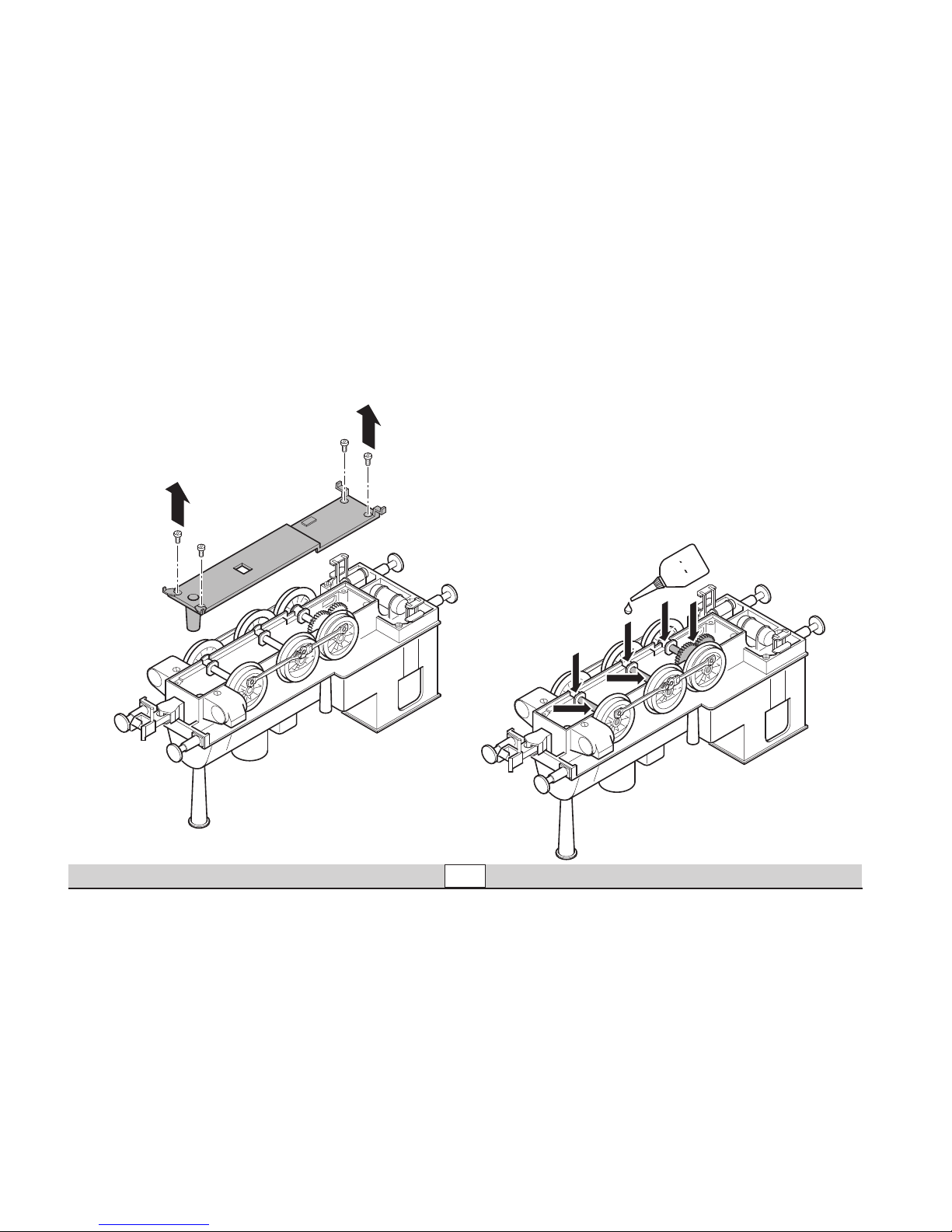
Schmierung nach 40 Betriebsstunden
Lubrication after 40 hours of operation
Graissage après 40 heures d’exploitation
Smeren na 40 bedrijfsuren
7149
marklin
Page 25

Wartung • Maintenance • Entretien • Onderhoud
25
Schleifer wechseln
Changing pick-up shoes
Remplacement des frotteurs
Nieuwe sleepcontacten aanbrengen
2.
1.
8.
7.
5.
4.
3.
6.
421 570
Page 26
Wartung • Maintenance • Entretien • Onderhoud
26
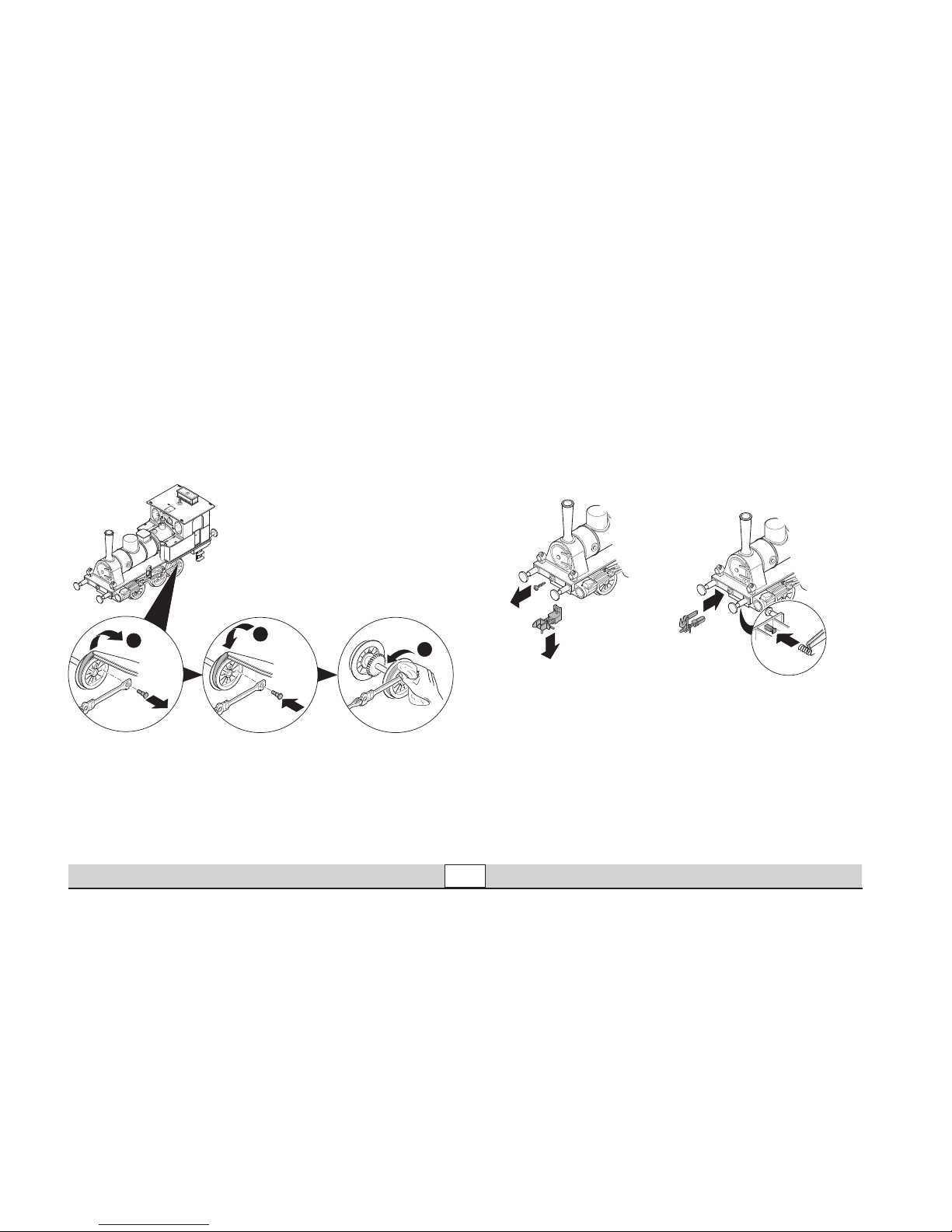
Haftreifen wechseln
Changing traction tires
Remplacer bandages
Antislipband vervangen
2.
1.
3.
4.
5.
451 039
Kupplung austauschen
Changing couplings
Remplacement des chrochets d’attelages
Koppelingen verwisselen
2.
4.
1.
5.
56101
Page 27

Wartung • Maintenance • Entretien • Onderhoud
27
Pflegehinweis
Diese Lok kann auch im
Außenbereich eingesetzt
werden. Ein Betrieb bei
schlechten Witterungsbedingungen (Schnee oder
Regen) wird nicht empfohlen.
Antrieb und Elektronik sind
gegen Spritzwasser geschützt. Wasserdurchfahr
-
ten sind nicht möglich.
Es wird empfohlen, das
Modell nach dem Betrieb
im Außenbereich auf Verschmutzung zu prüfen und
gegebenenfalls trocken mit
Staubtuch oder Pinsel zu
reinigen. Nie die Lok unter
fließendem Wasser reinigen.
Hinweis: Reinigungsmittel
können die Farbgebung
oder die Beschriftung der
Lok angreifen und beschä
-
digen.
Remarque sur
l’entretien
Cette locomotive peut également être mise en service
à l’air libre. Une utilisation
par mauvais temps (neige
ou pluie) n’est pas recom
-
mandée.
Le moteur et l’électro-ni
que sont protégés contre
les projections d’eau. Des
trajets dans l’eau ne sont
pas possibles.
Il est recommandé de
vérifier l’encrassement du
modèle après une utilisation à l’extérieur et, le cas
échéant, de nettoyer le
modèle à l’aide d’un chiffon
doux ou un pinceau. Ne
jamais nettoyer le modèle
au jet d’eau.
Attention: Certains solvants
et produits d’entretien peu
vent altérer le marquage et
la peinture du modèle.
Tips For The Care Of
Your Locomotive
This locomotive can also
be used outdoors. We do
not recommend running the
locomotive in bad weather
(snow or rain).
The mechanism and the
electronic circuit are protec
ted against spraying water.
The locomotive cannot be
run through water.
We recommend that you
check the locomotive over
after running in outdoors
and that you dry it with
a cloth or clean in with a
brush if necessary. Never
clean the locomotive with
running water.
Important: Cleaning fluids
can attack the finish and
lettering for the locomotive
and damage them.
Opmerkingen voor
het onderhoud
Deze loc kan ook buiten gebruikt worden. Het gebruik
bij slecht weer (sneeuw of
regen) is niet aan te raden.
Aandrijving en elektronica
zijn weliswaar afgeschermd
tegen spatwater maar
rijden door het water is niet
mogelijk.
Het is aan te bevelen het
model na het gebruik buiten
te controleren op vuil en dit
eventueel droog te verwijderen met een stofdoek of
een zachte kwast. Nooit de
loc onder stromend water
reinigen.
Opmerking: reinigings
middelen kunnen de lak en
de opschriften op de loc
aantasten en beschadigen.
Page 28
Wartung • Maintenance • Entretien • Onderhoud
28
31
37
39
48
49
69
70
80
81
82
83
84
85
87
88
88
86
31
36
33
37
39
38
48
49
50
52
51
60
61
62
67
67
69
76
78
78
79
83
35
63
64
72
72
73
7
8
15
14
13
11
12
1
3
2
5
5
6
9
17
19
19
25
21
20
22
28
27
26
32
32
32
33
36
35
40
41
41
42
43
44
45
54
55
56
57
58
66
79
10
16
18
24
25
23
29
64
4
30
33
33
34
34
36
36
38
46
53
52
59
68
68
71
77
78
78
74
72
72
47
75
65
Page 29

Wartung • Maintenance • Entretien • Onderhoud
29
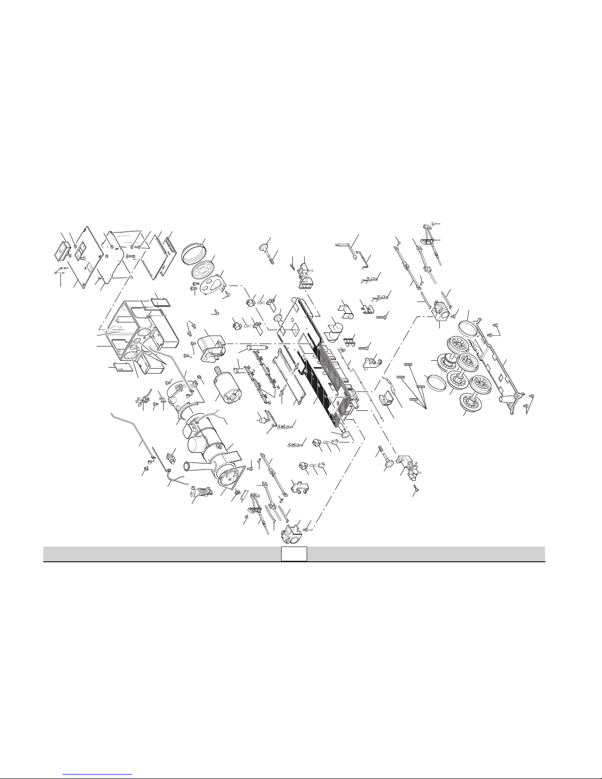
1 Führerhaus 107 840
mit
2 Tür links 433 990
3 Tür rechts 435 270
4 Fenster groß 354 520
5 Fenster klein 354 540
6 Dach 411 369
7 Lüfter —
8 Mutter 650 199
9 Pfeife 208 602
10 Vorhanghalter 106 581
mit
11 Leiterplatte Schnittstelle 102 404
12 Decoder 105 461
13 Zylinderschraube 784 800
14 Isolierung 400 089
15 Mutter 757 070
16 Senkschraube 756 100
17 Stehkessel 421 820
mit
18 Sicherheitsventil 397 550
19 Feder 397 850
20 Kessel 107 651
mit
21 Sandfallrohr links 353 880
22 Sandfallrohr rechts 353 870
23 Speiseleitung links 397 610
24 Speiseleitung rechts 353 930
25 Handrad 472 800
26 Handrad 470 830
27 Luftpumpe 470 840
28 Lichtmaschine —
29 Rauchkammertür 411 187
30 Nummernschild 107 653
31 Zylinderschraube 650 393
32 Zylinderschraube 785 350
Lok-Unterteil
33 Laterne 209 083
34 Laternenkonsole vorn 353 240
35 Laternenkonsole hinten 421 750
36 LED 503 004
37 Puffer flach 761 730
38 Puffer gewölbt 761 740
39 Druckfeder 765 660
40 Lautsprecher 508 610
41 Schraube 588 250
42 Halter 411 365
43 Gehäuse 410 053
44 Schraube 588 230
45 Wassereinfüllstutzen 411 145
Page 30
Wartung • Maintenance • Entretien • Onderhoud
30
31
37
39
48
49
69
70
80
81
82
83
84
85
87
88
88
86
31
36
33
37
39
38
48
49
50
52
51
60
61
62
67
67
69
76
78
78
79
83
35
63
64
72
72
73
7
8
15
14
13
11
12
1
3
2
5
5
6
9
17
19
19
25
21
20
22
28
27
26
32
32
32
33
36
35
40
41
41
42
43
44
45
54
55
56
57
58
66
79
10
16
18
24
25
23
29
64
4
30
33
33
34
34
36
36
38
46
53
52
59
68
68
71
77
78
78
74
72
72
47
75
65
Page 31

Wartung • Maintenance • Entretien • Onderhoud
31
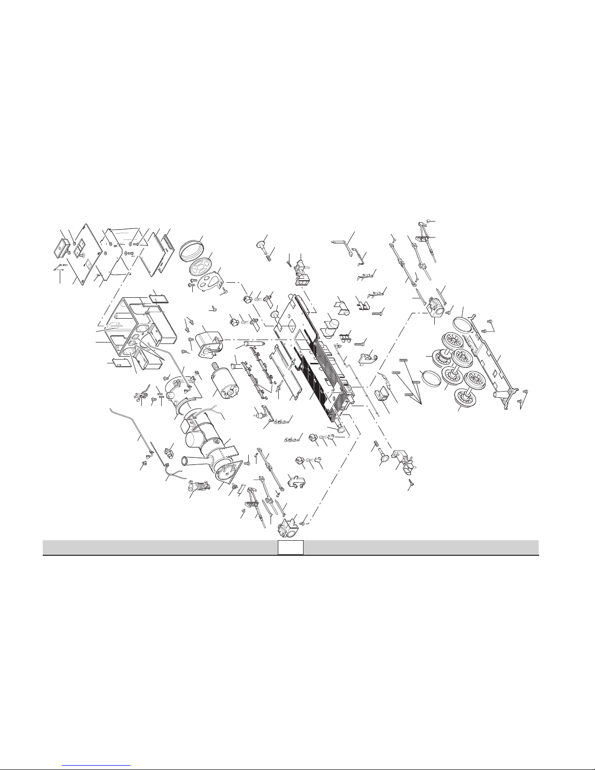
46 Federpakete 109 956
47 Einsatzeil 397 390
48 Kupplung 583 080
49 Linsenschraube 583 110
50 Zylinder links 431 130
51 Gestänge links 397 430
52 Zylinderschraube 785 350
53 Zylinder rechts 431 160
54 Gestänge rechts 397 440
Treibgestell
55 Motor 206 303
56 Getriebe 352 200
57 Zylinderschraube 785 350
58 Zylinderschraube 785 350
59 Traggestell 411 014
mit
60 Luftkessel I 421 400
61 Luftkessel II 421 430
62 Druckluftleitung 421 550
63 Bremszugstange links 421 520
64 Handbremshebel 421 540
65 Bremszugstange rechts 421 530
66 Bremszylinder 421 510
67 Bremsbacke links 421 470
68 Bremsbacke rechts 421 480
69 Trittstufe 421 460
70 Gleitbahnträger links 421 380
71 Gleitbahnträger rechts 421 390
72 Gleitbahn 351 010
73 Treibstange links 397 940
74 Treibstange rechts 397 950
75 Umsteuerwelle 351 030
76 Kuppelstange links 397 300
77 Kuppelstange rechts 352 150
78 Sechskantansatzschraube 784 950
79 Sechskantansatzschraube 755 240
80 Kuppelradsatz vorn 421 590
81 Treibradsatz 421 650
82 Kuppelradsatz hinten 109 652
83 Haftreifen 451 039
84 Druckfeder 366 440
85 Schleifer 421 570
86 Isolierstück 421 560
87 Deckel (Achshalter) 421 720
88 Zylinderschraube 785 350
Page 32

This device complies with Part 15 of the FCC Rules.
Operation is subject to the following two conditions:
(1) This device may not cause harmful interference, and
(2) this device must accept any interference received, including
interference that may cause undesired operation.
Gebr. Märklin & Cie. GmbH
Postfach 8 60
D-73008 Göppingen
www.maerklin.com
Änderungen vorbehalten
© by Gebr. Märklin & Cie GmbH
108745/0306/SmEf
 Loading...