

Page 1
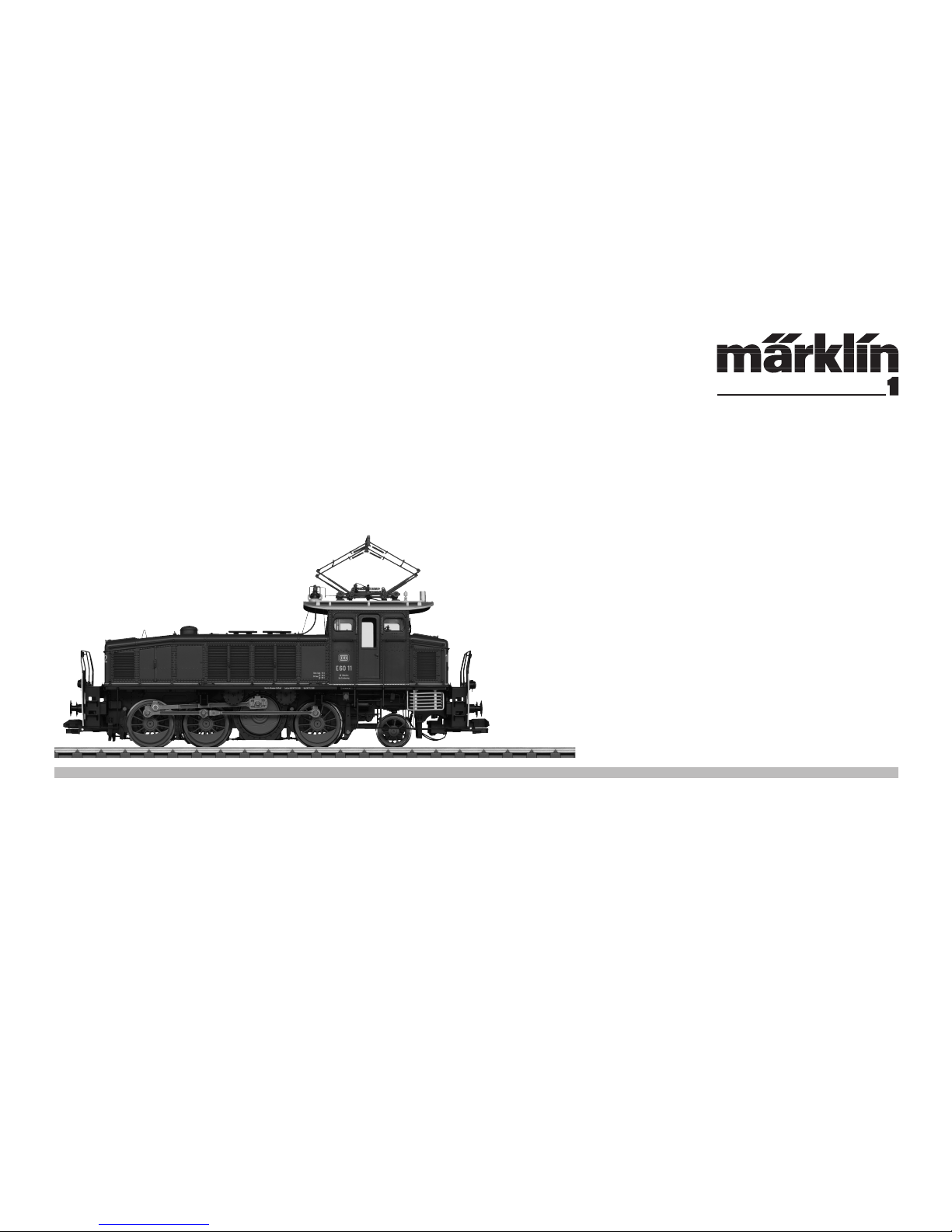
Modell der Elektrolokomotive BR E 60
55605
Page 2

2
Inhaltsverzeichnis: Seite
Informationen zum Vorbild 4
Inbetriebnahme 6
Wartung und Instandhaltung 9
Sicherheitshinweise 10
Wichtige Hinweise 10
Funktionen 10
Schaltbare Funktionen 11
Parameter / Register 12
Betrieb auf der Anlage 34
Table of Contents: Page
Information about the prototype 4
Putting into Operation 6
Service and maintenance 9
Safety Notes 14
Important Notes 14
Functions 14
Controllable Functions 15
Parameter / Register 16
Operation on a layout 34
Sommaire : Page
Informations concernant la
locomotive réelle 5
Mise en service 6
Entretien et maintien 9
Remarques importantes sur la sécurité 18
Information importante 18
Fonctionnement 18
Fonctions commutables 19
Paramètre / Registre 20
Exploitation sur réseau 34
Page 3

3
Indice de contenido: Página
Puesta en servicio 7
El mantenimiento 9
Aviso de seguridad 26
Notas importantes 26
Funciones 26
Funciones posibles 27
Parámetro / Registro 28
Funcionamiento del sistema 34
Inhoudsopgave: Pagina
Informatie van het voorbeeld 5
Ingebruikname 7
Onderhoud en handhaving 9
Veiligheidsvoorschriften 22
Belangrijke aanwijzing 22
Functies 22
Schakelbare functies 23
Parameter / Register 24
Bedrijf op een modelbaan 34
Indice del contenuto: Pagina
Messa in esercizio 7
Manutenzione ed assistere 9
Avvertenze per la sicurezza 30
Avvertenze importanti 30
Funzioni 30
Funzioni commutabili 31
Parametro / Registro 32
Exploitation sur réseau 34
Page 4

4
Vorbild • Prototype Exploitation dans le réelle • Grootbedrijf
Informationen zum Vorbild
„Saubere Loks für den Rangierdienst auf elektrifizierten Bahnhöfen“
hieß die Devise der DRG Mitte der 1920er Jahre in Bayern. Speziell
für die ausgedehnten Gleisanlagen der Münchner Bahnhöfe bestellte
sie 1926 zwei Elektroloks, um diese rauchfreie Betriebsart auch bei
Rangierleistungen nutzen zu können. Aus Gründen einer einheitlichen
Ersatzteilvorhaltung forderte die DRG, möglichst viele Bauteile der gerade beschafften E 52 und E 91 zu übernehmen. Von der E 91 kam der
Winterthur-Schrägstangenantrieb mit Blindwelle und den drei Kuppelradsätzen. Die Antriebsleistung stellte ein Doppelmotor zur Verfügung,
welcher auch bei der E 52 oder E 91 zur Anwendung kam. Ursprünglich
besaßen die Lokomotiven eine Stromabnehmer-Sonderkonstruktion
mit zwei weit auseinanderliegenden Schleifstücken, um Trennstellen in
der Fahrleitung besser überbrücken zu können.
Die ersten beiden Maschinen wurden 1927 als E 60 01 und 02 in Dienst
gestellt. Bis Juni 1934 folgten in mehreren Kleinserien die E 60 03-14,
welche zum Teil auch auf anderen bayerischen Bahnhöfen zum Einsatz
kamen. Neben dem Rangierdienst sah man die E 60 vor Nahgüterzügen
und Übergaben. Ihre charakteristische Gestaltung mit den beiden Vorbauten, der hintere langgestreckt und der vordere relativ kurz, verhalf
ihnen schnell zu dem Beinamen „Bügeleisen“.
Nach dem Anschluss von Österreich gelangten ab 1938 auch einige
Maschinen ins „Anschlussgebiet“ nach Innsbruck, Kufstein und Wörgl. Alle E 60 überstanden den Krieg ohne allzu schwere Schäden und
die in Österreich verbliebenen kehrten im Rahmen eines Loktausches
1945/46 nach Bayern zurück. 1957/58 ließ die DB die Loks gründlich
aufarbeiten und modernisieren. So erhielten sie u.a. Rangierbühnen
über den Puffern, zusätzliche Fenster und eine neue Verkabelung. Bis
1964 fuhren die E 60 (ab 1968: 160) nur wieder in Bayern, dann kam
Heidelberg als neuer Standort hinzu. Erste Ausmusterungen erfolgten
1977 und mit der Abstellung der 160 012 im Juni 1983 war gleichzeitig
der Rangierdienst mit Elektroloks bei der DB beendet. Als Museumslokomotiven blieben die 160 009, 010 und 012 erhalten.
Information about the prototype
„Clean locomotives for switching work at electrified stations“ was the
DRG‘s slogan in the Mid-Twenties in Bavaria. It ordered two electric
locomotives in 1926 especially for the extended track layouts of the
Munich stations in order to be able to use this smoke-free method
of operation in switching work too. The DRG stipulated the use of as
many components of the newly purchased E 52 and E 91 as possible
in the interests of standardized spare parts inventory. The Winterthur
diagonal rod drive with a jackshaft and three coupled wheel sets came
from the E 91. The drive performance was provided by a double motor
that was also used on the E 52 or E 91. Originally, the locomotives had
a special design pantograph with two widely spaced contact strips to
better bridge separation points in the catenary.
The first two units were placed into service in 1927 as E 60 01 and
02. Several small run series followed by June of 1934, the E 60 03-14,
which were also used in part at other Bavarian stations. In addition to
switching work, the E 60 was also planned for local freight trains and
transfer work. Its characteristic design with the two hoods, the rear
one being long and the front one relatively short, quickly generated its
nickname „Flat Iron“.
After the annexation of Austria, several units went starting in 1938 to
the „Annexation Area“ to Innsbruck, Kufstein, and Wörgl. All of the E
60 locomotives survived the war without extensive damage and the
units still in Austria came back to Bavarian as part of a locomotive
swap in 1945/46. In 1957/58, the DB had the locomotives fundamentally
overhauled and updated. They thus were equipped with switching
platforms above the buffers, additional windows, and new wiring.
By 1964 the E 60 units (from 1968 on: 160) were only running again in
Bavaria. Then came Heidelberg as a new home base. The first units to
be retired were in 1977 and with the storage of road number 160 012
in June of 1983 switching service with electric locomotives on the DB
also ended. Road numbers 160 009, 010, and 012 remain preserved as
museum locomotives.
Page 5

5
Vorbild • Prototype Exploitation dans le réelle • Grootbedrijf
Informations concernant la locomotive réelle
«Des locomotives propres pour le service de manœuvre dans des gares
électrifiées», telle était la devise de la DRG au milieu des années 1920 en
Bavière. C’est spécialement pour les réseaux de voies très étendus des
gares munichoises qu’elle commanda, en 1926, deux locomotives électriques
afin de pouvoir exploiter ce mode de traction « non fumeur » également pour
le service de manœuvre. Pour disposer d’un stock de pièces de rechange
homogène, la DRG exigea de reprendre un maximum de pièces des E 52 et E
91 qu’elle venait d’acheter. Le système de transmission par bielles obliques
Winterthur avec arbre secondaire de renvoi et les trois essieux couplés
provenait de la E 91. La puissance de transmission était assurée par un
moteur double, également utilisé sur la E 52 ou la E 91. A l’origine, les locomotives présentaient une construction spéciale de pantographes avec deux
semelles d’archet très espacées afin de pouvoir pallier des coupures dans
l’alimentation du fil de contact.
Les deux premières machines, E 60 01 et 02, furent mises en service en 1927.
Jusqu’en juin 1934 suivirent en plusieurs petites séries les E 60 03 à 14 qui
furent en partie aussi utilisées dans d’autres gares bavaroises. En dehors du
service de manœuvre, les E 60 servaient également à remorquer des trains
marchandises locaux et à la mise à disposition de rames. Leur allure caractéristique avec les deux capots, assez long à l’arrière et relativement court à
l’avant, leur valut rapidement le surnom de «fer à repasser».
A partir de 1938, après l’annexion de l’Autriche, certaines machines se
retrouvèrent en «zone annexée», à Innsbruck, Kufstein et Wörgl. Toutes les
E 60 survécurent à la guerre sans trop de dégâts et les machines restées en
Autriche furent rapatriées en Bavière en 1945/46 à l‘occasion d’un échange
de locos. En 1957/58, la DB fit remettre en état et moderniser des locos de
fond en comble. Elles furent ainsi équipées de plates-formes de manœuvre
au-dessus des tampons, de fenêtres supplémentaires et d’un nouveau
câblage. Jusqu’en 1964, les E 60 (160 à partir de 1968) ne circulèrent à nouveau qu’en Bavière, puis furent affectées aussi à Heidelberg. Les premières
réformes eurent lieu en 1977 et la réforme de la 160 012 en juin 1983 marqua
pour la DB la fin du service de manœuvre avec locomotives électriques. Les
160 009, 010 et 012 furent conservées comme locomotives musée.
Informatie van het voorbeeld
„Schone locs voor de rangeerdienst op geëlektrificeerde stations“ was
het devies van de DRG halverwege de jaren 20 in Beieren. Speciaal voor
de uitgebreide sporen van de stations in Múnchen weren in 1026 twee
elektrische locs besteld om deze rookloze vorm ook bij het rangeren te
kunnen gebruiken. Om redenen van een zo economisch mogelijk gebruik
van vervangende onderdelen eiste de DRG om zoveel mogelijk onderdelen van de onlangs aangeschafte E 52 en E 91 over te nemen. Van de
E 91 is de Winterthur-aandrijving met schuine stangen en blinde as en
de drie sets gekoppelde wielen afkomstig. Het aangedreven vermogen
werd beschikbaar geteld door een dubbele motor die ook bij de E 52 en E
91 werd toegepast. Oorspronkelijk hadden de locomotieven een bijzondere stroomafnemer met twee ver uit elkaar liggende sleepstukken, om
onderbrekingen in de bovenleiding beter te kunnen overbruggen.
De eerste twee machines werden in 1927 als E 60 01 en 02 in dienst
genomen. Tot juni 1934 volgden in verschillende kleine series de E 60
03-14, die voor een deel ook op andere Beierse stations werden ingezet.
Naast de rangeerdienst werd de E 60 ook gebruikt voor regionale goederentreinen en overdrachten. De kenmerkende vormgeving met de beide
voorbouwen, de achterste langgestrekt en de voorste relatief kort, gaf
hen al snel de bijnaam „Strijkijzer“.
Na de aansluiting met Oostenrijk belandden vanaf 1938 ook enige
machines in het „Anschlussgebiet“ in Innsbruck, Kufstein en Wörgl. Alle
E 60‘s overleefden de oorlog zonder zware schade en de in Oostenrijk
achtergebleven machines keerden in 1945/46 terug in Beieren in het
kader van een locruil. In 1957/58 liet de DB de locs grondig reviseren en
moderniseren. Zo kregen ze ondermeer rangeerbordessen boven de
buffers, extra ramen en nieuwe bedrading. Tot 1964 reed de E 60 (Vanaf
1968: 160) weer alleen in Beieren, waarna Heidelberg als nieuwe locatie
werd toegevoegd. De eerste buitendienststellingen vonden plaats in
1977 en met de buitendienststelling van de 160 012 in juni 1983 kwam tevens een einde aan de rangeerdienst met elektrische locs bij de DB. Als
museumslocomotieven zijn de 160 009, 010 en 012 behouden gebleven.
Page 6

6
Betrieb • Operation • Fonctionnement Exploitatie • Operación • Operazione
Vor dem ersten Betrieb
Dieses Modell ist hinsichtlich der Technik
und er Ausführung besonders aufwändig und
hochwertig. Die meisten angesteckten oder
verbauten Teile sind aus Metall gefertigt.
Solche Teile können nicht so einfach getauscht werden, wie z.B. Kunststoffteile. Bitte
beachten Sie daher, dass Sie dieses Modell
besonders vorsichtig handhaben sollten.
Für den Tausch von Teilen oder Reparaturen
wenden Sie sich bitte an den Märklin Service.
Hinweise
• Das Modell muss vor dem ersten Betrieb
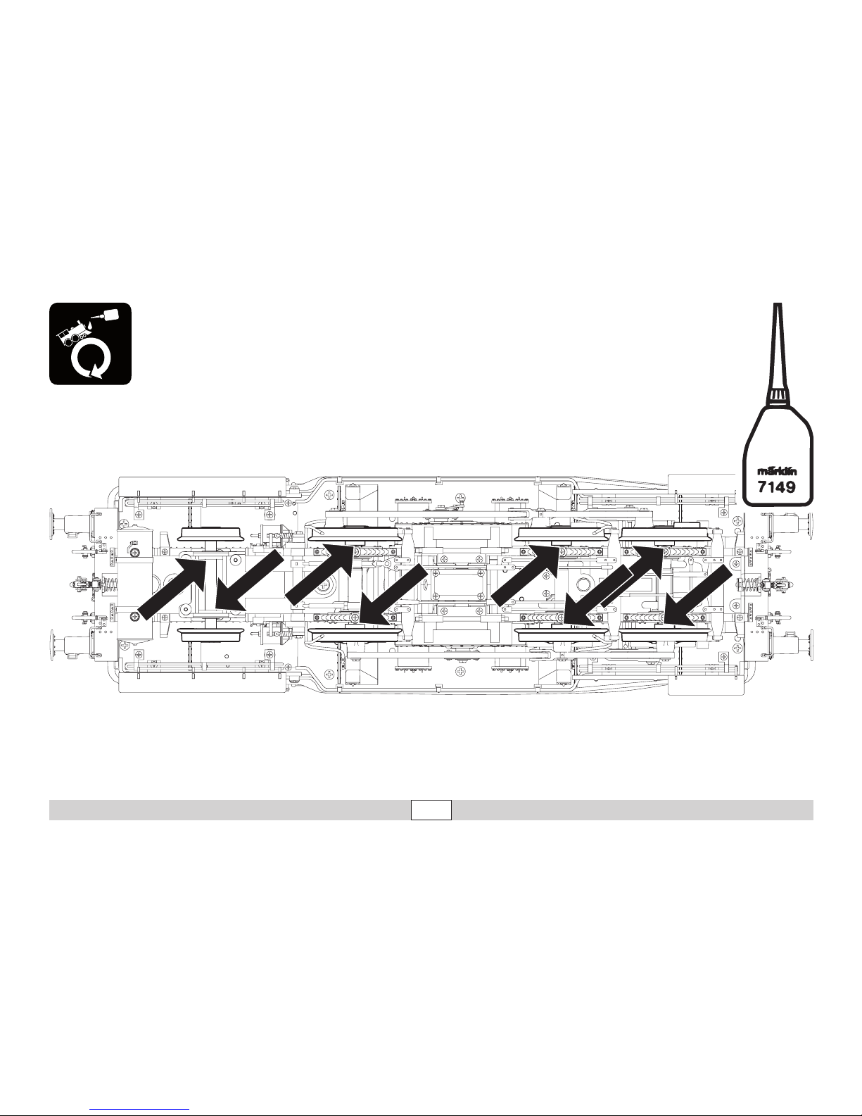
geschmiert werden (siehe Seite 38).
• Der Dachstromabnehmer wird über einen
Servo-Motor angetrieben. Er darf niemals
von Hand ausgefahren werden, kann aber
z.B. zum Verpacken des Modells von Hand
eingefahren werden.
• Im Analogbetrieb ist der Strohmabnehmer
eingefahren.
• Der Stromabnehmer kann eingerastet werden. Wir empfehlen den Stromabnehmer
vor dem Ausrasten auszufahren.
Before Operating for the First Time
This model is especially complex and costly
in terms of its technology. Most of the applied
parts are constructed of metal. Such parts
cannot be replaced so easily as for example
plastic parts. Please therefore note that you
should handle this model with special care.
Please contact Märklin Service for replacement of parts or for repairs.
Notes
• This model must be lubricated before operating it for the first time (see page 38).
• The pantograph is powered by a servomotor. It must never be raised by hand. It
can be lowered by hand for things such as
packing the model.
• The pantograph is lowered in analog operation.
• The pantograph can be locked into place.
We recommend raising the pantograph
before unlocking it.
Avant la première mise en service
Ce modèle bénéficie d’une technicité de
haut niveau et d‘une finition particulièrement
soignée. La plupart des éléments rapportés
ou intégrés sont en métal. De tels éléments ne
se remplacent pas aussi facilement que des
éléments en plastique par exemple. Veillez
donc à manipuler ce modèle avec un soin
particulier.
Pour les pièces détaillées ou d’éventuelles
réparations, veuillez vous adresser au Service
Märklin.
Remarques
• Le modèle doit être graissé avant sa première mise en service (voir page 38)
• Le pantographe est entraîné par un servo-
moteur. S’il ne doit en aucun cas être
levé manuellement, il peut par contre être
baissé manuellement, par exemple pour
emballer le modèle.
• En mode d’exploitation analogique, le pantographe est abaissé.
• Le pantographe peut être verrouillé. Nous
conseillons de lever le pantographe avant
le déverrouillage.
Page 7

7
Betrieb • Operation • Fonctionnement Exploitatie • Operación • Operazione
Voor het eerste gebruik
Dit model is vanwege de techniek en de
uitvoering bijzonder uitgewerkt en hoogwaardig uitgevoerd. De meeste opgestoken of
aangebouwde delen zijn van metaal gemaakt.
Dergelijke delen kunnen niet zo eenvoudig
vervangen worden dan kunststof delen. Let
er daarom op dat u het model uitermate voorzichtig behandelt.
Voor het vervangen van delen of reparaties
kunt u zich wenden tot het Märklin service
centrum.
Aanwijzingen
• Het model moet voor het eerste gebruik
gesmeerd worden (zie afb. 38)
• De pantograaf wordt aangedreven door
een servo-motor. Hij mag nooit handmatig
omhoog gehaald worden maar kan voor het
verpakken van het model wel handmatig
neergelaten worden.
• In het analoge bedrijf is de pantograaf
neergelaten.
• De pantograaf kan vastgeklikt worden.
Het is aan te bevelen de pantograaf eerst
omhoog te laten en dan handmatig naar
beneden te duwen en vast te klikken.
• De pantograaf wordt aangedreven door
een servo-motor. Hij mag nooit handmatig
omhoog gehaald worden maar kan voor het
verpakken van het model wel handmatig
neergelaten worden.
Antes de la primera puesta en servicio
En los aspectos de tecnología incorporada y
ejecución, este modelo en miniatura es muy
sofisticado y avanzado. La mayoría de piezas
enchufadas o incorporadas son de metal.
Tales piezas no se pueden sustituir con la
facilidad de, p. ej., las piezas de plástico. Por
este motivo, tenga presente que debe manejar este modelo con suma precaución.
Para la sustitución de piezas o para reparaciones, diríjase al Servicio de Märklin.
Consejos
• Lubricar el modelo en miniatura antes de la
primera puesta en servicio (véase 38).
• El pantógrafo es accionado por un servomotor. Nunca está permitido desplegarlo
manualmente, pero, por ejemplo, se puede
replegar manualmente para embalar el
modelo.
• El pantógrafo está replegado en funcionamiento en modo analógico.
• Es posible engatillar el pantógrafo. Recomendamos desplegar el pantógrafo antes
de desengatillarlo.
Prima del primo funzionamento
Questo modello è particolarmente complicato
e di alto pregio sotto l’aspetto della tecnologia e dell’esecuzione. La maggior parte degli
elementi applicati a innesto o riportati sono
realizzati di metallo. Tali componenti non possono venire sostituiti tanto facilmente, come
ad es. le parti di materiale sintetico. Vogliate
pertanto prestare attenzione, affinché Voi
maneggiate questo modello con particolare
cautela.
Per la sostituzione di componenti oppure
riparazioni, vogliate rivolgerVi al Servizio
Assistenza Märklin.
Avvertenza
• Tale modello deve venire lubricato prima
del primo funzionamento
(si veda pagina 38).
• Il pantografo sul tetto viene azionato mediante un servo-motore. Esso non deve mai
venire sollevato a mano, tuttavia può venire
abbassato a mano ad es. per l’imballaggio
del modello.
• Nel funzionamento analogico il pantografo
è abbassato.
• Il pantografo può venire bloccato. Noi consigliamo prima dello sblocco di fare alzare il
pantografo.
Page 8
8
Betrieb • Operation • Fonctionnement Exploitatie • Operación • Operazione
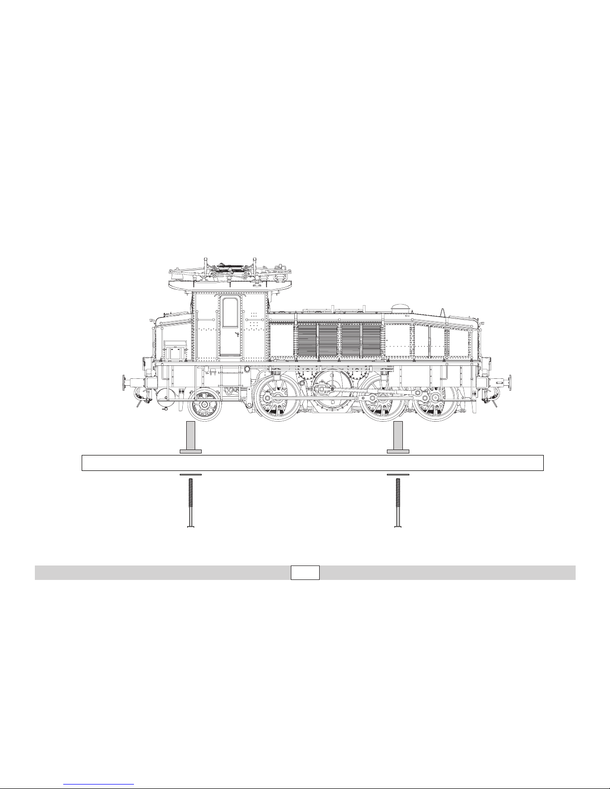
Für den sicheren Transport wurde dieses
schwere Modell auf dem Sockel angeschraubt. Bitte transportieren Sie dieses
Modell nur trocken und so gesichert und in
der Originalkassette.
This heavy model was bolted to the
base for safe transport. Please transport this model only when it is dry and
secured as described in preceding
sentence and in the original box.
Afin d’éviter tout problème lié au transport, ce
modèle lourd a été vissé sur son socle. Veillez
à le transporter uniquement sous cette condi-
tion, au sec et dans son boîtier d’origine.
Voor een veilig transport is het model op een
sokkel vast geschroefd. Transporteer het
model a.u.b. alleen droog en vastgeschroefd
in de originele cassette.
Para hacer posible un transporte seguro, se
ha atornillado este pesado modelo al zócalo.
Transporte este modelo en miniatura siempre
seco y bien asegurado y en su casete original.
Per un trasporto sicuro questo pesante modello è stato fissato con viti al basamento. Si
prega di trasportare questo modello soltanto
asciutto e così assicurato, e nella cassetta
originale.
Page 9
9
Betrieb • Operation • Fonctionnement Exploitatie • Operación • Operazione
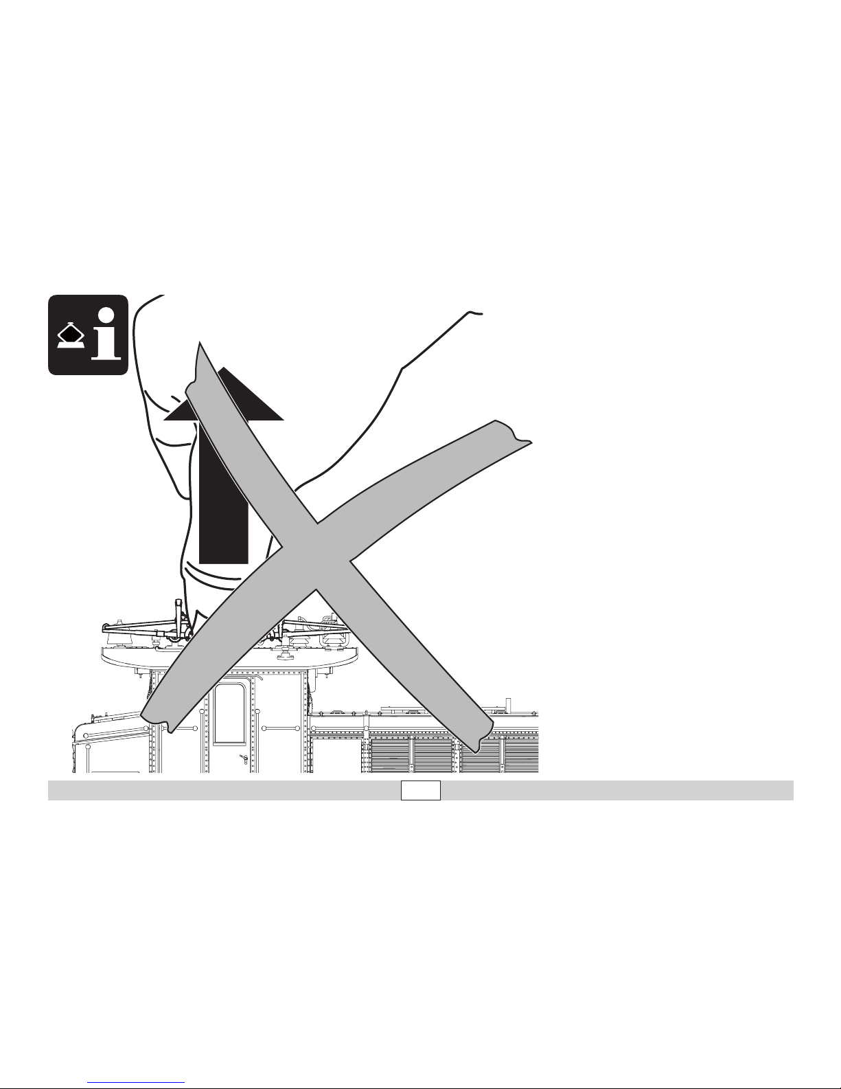
• Der Dachstromabnehmer wird über einen
Servo-Motoren angetrieben. Er darf niemals von Hand ausgefahren werden, kann
aber z.B. zum Verpacken des Modells von
Hand eingefahren werden.
• The pantograph is powered by a servomotor. It must never be raised by hand. It
can be lowered by hand for things such as
packing the model.
• Le pantographe est entraîné par un servo-
moteur. S’il ne doit en aucun cas être
levé manuellement, il peut par contre être
baissé manuellement, par exemple pour
emballer le modèle.
• De pantograaf wordt aangedreven door
een servo-motor. Hij mag nooit handmatig
omhoog gehaald worden maar kan voor het
verpakken van het model wel handmatig
neergelaten worden.
• El pantógrafo es accionado por un servomotor. Nunca está permitido desplegarlo
manualmente, pero, por ejemplo, se puede
replegar manualmente para embalar el
modelo.
• Il pantografo sul tetto viene azionato mediante un servo-motore. Esso non deve mai
venire sollevato a mano, tuttavia può venire
abbassato a mano ad es. per l’imballaggio
del modello.
Page 10

10
Betrieb • Operation • Fonctionnement Exploitatie • Operación • Operazione
Sicherheitshinweise
• Die Lok darf nur mit einem dafür bestimmten Betriebssystem
(Gleichstrom [DC] = max 18V±, Märklin Wechselstrom,
Märklin Digital oder Märklin Systems) eingesetzt werden.
• Nur Schaltnetzteile/Transformatoren verwenden, die Ihrer örtlichen
Netzspannung entsprechen.
• Die Lok darf nur aus einer Leistungsquelle versorgt werden.
• Beachten Sie unbedingt die Sicherheitshinweise in der Bedienungs-
anleitung zu Ihrem Betriebssystem.
• Für den konventionellen Betrieb der Lok muss das Anschlussgleis
entstört werden. Dazu ist das Entstörset 104770 zu verwenden. Für
Digitalbetrieb ist das Entstörset nicht geeignet.
• Das verwendete Gleisanschlusskabel darf maximal 2 Meter lang sein.
• Setzen Sie das Modell keiner direkten Sonneneinstrahlung, starken
Temperaturschwankungen oder hoher Luftfeuchtigkeit aus.
• ACHTUNG! Funktionsbedingte scharfe Kanten und Spitzen.
Wichtige Hinweise
• Wegen der hohen Leistungsaufnahme dieser Lokomotive ist der Betrieb mit der Mobile Station 60652/60653 nur eingeschränkt möglich.
• Die Bedienungsanleitung ist Bestandteil des Produktes und muss
deshalb aufbewahrt sowie bei Weitergabe des Produktes mitgegeben werden.
• Wartung, Instandhaltung und Reparaturen dürfen nur durch Erwachsene durchgeführt werden.
• Für Reparaturen oder Ersatzteile wenden Sie sich bitte an Ihren
Märklin-Fachhändler.
•
Gewährleistung und Garantie gemäß der beiliegenden Garantieurkunde.
• Entsorgung: www.maerklin.com/en/imprint.html
Funktionen
•
Die Betriebsart (AC/DC, Mfx, Märklin-Motorola oder DCC) wird
automatisch erkannt.
• Mfx-Technologie für Mobile Station / Central Station.
Name ab Werk: E 60 13
• Adresse ab Werk: (Märklin) 64/65 / (DCC) 3
• Veränderbare Anfahrverzögerung (ABV).
• Veränderbare Bremsverzögerung (ABV).
• Veränderbare Höchstgeschwindigkeit.
• Einstellen der Lokparameter (Adresse, Anfahr-/Bremsverzögerung,
Höchstgeschwindigkeit usw.): mit Control Unit und DCC (CV Programmierung), Mobile Station oder Central Station.
• Fahrtrichtungsabhängige Stirnbeleuchtung.
• Das Modell ist für den Betrieb auf Märklin 1-Gleisen entwickelt. Ein
Betrieb auf anderen Gleissystemen geschieht auf eigenes Risiko.
• Befahrbarer Mindestradius: 1020 mm
• Im Analogbetrieb stehen nur die Fahr- und Lichtwechselfunktionen
zur Verfügung.
Page 11
11
Betrieb • Operation • Fonctionnement Exploitatie • Operación • Operazione
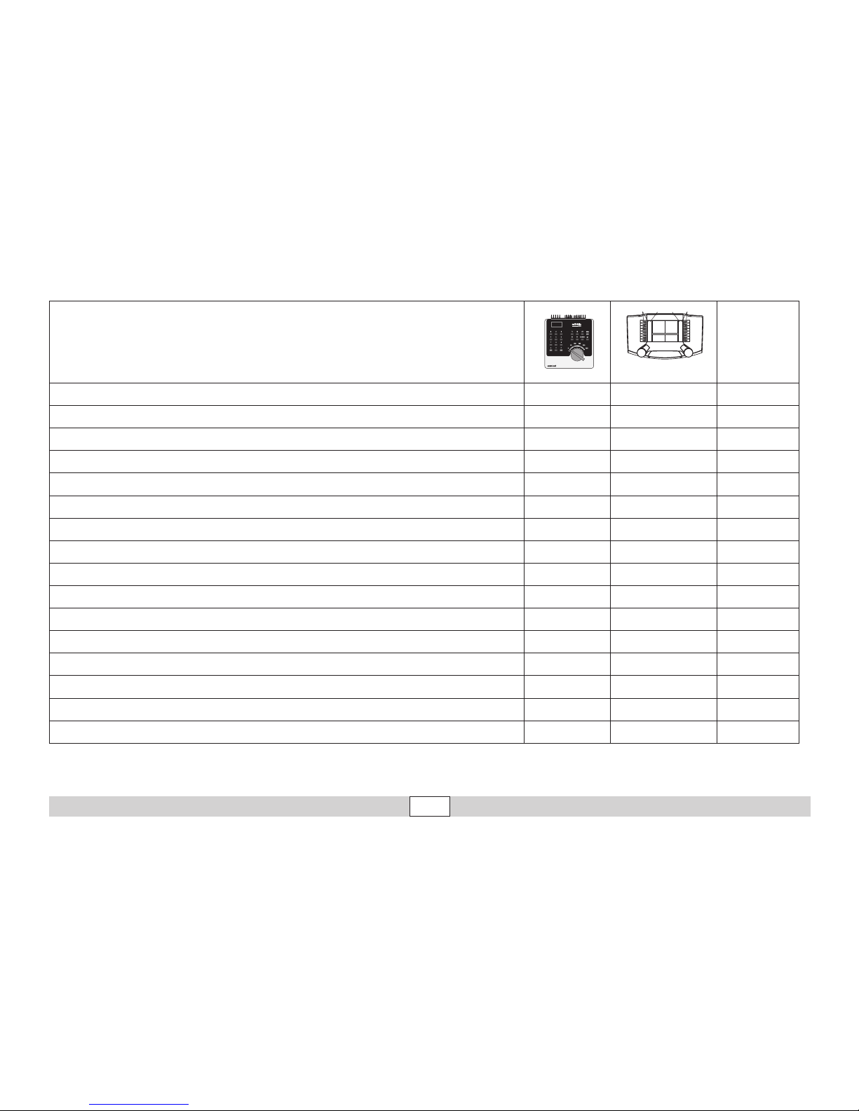
Schaltbare Funktionen
Digital/Systems
Spitzensignal function/off Funktion f0
Pantograph heben/senken f1 (62) Funktion f1 AUX 5, Sound 4
Betriebsgeräusch f2 (62) Funktion f2
Geräusch: Pfeife f3 (62) Funktion f3 Sound 1
Führerstandsbeleuchtung f4 (62) Funktion f4 AUX 2
Telex-Kupplung vorne, mit Geräusch f1 (63) Funktion f5
AUX 3, Sound 12
Spitzenlicht vorne f2 (63) Funktion f6
Telex-Kupplung hinten, mit Geräusch f3 (63) Funktion f7
AUX 4, Sound 13
Spitzenlich hinten f4 (63) Funktion f8
Geräusch: Bremsenquietschen aus — Funktion f9
ABV, aus — Funktion f10
Geräusch: Glocke — Funktion f11 Sound 3
Signalleuchte — Funktion f12 AUX 1
Geräusch: Druckluft ablassen — Funktion f13 Sound 15
Geräusch: Rangieransage — Funktion f14 Sound 6
Geräusch: Rangierpfiff — Funktion f15 Sound 2
f0 f8 f0f8
Page 12

12
Betrieb • Operation • Fonctionnement Exploitatie • Operación • Operazione
CV Bedeutung Wert für 6021 Wert DCC
01 Adresse 01 – 80 (62)
1 – 127 (3)
CV 29/Bit 5 =0
02 PoM Minimalgeschwindigkeit — 0 – 255 (20)
03 PoM Anfahrverzögerung 01 – 63 0 – 255 (15)
04 PoM Bremsverzögerung 01 – 63 0 – 255 (15)
05 PoM Maximalgeschwindigkeit 01 – 63 0 – 255 (245)
08 Werkreset/Herstellerkennung 08 08 (131)
13 PoM Funktionen F1 - F8 im Analogbetrieb — 0 – 255 (0)
14 PoM Funktionen F9 - F15 und Licht im Analogbetrieb — 0 – 255 (1)
17 Erweiterte Adresse (oberer Teil CV29 Bit 5 =1) — 192 – 255 (192)
18 Erweiterte Adresse (unterer Teil CV29 Bit 5 =1) — 0 – 255 (128)
19 Traktionsadresse — 0 – 255 (0)
21 PoM Funktionen F1 - F8 bei Traktion — 0 – 255 (0)
22 PoM Funktionen F9 - F15 und Licht bei Traktion — 0 – 255 (0)
27 PoM
Bit 0 = Bremsstrecke ein/aus
Bit 4 = normales Bremsverhalten
Bit 5 = inverses Bremsverhalten
—
0, 1, 16, 17, 32,
33, 48, 49
29
Bit 0: Umpolung Fahrtrichtung
Bit 1: Anzahl Fahrstufen 14 oder 28/128
Bit 2: DCC Betrieb mit Bremsstrecke
Bit 5: Adressumfang 7 Bit / 14 Bit
—
0 / 1 (0)*
0 / 2 (2)*
0 / 4 (4)*
0 / 32 (0)*
50 PoM alternative Formate — 0 – 255 (15)
60 PoM
Multibahnhofsansage
Bit 0 – 3 = Anzahl der Bahnhöfe
Bit 4 = letzter Bahnhof kehrt Reihenfolge um
Bit 5 = Lokrichtung bestimmt Reihenfolge
Bit 6 = Reihenfolge Grundeinstellung
— 0 – 127 (1)
Page 13

13
Betrieb • Operation • Fonctionnement Exploitatie • Operación • Operazione
( ) Werte = Werkseinstellung
DCC: programmieren auf dem Programmiergleis mittels CV Programmierung,
programmieren mit PoM (Program on the Main); dies muss vom Steuergerät unterstützt werden.
* Die Werte der gewünschten Einstellungen sind zu addieren!
Z.B. Anzahl der Fahrstufen 28/128 = 2 + DCC Betrieb mit Bremsstrecke = 4, ergibt Wert = 6
CV Bedeutung Wert für 6021 Wert DCC
63 PoM Lautstärke 01 – 63 (63) 0 – 255 (255)
64 PoM Bremsschwelle 0 – 255 (55)
75 Adresse 2 (1. Folgeadresse) 01 – 80 (63) —
138 PoM Lautstärke Sound „Bremsenquietschen“ — 0 – 255 (200)
139 PoM Lautstärke Sound „Betriebsgeräusch“ — 0 – 255 (255)
140 PoM Lautstärke Sound 1 (Pfeife) — 0 – 255 (200)
141 PoM Lautstärke Sound 2 (Rangierpfiff) — 0 – 255 (200)
142 PoM Lautstärke Sound 3 (Glocke) — 0 – 255 (200)
145 PoM Lautstärke Sound 6 (Rangieransage) — 0 – 255 (200)
151 PoM Lautstärke Sound 12 (Kupplung) — 0 – 255 (128)
152 PoM Lautstärke Sound 13 (Kupplung) — 0 – 255 (128)
153 PoM Lautstärke Sound 14 (Pantograph) — 0 – 255 (255)
154 PoM Lautstärke Sound 15 (Druckluft ablassenr) — 0 – 255 (200)
Page 14

14
Betrieb • Operation • Fonctionnement Exploitatie • Operación • Operazione
Functions
• The mode of operation (AC/DC, Mfx, Märklin Motorola, or DCC) is
recognized automatically.
• Mfx technology for the Mobile Station / Central Station.
Name set at the factory: E 60 13
• Address set at the factory: (Märklin) 64/65 / (DCC) 3
• Adjustable Acceleration delay (ABV).
• Adjustable Braking delay (ABV).
• Adjustable maximum speed.
• Setting locomotive parameters (address, acceleration/braking delay,
maximum speed, etc.): with the Control Unit and DCC (CV programming), Mobile Station, or the Central Station.
• Headlights, changing over with the direction of travel.
• The model is designed for operation on Märklin 1 Gauge track. As
the consumer you assume the risk for operating on other makes of
track.
• Minimum radius for operation: 1020 mm / 40-1/6“.
• Only the train control functions and headlight changeover feature
are available in analog operation.
Safety Notes
• This locomotive is to be used only with an operating system designed for it (DC power = 18V±, Märklin AC, Märklin Digital,
Märklin Systems).
• Use only switched mode power supply units and transformers that
are designed for your local power system.
• This locomotive must never be supplied with power from more than
one transformer.
• Pay close attention to the safety notes in the instructions for your
operating system.
• The feeder track must be equipped to prevent interference with
radio and television reception, when the locomotive is to be run in
conventional operation. The 104770 interference suppression set is
to be used for this purpose.
• The wire used for feeder connections to the track may only be a
maximum of 2 meters / 78 inches long.
• Do not expose the model to direct sunlight, extreme changes in
temperature, or high humidity.
• WARNING! Sharp edges and points required for operation.
Important Notes
• Due to the high power requirements for this heavy locomotive, there
are only limited possibilities for operation with the
60652/60653
Mobile Station.
• The operating instructions are a component part of the product and must
therefore be kept as well as transferred along with the product to others.
• Maintenance, servicing, and repairs may only be done by adults.
• Please see your authorized Märklin dealer for repairs or spare parts.
• The warranty card included with this product species the warranty
conditions.
• Disposing: www.maerklin.com/en/imprint.html
Page 15
15
Betrieb • Operation • Fonctionnement Exploitatie • Operación • Operazione
Controllable Functions
Digital/Systems
Headlights function/off Function f0
Pantograph raise/lower f1 (62) Function f1 AUX 5, Sound 4
Operating sounds f2 (62) Function f2
Sound effect: whistle blast f3 (62) Function f3 Sound 1
Engineer‘s cab lighting f4 (62) Function f4 AUX 2
Telex coupler in the front, with sound f1 (63) Function f5
AUX 3, Sound 12
Front headlights f2 (63) Function f6
Rear Telex coupler, with sound f3 (63) Function f7
AUX 4, Sound 13
Rear headlights f4 (63) Function f8
Sound effect: Squealing brakes off — Function f9
ABV; OFF — Function f10
Sound effect: Bell — Function f11 Sound 3
Signal light — Function f12 AUX 1
Sound effect: Letting off air — Function f13 Sound 15
Sound: brakeman‘s announcement — Function f14 Sound 6
Sound e Sound effect: Switching whistle ffect: sanding — Function f15 Sound 2
f0 f8 f0f8
Page 16

16
Betrieb • Operation • Fonctionnement Exploitatie • Operación • Operazione
CV Discription 6021 Value DCC Value
01 Address 01 – 80 (62)
1 – 127 (3)
CV 29/Bit 5 =0
02 PoM Minimum Speed — 0 – 255 (20)
03 PoM Acceleration delay 01 – 63 0 – 255 (15)
04 PoM Braking delay 01 – 63 0 – 255 (15)
05 PoM Maximum speed 01 – 63 0 – 255 (245)
08 Factory Reset / Manufacturer Recognition 08 08 (131)
13 PoM Functions F1 - F8 in analog operation — 0 – 255 (0)
14 PoM Functions F9 - F15 and lights in analog operation — 0 – 255 (1)
17 Extended address (upper part CV29 Bit 5 = 1) — 192 – 255 (192)
18 Extended address (lower part CV29 Bit 5 = 1) — 0 – 255 (128)
19 Multiple Unit Address — 0 – 255 (0)
21 PoM Functions F1 - F8 on Multiple Unit — 0 – 255 (0)
22 PoM Functions F9 - F15 and lights on Multiple Unit — 0 – 255 (0)
27 PoM
Bit 0 = Braking area on/off
Bit 4 = Normal braking behavior
Bit 5 = Inverse braking behavior
—
0, 1, 16, 17, 32,
33, 48, 49
29
Bit 0: Reversing direction
Bit 1: Number of speed levels 14 or 28/128
Bit 2: DCC operation with braking area
Bit 5: Address length 7 Bit / 14 Bit
—
0 / 1 (0)*
0 / 2 (2)*
0 / 4 (4)*
0 / 32 (0)*
50 PoM Alternative Formats — 0 – 255 (15)
60 PoM
Multiple station announcements
Bit 0 – 3 = Number of stations
Bit 4 = Last station reverses the sequence.
Bit 5 = Locomotive direction determines the sequence.
Bit 6 = Basic setting for sequence.
— 0 – 127 (1)
Page 17

17
Betrieb • Operation • Fonctionnement Exploitatie • Operación • Operazione
( ) Values = factory settings
DCC: programming on the programming track by means of CV programming,
programming with PoM (Program on the Main); this must be supported by the controller you are using.
* The values for the desired setting must be added!
Example: The number of speed levels 28/128 = 2 + DCC operation with a braking route = 4, results in the value = 6
CV Discription 6021 Value DCC Value
63 PoM Volume 01 – 63 (63) 0 – 255 (255)
64 PoM Brake threshold — 0 – 255 (55)
75 Address 2 (1st consecutive address) 01 – 80 (63) —
138 PoM Volume for sound "squealing brakes" — 0 – 255 (200)
139 PoM Volume for sound "operating sounds" — 0 – 255 (255)
140 PoM Volume for sound 1 (whistle) — 0 – 255 (200)
141 PoM Volume for sound 2 (Switching whistle) — 0 – 255 (200)
142 PoM Volume for sound 3 (Bell) — 0 – 255 (200)
145 PoM Volume for sound 6 (brakeman‘s announcement) — 0 – 255 (200)
151 PoM Volume for sound 12 (Couplers) — 0 – 255 (128)
152 PoM Volume for sound 13 (Couplers) — 0 – 255 (128)
153 PoM Volume for sound 14 (Pantograph) — 0 – 255 (255)
154 PoM Volume for sound 15 (Letting off air) — 0 – 255 (200)
Page 18

18
Betrieb • Operation • Fonctionnement Exploitatie • Operación • Operazione
Remarques importantes sur la sécurité
• La locomotive ne peut être mise en service qu’avec un système
d’exploitation adéquat (DC = 18V ±, Märklin AC, Märklin Digital ou
Märklin Systems).
• Utiliser uniquement des convertisseurs et transformateurs correspondant à la tension du secteur local.
• La locomotive ne peut être alimentée en courant que par une seule
source de courant.
• Veuillez impérativement respecter les remarques sur la sécurité
décrites dans le mode d’emploi de votre système d’exploitation.
• Pour l’exploitation de la locomotive en mode conventionnel, la voie
de raccordement doit être déparasitée. A cet effet, utiliser le set de
déparasitage réf. 104770. Le set de déparasitage ne convient pas
pour l’exploitation en mode numérique.
• Le câble de raccordement à la voie utilisé ne doit en aucun cas
dépasser deux mètres.
• Ne pas exposer le modèle à un ensoleillement direct, à de fortes
variations de température ou à un taux d‘humidité important.
• ATTENTION! Pointes et bords coupants lors du fonctionnement du
produit.
Information importante
• Du fait de l’importance de la puissance absorbée de cette locomotive,
l’exploitation avec la Mobile Station
60652/60653
n’est possible que dans
certaines limites.
• La notice d‘utilisation font partie intégrante du produit ; ils doivent donc
être conservés et, le cas échéant, transmis avec le produit.
• Seules des personnes adultes sont habilitées pour l’entretien, la maintenance et les réparations.
• Pour toute réparation ou remplacement de pièces, adresses-vous à
votre détaillant-spécialiste Märklin.
• Garantie légale et garantie contractuelle conformément au certicat
de garantie ci-joint.
• Elimination : www.maerklin.com/en/imprint.html
Fonctionnement
• Le mode d’exploitation (AC/DC, Mfx, Märklin-Motorola ou DCC) est
identifié automatiquement.
• Technologie mfx pour Mobile Station / Central Station.
Nom encodée en usine : E 60 13
• Adresse départ usine : (Märklin) 64/65 / (DCC) 3
• Temporisation d’accélération réglable (ABV).
• Temporisation de freinage réglable (ABV).
• Vitesse maximale réglable.
• Paramétrer les paramètres des locomotives (adresse, retardement
au démarrage / au freinage, vitesse maximale etc.) avec Control Unit
et DCC (programmation CV), Mobile Station ou Central Station.
• Feux de signalisation avec inversion selon sens de marche.
• Le modèle réduit est conçu pour rouler sur des voies Märklin 1. Le
faire rouler sur des voies d’autres systèmes comporte des risques.
• Rayon minimal d’inscription en courbe: 1020 mm.
• En mode d’exploitation analogique, seules les fonctions relatives à la
conduite et à l‘inversion des feux sont disponibles.
Page 19
19
Betrieb • Operation • Fonctionnement Exploitatie • Operación • Operazione
Fonctions commutables
Digital/Systems
Fanal function/off Fonction f0
Pantographe relever/abaisser f1 (62) Fonction f1 AUX 5, Sound 4
Bruit d’exploitation f2 (62) Fonction f2
Bruitage : sifflet f3 (62) Fonction f3 Sound 1
Eclairage de la cabine de conduite f4 (62) Fonction f4 AUX 2
Attelage Telex à l’avant, avec bruitage f1 (63) Fonction f5
AUX 3, Sound 12
Fanal avant f2 (63) Fonction f6
Attelage Telex à l’arrière, avec bruitage f3 (63) Fonction f7
AUX 4, Sound 13
Fanal arrière f4 (63) Fonction f8
Bruitage : Grincement de freins désactivé — Fonction f9
ABV, désactivé — Fonction f10
Bruitage : Cloche — Fonction f11 Sound 3
Feu de signalisation — Fonction f12 AUX 1
Bruitage : Échappement de l‘air comprimé — Fonction f13 Sound 15
Bruitage: Annonce manœuvre — Fonction f14 Sound 6
Bruitage : Sifflet pour manœuvre — Fonction f15 Sound 2
f0 f8 f0f8
Page 20

20
Betrieb • Operation • Fonctionnement Exploitatie • Operación • Operazione
CV Affectation 6021 Valeur DCC Valeur
01 Adresse 01 – 80 (62)
1 – 127 (3)
CV 29/Bit 5 =0
02 PoM Vitesse minimale —
0 – 255 (20)
03 PoM Temporisation d‘accélération 01 – 63
0 – 255 (15)
04 PoM Temporisation de freinage 01 – 63
0 – 255 (15)
05 PoM Vitesse maximale 01 – 63
0 – 255 (245)
08 Réinitialisation d’usine/identification du fabricant 08
08 (131)
13 PoM Fonctions F1 - F8 en mode analogique —
0 – 255 (0)
14 PoM Fonctions F9 - F15 et éclairage en mode analogique —
0 – 255 (1)
17 Adresse étendue (partie supérieure CV29 Bit 5 = 1) —
192 – 255 (192)
18 Adresse étendue (partie inférieure CV29 Bit 5 = 1) —
0 – 255 (128)
19 Adresse traction —
0 – 255 (0)
21 PoM Fonctions F1 - F8 pour traction —
0 – 255 (0)
22 PoM Fonctions F9 - F15 et éclairage traction —
0 – 255 (0)
27 PoM
Bit 0 = dist. de freinage marche/arrêt
Bit 4 = caractéristiques de freinage normales
Bit 5 = caractéristiques de freinage inverses
—
0, 1, 16, 17, 32,
33, 48, 49
29
Bit 0: Inv. polarité Sens de marche
Bit 1: Nombre de crans de marche 14 ou 28/128
Bit 2: Mode DCC avec dist. de freinage
(pas possible en mode analogique)
Bit 5: Capacité d’adresses 7 Bit / 14 Bit
—
0 / 1 (0)*
0 / 2 (2)*
0 / 4 (4)*
0 / 32 (0)*
50 PoM Formats alternatifs —
0 – 255 (15)
60 PoM
Annonce multi-gares
Bit 0 – 3 = nombre de gares
Bit 4 = la dernière gare inverse l’ordre
Bit 5 = la direction de la locomotive détermine l’ordre
Bit 6 = ordre du paramétrage de base
—
0 – 127 (1)
Page 21

21
Betrieb • Operation • Fonctionnement Exploitatie • Operación • Operazione
( ) Valeurs = paramétrage départ usine
DCC : programmer sur la voie de programmation au moyen de la programmation CV,
programmer avec PoM (Program on the Main) ; ceci doit être supporté par le dispositif de commande.
* Il convient d’additionner les valeurs des paramétrages souhaités !
P. ex. le nombre des crans de marche 28/128 = 2 + DCC Exploitation avec distance de freinage = 4, donne la valeur = 6
CV Affectation 6021 Valeur DCC Valeur
63 PoM Volume 01 – 63 (63)
0 – 255 (255)
64 PoM Seuil de freinage —
0 – 255 (55)
75 Adresse 2 (1ère adresse de chaînage) 01 – 80 (63)
—
138
PoM Volume Sound « Grincement des freins » —
0 – 255 (200)
139
PoM Volume Sound « Bruit de fonctionnement » —
0 – 255 (255)
140
PoM Volume Sound 1 (sifflet) —
0 – 255 (200)
141
PoM Volume Sound 2 (Sifflet pour manœuvre) —
0 – 255 (200)
142
PoM Volume Sound 3 (Cloche) —
0 – 255 (200)
145
PoM Volume Sound 6 (Annonce manœuvre) —
0 – 255 (200)
151
PoM Volume Sound 12 (attelages) —
0 – 255 (128)
152
PoM Volume Sound 13 (attelages) —
0 – 255 (128)
153
PoM Volume Sound 14 (Pantographer) —
0 – 255 (255)
154
PoM Volume Sound 15 (Échappement de l‘air comprimé) —
0 – 255 (200)
Page 22

22
Betrieb • Operation • Fonctionnement Exploitatie • Operación • Operazione
Functies
• Het bedrijfssysteem (AC/DC, Mfx, Märklin-Motorola of DCC) wordt
automatisch herkend.
• Mfx-technologie voor het Mobile Station/Central Station.
Naam af de fabriek: E 60 13
• Af fabriek ingesteld adres: (Märklin) 64/65 / (DCC) 3
• Instelbare optrekvertraging (ABV).
• Instelbare afremvertraging (ABV).
• Instelbare maximumsnelheid.
• Instellen van de loc-parameters (adres, optrek-/afremvertraging,
maximumsnelheid enz.) met Control Unit en DCC (CV programmering), Mobile Station of Central Station.
• Rijrichtingafhankelijke frontseinen.
• Het model is ontwikkeld voor het gebruik op het Märklin Spoor 1 railsys-
teem. Het gebruik op een ander railsysteem geschied op eigen risico.
• Berijdbare minimumradius: 1020 mm.
• In analoogbedrijf zijn alleen de rij- en lichtwissel-functies beschikbaar.
Veiligheidsvoorschriften
• De loc mag alleen met een daarvoor bestemd bedrijfssysteem
(DC =18V ±, Märklin AC, Märklin digitaal of Märklin Systems)
gebruikt worden.
• Alleen net-adapters en transformatoren gebruiken waarvan de aangegeven netspanning overeenkomt met de netspanning ter plaatse.
• De loc mag niet vanuit meer dan een stroomvoorziening gelijktijdig
gevoed worden.
• Lees ook aandachtig de veiligheidsvoorschriften in de gebruiksaanwijzing van uw bedrijfssysteem.
• Voor het conventionele bedrijf met de loc dient de aansluitrail te
worden ontstoort. Hiervoor dient men de ontstoor-set 104770 te
gebruiken. Voor het digitale bedrijf is deze ontstoor-set niet geschikt.
• De gebruikte aansluitkabel mag maximaal 2 meter lang zijn.
• Stel het model niet bloot aan in directe zonnestraling, sterke tempe-
ratuurwisselingen of hoge luchtvochtigheid.
• OPGEPAST! Functionele scherpe kanten en punten.
Belangrijke aanwijzing
• Het bedrijf met het Mobile Station 60652/60653 is bij deze locomotief,
in verband met het hoge benodigde vermogen, maar beperkt mogelijk.
• De gebruiksaanwijzing is een bestanddeel van het product en dienen
derhalve bewaard en meegeleverd te worden bij het doorgeven van
het product.
• Onderhoud, herstellingen en reparaties mogen alleen door volwassenen uitgevoerd worden.
• Voor reparatie of onderdelen kunt u zich tot uw Märklin handelaar
wenden.
• Vrijwaring en garantie overeenkomstig het bijgevoegde garantiebewijs.
• Afdanken: www.maerklin.com/en/imprint.html
Page 23
23
Betrieb • Operation • Fonctionnement Exploitatie • Operación • Operazione
Schakelbare functies
Digital/Systems
Frontsein function/off Functie f0
Pantograaf omhoog/omlaag f1 (62) Functie f1 AUX 5, Sound 4
Bedrijfsgeluid f2 (62) Functie f2
Geluid: fluit f3 (62) Functie f3 Sound 1
Cabineverlichting f4 (62) Functie f4 AUX 2
Telexkoppeling voor, met geluid f1 (63) Functie f5
AUX 3, Sound 12
Frontsein voor f2 (63) Functie f6
Telex-koppeling achter, met geluid f3 (63) Functie f7
AUX 4, Sound 13
Frontsein achter f4 (63) Functie f8
Geluid: piepende remmen uit — Functie f9
ABV, uit — Functie f10
Geluid: luidklok — Functie f11 Sound 3
Rangeerlicht — Functie f12 AUX 1
Geluid: perslucht afblazen — Functie 13 Sound 15
Geluid: rangeeromroep — Functie f14 Sound 6
Geluid: rangeerfluit — Functie f15 Sound 2
f0 f8 f0f8
Page 24

24
Betrieb • Operation • Fonctionnement Exploitatie • Operación • Operazione
CV Betekenis Waarde 6021 Waarde DCC
01 Adres 01 – 80 (62)
1 – 127 (3)
CV 29/Bit 5 =0
02 PoM Minimale snelheid —
0 – 255 (20)
03 PoM Optrekvertraging 01 – 63
0 – 255 (15)
04 PoM Afremvertraging 01 – 63
0 – 255 (15)
05 PoM Maximumsnelheid 01 – 63
0 – 255 (245)
08 Fabrieksinstelling/fabriekherkenning 08
08 (131)
13 PoM functies F1 - F8 in analoogbedrijf —
0 – 255 (0)
14 PoM functies F9 - F15 en licht in analoogbedrijf —
0 – 255 (1)
17 Uitgebreld adres (bovenste gedeelte CV29 Bit 5 = 1) —
192 – 255 (192)
18 Uitgebreld adres (onderste gedeelte CV29 Bit 5 = 1) —
0 – 255 (128)
19 tractieadres —
0 – 255 (0)
21 PoM functies F1 - F8 in tractie —
0 – 255 (0)
22 PoM functies F9 - F15 en licht in tractie —
0 – 255 (0)
27 PoM
Bit 0 = Afremtraject aan/uit
Bit 4 = normaal afremmen
Bit 5 = tegengesteld afremmen
—
0, 1, 16, 17, 32,
33, 48, 49
29
Bit 0: ompolen rijrichting
Bit 1: aantal rijstappen 14 of 28/128
Bit 2: DCC bedrijf met afremtraject
Bit 5: adresomvang 7 Bit / 14 Bit
—
0 / 1 (0)*
0 / 2 (2)*
0 / 4 (4)*
0 / 32 (0)*
50 PoM alternatief formaat —
0 – 255 (15)
60 PoM
Multi-stationsomroep
Bit 0 – 3 = aantal stations
Bit 4 = laatste station keert de volgorde om
Bit 5 = loc richting bepaald de volgorde
Bit 6 = volgorde basis instelling
—
0 – 127 (1)
Page 25

25
Betrieb • Operation • Fonctionnement Exploitatie • Operación • Operazione
( ) waarde = fabrieksinstelling
DCC: programmeren op het programmeerspoor door middel van CV programmering,
programmeren met PoM (Program on the Main); dit dient door het besturingsapparaat ondersteund te worden.
* De waarden van de gewenste instellingen dienen bij elkaar opgeteld te worden!
Bijv. aantal rijstappen 28/128 = 2 + DCC bedrijf met afremtraject = 4, geeft een waarde van 2+4=6.
CV Betekenis Waarde 6021 Waarde DCC
63 PoM Volume 01 – 63 (63)
0 – 255 (255)
64 PoM Remdrempel —
0 – 255 (55)
75 Adres 2 (1ste vervolgadres) 01 – 80 (63)
—
138
PoM Volume Sound „piepende remmen“ —
0 – 255 (200)
139
PoM Volume Sound „bedrijfsgeluid“ —
0 – 255 (255)
140
PoM Volume Sound 1 (fluit) —
0 – 255 (200)
141
PoM Volume Sound 2 (rangeerfluit) —
0 – 255 (200)
142
PoM Volume Sound 3 (luidklok) —
0 – 255 (200)
145
PoM Volume Sound 6 (rangeeromroep) —
0 – 255 (200)
151
PoM Volume Sound 12 (koppeling) —
0 – 255 (128)
152
PoM Volume Sound 13 (koppeling) —
0 – 255 (128)
153
PoM Volume Sound 14 (Pantograaf) —
0 – 255 (255)
154
PoM Volume Sound 15 (perslucht afblazen) —
0 – 255 (200)
Page 26

26
Betrieb • Operation • Fonctionnement Exploitatie • Operación • Operazione
Aviso de seguridad
• Está permitido utilizar la locomotora únicamente con un sistema
operativo previsto para la misma (corriente continua [c.c.] = máx.
18V±, Märklin corriente alterna, Märklin Digital o Märklin Systems).
• Emplear únicamente fuentes de alimentación conmutadas y transformadores que sean de la tensión de red local.
• La alimentación de la locomotora deberá realizarse descle una sola
fuente de suminitro.
• Observe bajo todos los conceptos, las medidas de seguridad indicadas en las instrucciones de su sistema de funcionamiento.
• Para el funcionamiento convencional de la locomotora deben suprimirse las interferencias en la vía de conexión de la alimentación.
Para ello debe emplearse el set supresor de interferencias 104770.
El set supresor de interferencias no es adecuado para el funcionamiento en modo digital.
• El cable de conexión a la vía utilizado debe tener una longitud máxima de 2 metros.
• No exponer el modelo en miniatura a la radiación solar directa, a oscilaciones fuertes de temperatura o a una humedad del aire elevada.
• ¡ATENCIÓN! Esquinas y puntas afiladas condicionadas a la función.
Notas importantes
• Debido a la elevada potencia absorbida por esta locomotora, el
funcionamiento con la Mobile Station 60652/60653 es posible tan solo
de forma limitada.
• Las instrucciones de empleo forman parte íntegra del producto y, por
este motivo, deben conservarse y entregarse al nuevo usuario, si se
transmite el producto a otra persona.
• El mantenimiento, la conservación y las reparaciones deben ser
realizadas siempre por adultos.
• Para reparaciones o recambios contacte con su proveedor Märklin
especializado.
• Responsabilidad y garantía conforme al documento de garantía que
se adjunta.
• Eliminación: www.maerklin.com/en/imprint.html
Funciones
• El modo de funcionamiento (AC/DC, Mfx, Märklin-Motorola o DCC) se
reconoce automáticamente.
• Tecnología mfx para la Mobile Station/Central Station.
Nombre de fábrica: E 60 13
• Código de fábrica: (Märklin) 64/65 / (DCC) 3
• Arranque lento variable (ABV).
• Frenado lento variable (ABV).
• Velocidad máxima variable.
• Conguración de los parámetros de locomotora (dirección, retardo
de arranque/frenado, velocidad máxima, etc): con Control Unit y DCC
(programación de variables CV), Mobile Station o Central Station.
• Los faros frontales dependen del sentido de la marcha.
• El modelo en miniatura ha sido desarrollado para el funcionamiento
en vías Märklin 1. El uso en otros sistemas de vías se realiza por
cuenta y riesgo del propio usuario.
• Radio mínimo describible: 1020 mm
• En funcionamiento en modo analógico están disponibles únicamente
las funciones de tracción y de alternancia de luces.
Page 27
27
Betrieb • Operation • Fonctionnement Exploitatie • Operación • Operazione
Funciones posibles
Digital/Systems
Faros frontales function/off Función f0
Subir/bajar pantógrafo f1 (62) Función f1 AUX 5, Sound 4
Ruido: ruido de explotación f2 (62) Función f2
Ruido del silbido f3 (62) Función f3 Sound 1
Alumbrado interior de la cabina f4 (62) Función f4 AUX 2
Enganche Telex delante, con sonido f1 (63) Función f5
AUX 3, Sound 12
Luces de cabeza delante f2 (63) Función f6
Enganche Telex atrás, con sonido f3 (63) Función f7
AUX 4, Sound 13
Luces de cabeza detrás f4 (63) Función f8
Ruido: Desconectar chirrido de los frenos — Función f9
ABV, apagado — Función f10
Ruido: Campana — Función f11 Sound 3
Lámpara de señalización — Función f12 AUX 1
Ruido: Purgar aire comprimido — Función f13 Sound 15
Sonido: Locución de maniobras — Función f14 Sound 6
Ruido: Silbato de maniobras — Función f15 Sound 2
f0 f8 f0f8
Page 28

28
Betrieb • Operation • Fonctionnement Exploitatie • Operación • Operazione
CV Significado Valor para 6021 Valor DCC
01 Códigos 01 – 80 (62)
1 – 127 (3)
CV 29/Bit 5 =0
02 PoM Velocidad mínima —
0 – 255 (20)
03 PoM Arranque progresivo 01 – 63
0 – 255 (15)
04 PoM Frenado progresivo 01 – 63
0 – 255 (15)
05 PoM Velocidad máxima 01 – 63
0 – 255 (245)
08 Reset de fábrica/código de fabricante 08
08 (131)
13 PoM Funciones F1 - F8 en el modo analógico —
0 – 255 (0)
14 PoM Funciones F9 - F15 y luces en el modo analógico —
0 – 255 (1)
17 Dirección ampliada (parte superior CV29 Bit 5 =1) —
192 – 255 (192)
18 Dirección ampliada (parte inferior CV29 Bit 5 =1) —
0 – 255 (128)
19 Dirección de tracción —
0 – 255 (0)
21 PoM Funciones F1 - F8 en tracción —
0 – 255 (0)
22 PoM Funciones F9 - F15 y luces en tracción —
0 – 255 (0)
27 PoM
Bit 0 = Trayecto de frenado encendido/apagado
Bit 4 = respuesta de frenado normal
Bit 5 = respuesta de frenado inversa
—
0, 1, 16, 17, 32,
33, 48, 49
29
Bit 0: Cambio de polaridad del sentido de marcha
Bit 1: número de niveles de marcha 14 ó 28/128
Bit 2: Modo DCC con trayecto de frenado
Bit 5: Tamaño de direcciones 7 Bits / 14 Bits
—
0 / 1 (0)*
0 / 2 (2)*
0 / 4 (4)*
0 / 32 (0)*
50 PoM Formatos alternativos —
0 – 255 (15)
60 PoM
Locución en múltiples estaciones
Bit 0 – 3 = Número de estaciones
Bit 4 = La última estación invierte el orden de reproducción
Bit 5 = El sentido de la locomotora determina el orden
Bit 6 = Configuración básica de orden de reproducción
—
0 – 127 (1)
Page 29

29
Betrieb • Operation • Fonctionnement Exploitatie • Operación • Operazione
( ) Valores = Configuración de fábrica
DCC: programación en la vía de programación mediante programación de variables CV o
programación con PoM (Program on the Main); la unidad de control debe soportar esta posibilidad.
* ¡Los valores de la configuración deseada deben sumarse!
P. ej. un número de niveles de marcha 28/128 = 2 + funcionamiento en modo DCC con tramo de frenado = 4, arroja un valor de = 6
CV Significado Valor para 6021 Valor DCC
63 PoM Volumen 01 – 63 (63)
0 – 255 (255)
64 PoM Umbral de frenado —
0 – 255 (55)
75 Dirección 2 (Primera dirección sucesiva) 01 – 80 (63)
—
138
PoM Volumen de sonido "chirrido de frenos" —
0 – 255 (200)
139
PoM Volumen de sonido "sonido de servicio" —
0 – 255 (255)
140
PoM Volumen de sonido 1 (Silbato) —
0 – 255 (200)
141
PoM Volumen de sonido 2 (Silbato de maniobras) —
0 – 255 (200)
142
PoM Volumen de sonido 3 (Campana) —
0 – 255 (200)
145
PoM Volumen de sonido 6 (Locución de maniobras) —
0 – 255 (200)
151
PoM Volumen de sonido 12 (enganche) —
0 – 255 (128)
152
PoM Volumen de sonido 13 (enganche) —
0 – 255 (128)
153
PoM Volumen de sonido 14 (pantógrafo) —
0 – 255 (255)
154
PoM Volumen de sonido 15 (Purgar aire comprimido) —
0 – 255 (200)
Page 30

30
Betrieb • Operation • Fonctionnement Exploitatie • Operación • Operazione
Avvertenze per la sicurezza
• Tale locomotiva deve venire impiegata soltanto con un sistema di
esercizio adeguato a tale scopo (corrente continua [DC] = max 18V±,
Märklin a corrente alternata, Märklin Digital oppure Märklin Systems).
• Impiegare soltanto alimentatori “switching“ e trasformatori che
corrispondono alla Vostra tensione di rete locale.
• La locomotiva non deve venire alimentata nello stesso tempo con più
di una sorgente di potenza.
• Vogliate prestare assolutamente attenzione alle avvertenze di sicurezza nelle istruzioni di impiego per il Vostro sistema di funzionamento.
• Per il funzionamento tradizionale della locomotiva il binario di alimentazione deve essere protetto dai disturbi. A tale scopo si deve impiegare il
corredo antidisturbi 104770. Tale corredo antidisturbi non è adatto per il
funzionamento Digital.
• Il cavo di collegamento al binario impiegato deve essere lungo al
massimo soltanto 2 metri.
• Non esponete tale modello ad alcun irraggiamento solare diretto, a forti
escursioni di temperatura oppure a elevata umidità dell’aria.
• AVVERTENZA! Per motivi funzionali i bordi e le punte sono spigolosi.
Avvertenze importanti
• A causa dell’elevato assorbimento di potenza di questa locomotiva il
funzionamento con la Mobile Station 60652/60653 è possibile soltanto
limitatamente.
• Le istruzioni di impiego costituiscono parte integrante del prodotto e
devono pertanto venire conservate, nonché consegnate insieme in
caso di cessione del prodotto ad altri.
• Manutenzione, tenuta in efcienza e riparazioni possono venire
eseguite soltanto da parte di adulti.
• Per le riparazioni o le parti di ricambio, contrattare il rivenditore
Märklin.
• Prestazioni di garanzia e garanzia in conformità all’accluso certicato di garanzia.
• Smaltimento: www.maerklin.com/en/imprint.html
Funzioni
•
Il tipo di funzionamento (AC/DC, Mfx, Märklin-Motorola oppure DCC)
viene riconosciuto automaticamente.
• Tecnologia Mfx per Mobile Station / Central Station.
Nome di fabbrica: E 60 13
• Adresse ab Werk: (Märklin) 64/65 / (DCC) 3
• Ritardo di avviamento modicabile (ABV).
• Ritardo di frenatura modicabile (ABV).
• Velocità massima modicabile.
• Impostazione dei parametri della locomotiva (indirizzo, ritardi di av-
viamento/frenatura, velocità massima ecc.): con Control Unit e DCC
(programmazione CV), Mobile Station oppure Central Station.
• IIlluminazione di testa incorporata, dipendente dalla direzione di
marcia.
• Tale modello è sviluppato per l’esercizio su binari Märklin 1. Un
esercizio su altri sistemi di binario avviene a proprio rischio.
• Raggio minimo percorribile: 1020 mm
• Nel funzionamento analogico si hanno a disposizione solamente le
funzioni di marcia e di commutazione dei fanali.
Page 31
31
Betrieb • Operation • Fonctionnement Exploitatie • Operación • Operazione
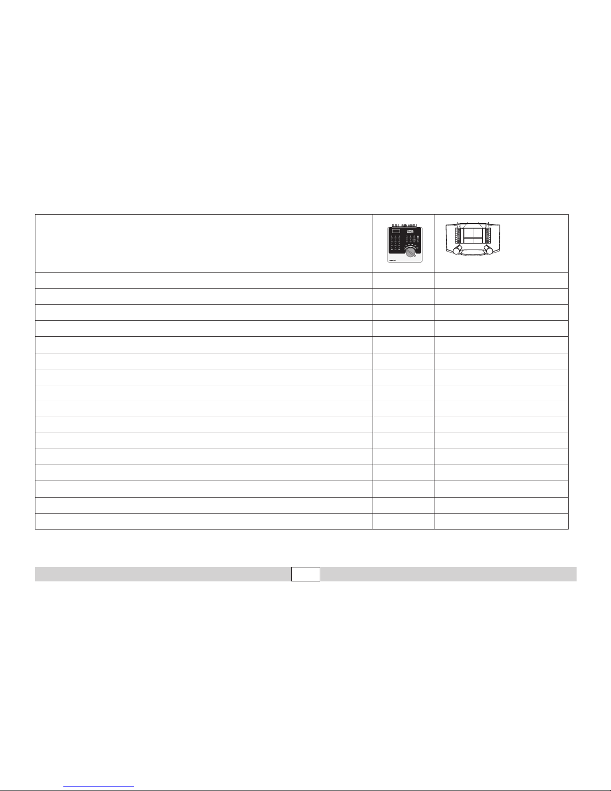
Funzioni commutabili
Digital/Systems
Illuminazione di testa function/off Funzione f0
Solleva/abbassa pantografo f1 (62) Funzione f1 AUX 5, Sound 4
Rumore: rumori di esercizio f2 (62) Funzione f2
Rumore: Fischio f3 (62) Funzione f3 Sound 1
Illuminazione della cabina f4 (62) Funzione f4 AUX 2
Gancio Telex anteriore, con rumore f1 (63) Funzione f5
AUX 3, Sound 12
Fanali di testa anteriori f2 (63) Funzione f6
Gancio Telex posteriore, con rumore f3 (63) Funzione f7
AUX 4, Sound 13
Fanali di testa posteriori f4 (63) Funzione f8
Rumore: stridore dei freni escluso — Funzione f9
ABV, spento — Funzione f10
Rumore: campana — Funzione f11 Sound 3
Fanali di segnalazione — Funzione f12 AUX 1
Rumore: scarico dell‘aria compressa — Funzione f13 Sound 15
Rumore: annuncio di manovra — Funzione f14 Sound 6
Rumore: fischio di manovra — Funzione f15 Sound 2
f0 f8 f0f8
Page 32

32
Betrieb • Operation • Fonctionnement Exploitatie • Operación • Operazione
CV Significato Valore per 6021 Valore DCC
01 Indirizzo 01 – 80 (62)
1 – 127 (3)
CV 29/Bit 5 =0
02 PoM Velocità minima —
0 – 255 (20)
03 PoM Ritardo di avviamento 01 – 63
0 – 255 (15)
04 PoM Ritardo di frenatura 01 – 63
0 – 255 (15)
05 PoM Velocità massima 01 – 63
0 – 255 (245)
08 Ripristino di fabbrica/Identificazione di produzione 08
08 (131)
13 PoM Funzioni F1 - F8 in esercizio analogico —
0 – 255 (0)
14 PoM Funzioni F9 - F15 e luci in esercizio analogico —
0 – 255 (1)
17 Indirizzo ampliato (parte superiore CV29 Bit 5 =1) —
192 – 255 (192)
18 Indirizzo ampliato (parte inferiore CV29 Bit 5 =1) —
0 – 255 (128)
19 Indirizzo di trazione —
0 – 255 (0)
21 PoM Funzioni F1 - F8 durante trazione —
0 – 255 (0)
22 PoM Funzioni F9 - F15 e luci durante trazione —
0 – 255 (0)
27 PoM
Bit 0 = Tratta di frenata accesa/spenta
Bit 4 = comportam. frenatura normale
Bit 5 = comportam. frenatura inverso
—
0, 1, 16, 17, 32,
33, 48, 49
29
Bit 0: Scambio poli senso di marcia
Bit 1: Numero gradazioni di marcia 14 o 28/128
Bit 2: Esercizio DCC con tratta di frenata
Bit 5: Ampiezza indirizzo 7 Bit / 14 Bit
—
0 / 1 (0)*
0 / 2 (2)*
0 / 4 (4)*
0 / 32 (0)*
50 PoM Formati alternativi —
0 – 255 (15)
60 PoM
Annuncio di stazione multiplo
Bit 0 – 3 = numero delle stazioni
Bit 4 = l’ultima stazione fa invertire la sequenza
Bit 5 = la direzione della locomotiva determina la sequenza
Bit 6 = impostazione di base della sequenza
—
0 – 127 (1)
Page 33

33
Betrieb • Operation • Fonctionnement Exploitatie • Operación • Operazione
( ) Valore = impostazione di fabbrica
DCC: programmazione sul binario di programmazione per mezzo della programmazione CV,
programmazione con PoM (Program on the Main); questo deve essere supportato dall’apparato di comando.
* I valori delle impostazioni desiderate si devono addizionare!
Ad es. numero delle gradazioni di marcia 28/128 = 2 + esercizio DCC con tratta di frenatura = 4, determina un valore = 6
CV Significato Valore per 6021 Valore DCC
63 PoM Intensità sonora 01 – 63 (63)
0 – 255 (255)
64 PoM Soglia di frenatura —
0 – 255 (55)
75 Indirizzo 2 (1° indirizzo concatenato) 01 – 80 (63)
—
138
PoM Intensità effetto sonoro „stridore dei freni“ —
0 – 255 (200)
139
PoM Intensità effetto sonoro „rumori di esercizio“ —
0 – 255 (255)
140
PoM Intensità effetto sonoro 1 (fischio) —
0 – 255 (200)
141
PoM Intensità effetto sonoro 2 (fischio di manovra) —
0 – 255 (200)
142
PoM Intensità effetto sonoro 3 (campana) —
0 – 255 (200)
145
PoM Intensità effetto sonoro 6 (annuncio di manovra) —
0 – 255 (200)
151
PoM Intensità effetto sonoro 12 (gancio) —
0 – 255 (128)
152
PoM Intensità effetto sonoro 13 (gancio) —
0 – 255 (128)
153
PoM Intensità effetto sonoro 11 (compressore dell’aria) —
0 – 255 (255)
154
PoM Intensità effetto sonoro 15 (scarico dell‘aria compressa) —
0 – 255 (200)
Page 34

34
Betrieb auf der Anlage • Operation on a layout • Exploitation sur réseau
Bedrijf op een modelbaan • Funcionamiento del sistema • Funzionamento del sistema
Steck- und Ergänzungsteile
Diesem Modell liegen verschiedene Teile bei.
• 2 Stirngeländer als Ersatzteil
• 2 Klauenkupplungen (ohne Telexfunktion)
• 2 Schraubkupplungen (Seite 39).
Mit der Schraubenkupplung können nur
Radien größer 2320 mm befahren werden.
• Luftkessel (zum Austausch gegen den montierten, nur in Verbindung mit der Schraubkupplung).
• Lokführer (nur mit doppelseitigem Klebeband befestigen, keinen Klebstoff verwenden!)
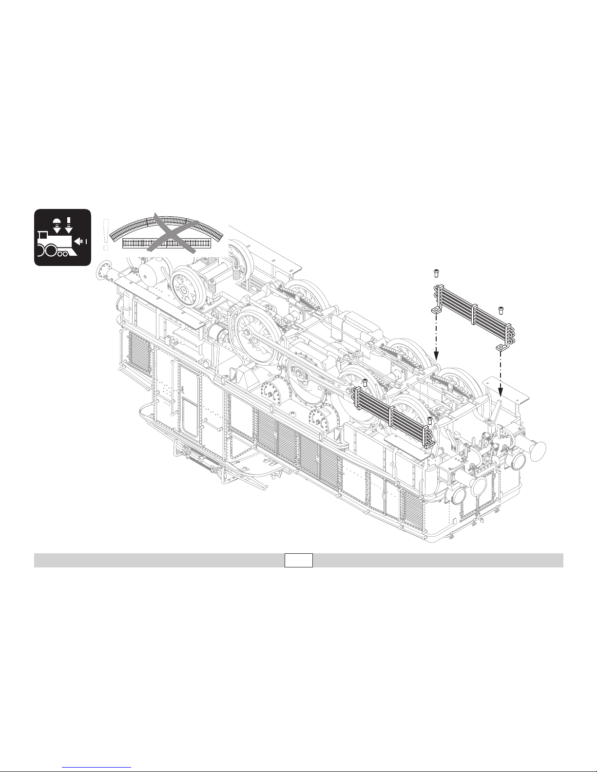
• 2 Kühlschlangen zur Ergänzung, nicht für
den Fahrbetrieb geeignet (Seite 40).
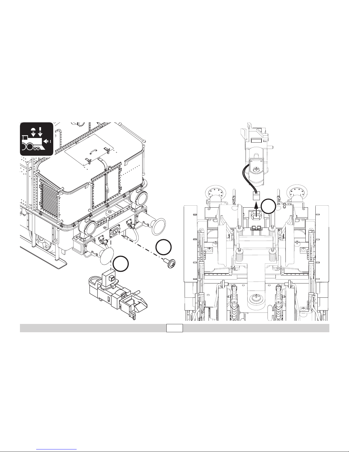
Bei der Demontage der angebauten Telexkupplung darauf achten, dass das Anschlusskabel der Kupplung an der Lok ausgesteckt
werden muss.
Add-On Parts
Different parts are included with this model.
• 2 end handrails as spare parts
• 2 claw couplers (without Telex function)
• 2 reproduction prototype couplers (Page
39).
When using the reproduction prototype coup-
lers the locomotive must be run on curves
greater than 2,320 mm / 92“.
• Air tank (for swapping with the tank already
mounted on the locomotive; only in conjunction with the reproduction prototype
coupler).
• Locomotive engineer (Mount only with
double-sided tape. Do not use cement or
glue!)
• 2 cooling lines only for add-on, not to be
used with the locomotive in operation (Page
40).
When removing the Telex coupler that comes
mounted on the locomotive, make sure that
the connecting wire or cable for the coupler
is unplugged on the locomotive.
Eléments enfichables et complémentaires
Ce modèle est fourni avec différents
éléments.
• 2 garde-corps frontaux comme pièces de
rechange
• 2 attelages à griffes (sans fonction Telex)
• 2 attelages à vis (page 39)
Avec l’attelage à vis, seuls les rayons d’au
moins à 2320 mm permettent une bonne
inscription en courbe.
• Réservoir à air (pour remplacer celui en
place ; uniquement avec l’attelage à vis).
• Mécanicien (à xer uniquement avec de
l’adhésif double-face, ne pas utiliser de
colle !)
• 2 modines de refroidissement en complément, ne conviennent pas pour
l’exploitation (page 40).
Pour le démontage de l’attelage Telex en
place, veillez à débrancher le câble de
raccordement de l’attelage au niveau de la
loco.
Page 35

35
Betrieb auf der Anlage • Operation on a layout • Exploitation sur réseau
Bedrijf op een modelbaan • Funcionamiento del sistema • Funzionamento del sistema
Opsteek- en uitbreidingsdelen
Bij dit model worden verschillende delen
meegeleverd:
• 2 bordessen als vervangingsdeel
• 2 klauwkoppelingen (zonder telex-functie)
• 2 schroefkoppelingen (pag. 39) Met de
schroefkoppelingen kunnen alleen radiussen groter dan 2320 mm bereden worden.
• Luchtketel ( om de gemonteerde te vervangen; alleen bij het gebruik van schroefkoppelingen)
• Machinist ( alleen met dubbelzijdig plakband bevestigen, geen lijm gebruiken!)
• 2 koelslangen als uitbreiding, niet geschikt
voor het rijbedrijf ( pag. 40)
Bij het demonteren van de telexkoppeling er
op letten dat de aansluitkabel van de koppeling op de loc losgenomen moet worden.
Piezas enchufables y complementarias
Se adjuntan a este modelo en miniatura
diferentes piezas.
• 2 barandillas frontales como pieza de
recambio
• 2 enganches de garras (sin función Telex)
• 2 enganches de tornillos (página 39).
• Con el enganche de tornillos se pueden
recorrer radios de curvatura superiores
a 2320 mm.
• Calderín de aire (para sustituir el montado;
solo en combinación con enganche de
tornillos).
• Maquinista (¡sujetar solo con cinta adhesiva
por ambos lados, no emplear pegamento!)
• 2 serpertines de refrigeración como
complemento, no aptos para el servicio de
circulación (página 40).
En el desmontaje del enganche Telex adosado, tener presente que el cable de conexión
del enganche debe desenchufarse de la
locomotora.
Elementi ad innesto e di completamento
A questo modello sono acclusi svariati componenti.
• 2 ringhiere di testa come parti di ricambio
• 2 ganci a uncino (senza funzione Telex)
• 2 ganci a vite (pagina 39).
Con il gancio a vite possono venire percorsi
solo raggi di curve più grandi di 2320 mm.
• Serbatoio dell’aria (per la sostituzione con
quello montato; solo in abbinamento con il
gancio a vite).
• Macchinista (ssare soltanto con nastro
adesivo a doppia faccia, non impiegare
alcun collante!)
• 2 serpentine di raffreddamento per completamento, non adatte per l’esercizio di
marcia (pagina 40).
In caso di smontaggio dell’aggancio Telex
applicato, prestare attenzione al fatto che
il cavetto di collegamento del gancio alla
locomotiva deve venire disinnestato.
Page 36

36
Betrieb auf der Anlage • Operation on a layout • Exploitation sur réseau
Bedrijf op een modelbaan • Funcionamiento del sistema • Funzionamento del sistema
Befahren von Steigungen
Im Gegensatz zum Vorbild können mit einer
Modellbahn auch größere Steigungen
befahren werden. Im Normalfall sollte eine
Steigung bei maximal 3 Prozent liegen. Im Extremfall sind bei entsprechend eingeschränkter Zugleistung maximal 5 Prozent möglich.
Der Anfang und das Ende der Steigung sind
auf jeden Fall auszurunden.
Pflegehinweis
Diese Lok kann auch im Außenbereich
eingesetzt werden. Ein Betrieb bei schlechten
Witterungsbedingungen (Schnee oder Regen)
wird nicht empfohlen.
Antrieb und Elektronik sind gegen Spritzwasser geschützt. Wasserdurchfahrten sind nicht
möglich.
Es wird empfohlen, das Modell nach dem
Betrieb im Außenbereich auf Verschmutzung
zu prüfen und gegebenenfalls trocken mit
Staubtuch oder Pinsel zu reinigen. Nie die Lok
unter fließendem Wasser reinigen.
Hinweis: Reinigungsmittel können die Farbgebung oder die Beschriftung der Lok angreifen
und beschädigen.
Franchissement des côtes
Contrairement à l’original, la maquette est
également en mesure de franchir des côtes
assez importantes. En temps normal, une côte
devrait étre de l’ordre de 3% maximum. A
l’extrême limite, 5% sont envisageables avec
une puissance du train réduite en consequence. Le début et la fin de la côte doivent
en tous cas étre arrondis.
Remarque sur l’entretien
Cette locomotive peut également être mise
en service à l’air libre. Une utilisation par
mauvais temps (neige ou pluie) n’est pas
recommandée.
Le moteur et l’électronique sont protégés
contre les projections d’eau. Des trajets dans
l’eau ne sont pas possibles.
Il est recommandé de vérifier l’encrassement
du modèle après une utilisation à l’extérieur
et, le cas échéant, de nettoyer le modèle à
l’aide d’un chiffon doux ou un pinceau. Ne
jamais nettoyer le modèle au jet d’eau.
Attention : Certains solvants et produits
d’entretien peuvent altérer le marquage et la
peinture du modèle.
Operating the locomotive on grades
In contrast to the prototype a locomotive
on a model railroad can operate up steeper
grades. As a general rule a grade should be
no steeper than 3%. In extreme situations a
maximum grade of 5% is permissible, keeping
in mind that the locomotive’s tractive effort
will be less. The beginning and the end of
the grade must always work gradually up to
maximum grade for the route.
Tips For The Care Of Your Locomotive
This locomotive can also be used outdoors.
We do not recommend running the locomotive
in bad weather (snow or rain).
The mechanism and the electronic circuit
are protected against spraying water. The
locomotive cannot be run through water.
We recommend that you check the locomotive over after running in outdoors and that you
dry it with a cloth or clean in with a brush if
necessary. Never clean the locomotive with
running water.
Important: Cleaning fluids can attack the
finish and lettering for the locomotive and
damage them.
Page 37

37
Betrieb auf der Anlage • Operation on a layout • Exploitation sur réseau
Bedrijf op een modelbaan • Funcionamiento del sistema • Funzionamento del sistema
Berijden van hellingen
In tegenstelling tot het grote voorbeeld kunnen met een
modelbaan ook grotere hellingen bereden
worden. Normaal moet een helling maximaal 3
procent zijn. In extreme gevallen is maximaal
5 procent mogelijk, maar dan moet rekening
gehouden worden met een evenredig verlies
aan vermogen. Het begin en het einde van de
helling moeten altijd gerond worden.
Opmerkingen voor het onderhoud
Deze loc kan ook buiten gebruikt worden. Het
gebruik bij slecht weer (sneeuw of regen) is
niet aan te raden.
Aandrijving en elektronica zijn weliswaar
afgeschermd tegen spatwater maar rijden
door het water is niet mogelijk.
Het is aan te bevelen het model na het gebruik
buiten te controleren op vuil en dit eventueel
droog te verwijderen met een stofdoek of een
zachte kwast. Nooit de loc onder stromend
water reinigen.
Opmerking: reinigingsmiddelen kunnen de
lak en de opschriften op de loc aantasten en
beschadigen.
Percorrenza di pendenze
In contrapposizione al prototipo, con una
ferrovia in miniatura possono venire percorse
anche delle pendenze piuttosto grandi. In
condizioni normali una pendenza dovrebbe
situarsi al massimo sul 3 per cento. In condizioni estreme sono possibili al massimo sul 5
per cento, con corrispondenti prestazioni di
trazione più ridotte. Il principio e la terminazione della pendenza si devono in ogni caso
arrotondare.
Avvertenze di manutenzione
Questa locomotiva può venire impiegata anche in ambienti esterni. Un esercizio in caso
di cattive condizioni meteorologiche (neve
oppure pioggia) non è consigliabile.
Motorizzazione e circuiti elettronici sono
protetti contro gli spruzzi d’acqua. Passaggi
attraverso l’acqua non sono possibili.
Dopo il funzionamento in ambienti esterni è
consigliabile verificare tale modello riguardo
allo sporcamento e se necessario asciugarlo
con un panno per la polvere oppure pulirlo
con un pennello. Non si pulisca mai tale locomotiva sotto l’acqua corrente.
Avvertenza: le sostanze detergenti possono
intaccare e danneggiare la coloritura oppure
le iscrizioni della locomotiva.
Ascenso de rampas
Al contrario que en el modelo real, con un modelo en miniatura es posible circular también
por rampas de mayor inclinación. En situaciones normales, la inclinación máxima de una
rampa se sitúa en el 3 por ciento. En casos
extremos, con una potencia tractora limitada
de manera acorde, es posible ascender una
rampa máxima del 5 por ciento. En todo caso,
debe redondearse el comienzo y el fin de la
rampa.
Consejos para conservación
Esta locomotora puede utilizarse también
en exteriores. No se recomienda el uso en
condiciones meteorológicas desfavorables
(nieve o lluvia). El accionamiento y la electrónica están protegidos contra salpicaduras
de agua. No es posible circular a través de
tramos con agua acumulada.
Tras el uso en exteriores, se recomienda
comprobar si el modelo en miniatura se ha
ensuciado y, en su caso, secarlo con una
bayeta o limpiarlo con un pincel.
Nunca limpiar la locomotora con agua corriente.
Nota: los detergentes pueden atacar y dañar
la pintura o la rotulación de la locomotora.
Page 38
38
Betrieb auf der Anlage • Operation on a layout • Exploitation sur réseau
Bedrijf op een modelbaan • Funcionamiento del sistema • Funzionamento del sistema
40h
Page 39
39
Betrieb auf der Anlage • Operation on a layout • Exploitation sur réseau
Bedrijf op een modelbaan • Funcionamiento del sistema • Funzionamento del sistema
!
Page 40
40
Betrieb auf der Anlage • Operation on a layout • Exploitation sur réseau
Bedrijf op een modelbaan • Funcionamiento del sistema • Funzionamento del sistema
2
1
3
Page 41
41
Betrieb auf der Anlage • Operation on a layout • Exploitation sur réseau
Bedrijf op een modelbaan • Funcionamiento del sistema • Funzionamento del sistema
2
1
3
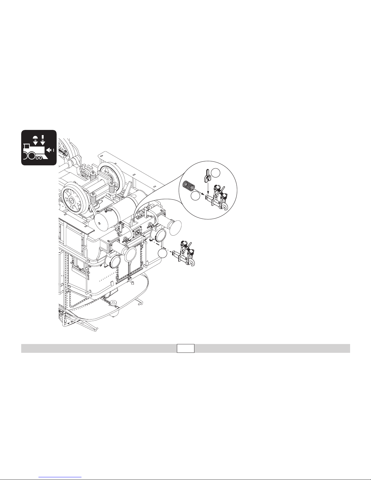
• Mit der Schraubenkupplung können nur
Radien größer 2320 mm befahren werden.
• When using the reproduction prototype
couplers the locomotive must be run on
curves greater than 2,320 mm / 92“.
• Avec l’attelage à vis, seuls les rayons d’au
moins 2320 mm permettent une bonne
inscription en courbe.
• Met de schroefkoppeling kunnen alleen
radiussen groter dan 2320 mm bereden
worden.
• Con el enganche de tornillos se pueden
recorrer radios de curvatura superiores a
2320 mm.
• Con il gancio a vite possono venire percorsi
solo raggi di curve più grandi di 2320 mm.
Page 42

42
Page 43

43
Page 44

www.maerklin.com/en/imprint.html
Gebr. Märklin & Cie. GmbH
Stuttgarter Str. 55 - 57
73033 Göppingen
Germany
www.maerklin.com
270927/1115/Sm1Kb
Änderungen vorbehalten
© Gebr. Märklin & Cie. GmbH
Due to different legal requirements regarding electro-magnetic compatibility,
this item may be used in the USA only after separate certification for FCC compliance and an adjustment if necessary.
Use in the USA without this certification is not permitted and absolves us of any
liability. If you should want such certification to be done, please contact us –
also due to the additional costs incurred for this.
 Loading...