

Page 1
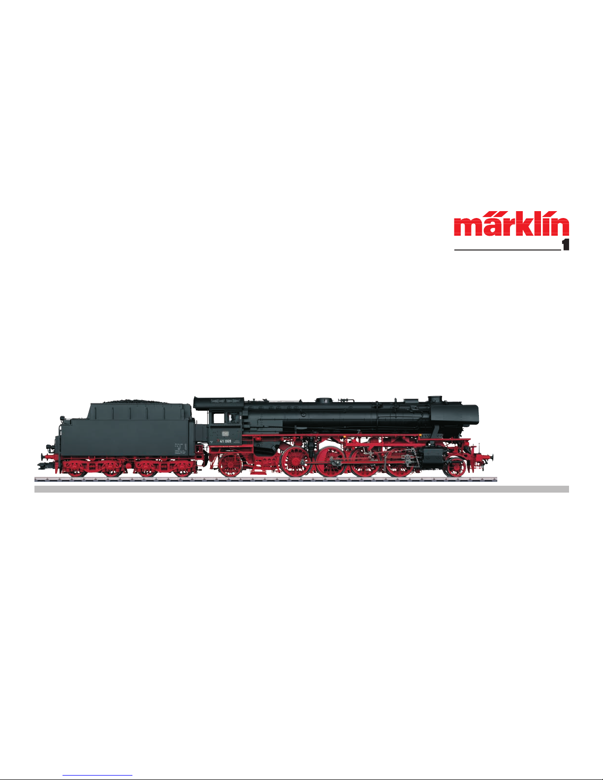
Modell der Schlepptender-Dampflok BR 41
55413
Page 2

2
Inhaltsverzeichnis: Seite
Informationen zum Vorbild 4
Inbetriebnahme 6
Sicherheitshinweise 12
Wichtige Hinweise 12
Funktionen 12
Schaltbare Funktionen 13
Parameter / Register 14
Betrieb auf der Anlage 36
Wartung und Instandhaltung 42
Ersatzteile 44
Table of Contents: Page
Information about the prototype 4
Putting into Operation 6
Safety Notes 16
Important Notes 16
Functions 16
Controllable Functions 17
Parameter / Register 18
Operation on a layout 36
Service and maintenance 42
Spare parts 44
Sommaire : Page
Informations concernant la locomotive réelle
5
Mise en service 6
Remarques importantes sur la sécurité 20
Information importante 20
Fonctionnement 20
Fonctions commutables 21
Paramètre / Registre 22
Exploitation sur réseau 36
Entretien et maintien 42
Pièces de rechange 44
Page 3

3
Indice de contenido: Página
Puesta en servicio 7
Aviso de seguridad 28
Notas importantes 28
Funciones 28
Funciones posibles 29
Parámetro / Registro 30
Funcionamiento del sistema 36
El mantenimiento 42
Recambios 44
Inhoudsopgave: Pagina
Informatie van het voorbeeld 5
Ingebruikname 7
Veiligheidsvoorschriften 24
Belangrijke aanwijzing 24
Functies 24
Schakelbare functies 25
Parameter / Register 26
Bedrijf op een modelbaan 36
Onderhoud en handhaving 42
Onderdelen 44
Indice del contenuto: Pagina
Messa in esercizio 7
Avvertenze per la sicurezza 32
Avvertenze importanti 32
Funzioni 32
Funzioni commutabili 33
Parametro / Registro 34
Exploitation sur réseau 36
Manutenzione ed assistere 42
Pezzi di ricambio 44
Page 4

4
Vorbild • Prototype Exploitation dans le réelle • Grootbedrijf
Informationen zum Vorbild
Die schnellfahrende Güterzuglok der Baureihe 41 gehört zu den späten
Entwicklungen im Einheitslokprogramm der Deutschen Reichsbahn
(DRG). Verschiedene Baugruppen waren identisch mit den etwa gleichzeitig entwickelten Baureihen 06 und 45.
Wie bei anderen Maschinen zeigte auch der St47K-Kessel der BR 41
nach wenigen Jahren Ermüdungserscheinungen, da der Kesselbaustoff nicht alterungsbeständig war und schweißbrüchig wurde. Daher
wurde ab Herbst 1941 zunächst der Kesseldruck auf 16 bar reduziert.
Ferner beschaffte die DRG 1943/44 insgesamt 40 Ersatzkessel, gefertigt
aus dem deutlich beständigeren Kesselbaustoff St34.
Nach dem Zweiten Weltkrieg verblieben 220 Loks bei der DB und 124
bei der Deutschen Reichsbahn (DR) der DDR. Da beide Staatsbahnen
auf die Baureihe 41 nicht verzichten konnten, wurden zahlreiche Maschinen mit neuen Kesseln versehen. Bei der DB wurden 102 Maschinen umgebaut, sie erhielten geschweißte Hochleistungskessel mit
Verbrennungskammer, 40 Maschinen überdies eine Ölhauptfeuerung.
Bei den nicht umgebauten Maschinen konnten durch die Beibehaltung
des gesenkten Kesseldrucks die Kesselschäden in Grenzen gehalten
und mit zwischenzeitlich deutlich verbesserten Schweißtechniken
auch weitgehend behoben werden.
Die Altbaukessel-41er wurden größtenteils in den 1960er-Jahren ausgemustert und nur wenige Loks erlebten 1968 noch die EDV-gerechte
Umzeichnung in die Baureihe 041. Als letzte Maschinen wurden im
September 1970 die 041 253 und 334 beim Bw Köln-Eifeltor abgestellt
und am 27. November 1970 ausgemustert.
Information about the prototype
The class 41 fast freight locomotive was part of the late developments
in the German State Railroad‘s (DRG) standardized locomotive program.
Different components were identical with the classes 06 and 45 developed at about the same time.
As with other locomotives, the St47K boiler on the class 41 exhibited after a few years traces of metal fatigue since this boiler material was not
resistant to aging and became susceptible to breakage at weld points.
For that reason, the boiler pressure was initially reduced to 16 atmospheres or 232 pounds of pressure per square inch starting in the fall of
1941. Furthermore, the DRG purchased a total of 40 replacement boilers
in 1943/44 that were made of the much more durable St34 boiler material.
After World War II, there were 220 locomotives on the DB‘s roster and
124 on the GDR‘s German State Railroad (DR) roster. Since both government railroads could not do without the class 41, numerous units were
equipped with new boilers. On the DB 102 units were rebuilt and equipped with welded, high-performance boiler with a combustion chamber.
Moreover, 40 units were converted to oil firing. On the units not rebuilt
boiler damage could be kept within limits by not exceeding the lowered
boiler pressure. Improved welding techniques in the meantime took care
of the problems for the most part.
The class 41 units with the older design boiler were retired for the most
part in the Sixties and only a few units lasted until the computer renumbering system change to the class 041 in 1968. Road numbers
041 253 and 334 were stored at the maintenance facility at Cologne-Eifeltor in September of 1970 and were retired on November 27, 1970.
Page 5

5
Vorbild • Prototype Exploitation dans le réelle • Grootbedrijf
Informations concernant la locomotive réelle
La locomotive rapide pour trains marchandises de la série 41 compte parmi
les dernières constructions du programme d’unification de la Deutsche
Reichsbahn (DRG). Certains éléments de construction étaient identiques
aux séries 06 et 45 conçues à peu près en même temps.
Au bout de quelques années seulement, la chaudière en St47K de la BR 41
montra - comme pour d’autres machines - des signes de fatigue du fait du
manque de résistance de ce matériau à l’usure qui fragilisait les soudures.
C’est pourquoi la pression de la chaudière fut d’abord réduite à 16 bars à
partir de l’automne 1941. En outre, la DRG fit l’acquisition en 1943/44 d’au
total 40 chaudières de remplacement, fabriquées avec de l’acier St34,
sensiblement plus résistant.
Après la seconde guerre mondiale, 220 locomotives restèrent à la DB et
124 à la DR, en RDA. Les deux sociétés ferroviaires ne pouvant se passer
de la série 41, de nombreuses machines furent pourvues d’une nouvelle
chaudière. A la DB, 102 machines furent transformées et dotées de
chaudières soudées haute performance avec chambre de combustion, 40
unités furent en outre équipées pour la chauffe au fioul. Pour les machines
non transformées, le maintien de la moindre pression permit de limiter les
dégradations de la chaudière et dans une large mesure de les réparer
grâce aux techniques de soudure entre temps nettement améliorées.
Les BR 41 dotées de la chaudière ancien modèle furent en grande partie
réformées dans les années 1960 et seules quelques locos étaient encore
en service en 1968 pour recevoir la nouvelle immatriculation en série 041
conformément aux normes EDV. Les machines 041 253 et 334 furent les
dernières garées en septembre 1970 au dépôt de
Cologne-Eifeltor, puis
réformées le 27 novembre 1970.
Informatie van het voorbeeld
De snelle goederentreinloc van de serie 41 behoort tot de late ontwikkelingen in het eenheidslocprogramma van de Deutsche Reichsbahn
(DRG). Verschillende series waren identiek met de ongeveer gelijktijdig
ontwikkelde series 06 en 45.
Net als bij andere machines vertoonde ook de St47K-ketel van de BR 41
na een aantal jaren tekenen van metaalmoeheid, omdat het ketelbouwmateriaal niet bestand was tegen veroudering en de lasnaden
scheurden. Daardoor werd vanaf de herfst van 1941 eerst de keteldruk
beperkt tot 16 bar. Verder kocht de DRG in 1943/44 in totaal 40 vervangende ketels gemaakt van het duidelijk degelijker ketelbouwmateriaal
St34.
Na de tweede wereldoorlog kwamen 220 locs terecht bij de DB en 124
bij de Deutsche Reichsbahn (DR) in de DDR. Omdat de beide staatsspoorwegen de BR 41 niet konden missen, werden talrijke machines
van nieuwe ketels voorzien. Bij de DB werden 102 machines omgebouwd, die gelaste hoogvermogenketels kregen met een verbrandingskamer, en 40 machines met oliestook. Bij de niet omgebouwde machines
kon door het aanhouden van de lagere keteldruk de schade aan de
ketels binnen de grenzen blijven en met in die tussentijd aanzienlijk
verbeterde lastechnieken ook grotendeels worden opgelost. De 41-ers
met Altbau-ketel werden voor het grootste deel in de jaren 60 buiten
dienst gesteld en slechts weinig locs maakten i n1968 acht nog de
automatiserings-hernoeming mee naar serie 041. Als laatste machines
werden in september 1970 de 041 253 en 334 bij Köln-Eifeltor opgesteld
en op 27 november 1970 buiten dienst gesteld.
Page 6

6
Betrieb • Operation • Fonctionnement Exploitatie • Operación • Operazione
Vor dem ersten Betrieb
Dieses Modell ist hinsichtlich der Technik
und er Ausführung besonders aufwändig und
hochwertig. Die meisten angesteckten oder
verbauten Teile sind aus Metall gefertigt.
Solche Teile können nicht so einfach getauscht werden, wie z.B. Kunststoffteile. Bitte
beachten Sie daher, dass Sie dieses Modell
besonders vorsichtig handhaben sollten.
Für den Tausch von Teilen oder Reparaturen
wenden Sie sich bitte an den Märklin Service.
Hinweise
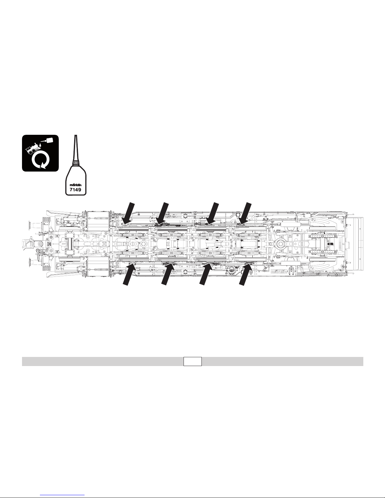
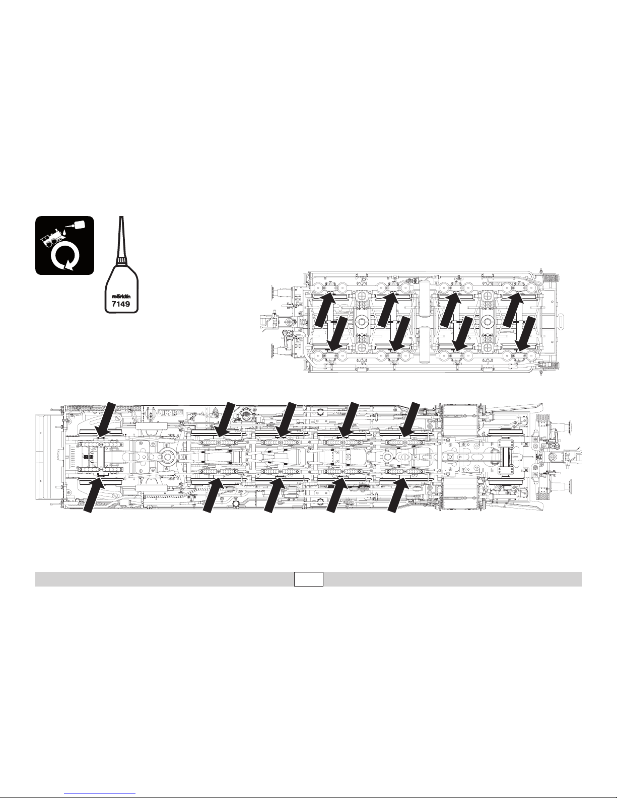
• Das Modell muss vor dem ersten Betrieb
geschmiert werden (siehe Seite 42/43).
• Die Lok kann nicht ohne Tender betrieben
werden. Das Verbindungskabel zwischen
Lok und Tender muss sicher eingesteckt
sein (siehe Seite 10).
• Wenn das Modell mit aktivem Dampfgenerator betrieben wird, so kann ins Besondere
der durch die Zylinder ausströmende Dampf
die Gleise stark verschmutzen.
Before Operating for the First Time
This model is especially complex and costly
in terms of its technology. Most of the applied
parts are constructed of metal. Such parts
cannot be replaced so easily as for example
plastic parts. Please therefore note that you
should handle this model with special care.
Please contact Märklin Service for replacement of parts or for repairs.
Notes
• This model must be lubricated before operating it for the first time (see page 42/43).
• This locomotive cannot be operated without
the tender. The connecting cable between
the locomotive and tender must be plugged
in securely (see page 10).
• When the model is operated with the smoke
generator on, especially the steam flowing
out of the cylinders can dirty up the track
greatly.
Avant la première mise en service
Ce modèle bénéficie d’une technicité de
haut niveau et d‘une finition particulièrement
soignée. La plupart des éléments rapportés
ou intégrés sont en métal. De tels éléments ne
se remplacent pas aussi facilement que des
éléments en plastique par exemple. Veillez
donc à manipuler ce modèle avec un soin
particulier.
Pour les pièces détaillées ou d’éventuelles
réparations, veuillez vous adresser au Service
Märklin.
Remarques
• Le modèle doit être graissé avant sa première mise en service (voir page 42/43)
• La locomotive ne peut pas être exploitée
sans tender. Le câble de raccordement
entre la locomotive et le tender doit être
enfiché correctement (voir page 10)
• Si le modèle est exploité avec un générateur de fumée activé, la vapeur émise – et
particulièrement celle émanant des cylindres – risque d‘encrasser sérieusement la
voie.
Page 7

7
Betrieb • Operation • Fonctionnement Exploitatie • Operación • Operazione
Voor het eerste gebruik
Dit model is vanwege de techniek en de
uitvoering bijzonder uitgewerkt en hoogwaardig uitgevoerd. De meeste opgestoken of
aangebouwde delen zijn van metaal gemaakt.
Dergelijke delen kunnen niet zo eenvoudig
vervangen worden dan kunststof delen. Let
er daarom op dat u het model uitermate voorzichtig behandelt.
Voor het vervangen van delen of reparaties
kunt u zich wenden tot het Märklin service
centrum.
Aanwijzingen
• Het model moet voor het eerste gebruik
gesmeerd worden (zie afb. 42/43)
• De loc kan niet zonder de tender gebruikt
worden. De verbindingskabel tussen loc en
tender moet op de juiste manier ingestoken
zijn (zie afb. 10)
• Als het model met de geactiveerde
dampgenerator gebruikt word, kan in het
bijzonder de door de cilinders uitgestoten
damp de rails sterk vervuilen.
Antes de la primera puesta en servicio
En los aspectos de tecnología incorporada y
ejecución, este modelo en miniatura es muy
sofisticado y avanzado. La mayoría de piezas
enchufadas o incorporadas son de metal.
Tales piezas no se pueden sustituir con la
facilidad de, p. ej., las piezas de plástico. Por
este motivo, tenga presente que debe manejar este modelo con suma precaución.
Para la sustitución de piezas o para reparaciones, diríjase al Servicio de Märklin.
Consejos
• Lubricar el modelo en miniatura antes de la
primera puesta en servicio (véase 42/43).
• No está permitido utilizar la locomotora sin
ténder. El cable de interconexión entre la
locomotora y el ténder debe estar enchufado de modo seguro (véase página 10).
• Si el modelo se utiliza con un generador de
vapor activo, en particular el vapor que sale
de los cilindros puede provocar un fuerte
ensuciamiento de las vías.
Prima del primo funzionamento
Questo modello è particolarmente complicato
e di alto pregio sotto l’aspetto della tecnologia e dell’esecuzione. La maggior parte degli
elementi applicati a innesto o riportati sono
realizzati di metallo. Tali componenti non possono venire sostituiti tanto facilmente, come
ad es. le parti di materiale sintetico. Vogliate
pertanto prestare attenzione, affinché Voi
maneggiate questo modello con particolare
cautela.
Per la sostituzione di componenti oppure
riparazioni, vogliate rivolgerVi al Servizio
Assistenza Märklin.
Avvertenza
• Tale modello deve venire lubricato prima
del primo funzionamento
(si veda pagina 42/43).
• Tale locomotiva non può venire messa in
funzione senza tender. Il cavetto di collegamento tra locomotiva e tender deve essere
innestato in modo sicuro (si veda pagina 10).
• Qualora tale modello venga fatto funzionare
con generatore di vapore attivo, specialmente quel vapore che defluisce attraverso
i cilindri può allora imbrattare fortemente i
binari.
Page 8

8
Betrieb • Operation • Fonctionnement Exploitatie • Operación • Operazione
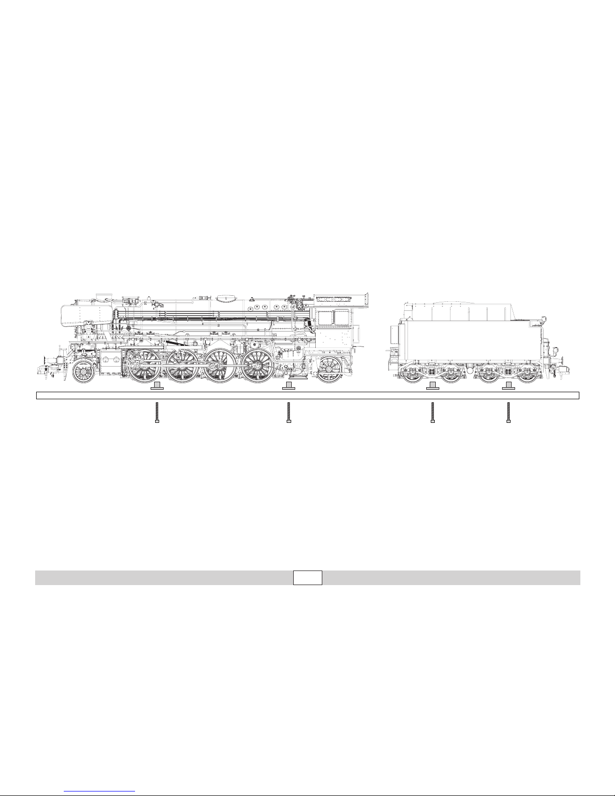
Für den sicheren Transport wurde dieses
schwere Modell auf dem Sockel angeschraubt. Bitte transportieren Sie dieses
Modell nur trocken und so gesichert und in
der Originalkassette.
Beachten Sie, dass der Tender nach entfernen der Sicherungsschrauben auf dem
Stellbrett frei rollen kann und gegen Absturz
gesichert werden muss.
This heavy model was bolted to the base for
safe transport. Please transport this model
only when it is dry and secured as described
in preceding sentence and in the original box.
Please note that the tender can roll free after
removing the mounting bolts on the base, and
it must therefore be protected against falling
and crashing.
Afin d’éviter tout problème lié au transport, ce
modèle lourd a été vissé sur son socle. Veillez
à le transporter uniquement sous cette condition, au sec et dans son boîtier d’origine.
Notez qu’une fois la vis de sécurité enlevée,
le tender peut rouler librement sur la planche
et qu‘il faut donc prévenir le risque de chute.
Voor een veilig transport is het model op een
sokkel vast geschroefd. Transporteer het
model a.u.b. alleen droog en vastgeschroefd
in de originele cassette.
Let er op dat de tender na het verwijderen
van de transportschroeven, op de sokkel vrij
kan rollen en vastgehouden moet worden om
vallen te voorkomen.
Para hacer posible un transporte seguro, se
ha atornillado este pesado modelo al zócalo.
Transporte este modelo en miniatura siempre
seco y bien asegurado y en su casete original.
Asegúrese de que el ténder, tras retirar los
tornillos inmovilizadores, pueda rodar libremente sobre el pupitre de la maqueta y de
protegerlo contra el vuelco.
Per un trasporto sicuro questo pesante modello è stato fissato con viti al basamento. Si
prega di trasportare questo modello soltanto
asciutto e così assicurato, e nella cassetta
originale.
Prestate attenzione al fatto che il tender, dopo
la rimozione delle viti di fissaggio sulla tavo-
letta di appoggio, può correre liberamente e
deve venire assicurato contro la caduta.
Page 9
9
Betrieb • Operation • Fonctionnement Exploitatie • Operación • Operazione
Page 10
10
Betrieb • Operation • Fonctionnement Exploitatie • Operación • Operazione
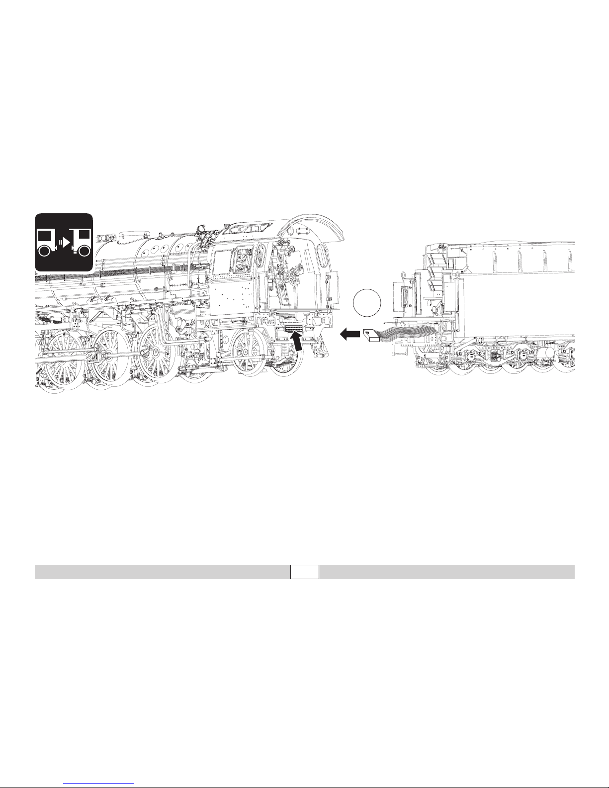
1
Hinweis: Das Verbindungskabel zwischen
Lok und Tender darf nur im spannungslosen
Zustand eingesteckt werden. Stellen Sie die
Fahrzeuge dazu auf ein abgeschaltetes Gleis
oder schalten Sie die Anlage vorher ab.
Note: The connecting cable between the
locomotive and tender may be plugged in only
when there is no voltage present or on. To
do this, place the locomotive and tender on a
length of track with no power in it or shut the
layout off before doing this.
Remarque : Le câble de raccordement entre
la locomotive et le tender doit être branché
hors tension uniquement. Pour cela, placez
les véhicules sur un rail non alimenté ou
débranchez au préalable l’installation.
Nota: Está permitido enchufar el cable de
interconexión entre locomotora y ténder
únicamente sin tensión eléctrica presente.
Para tal fin, coloque los vehículos en una
vía con la alimentación eléctrica apagada o
apague previamente el suministro eléctrico a
la maqueta de trenes.
Avvertenza: Il cavetto di collegamento tra
locomotiva e tender deve venire innestato
solamente nella condizione di assenza di
tensione. A tale scopo vogliate collocare i
rotabili sopra un binario disattivato oppure in
precedenza disattivate l’impianto.
Opmerking: De verbindingskabel tussen loc
en tender mag alleen in spanningsloze
toestand er in gestoken worden. Zet het
voertuig hiervoor op een afgeschakeld spoor
of schakel de gehele baan voordien uit.
Page 11
11
Betrieb • Operation • Fonctionnement Exploitatie • Operación • Operazione
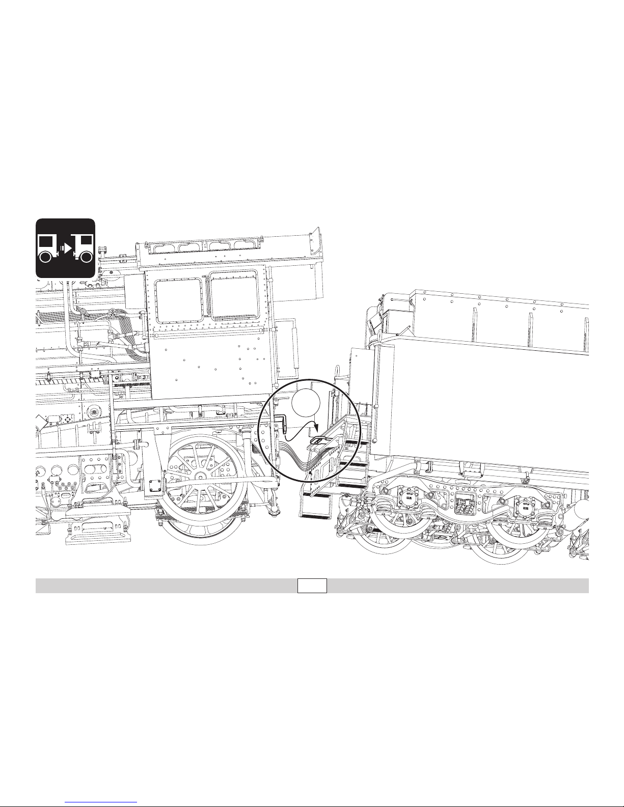
2
Page 12

12
Betrieb • Operation • Fonctionnement Exploitatie • Operación • Operazione
Sicherheitshinweise
• Die Lok darf nur mit einem dafür bestimmten Betriebssystem
(Gleichstrom [DC] = max 18V±, Märklin Wechselstrom,
Märklin Digital oder Märklin Systems) eingesetzt werden.
• Nur Schaltnetzteile/Transformatoren verwenden, die Ihrer örtlichen
Netzspannung entsprechen.
• Die Lok darf nur aus einer Leistungsquelle versorgt werden.
• Beachten Sie unbedingt die Sicherheitshinweise in der Bedienungs-
anleitung zu Ihrem Betriebssystem.
• Für den konventionellen Betrieb der Lok muss das Anschlussgleis
entstört werden. Dazu ist das Entstörset 104770 zu verwenden. Für
Digitalbetrieb ist das Entstörset nicht geeignet.
• Das verwendete Gleisanschlusskabel darf maximal 2 Meter lang sein.
• Setzen Sie das Modell keiner direkten Sonneneinstrahlung, starken
Temperaturschwankungen oder hoher Luftfeuchtigkeit aus.
• ACHTUNG! Funktionsbedingte scharfe Kanten und Spitzen.
• Verbaute LED`s entsprechen der Laserklasse 1 nach Norm EN 60825-1.
Wichtige Hinweise
• Wegen der hohen Leistungsaufnahme dieser Lokomotive ist der
Betrieb mit der Mobile Station 60652 nur eingeschränkt möglich.
• Die Bedienungsanleitung ist Bestandteil des Produktes und muss
deshalb aufbewahrt sowie bei Weitergabe des Produktes mitgegeben werden.
• Für Reparaturen oder Ersatzteile wenden Sie sich bitte an Ihren
Märklin-Fachhändler.
•
Gewährleistung und Garantie gemäß der beiliegenden Garantieurkunde.
• Entsorgung: www.maerklin.com/en/imprint.html
Funktionen
•
Die Betriebsart (AC/DC, Mfx, Märklin-Motorola oder DCC) wird
automatisch erkannt.
• Mfx-Technologie für Mobile Station / Central Station.
Name ab Werk: 41 069
• Einstellbare Adressen:
1-80 (Control Unit 6021)
1-255 (Central Station 6021x)
01 – 9999 DCC
• Adresse ab Werk: (Märklin) 40 & 41 / (DCC) 3
• Einstellen der Lokparameter (Adresse, Anfahr-/Bremsverzögerung,
Höchstgeschwindigkeit usw.): mit Control Unit und DCC (CV Pro-
grammierung), Mobile Station oder Central Station.
• Fahrtrichtungsabhängige Stirnbeleuchtung.
• Bei eingeschaltetem Rauch sind einzelne Rauchfunktionen zusam-
men mit den Geräuschfunktionen auslösbar (siehe Seite 39).
• Im Fahrbetrieb wird die Steuerstange auf der rechten Seite der Lok
über einen Motor vorbildgerecht in 5 Stellungen verstellt.
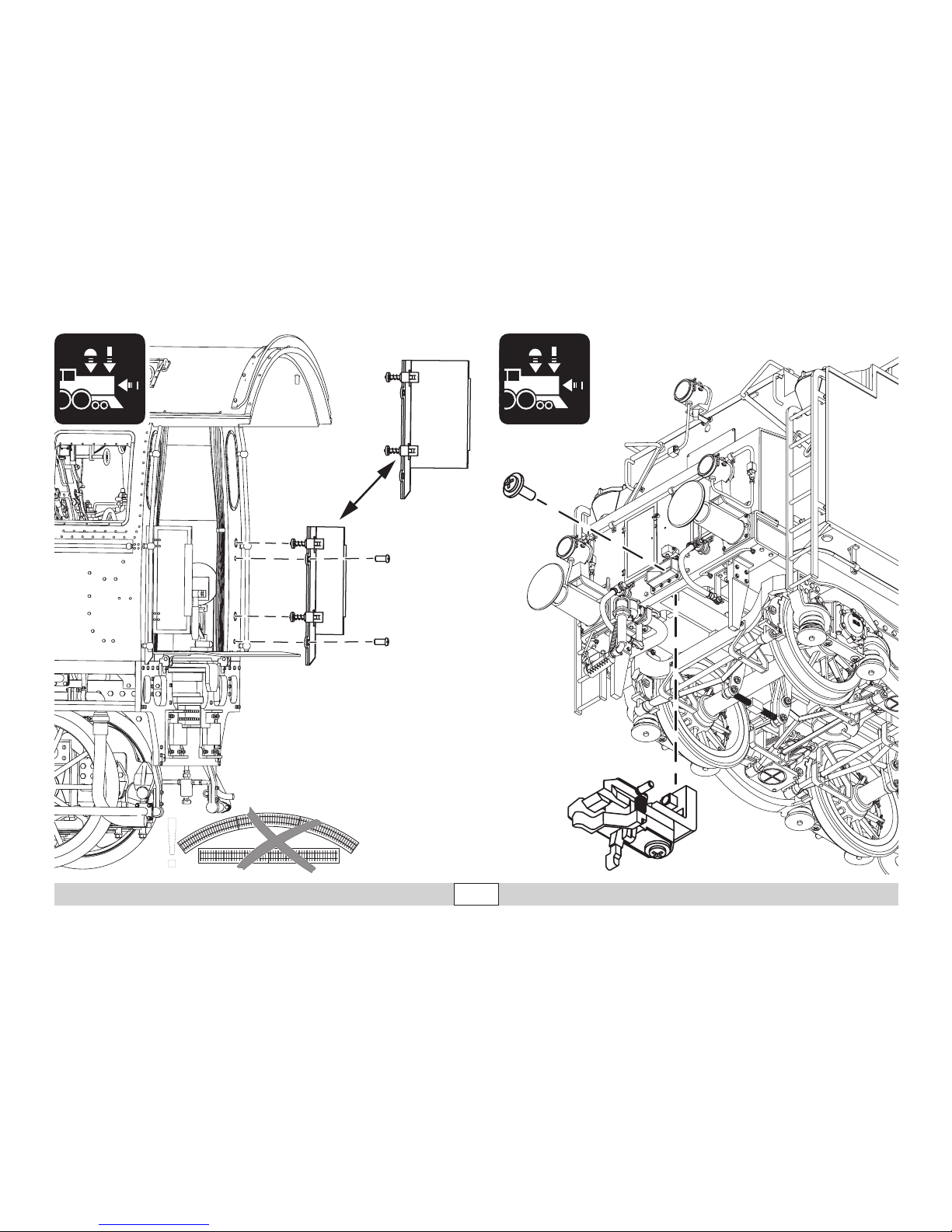
• Die Türen an Lok und Tender können durch die beiliegenden Türen
ersetzt werden (S. 36). Durch die größeren können Probleme im
Fahrbetrieb entstehen.
• Das Modell ist für den Betrieb auf Märklin 1-Gleisen entwickelt. Ein
Betrieb auf anderen Gleissystemen geschieht auf eigenes Risiko.
• Befahrbarer Mindestradius: 1020 mm
• Im Analogbetrieb stehen nur die Fahr- und Lichtwechselfunktionen
zur Verfügung.
Page 13
13
Betrieb • Operation • Fonctionnement Exploitatie • Operación • Operazione
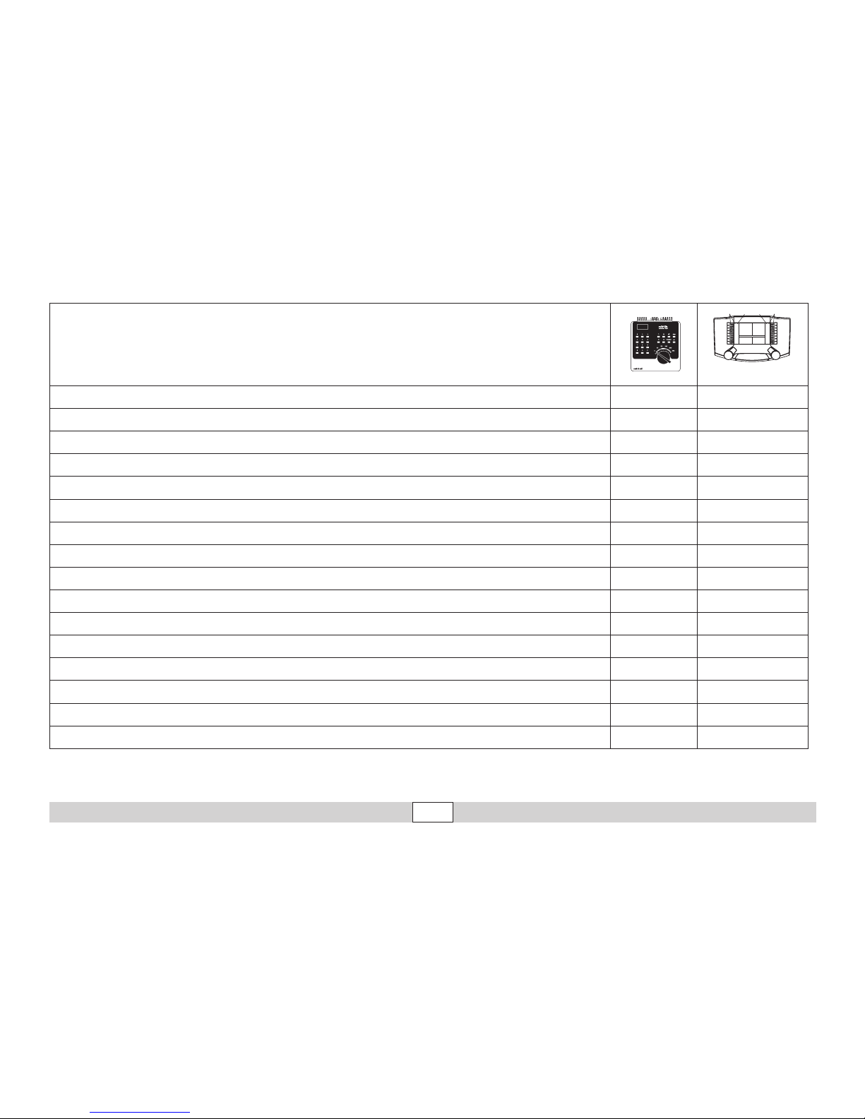
Schaltbare Funktionen
Digital/Systems
Spitzensignal function/off Funktion f0
Rauchgenerator (40) f1 Funktion f1
Betriebsgeräusch (40) f2 Funktion f2
Geräusch & Dampf
1
: Pfeife (40) f3 Funktion f3
Telex-Kupplung (40) f4 Funktion f4
Führerstandsbeleuchtung (41) f1 Funktion f5
Triebwerksbeleuchtung (41) f2 Funktion f6
Geräusch & Dampf: Rangierpff (41) f3 Funktion f7
ABV, aus (41) f4 Funktion f8
Geräusch: Bremsenquietschen aus — Funktion f9
Geräusch: Kohle schaufeln — Funktion f10
Geräusch: Kipprost — Funktion f11
Geräusch: Luftpumpe — Funktion f12
Geräusch: Injektor — Funktion f13
Geräusch: Wasserpumpe — Funktion f14
Geräusch & Dampf
1, 2
: Zylinder ausblasen — Funktion f15
f0 f8 f0f8
1
nur in Verbindung mit F1
2
nur wenn Taste länger gedrückt bleibt
Page 14

14
Betrieb • Operation • Fonctionnement Exploitatie • Operación • Operazione
CV Bedeutung Wert für 6021 Wert DCC
01 Adresse 01 – 80 (40)
1 – 127 (3)
CV 29/Bit 5 =0
02 PoM Minimalgeschwindigkeit — 0 – 255 (20)
03 PoM Anfahrverzögerung 01 – 63 0 – 255 (15)
04 PoM Bremsverzögerung 01 – 63 0 – 255 (15)
05 PoM Maximalgeschwindigkeit 01 – 63 0 – 255 (250)
08 Werkreset/Herstellerkennung 08 08 (131)
13 PoM Funktionen F1 - F8 im Analogbetrieb — 0 – 255 (0)
14 PoM Funktionen F9 - F15 und Licht im Analogbetrieb — 0 – 255 (1)
17 Erweiterte Adresse (oberer Teil CV29 Bit 5 =1) — 192 – 255 (192)
18 Erweiterte Adresse (unterer Teil CV29 Bit 5 =1) — 0 – 255 (128)
19 Traktionsadresse — 0 – 255 (0)
21 PoM Funktionen F1 - F8 bei Traktion — 0 – 255 (0)
22 PoM Funktionen F9 - F15 und Licht bei Traktion — 0 – 255 (0)
27 PoM
Bit 4 = normales Bremsverhalten
Bit 5 = inverses Bremsverhalten
— 0, 16, 32, 48 (48)
29 PoM
Bit 0: Umpolung Fahrtrichtung
Bit 1: Anzahl Fahrstufen 14 oder 28/128
Bit 2: Analogbetrieb ein/aus
Bit 5: Adressumfang 7 Bit / 14 Bit
—
0 / 1 (0)*
0 / 2 (2)*
0 / 4 (4)*
0 / 32 (0)*
50 PoM DC Vmax — 0 – 255 (255)
60 PoM
Multibahnhofsansage
Bit 0 – 3 = Anzahl der Bahnhöfe
Bit 4 = letzter Bahnhof kehrt Reihenfolge um
Bit 5 = Lokrichtung bestimmt Reihenfolge
Bit 6 = Reihenfolge Grundeinstellung
— 0 – 127 (1)
Page 15

15
Betrieb • Operation • Fonctionnement Exploitatie • Operación • Operazione
( ) Werte = Werkseinstellung
DCC: programmieren auf dem Programmiergleis mittels CV Programmierung,
programmieren mit PoM (Program on the Main); dies muss vom Steuergerät unterstützt werden.
* Die Werte der gewünschten Einstellungen sind zu addieren!
Z.B. Anzahl der Fahrstufen 28/128 = 2 + DCC Betrieb mit Bremsstrecke = 4, ergibt Wert = 6
CV Bedeutung Wert für 6021 Wert DCC
63 PoM Lautstärke 01 – 63 (63) 0 – 255 (255)
64 PoM Bremsschwelle 0 – 255 (255)
75 Adresse 2 (1. Folgeadresse) 01 – 80 (41) —
138 PoM Lautstärke Sound „Bremsenquietschen“ — 0 – 255 (255)
139 PoM Lautstärke Sound „Betriebsgeräusch“ — 0 – 255 (255)
140 PoM Lautstärke Sound 1 (Pfeife) — 0 – 255 (255)
141 PoM Lautstärke Sound 2 (Rangierpfiff) — 0 – 255 (255)
146 PoM Lautstärke Sound 7 (Wasserpumpe) — 0 – 255 (255)
147 PoM Lautstärke Sound 8 (Pfeife) — 0 – 255 (255)
148 PoM Lautstärke Sound 9 (Kohle schaufeln) — 0 – 255 (255)
149 PoM Lautstärke Sound 10 (Kipprost) — 0 – 255 (255)
150 PoM Lautstärke Sound 11 (Luftpumpe) — 0 – 255 (255)
151 PoM Lautstärke Sound 12 (Injektor) — 0 – 255 (255)
152 PoM Lautstärke Sound 13 (Zylinder ausblasen) — 0 – 255 (255)
Page 16

16
Betrieb • Operation • Fonctionnement Exploitatie • Operación • Operazione
• The warranty card included with this product species the warranty
conditions.
• Disposing: www.maerklin.com/en/imprint.html
Functions
• The mode of operation (AC/DC, Mfx, Märklin Motorola, or DCC) is
recognized automatically.
• Mfx technology for the Mobile Station / Central Station.
Name set at the factory: 41 069
• Possible addresses:
1-80 (Control Unit 6021)
1-255 (Central Station 6021x)
01 – 9999 DCC
• Address set at the factory: (Märklin) 40 & 41 / (DCC) 3
• Setting locomotive parameters (address, acceleration/braking delay,
maximum speed, etc.): with the Control Unit and DCC (CV program-
ming), Mobile Station, or the Central Station.
• Headlights, changing over with the direction of travel.
• Individual smoke functions can be activated with the sound func-
tions when the smoke is turned on (see page 39).
• When the locomotive is running, the control rod on the right side of the
locomotive is shifted prototypically in 5 positions by means of a motor.
• The doors on the locomotive and the tender can be replaced by doors included with the model (Page 36). The larger doors may cause
problems when the locomotive is running.
• The model is designed for operation on Märklin 1 Gauge track. As the
consumer you assume the risk for operating on other makes of track.
• Minimum radius for operation: 1020 mm / 40-1/6“.
• Only the train control functions and headlight changeover feature
are available in analog operation.
Safety Notes
• This locomotive is to be used only with an operating system designed for it (DC power = 18V±, Märklin AC, Märklin Digital,
Märklin Systems).
• Use only switched mode power supply units and transformers that
are designed for your local power system.
• This locomotive must never be supplied with power from more than
one transformer.
• Pay close attention to the safety notes in the instructions for your
operating system.
• The feeder track must be equipped to prevent interference with
radio and television reception, when the locomotive is to be run in
conventional operation. The 104770 interference suppression set is
to be used for this purpose.
• The wire used for feeder connections to the track may only be a
maximum of 2 meters / 78 inches long.
• Do not expose the model to direct sunlight, extreme changes in
temperature, or high humidity.
• WARNING! Sharp edges and points required for operation.
• The LEDs in this item correspond to Laser Class 1 according to Stan-
dard EN 60825-1.
Important Notes
• Due to the high power requirements for this heavy locomotive, there
are only limited possibilities for operation with the 60652 Mobile Station.
• The operating instructions are a component part of the product and must
therefore be kept as well as transferred along with the product to others.
• Please see your authorized Märklin dealer for repairs or spare parts.
Page 17
17
Betrieb • Operation • Fonctionnement Exploitatie • Operación • Operazione
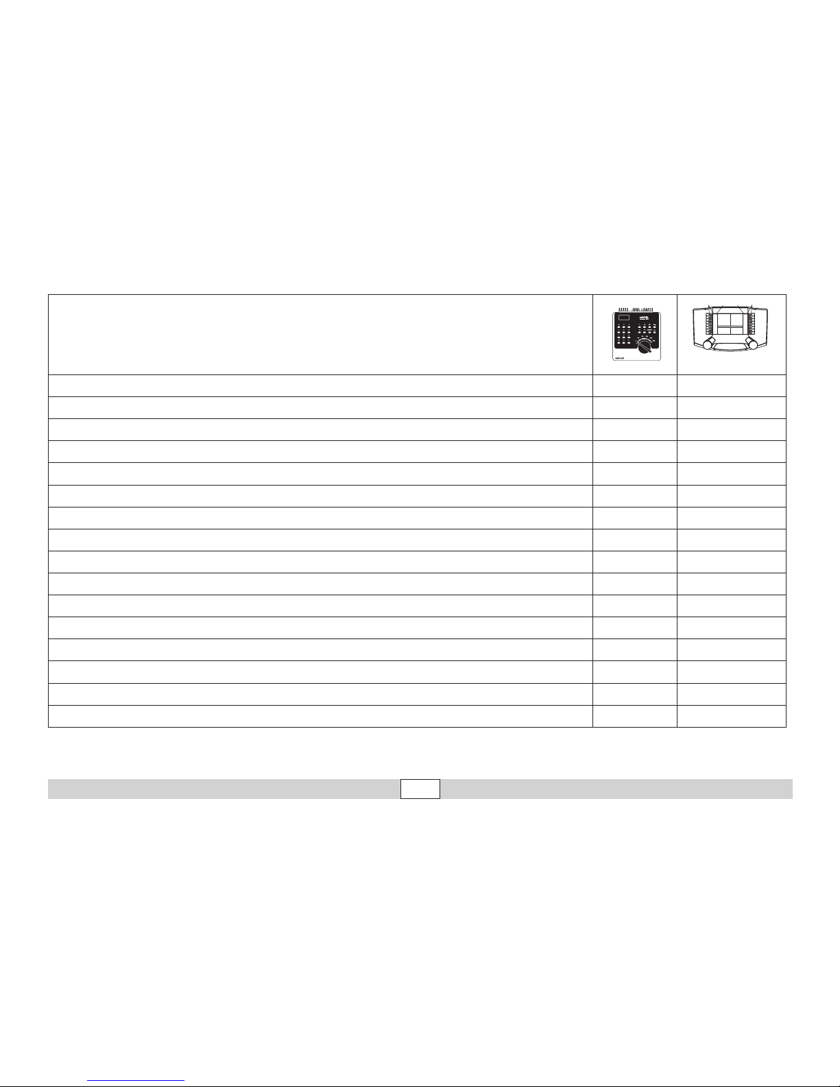
Controllable Functions
Digital/Systems
Headlights function/off Function f0
Smoke generator (40) f1 Function f1
Operating sounds (40) f2 Function f2
Sound effect & steam
1
: whistle blast (40) f3 Function f3
Telex coupler (40) f4 Function f4
Engineer‘s cab lighting (41) f1 Function f5
Running gear lights (41) f2 Function f6
Sound effect & steam: Switching whistle (41) f3 Function f7
ABV; OFF (41) f4 Function f8
Sound effect: Squealing brakes off — Function f9
Sound effect: Coal being shoveled — Function f10
Sound effect: Ash grate — Function f11
Sound effect: Air pump — Function f12
Sound effect: Injector — Function f13
Sound effect: Water pump — Function f14
Sound effect & steam
1, 2
: Blowing out cylinders — Function f15
f0 f8 f0f8
1
only in conjunction with F1
2
only when the button is pressed down longer
Page 18

18
Betrieb • Operation • Fonctionnement Exploitatie • Operación • Operazione
CV Discription 6021 Value DCC Value
01 Address 01 – 80 (40)
1 – 127 (3)
CV 29/Bit 5 =0
02 PoM Minimum Speed — 0 – 255 (20)
03 PoM Acceleration delay 01 – 63 0 – 255 (15)
04 PoM Braking delay 01 – 63 0 – 255 (15)
05 PoM Maximum speed 01 – 63 0 – 255 (250)
08 Factory Reset / Manufacturer Recognition 08 08 (131)
13 PoM Functions F1 - F8 in analog operation — 0 – 255 (0)
14 PoM Functions F9 - F15 and lights in analog operation — 0 – 255 (1)
17 Extended address (upper part CV29 Bit 5 = 1) — 192 – 255 (192)
18 Extended address (lower part CV29 Bit 5 = 1) — 0 – 255 (128)
19 Multiple Unit Address — 0 – 255 (0)
21 PoM Functions F1 - F8 on Multiple Unit — 0 – 255 (0)
22 PoM Functions F9 - F15 and lights on Multiple Unit — 0 – 255 (0)
27 PoM
Bit 4 = Normal braking behavior
Bit 5 = Inverse braking behavior
— 0, 16, 32, 48 (48)
29 PoM
Bit 0: Reversing direction
Bit 1: Number of speed levels 14 or 28/128
Bit 2: analog operation on/off
Bit 5: Address length 7 Bit / 14 Bit
—
0 / 1 (0)*
0 / 2 (2)*
0 / 4 (4)*
0 / 32 (0)*
50 PoM DC Vmax — 0 – 255 (255)
60 PoM
Multiple station announcements
Bit 0 – 3 = Number of stations
Bit 4 = Last station reverses the sequence.
Bit 5 = Locomotive direction determines the sequence.
Bit 6 = Basic setting for sequence.
— 0 – 127 (1)
Page 19

19
Betrieb • Operation • Fonctionnement Exploitatie • Operación • Operazione
( ) Values = factory settings
DCC: programming on the programming track by means of CV programming,
programming with PoM (Program on the Main); this must be supported by the controller you are using.
* The values for the desired setting must be added!
Example: The number of speed levels 28/128 = 2 + DCC operation with a braking route = 4, results in the value = 6
CV Discription 6021 Value DCC Value
63 PoM Volume 01 – 63 (63) 0 – 255 (255)
64 PoM Brake threshold 0 – 255 (255)
75 Address 2 (1st consecutive address) 01 – 80 (41) —
138 PoM Volume for sound "squealing brakes" — 0 – 255 (255)
139 PoM Volume for sound "operating sounds" — 0 – 255 (255)
140 PoM Volume for sound 1 (whistle) — 0 – 255 (255)
141 PoM Volume for sound 2 (Switching whistle) — 0 – 255 (255)
146 PoM Volume for sound 7 (Water pump) — 0 – 255 (255)
147 PoM Volume for sound 8 (whistle) — 0 – 255 (255)
148 PoM Volume for sound 9 (Coal being shoveled) — 0 – 255 (255)
149 PoM Volume for sound 10 (Ash grate) — 0 – 255 (255)
150 PoM Volume for sound 11 (Air pump) — 0 – 255 (255)
151 PoM Volume for sound 12 (Injector) — 0 – 255 (255)
152 PoM Volume for sound 13 (Blowing out cylinders) — 0 – 255 (255)
Page 20

20
Betrieb • Operation • Fonctionnement Exploitatie • Operación • Operazione
Remarques importantes sur la sécurité
• La locomotive ne peut être mise en service qu’avec un système
d’exploitation adéquat (DC = 18V ±, Märklin AC, Märklin Digital ou
Märklin Systems).
• Utiliser uniquement des convertisseurs et transformateurs correspondant à la tension du secteur local.
• La locomotive ne peut être alimentée en courant que par une seule
source de courant.
• Veuillez impérativement respecter les remarques sur la sécurité
décrites dans le mode d’emploi de votre système d’exploitation.
• Pour l’exploitation de la locomotive en mode conventionnel, la voie
de raccordement doit être déparasitée. A cet effet, utiliser le set de
déparasitage réf. 104770. Le set de déparasitage ne convient pas
pour l’exploitation en mode numérique.
• Le câble de raccordement à la voie utilisé ne doit en aucun cas
dépasser deux mètres.
• Ne pas exposer le modèle à un ensoleillement direct, à de fortes
variations de température ou à un taux d‘humidité important.
• ATTENTION! Pointes et bords coupants lors du fonctionnement du
produit.
• Les DEL installées correspondent à la classe laser 1 selon la
norme EN 60825-1.
Information importante
• Du fait de l’importance de la puissance absorbée de cette locomotive,
l’exploitation avec la Mobile Station 60652 n’est possible que dans certaines limites.
• La notice d‘utilisation font partie intégrante du produit ; ils doivent donc
être conservés et, le cas échéant, transmis avec le produit.
• Pour toute réparation ou remplacement de pièces, adresses-vous à
votre détaillant-spécialiste Märklin.
• Garantie légale et garantie contractuelle conformément au certicat
de garantie ci-joint.
• Elimination : www.maerklin.com/en/imprint.html
Fonctionnement
• Le mode d’exploitation (AC/DC, Mfx, Märklin-Motorola ou DCC) est
identifié automatiquement.
• Technologie mfx pour Mobile Station / Central Station.
Nom encodée en usine : 41 069
• Adresses pouvant être paramétrées :
1-80 (Control Unit 6021)
1-255 (Central Station 6021x)
01 – 9999 DCC
• Adresse départ usine : (Märklin) 40 & 41 / (DCC) 3
• Paramétrer les paramètres des locomotives (adresse, retardement
au démarrage / au freinage, vitesse maximale etc.) avec Control Unit
et DCC (programmation CV), Mobile Station ou Central Station.
• Feux de signalisation avec inversion selon sens de marche.
• Une fois le générateur de fumée activé, les différentes fonctions
peuvent être déclenchées avec les fonctions sonores (voir page 39).
•
En mode d’exploitation, la bielle de commande est déplacée de manière
réaliste par un moteur sur le côté droit de la loco selon cinq positions.
• Les portes de la loco et du tender peuvent être remplacées par les
portes fournies (page 36), mais celles-ci peuvent être à l’origine de
problèmes importants lors de l’exploitation.
• Le modèle réduit est conçu pour rouler sur des voies Märklin 1. Le
faire rouler sur des voies d’autres systèmes comporte des risques.
• Rayon minimal d’inscription en courbe: 1020 mm.
• En mode d’exploitation analogique, seules les fonctions relatives à la
conduite et à l‘inversion des feux sont disponibles.
Page 21
21
Betrieb • Operation • Fonctionnement Exploitatie • Operación • Operazione
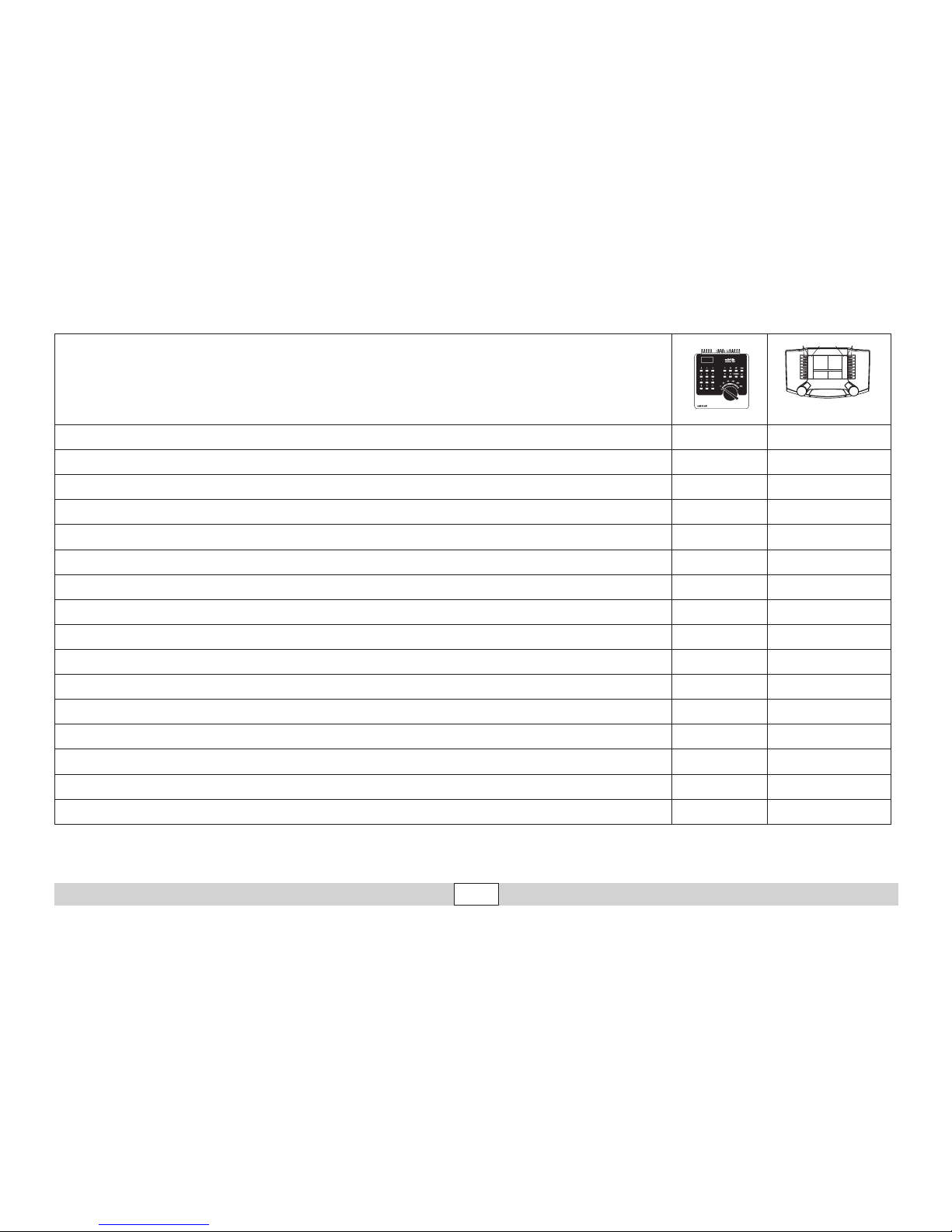
Fonctions commutables
Digital/Systems
Fanal function/off Fonction f0
Générateur de fumée (40) f1 Fonction f1
Bruit d’exploitation (40) f2 Fonction f2
Bruitage & vapeur
1
: sifet (40) f3 Fonction f3
Attelage Telex (40) f4 Fonction f4
Eclairage de la cabine de conduite (41) f1 Fonction f5
Eclairage du mécanisme moteur (41) f2 Fonction f6
Bruitage & vapeur : Sifet pour manœuvre (41) f3 Fonction f7
ABV, désactivé (41) f4 Fonction f8
Bruitage : Grincement de freins désactivé — Fonction f9
Bruitage : Pelletage du charbon — Fonction f10
Bruitage : Grille basculante — Fonction f11
Bruitage : Compresseur — Fonction f12
Bruitage : Injecteur — Fonction f13
Bruitage : Pompe à eau — Fonction f14
Bruitage & vapeur
1, 2
: Purge des cylindres — Fonction f15
f0 f8 f0f8
1
Uniquement en combinaison avec F1
2
Uniquement lorsque la touche reste enfoncée un certain temps
Page 22

22
Betrieb • Operation • Fonctionnement Exploitatie • Operación • Operazione
CV Affectation 6021 Valeur DCC Valeur
01 Adresse
01 – 80 (40)
1 – 127 (3)
CV 29/Bit 5 =0
02 PoM Vitesse minimale
— 0 – 255 (20)
03 PoM Temporisation d‘accélération
01 – 63 0 – 255 (15)
04 PoM Temporisation de freinage
01 – 63 0 – 255 (15)
05 PoM Vitesse maximale
01 – 63 0 – 255 (250)
08 Réinitialisation d’usine/identification du fabricant
08 08 (131)
13 PoM Fonctions F1 - F8 en mode analogique
— 0 – 255 (0)
14 PoM Fonctions F9 - F15 et éclairage en mode analogique
— 0 – 255 (1)
17 Adresse étendue (partie supérieure CV29 Bit 5 = 1)
— 192 – 255 (192)
18 Adresse étendue (partie inférieure CV29 Bit 5 = 1)
— 0 – 255 (128)
19 Adresse traction
— 0 – 255 (0)
21 PoM Fonctions F1 - F8 pour traction
— 0 – 255 (0)
22 PoM Fonctions F9 - F15 et éclairage traction
— 0 – 255 (0)
27 PoM
Bit 4 = caractéristiques de freinage normales
Bit 5 = caractéristiques de freinage inverses
— 0, 16, 32, 48 (48)
29 PoM
Bit 0 : Inv. polarité Sens de marche
Bit 1 : Nombre de crans de marche 14 ou 28/128
Bit 2 : mode analogique
Bit 5 : Capacité d’adresses 7 Bit / 14 Bit
—
0 / 1 (0)*
0 / 2 (2)*
0 / 4 (4)*
0 / 32 (0)*
50 PoM DC Vmax
— 0 – 255 (255)
60 PoM
Annonce multi-gares
Bit 0 – 3 = nombre de gares
Bit 4 = la dernière gare inverse l’ordre
Bit 5 = la direction de la locomotive détermine l’ordre
Bit 6 = ordre du paramétrage de base
— 0 – 127 (1)
Page 23

23
Betrieb • Operation • Fonctionnement Exploitatie • Operación • Operazione
( ) Valeurs = paramétrage départ usine
DCC : programmer sur la voie de programmation au moyen de la programmation CV,
programmer avec PoM (Program on the Main) ; ceci doit être supporté par le dispositif de commande.
* Il convient d’additionner les valeurs des paramétrages souhaités !
P. ex. le nombre des crans de marche 28/128 = 2 + DCC Exploitation avec distance de freinage = 4, donne la valeur = 6
CV Affectation 6021 Valeur DCC Valeur
63 PoM Volume
01 – 63 (63) 0 – 255 (255)
64 PoM Seuil de freinage
0 – 255 (255)
75 Adresse 2 (1ère adresse de chaînage)
01 – 80 (41) —
138 PoM Volume Sound « Grincement des freins »
— 0 – 255 (255)
139 PoM Volume Sound « Bruit de fonctionnement »
— 0 – 255 (255)
140 PoM Volume Sound 1 (sifflet)
— 0 – 255 (255)
141 PoM Volume Sound 2 (Sifet pour manœuvre)
— 0 – 255 (255)
146 PoM
Volume Sound 7 (Pompe à eau)
— 0 – 255 (255)
147 PoM
Volume Sound 8 (sifflet)
— 0 – 255 (255)
148 PoM
Volume Sound 9 (Pelletage du charbon)
— 0 – 255 (255)
149 PoM Volume Sound 10 (Grille basculante)
— 0 – 255 (255)
150 PoM Volume Sound 11 (Compresseur)
— 0 – 255 (255)
151 PoM Volume Sound 12 (Injecteur)
— 0 – 255 (255)
152 PoM Volume Sound 13 (Purge des cylindres)
— 0 – 255 (255)
Page 24

24
Betrieb • Operation • Fonctionnement Exploitatie • Operación • Operazione
• Vrijwaring en garantie overeenkomstig het bijgevoegde garantiebewijs.
• Afdanken: www.maerklin.com/en/imprint.html
Functies
• Het bedrijfssysteem (AC/DC, Mfx, Märklin-Motorola of DCC) wordt
automatisch herkend.
• Mfx-technologie voor het Mobile Station/Central Station.
Naam af de fabriek: 41 069
• Instelbare adressen:
1-80 (Control Unit 6021/Mobile Station 60651/652)
1-255 (Central Station 6021x/Mobile Station 60653)
01 – 9999 DCC
• Af fabriek ingesteld adres: (Märklin) 40 & 41 / (DCC) 3
• Instellen van de loc-parameters (adres, optrek-/afremvertraging,
maximumsnelheid enz.) met Control Unit en DCC (CV programmering), Mobile Station of Central Station.
• Rijrichtingafhankelijke frontseinen.
• Bij ingeschakelde rook zijn de verschillende rookfuncties samen met
de geluidsfuncties schakelbaar (zie pag. 39).
• Het model is ontwikkeld voor het gebruik op het Märklin Spoor 1 railsysteem. Het gebruik op een ander railsysteem geschied op eigen risico.
• Tijdens het rijbedrijf wordt de stuurstang aan de rechterzijde van de loc
m.b.v. een motor volgens het voorbeeld in 5 standen verstelt.
• De deuren aan loc en tender kunnen vervangen worden door de meegeleverde deuren (pag. 36). Door het toepassen van de grotere deuren
kunnen er problemen optreden in het rijbedrijf.
• Berijdbare minimumradius: 1020 mm.
• In analoogbedrijf zijn alleen de rij- en lichtwissel-functies beschikbaar.
Veiligheidsvoorschriften
• De loc mag alleen met een daarvoor bestemd bedrijfssysteem
(DC =18V ±, Märklin AC, Märklin digitaal of Märklin Systems)
gebruikt worden.
• Alleen net-adapters en transformatoren gebruiken waarvan de aangegeven netspanning overeenkomt met de netspanning ter plaatse.
• De loc mag niet vanuit meer dan een stroomvoorziening gelijktijdig
gevoed worden.
• Lees ook aandachtig de veiligheidsvoorschriften in de gebruiksaanwijzing van uw bedrijfssysteem.
• Voor het conventionele bedrijf met de loc dient de aansluitrail te
worden ontstoort. Hiervoor dient men de ontstoor-set 104770 te
gebruiken. Voor het digitale bedrijf is deze ontstoor-set niet geschikt.
• De gebruikte aansluitkabel mag maximaal 2 meter lang zijn.
• Stel het model niet bloot aan in directe zonnestraling, sterke tempe-
ratuurwisselingen of hoge luchtvochtigheid.
• OPGEPAST! Functionele scherpe kanten en punten.
• Ingebouwde LED’s komen overeen met de laserklasse 1 volgens de
norm EN 60825-1.
Belangrijke aanwijzing
• Het bedrijf met het Mobile Station 60652 is bij deze locomotief, in
verband met het hoge benodigde vermogen, maar beperkt mogelijk.
• De gebruiksaanwijzing is een bestanddeel van het product en dienen
derhalve bewaard en meegeleverd te worden bij het doorgeven van
het product.
• Voor reparatie of onderdelen kunt u zich tot uw Märklin handelaar
wenden.
Page 25
25
Betrieb • Operation • Fonctionnement Exploitatie • Operación • Operazione
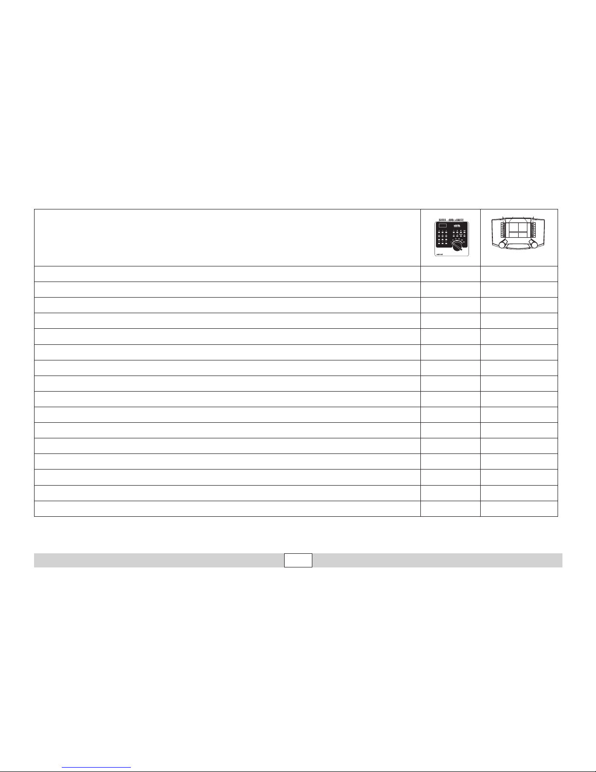
Schakelbare functies
Digital/Systems
Frontsein function/off Functie f0
Rookgenerator (40) f1 Functie f1
Bedrijfsgeluid (40) f2 Functie f2
Geluid & Rook
1
: uit (40) f3 Functie f3
Telex-koppeling (40) f4 Functie f4
Cabineverlichting (41) f1 Functie f5
Drijfwerkverlichting (41) f2 Functie f6
Geluid & Rook: rangeeruit (41) f3 Functie f7
ABV, uit (41) f4 Functie f8
Geluid: piepende remmen uit — Functie f9
Geluid: kolenscheppen — Functie f10
Geluid: kiprooster — Functie f11
Geluid: luchtpomp — Functie f12
Geluid: injector — Functie f13
Geluid: waterpomp — Functie f14
Geluid & Rook
1, 2
: cilinder uitblazen — Functie f15
f0 f8 f0f8
1
alleen in combinatie met F1
2
alleen als de toets langer ingedrukt wordt gehouden.
Page 26

26
Betrieb • Operation • Fonctionnement Exploitatie • Operación • Operazione
CV Betekenis Waarde 6021 Waarde DCC
01 Adres
01 – 80 (40)
1 – 127 (3)
CV 29/Bit 5 =0
02 PoM Minimale snelheid
— 0 – 255 (20)
03 PoM Optrekvertraging
01 – 63 0 – 255 (15)
04 PoM Afremvertraging
01 – 63 0 – 255 (15)
05 PoM Maximumsnelheid
01 – 63 0 – 255 (250)
08 Fabrieksinstelling/fabriekherkenning
08 08 (131)
13 PoM functies F1 - F8 in analoogbedrijf
— 0 – 255 (0)
14 PoM functies F9 - F15 en licht in analoogbedrijf
— 0 – 255 (1)
17 Uitgebreld adres (bovenste gedeelte CV29 Bit 5 = 1)
— 192 – 255 (192)
18 Uitgebreld adres (onderste gedeelte CV29 Bit 5 = 1)
— 0 – 255 (128)
19 tractieadres
— 0 – 255 (0)
21 PoM functies F1 - F8 in tractie
— 0 – 255 (0)
22 PoM functies F9 - F15 en licht in tractie
— 0 – 255 (0)
27 PoM
Bit 4 = normaal afremmen
Bit 5 = tegengesteld afremmen
— 0, 16, 32, 48 (48)
29 PoM
Bit 0: ompolen rijrichting
Bit 1: aantal rijstappen 14 of 28/128
Bit 2: analoogbedrijf aan/uit
Bit 5: adresomvang 7 Bit / 14 Bit
—
0 / 1 (0)*
0 / 2 (2)*
0 / 4 (4)*
0 / 32 (0)*
50 PoM DC Vmax
— 0 – 255 (255)
60 PoM
Multi-stationsomroep
Bit 0 – 3 = aantal stations
Bit 4 = laatste station keert de volgorde om
Bit 5 = loc richting bepaald de volgorde
Bit 6 = volgorde basis instelling
— 0 – 127 (1)
Page 27

27
Betrieb • Operation • Fonctionnement Exploitatie • Operación • Operazione
( ) waarde = fabrieksinstelling
DCC: programmeren op het programmeerspoor door middel van CV programmering,
programmeren met PoM (Program on the Main); dit dient door het besturingsapparaat ondersteund te worden.
* De waarden van de gewenste instellingen dienen bij elkaar opgeteld te worden!
Bijv. aantal rijstappen 28/128 = 2 + DCC bedrijf met afremtraject = 4, geeft een waarde van 2+4=6.
CV Betekenis Waarde 6021 Waarde DCC
63 PoM Volume
01 – 63 (63) 0 – 255 (255)
64 PoM Remdrempel
0 – 255 (255)
75 Adres 2 (1ste vervolgadres)
01 – 80 (41) —
138 PoM Volume Sound „piepende remmen“
— 0 – 255 (255)
139 PoM Volume Sound „bedrijfsgeluid“
— 0 – 255 (255)
140 PoM Volume Sound 1 (fluit)
— 0 – 255 (255)
141 PoM Volume Sound 2 (rangeerfluit)
— 0 – 255 (255)
146 PoM
Volume Sound 7 (waterpomp)
— 0 – 255 (255)
147 PoM
Volume Sound 8 (fluit)
— 0 – 255 (255)
148 PoM
Volume Sound 9 (kolenscheppen)
— 0 – 255 (255)
149 PoM Volume Sound 10 (kiprooster)
— 0 – 255 (255)
150 PoM Volume Sound 11 (luchtpomp)
— 0 – 255 (255)
151 PoM Volume Sound 12 (injector)
— 0 – 255 (255)
152 PoM Volume Sound 13 (cilinder uitblazen)
— 0 – 255 (255)
Page 28

28
Betrieb • Operation • Fonctionnement Exploitatie • Operación • Operazione
Aviso de seguridad
• Está permitido utilizar la locomotora únicamente con un sistema
operativo previsto para la misma (corriente continua [c.c.] = máx.
18V±, Märklin corriente alterna, Märklin Digital o Märklin Systems).
• Emplear únicamente fuentes de alimentación conmutadas y transformadores que sean de la tensión de red local.
• La alimentación de la locomotora deberá realizarse descle una sola
fuente de suminitro.
• Observe bajo todos los conceptos, las medidas de seguridad indicadas en las instrucciones de su sistema de funcionamiento.
• Para el funcionamiento convencional de la locomotora deben suprimirse las interferencias en la vía de conexión de la alimentación.
Para ello debe emplearse el set supresor de interferencias 104770.
El set supresor de interferencias no es adecuado para el funcionamiento en modo digital.
• El cable de conexión a la vía utilizado debe tener una longitud máxima de 2 metros.
• No exponer el modelo en miniatura a la radiación solar directa, a oscilaciones fuertes de temperatura o a una humedad del aire elevada.
• ¡ATENCIÓN! Esquinas y puntas afiladas condicionadas a la función.
• Los LEDs incorporados corresponden a la clase de láser 1 según la
norma europea EN 60825-1.
Notas importantes
•
Debido a la elevada potencia absorbida por esta locomotora, el funcionamiento con la Mobile Station 60652 es posible tan solo de forma limitada.
• Las instrucciones de empleo forman parte íntegra del producto y, por
este motivo, deben conservarse y entregarse al nuevo usuario, si se
transmite el producto a otra persona.
• Para reparaciones o recambios contacte con su proveedor Märklin
especializado.
• Responsabilidad y garantía conforme al documento de garantía que
se adjunta.
• Eliminación: www.maerklin.com/en/imprint.html
Funciones
• El modo de funcionamiento (AC/DC, Mfx, Märklin-Motorola o DCC) se
reconoce automáticamente.
• Tecnología mfx para la Mobile Station/Central Station.
Nombre de fábrica: 41 069
• Códigos disponibles:
1-80 (Control Unit 6021/Mobile Station 60651/652)
1-255 (Central Station 6021x/Mobile Station 60653)
01 – 9999 DCC
• Código de fábrica: (Märklin) 40 & 41 / (DCC) 3
• Conguración de los parámetros de locomotora (dirección, retardo
de arranque/frenado, velocidad máxima, etc): con Control Unit y DCC
(programación de variables CV), Mobile Station o Central Station.
• Si está encendido el humo, pueden activarse funciones de humo
individuales junto con las funciones de ruido (véase página 39).
• En el modo circulación, se posiciona en 5 posiciones, como en el
modelo real, la biela de mando del lado derecho de la locomotora.
• Las puertas de la locomotora y del ténder pueden ser sustituidas por
las puertas adjuntas (pág. 36). Las puertas más grandes pueden dar
lugar a problemas en circulación.
• El modelo en miniatura ha sido desarrollado para el funcionamiento
en vías Märklin 1. El uso en otros sistemas de vías se realiza por
cuenta y riesgo del propio usuario.
• Radio mínimo describible: 1020 mm
• En funcionamiento en modo analógico están disponibles únicamente
las funciones de tracción y de alternancia de luces.
Page 29
29
Betrieb • Operation • Fonctionnement Exploitatie • Operación • Operazione
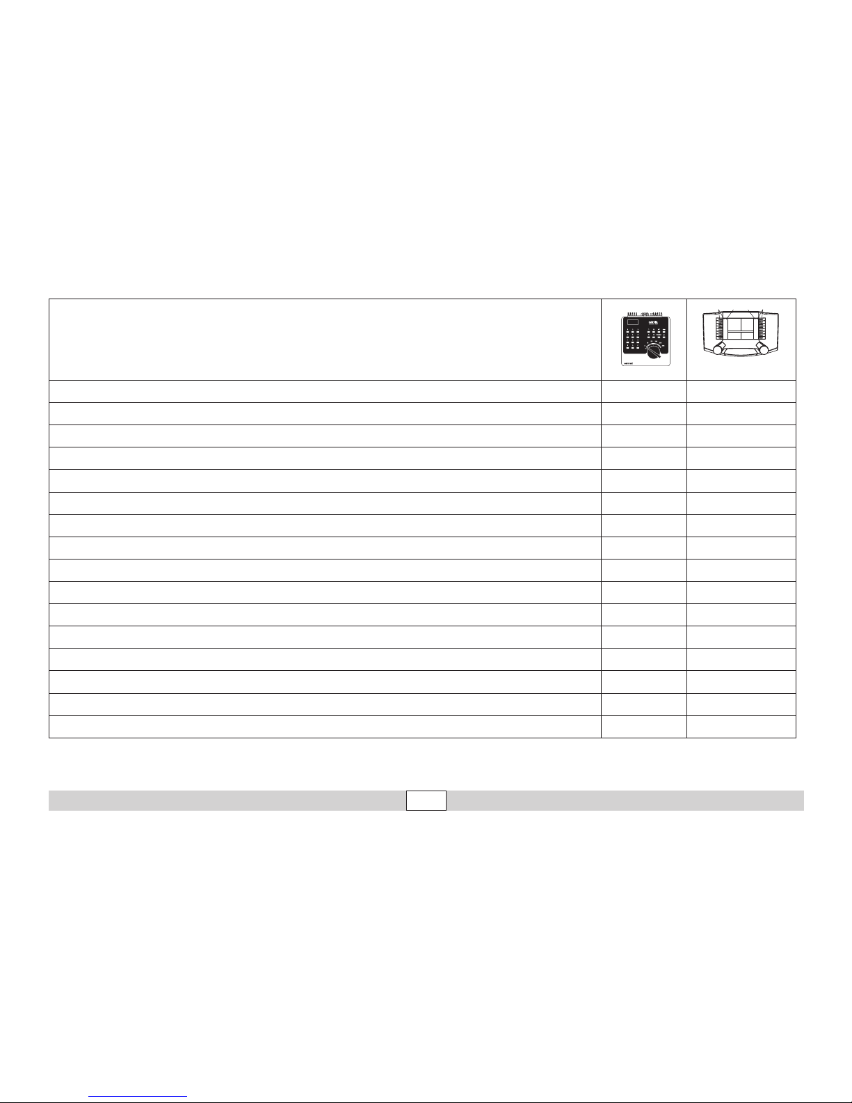
Funciones posibles
Digital/Systems
Faros frontales function/off Función f0
Generador de humo (40) f1 Función f1
Ruido: ruido de explotación (40) f2 Función f2
Ruido & humo
1
: Silbido (40) f3 Función f3
Enganche Telex (40) f4 Función f4
Alumbrado interior de la cabina (41) f1 Función f5
Iluminación de grupo propulsor (41) f2 Función f6
Ruido & humo: Silbato de maniobras (41) f3 Función f7
ABV, apagado (41) f4 Función f8
Ruido: Desconectar chirrido de los frenos — Función f9
Ruido: Cargar carbón con pala — Función f10
Ruido: Parrilla volquete — Función f11
Ruido: Bomba de aire — Función f12
Ruido: Inyector — Función f13
Ruido: Bomba de agua — Función f14
Ruido & humo
1, 2
: Barrido de cilindro — Función f15
f0 f8 f0f8
1
Sólo junto con F1
2
Sólo si se mantiene pulsada la tecla durante un largo tiempo
Page 30

30
Betrieb • Operation • Fonctionnement Exploitatie • Operación • Operazione
CV Significado Valor para 6021 Valor DCC
01 Códigos
01 – 80 (40)
1 – 127 (3)
CV 29/Bit 5 =0
02 PoM Velocidad mínima
— 0 – 255 (20)
03 PoM Arranque progresivo
01 – 63 0 – 255 (15)
04 PoM Frenado progresivo
01 – 63 0 – 255 (15)
05 PoM Velocidad máxima
01 – 63 0 – 255 (250)
08 Reset de fábrica/código de fabricante
08 08 (131)
13 PoM Funciones F1 - F8 en el modo analógico
— 0 – 255 (0)
14 PoM Funciones F9 - F15 y luces en el modo analógico
— 0 – 255 (1)
17 Dirección ampliada (parte superior CV29 Bit 5 =1)
— 192 – 255 (192)
18 Dirección ampliada (parte inferior CV29 Bit 5 =1)
— 0 – 255 (128)
19 Dirección de tracción
— 0 – 255 (0)
21 PoM Funciones F1 - F8 en tracción
— 0 – 255 (0)
22 PoM Funciones F9 - F15 y luces en tracción
— 0 – 255 (0)
27 PoM
Bit 4 = respuesta de frenado normal
Bit 5 = respuesta de frenado inversa
— 0, 16, 32, 48 (48)
29 PoM
Bit 0: Cambio de polaridad del sentido de marcha
Bit 1: número de niveles de marcha 14 ó 28/128
Bit 2: modo analógico
Bit 5: Tamaño de direcciones 7 Bits / 14 Bits
—
0 / 1 (0)*
0 / 2 (2)*
0 / 4 (4)*
0 / 32 (0)*
50 PoM DC Vmax
— 0 – 255 (255)
60 PoM
Locución en múltiples estaciones
Bit 0 – 3 = Número de estaciones
Bit 4 = La última estación invierte el orden de reproducción
Bit 5 = El sentido de la locomotora determina el orden
Bit 6 = Configuración básica de orden de reproducción
— 0 – 127 (1)
Page 31

31
Betrieb • Operation • Fonctionnement Exploitatie • Operación • Operazione
( ) Valores = Configuración de fábrica
DCC: programación en la vía de programación mediante programación de variables CV o
programación con PoM (Program on the Main); la unidad de control debe soportar esta posibilidad.
* ¡Los valores de la configuración deseada deben sumarse!
P. ej. un número de niveles de marcha 28/128 = 2 + funcionamiento en modo DCC con tramo de frenado = 4, arroja un valor de = 6
CV Significado Valor para 6021 Valor DCC
63 PoM Volumen
01 – 63 (63) 0 – 255 (255)
64 PoM Umbral de frenado
0 – 255 (255)
75 Dirección 2 (Primera dirección sucesiva)
01 – 80 (41) —
138 PoM Volumen de sonido "chirrido de frenos"
— 0 – 255 (255)
139 PoM Volumen de sonido "sonido de servicio"
— 0 – 255 (255)
140 PoM Volumen de sonido 1 (Silbato)
— 0 – 255 (255)
141 PoM Volumen de sonido 2 (Silbato de maniobras)
— 0 – 255 (255)
146 PoM
Volumen de sonido 7 (Bomba de agua)
— 0 – 255 (255)
147 PoM
Volumen de sonido 8 (Silbato)
— 0 – 255 (255)
148 PoM
Volumen de sonido 9 (Cargar carbón con pala)
— 0 – 255 (255)
149 PoM Volumen de sonido 10 (Parrilla volquete)
— 0 – 255 (255)
150 PoM Volumen de sonido 11 (Bomba de aire)
— 0 – 255 (255)
151 PoM Volumen de sonido 12 (Inyector)
— 0 – 255 (255)
152 PoM Volumen de sonido 13 (Barrido de cilindro)
— 0 – 255 (255)
Page 32

32
Betrieb • Operation • Fonctionnement Exploitatie • Operación • Operazione
Avvertenze per la sicurezza
• Tale locomotiva deve venire impiegata soltanto con un sistema di
esercizio adeguato a tale scopo (corrente continua [DC] = max 18V±,
Märklin a corrente alternata, Märklin Digital oppure Märklin Systems).
• Impiegare soltanto alimentatori “switching“ e trasformatori che
corrispondono alla Vostra tensione di rete locale.
• La locomotiva non deve venire alimentata nello stesso tempo con più
di una sorgente di potenza.
• Vogliate prestare assolutamente attenzione alle avvertenze di sicurezza nelle istruzioni di impiego per il Vostro sistema di funzionamento.
• Per il funzionamento tradizionale della locomotiva il binario di alimentazione deve essere protetto dai disturbi. A tale scopo si deve impiegare il
corredo antidisturbi 104770. Tale corredo antidisturbi non è adatto per il
funzionamento Digital.
• Il cavo di collegamento al binario impiegato deve essere lungo al
massimo soltanto 2 metri.
• Non esponete tale modello ad alcun irraggiamento solare diretto, a forti
escursioni di temperatura oppure a elevata umidità dell’aria.
• AVVERTENZA! Per motivi funzionali i bordi e le punte sono spigolosi.
• I LED incorporati corrispondono alla categoria di laser 1 secondo la
Norma EN 60825-1.
Avvertenze importanti
• A causa dell’elevato assorbimento di potenza di questa locomotiva
il funzionamento con la Mobile Station 60652 è possibile soltanto
limitatamente.
• Le istruzioni di impiego costituiscono parte integrante del prodotto e
devono pertanto venire conservate, nonché consegnate insieme in
caso di cessione del prodotto ad altri.
•
Per le riparazioni o le parti di ricambio, contrattare il rivenditore Märklin.
• Prestazioni di garanzia e garanzia in conformità all’accluso certicato di garanzia.
• Smaltimento: www.maerklin.com/en/imprint.html
Funzioni
•
Il tipo di funzionamento (AC/DC, Mfx, Märklin-Motorola oppure DCC)
viene riconosciuto automaticamente.
• Tecnologia Mfx per Mobile Station / Central Station.
Nome di fabbrica: 41 069
• Einstellbare Adressen:
1-80 (Control Unit 6021/Mobile Station 60651/652)
1-255 (Central Station 6021x/Mobile Station 60653)
01 – 9999 DCC
• Adresse ab Werk: (Märklin) 40 & 41 / (DCC) 3
• Impostazione dei parametri della locomotiva (indirizzo, ritardi di avviamento/frenatura, velocità massima ecc.): con Control Unit e DCC
(programmazione CV), Mobile Station oppure Central Station.
• In caso di fumo attivato, le singole funzionalità fumogene sono
comandabili insieme con le funzioni sonore (si veda a pagina 39).
• Nell’esercizio di marcia l’asta della distribuzione sul lato destro della
locomotiva viene spostata tramite un motore in 5 posizioni fedelmente al prototipo.
• Le porte sulla locomotiva e sul tender possono venire sostituite
mediante le porte accluse (pag. 36). A causa di quelle più grandi
possono verificarsi dei problemi nell’esercizio di marcia.
• Tale modello è sviluppato per l’esercizio su binari Märklin 1. Un
esercizio su altri sistemi di binario avviene a proprio rischio.
• Raggio minimo percorribile: 1020 mm
• Nel funzionamento analogico si hanno a disposizione solamente le
funzioni di marcia e di commutazione dei fanali.
Page 33
33
Betrieb • Operation • Fonctionnement Exploitatie • Operación • Operazione
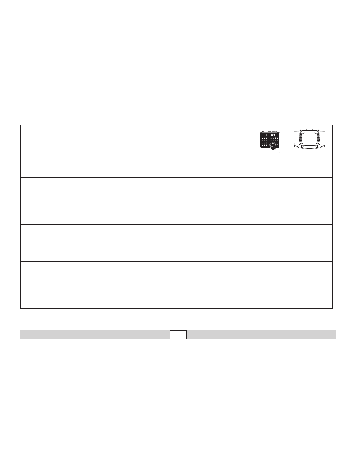
Funzioni commutabili
Digital/Systems
Illuminazione di testa function/off Funzione f0
Apparato fumogeno (40) f1 Funzione f1
Rumore: rumori di esercizio (40) f2 Funzione f2
Rumore & vapore
1
: Fischio (40) f3 Funzione f3
Gancio Telex (40) f4 Funzione f4
Illuminazione della cabina (41) f1 Funzione f5
Illuminazione del rodiggio (41) f2 Funzione f6
Rumore & vapore: schio di manovra (41) f3 Funzione f7
ABV, spento (41) f4 Funzione f8
Rumore: stridore dei freni escluso — Funzione f9
Rumore: Spalatura del carbone — Funzione f10
Rumore: Griglia ribaltabile — Funzione f11
Rumore: compressore dell’aria — Funzione f12
Rumore: iniettore — Funzione f13
Rumore: pompa di alimentazione acqua — Funzione f14
Rumore & vapore
1, 2
: sbuf dai cilindri — Funzione f15
f0 f8 f0f8
1
soltanto in abbinamento con F1
2
soltanto quando il tasto rimane premuto più a lungo
Page 34

34
Betrieb • Operation • Fonctionnement Exploitatie • Operación • Operazione
CV Significato Valore per 6021 Valore DCC
01 Indirizzo
01 – 80 (40)
1 – 127 (3)
CV 29/Bit 5 =0
02 PoM Velocità minima
— 0 – 255 (20)
03 PoM Ritardo di avviamento
01 – 63 0 – 255 (15)
04 PoM Ritardo di frenatura
01 – 63 0 – 255 (15)
05 PoM Velocità massima
01 – 63 0 – 255 (250)
08 Ripristino di fabbrica/Identificazione di produzione
08 08 (131)
13 PoM Funzioni F1 - F8 in esercizio analogico
— 0 – 255 (0)
14 PoM Funzioni F9 - F15 e luci in esercizio analogico
— 0 – 255 (1)
17 Indirizzo ampliato (parte superiore CV29 Bit 5 =1)
— 192 – 255 (192)
18 Indirizzo ampliato (parte inferiore CV29 Bit 5 =1)
— 0 – 255 (128)
19 Indirizzo di trazione
— 0 – 255 (0)
21 PoM Funzioni F1 - F8 durante trazione
— 0 – 255 (0)
22 PoM Funzioni F9 - F15 e luci durante trazione
— 0 – 255 (0)
27 PoM
Bit 4 = comportam. frenatura normale
Bit 5 = comportam. frenatura inverso
— 0, 16, 32, 48 (48)
29 PoM
Bit 0: Scambio poli senso di marcia
Bit 1: Numero gradazioni di marcia 14 o 28/128
Bit 2: esercizio analogico attivi/spenti
Bit 5: Ampiezza indirizzo 7 Bit / 14 Bit
—
0 / 1 (0)*
0 / 2 (2)*
0 / 4 (4)*
0 / 32 (0)*
50 PoM DC Vmax
— 0 – 255 (255)
60 PoM
Annuncio di stazione multiplo
Bit 0 – 3 = numero delle stazioni
Bit 4 = l’ultima stazione fa invertire la sequenza
Bit 5 = la direzione della locomotiva determina la sequenza
Bit 6 = impostazione di base della sequenza
— 0 – 127 (1)
Page 35

35
Betrieb auf der Anlage • Operation on a layout • Exploitation sur réseau
Bedrijf op een modelbaan • Funcionamiento del sistema • Funzionamento del sistema
( ) Valore = impostazione di fabbrica
DCC: programmazione sul binario di programmazione per mezzo della programmazione CV,
programmazione con PoM (Program on the Main); questo deve essere supportato dall’apparato di comando.
* I valori delle impostazioni desiderate si devono addizionare!
Ad es. numero delle gradazioni di marcia 28/128 = 2 + esercizio DCC con tratta di frenatura = 4, determina un valore = 6
CV Significato Valore per 6021 Valore DCC
63 PoM Intensità sonora
01 – 63 (63) 0 – 255 (255)
64 PoM Soglia di frenatura
0 – 255 (255)
75 Indirizzo 2 (1° indirizzo concatenato)
01 – 80 (41) —
138 PoM Intensità effetto sonoro „stridore dei freni“
— 0 – 255 (255)
139 PoM Intensità effetto sonoro „rumori di esercizio“
— 0 – 255 (255)
140 PoM Intensità effetto sonoro 1 (fischio)
— 0 – 255 (255)
141 PoM Intensità effetto sonoro 2 (fischio di manovra)
— 0 – 255 (255)
146 PoM
Intensità effetto sonoro 7 (pompa di alimentazione acqua)
— 0 – 255 (255)
147 PoM
Intensità effetto sonoro 8 (fischio)
— 0 – 255 (255)
148 PoM
Intensità effetto sonoro 9 (Spalatura del carbone)
— 0 – 255 (255)
149 PoM Intensità effetto sonoro 10 (Griglia ribaltabile)
— 0 – 255 (255)
150 PoM Intensità effetto sonoro 11 (compressore dell’aria)
— 0 – 255 (255)
151 PoM Intensità effetto sonoro 12 (iniettore)
— 0 – 255 (255)
152 PoM Intensità effetto sonoro 13 (sbuffi dai cilindri)
— 0 – 255 (255)
Page 36
36
Betrieb auf der Anlage • Operation on a layout • Exploitation sur réseau
Bedrijf op een modelbaan • Funcionamiento del sistema • Funzionamento del sistema
!
Page 37
37
Betrieb auf der Anlage • Operation on a layout • Exploitation sur réseau
Bedrijf op een modelbaan • Funcionamiento del sistema • Funzionamento del sistema
1
2
3
Page 38
38
Betrieb auf der Anlage • Operation on a layout • Exploitation sur réseau
Bedrijf op een modelbaan • Funcionamiento del sistema • Funzionamento del sistema
02421
< 8 ml
1
2
r > 2300 mm
Page 39
39
Betrieb auf der Anlage • Operation on a layout • Exploitation sur réseau
Bedrijf op een modelbaan • Funcionamiento del sistema • Funzionamento del sistema
CV 263 + CV 363
Sound 4
128 / 0
CV 264 + CV 364
Sound 8
8 / 0
CV 265 + CV 365
Sound 15
4 / 0
SMOKE
ON OFF
Page 40

40
Betrieb auf der Anlage • Operation on a layout • Exploitation sur réseau
Bedrijf op een modelbaan • Funcionamiento del sistema • Funzionamento del sistema
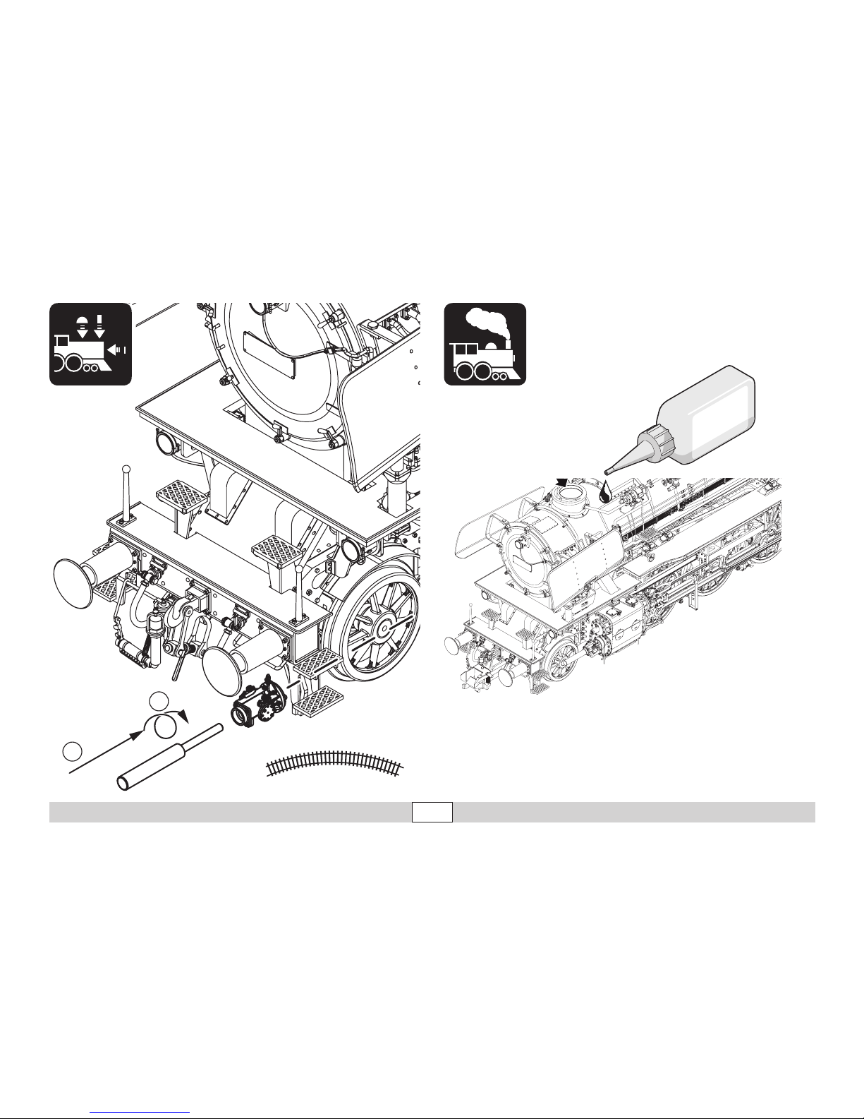
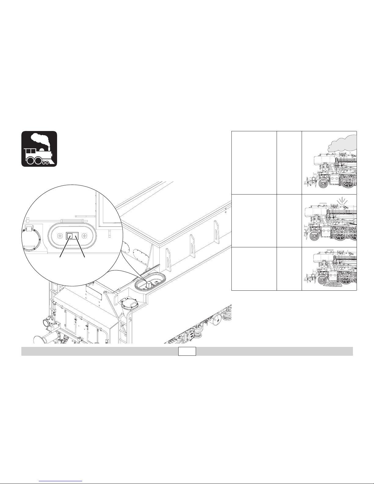
Der eingebaute Dampfentwickler erzeugt den
Dampf für den Schornstein, Pfeife, sowie für
die radsynchronen Zylinderschläge.
Bei stehender Lok oder im Leerlauf schaltet
der Dampfentwickler nach max. 5 min. automatisch ab (schaltet durch Anfahren der Lok
wieder ein).
Füllen Sie den Dampfgenerator erst dann
auf, wenn die Lok auf dem Gleis steht. Der
Dampfgenerator darf mit max. 8 ml. Dampföl
02421befüllt werden; anschließend 2 min.
vorheizen. Wird die Lok mit gefülltem Dampfgenerator gekippt, so läuft das Dampföl über
einen Überlauf durch die Zylinder wieder aus.
Der Zylinder-Dampfausstoß wird dadurch
zunächst gestört.
Da alle 3 Dampffunktionalitäten auf einer
Funktion zusammengefasst sind, können sie
auch nur zusammen über die Funktiostaste
am Fahrgerät geschaltet werden. Zusätzlich
ist im Tender ein Schalter (siehe Seite 39),
mit dem der Dampf komplett ausgeschaltet
werden kann.
Sollen einzelne Dampffunktionalitäten ausgeschaltet werden, so ist das nur über das
Funkionsmapping am Steuergerät (mfx) oder
über die CV-Programmierung (DCC) möglich
(siehe Seite 39).
Le générateur intégré génère la fumée pour la
cheminée, le sifflet, ainsi que pour les coups
d’échappements synchrones avec le mouvement des roues.
Lorsque la locomotive est arrêtée ou qu‘elle
roule sur son erre, le générateur de fumée
s’éteint automatiquement au bout de 5 minutes maximum (et se rallume au démarrage
de la locomotive).
Ne remplissez le générateur de fumée que
lorsque la locomotive est sur la voie. Le générateur de fumée ne peut contenir que 8 ml
d’huile fumigène réf 02421 max. ; comptez
ensuite 2 minutes de préchauffage. Si la
locomotive est renversée avec le générateur
plein, l’huile s’écoule par un déversoir via
les cylindres. Le coup d’échappement des
cylindres s’en trouve d’abord perturbé.
Les 3 fonctionnalités relatives à la vapeur
étant regroupées sous une seule fonction, elles ne peuvent être déclenchées qu’ensemble
via la touche de fonction située sur le
régulateur de marche. Un autre interrupteur
situé dans le tender (voir page 39) permet de
désactiver complètement la génération de la
fumée.
Pour désactiver individuellement certaines
fonctionnalités vapeur, il est donc nécessaire
de passer par le mapping des fonctions sur
l‘appareil de commande (mfx) ou par la programmation des CV (DCC) (voir page 39).
The built-in smoke generator produces smoke
and steam for the smoke stack, whistle, and
for the cylinder strokes synchronized to the
wheels.
When the locomotive is standing at a halt or
is running „light“ the smoke generator will
shut off automatically after a maximum of 5
minutes (it comes back on when the locomotive starts to accelerate).
Do not fill the smoke generator until it is
standing on the track. The smoke generator
may be filled with a maximum of 8 milliliters
/ 0.27 fluid ounces of 02421 smoke fluid; then
pre-heat it for 2 minutes. If the locomotive
with a full smoke generator is tipped over,
the smoke fluid will run out by means of an
overflow through the cylinders. The cylinder
steam exhaust will be interrupted by this.
Since all 3 steam and smoke functions are
combined into one function, they can also
be activated only together by means of the
function button on the locomotive controller.
In addition, there is a switch in the tender (see
page 39) with which the steam and smoke can
be turned off completely.
If you want to control individual steam and
smoke functions, then that is only possible
with the function mapping on the controller
(mfx) or by means of CV programming (DCC)
(see page 39).
Page 41

41
Betrieb auf der Anlage • Operation on a layout • Exploitation sur réseau
Bedrijf op een modelbaan • Funcionamiento del sistema • Funzionamento del sistema
De ingebouwde dampgenerator maakt damp
voor de schoorsteen, fluit en eveneens voor
de wielas synchrone cilinderslagen.
Bij stilstaande loc of in leegloop schakelt de
dampgenerator na max. 5 minuten automatisch uit (schakelt door te gaan rijden met de
loc weer in).
Vul de dampgenerator pas als de loc op de
rails staat. De dampgenerator mag met max.
8 ml. dampvloeistof 02421 gevuld worden;
aansluitend 2 min. Voorverwarmen. Als de loc
met een gevulde dampgenerator omgekipt
wordt, loopt de dampvloeistof via een overloop in de cilinders er weer uit. De cilinder
stoomuitstoot wordt daardoor vervolgens
verstoort.
Aangezien alle 3 dampfuncties in één functie
samengevat zijn, kunnen ze ook alleen gezamenlijk via de functietoets op de rijregelaar
geschakeld worden. In de tender is een
extra schakelaar aangebracht (zie pag. 39),
waarmee de damp geheel uitgeschakeld kan
worden.
Moet één van de dampfuncties uitgeschakeld
worden, dan is dat via de functie-mapping op
de rijregelaar (mfx) of via de CV programmering (DCC) mogelijk (zie pag. 39).
El generador de vapor incorporado genera el
vapor para la chimenea, el silbato así como
los golpes de los cilindros en sincronismo con
las ruedas.
Cuando la locomotora está en reposo o en
ralentí, el generador de vapor se apaga automáticamente al cabo de como máx. 5 min.
(y vuelve a arrancar cuando la locomotora
reanuda la marcha).
No rellene el generador de vapor hasta que la
locomotora esté sobre la vía. Está permitido
llenar el generador con como máx. 8 ml. de
aceite de vapor 02421; a continuación, precalentar 2 min. Si se vuelca la locomotora con el
generador de vapor lleno, el aceite de vapor
vuelve a salir a través de los cilindros mediante un rebosadero. En principio, esto perturba
la expulsión del vapor de los cilindros.
Dado que las 3 funcionalidades de vapor
están concentradas en una sola función,
pueden conmutarse también solo juntas
mediante la tecla de función de la unidad de
conducción. Además, el ténder incorpora un
interruptor (véase página 39) con el cual se
puede desconectar totalmente el vapor.
Si se desea desconectar algunas funcionalidades de vapor concretas, esto es posible
únicamente mediante el mapeado de funciones de la unidad de control (mfx) o mediante la programación de variables CV (DCC)
(véase página 39).
Il generatore di vapore incorporato produce il
vapore per il fumaiolo, il fischio, nonché per i
colpi di scappamento dei cilindri sincronizzati
con le ruote.
In caso di locomotiva in sosta oppure nella
circolazione a vuoto, il generatore di vapore si
disattiva automaticamente dopo un max. di 5
minuti (si riattiva nuovamente in seguito all’avvio
della locomotiva).
Vogliate riempire il generatore di vapore soltanto
allorché la locomotiva si trova sul binario. Il generatore di vapore deve venire riempito al max. con
8 ml di olio vaporizzabile 02421; successivamente,
preriscaldare per 2 min. Qualora la locomotiva
con il generatore di vapore riempito venga
rovesciata, l’olio vaporizzabile defluisce allora
di nuovo attraverso i cilindri a causa di un flusso
eccessivo. Lo scappamento del vapore dai cilindri
viene in tal modo inizialmente disturbato.
Poiché tutte le 3 funzionalità di vaporizzazione
sono riunite assieme in una sola funzione, anche
sul regolatore di marcia esse possono venire
commutate soltanto assieme tramite il tasto di
funzione. In aggiunta, nel tender vi è un commutatore (si veda a pagina 39) con il quale il vapore
può venire completamente disattivato.
Qualora debbano venire disattivate delle funzionalità del vapore singole, questo è possibile allora soltanto tramite la mappatura delle funzioni
sull’apparato di comando (mfx) oppure mediante
la programmazione delle CV (DCC)
(si veda a pagina 39).
Page 42
42
Wartung • Maintenance • Entretien Onderhoud • Mantenimiento • Manutenzione
40h
Page 43
43
40h
Page 44
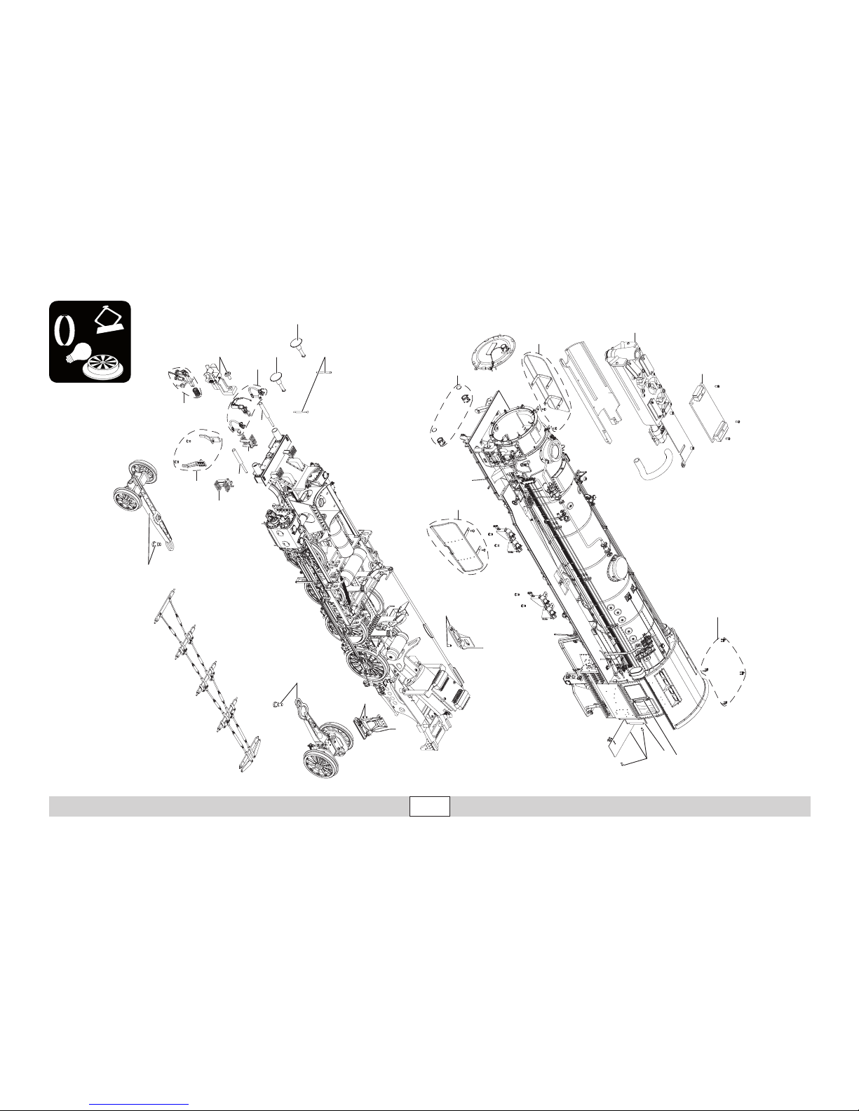
44
Ersatzteile • Spare Parts • Pièces de rechange
Onderdelen •
Recambios • Pezzi di ricambio
1
10
22
22
12
13
5
6
7
4
9
11
14
15
16
23
17
3
21
21
18
8
19/20
2
Details der Darstel-
lung können von dem
Modell abweichen.
Page 45

45
Ersatzteile • Spare Parts • Pièces de rechange
Onderdelen •
Recambios • Pezzi di ricambio
1 Kranhaken E272 704
2 Windabweiser E272 705
3 Windleitblech links E272 707
4 Windleitblech rechts E272 708
5 Rauchsatzcontroller E262 128
6 Rauchsatz E272 706
7 Lampengehäuse vorn E272 775
8 Indusi rechts E272 777
9 Indusi links —
10 Vorläufer E272 796
11 Nachläufer E272 797
12 Schieneräumer E272 855
13 Schraubenkupplung E259 976
14 Klauenkupplung E259 977
15 Puffer rund E272 854
16 Puffer flach E272 853
17 Rangiergriffe E272 856
18 Übergangsblech E272 857
19 Türen schmal E272 858
20 Türen breit E272 859
21 Rangiertritte E272 861
22 Kolbenstangenschutzrohre E272 862
23 Bremsschläuche Lok E272 863
24 Leitern E272 867
25 Lampen E272 776
26 Schraube (Lautsprecher) E270 194
27 Schraube (Resonator) E272 872
28 Bremsschläuche Tender E272 864
29 Tritte E272 865
30 Lagerbolzen E272 866
31 Druckfeder E272 868
32 Tenderdrehgestell vorne E272 869
33 Tenderdrehgestell hinten E272 871
34 Leiterplatte E262 119
35 Decoder 262 132
36 Lautsprecher E266 663
Verbindungskabel Lok-Tender E269 215
Hinweis: Einige Teile werden nur ohne oder mit
anderer Farbgebung angeboten.
Teile, die hier nicht aufgeführt sind, können nur
im Rahmen einer Reparatur im Märklin-Repara-
tur-Service repariert werden.
Page 46
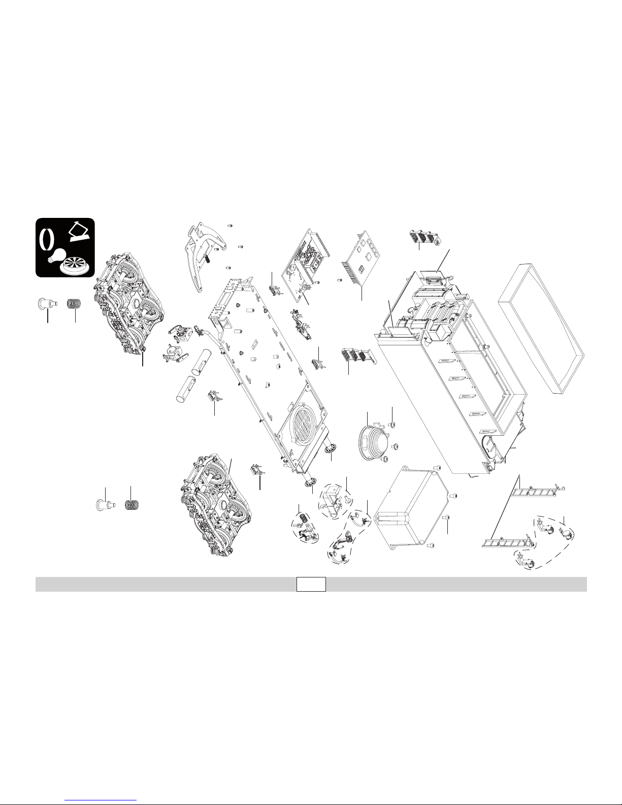
46
Ersatzteile • Spare Parts • Pièces de rechange
Onderdelen •
Recambios • Pezzi di ricambio
16
15
23
35
34
24
27
29
29
31
32
30
29
29
28
15
36
13
26
19/20
19/20
25
24
31
33
30
Details der Darstel-
lung können von dem
Modell abweichen.
Page 47

47
Ersatzteile • Spare Parts • Pièces de rechange
Onderdelen •
Recambios • Pezzi di ricambio
Page 48

Gebr. Märklin & Cie. GmbH
Stuttgarter Str. 55 - 57
73033 Göppingen
Germany
www.maerklin.com
263821/0416/Sm2Ef
Änderungen vorbehalten
© Gebr. Märklin & Cie. GmbH
Due to different legal requirements regarding electro-magnetic compatibility,
this item may be used in the USA only after separate certification for FCC compliance and an adjustment if necessary.
Use in the USA without this certification is not permitted and absolves us of any
liability. If you should want such certification to be done, please contact us –
also due to the additional costs incurred for this.
www.maerklin.com/en/imprint.html
 Loading...