

Page 1
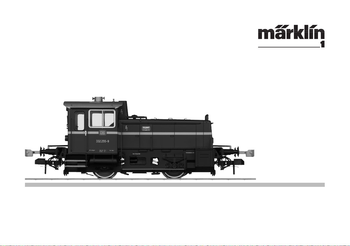
Modell der Diesellokomotive Köf III
55332
Page 2

2
Inhaltsverzeichnis: Seite
Sicherheitshinweise 3
Allgemeine Hinweise 3
Funktionen 3
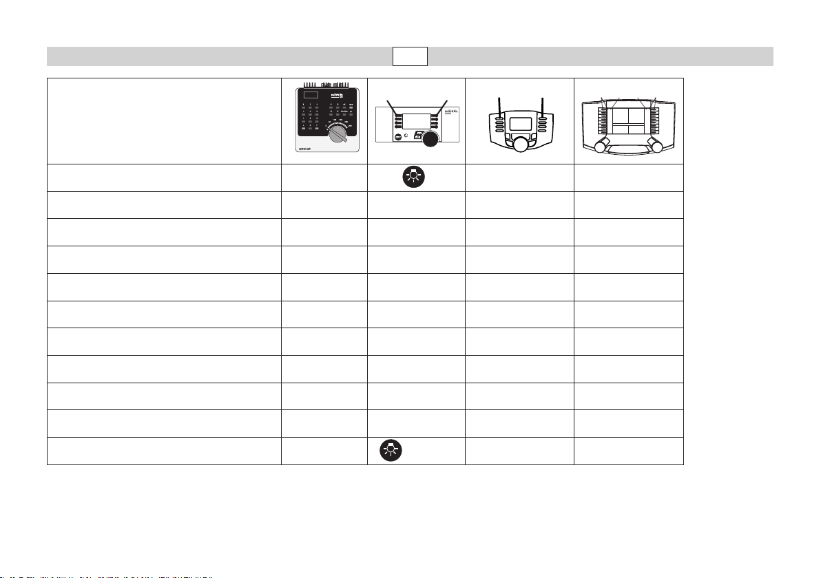
Schaltbare Funktionen 4
CV / Parameter 5
Betriebshinweise 15
Wartung und Instandhaltung 17
Table of Contents: Page
Safety Notes 6
General Notes 6
Functions 6
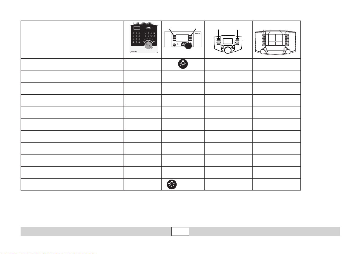
Controllable Functions 7
CV / Parameter 8
Information about operation 15
Service and maintenance 17
Sommaire : Page
Remarques importantes sur la sécurité 9
Informations générales 9
Fonctionnement 9
Fonctions commutables 10
CV / Paramètre 11
Remarques sur l’exploitation 15
Entretien et maintien 17
Inhoudsopgave: Pagina
Veiligheidsvoorschriften 12
Algemene informatie 12
Functies 12
Schakelbare functies 13
CV / Parameter 14
Opmerkingen over de werking 15
Onderhoud en handhaving 17
Page 3

Sicherheitshinweise
• Die Lok darf nur mit einem dafür bestimmten Betriebssystem (Gleichstrom [DC] = max 18V±, Märklin Wechselstrom, Märklin Digital, DCC
oder Märklin Systems) eingesetzt werden.
• Nur Schaltnetzteile und Transformatoren verwenden, die Ihrer örtlichen Netzspannung entsprechen.
• Die Lok darf nur aus einer Leistungsquelle gleichzeitig versorgt wer-
den.
• Beachten Sie unbedingt die Sicherheitshinweise in der Bedienungsanleitung zu Ihrem Betriebssystem.
• Für den konventionellen Betrieb der Lok muss das Anschlussgleis
entstört werden. Dazu ist das Entstörset 104 770 zu verwenden. Für
Digitalbetrieb ist das Entstörset nicht geeignet.
• Das verwendete Gleisanschlusskabel darf maximal 2 Meter lang sein.
• ACHTUNG! Funktionsbedingte scharfe Kanten und Spitzen.
Allgemeine Hinweise
• Die Bedienungsanleitung ist Bestandteil des Produktes und muss
deshalb aufbewahrt sowie bei Weitergabe des Produktes mitgegeben werden.
• Für Reparaturen oder Ersatzteile wenden Sie sich bitte an Ihren
Märklin-Fachhändler.
• http://www.maerklin.com/en/imprint.html
Jegliche Garantie-, Gewährleistungs- und Schadensersatzansprüche sind ausgeschlossen,
wenn in Märklin-Produkten nicht von Märklin freigegebene Fremdteile eingebaut werden
und / oder Märklin-Produkte umgebaut werden und die eingebauten Fremdteile bzw. der
Umbau für sodann aufgetretene Mängel und / oder Schäden ursächlich war. Die Darlegungs- und Beweislast dafür, dass der Einbau von Fremdteilen oder der Umbau in bzw. von
Märklin-Produkten für aufgetretene Mängel und / oder Schäden nicht ursächlich war, trägt
die für den Ein- und / oder Umbau verantwortliche Person und / oder Firma bzw. der Kunde.
Funktionen
•
Die Betriebsart (Mfx, Märklin-Motorola oder DCC) wird automatisch
erkannt.
• Einstellbare Adressen:
Märklin 01 – 255 / Control Unit 1 – 80, DCC 01 - 9999
• Adresse ab Werk: (Märklin) 32 / (DCC) 03
• Mfx-Technologie für Mobile Station / Central Station.
Name ab Werk: BR 332 255-9
• Veränderbare Anfahrverzögerung (ABV).
• Veränderbare Bremsverzögerung (ABV).
• Veränderbare Höchstgeschwindigkeit.
• Veränderbare Lautstärke der Geräusche.
• Einstellen der Lokparameter (Adresse, Anfahr-/Bremsverzögerung,
Höchstgeschwindigkeit usw.): mit Control Unit und DCC (CV Program-
mierung), Mobile Station oder Central Station.
• Eingebaute Geräuschelektronik, nur im Betrieb mit Märklin Digital,
Märklin Systems oder DCC nutzbar.
• Das Modell ist für den Betrieb auf Märklin 1-Gleisen entwickelt. Ein
Betrieb auf anderen Gleissystemen geschieht auf eigenes Risiko.
• Befahrbarer Mindestradius: 1.020 mm
• Im Analogbetrieb stehen nur die Fahr- und Lichtwechselfunktionen
zur Verfügung.
• Hinweis für den Betrieb mit der Mobile Station:
Bei dauerhaft sehr hohem Leistungsbedarf schaltet die Mobile Station
wie bei einem Kurzschluss komplett ab. Verringern Sie in diesem Fall
die Anzahl der Funktionen und schalten Sie das System anschließend
durch Drücken auf die STOP-Taste wieder ein.
3
Page 4
4
f0 - f3 f4 - f7
1
5
systems
f0 f8 f0f8
Schaltbare Funktionen
STOP
mobile station
Stirnbeleuchtung function/off Funktion f0 Funktion f0
Telexkupplung vorn f1 Funktion 6 Funktion f1 Funktion f1
Betriebsgeräusch f2 Funktion 2 Funktion f2 Funktion f2
Geräusch: Horn f3 Funktion 5 Funktion f3 Funktion f3
Telexkupplung hinten f4 Funktion 3 Funktion f4 Funktion f4
Geräusch: Bremsenquietschen aus — Funktion 7 Funktion f5 Funktion f5
Licht hinten aus — Funktion 1 Funktion f6 Funktion f6
Licht vorne aus — Funktion 8 Funktion f7 Funktion f7
ABV — Funktion 4 Funktion f8 Funktion f8
Kuppelgeräusch — — Funktion f9 Funktion f9
Rangierlicht doppel A — + 1 + 8 f0 + f6 + f7 f0 + f6 + f7
Page 5
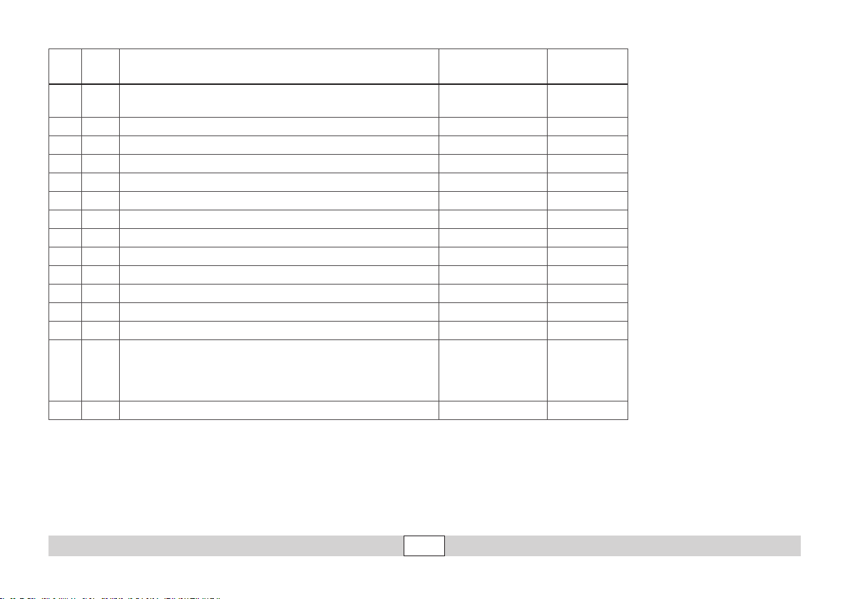
CV Bedeutung Wert für 6021 Wert DCC
01 Adresse 01 - 80
02 PoM Minimalgeschwindigkeit — 0 - 255 (25)
03 PoM Anfahrverzögerung 01 - 63 0 - 255 (15)
04 PoM Bremsverzögerung 01 - 63 0 - 255 (15)
05 PoM Maximalgeschwindigkeit 01 - 63 0 - 255 (255)
08 Werkreset/Herstellerkennung 08 08 (131)
13 PoM Funktionen F1 - F8 im Analogbetrieb — 0 - 255 (0)
14 PoM Funktionen F9 - F15 und Licht im Analogbetrieb — 0 - 255 (1)
17 Erweiterte Adresse (oberer Teil CV29 Bit 5 =1) — 193 - 255 (192)
18 Erweiterte Adresse (unterer Teil CV29 Bit 5 =1) — 0 - 255 (128)
19 Traktionsadresse — 0 - 255 (0)
21 PoM Funktionen F1 - F8 bei Traktion — 0 - 255 (6)
22 PoM Funktionen F9 - F15 und Licht bei Traktion — 0 - 255 (0)
Bit 0: Umpolung Fahrtrichtung
29
63 Lautstärke 01 - 63 0 - 255 (255)
( ) Werte = Werkseinstellung
DCC: programmieren auf dem Programmiergleis mittels CV Programmierung, programmieren mit PoM (Program on the Main);
dies muss vom Steuergerät unterstützt werden.
* Die Werte der gewünschten Einstellungen sind zu addieren!
Z.B. Anzahl der Fahrstufen 28/128 = 2 + DCC Betrieb mit Bremsstrecke = 4, ergibt Wert = 6
Bit 1: Anzahl Fahrstufen 14 oder 28/128
Bit 2: DCC Betrieb mit Bremsstrecke
Bit 5: Adressumfang 7 Bit / 14 Bit
—
1 - 127 (03)
CV 29/Bit5 =0
0 / 1 (0)*
0 / 2 (2)*
0 / 4 (4)*
0 / 32 (0)*
5
Page 6

6
Safety Notes
• This locomotive is to be used only with an operating system designed
for it (DC power = 18V±, Märklin AC, Märklin Digital, Märklin Systems,
DCC).
• Use only switched mode power supply units and transformers that
are designed for your local power system.
• This locomotive must never be supplied with power from more than
one transformer.
• Pay close attention to the safety notes in the instructions for your
operating system.
• The feeder track must be equipped to prevent interference with
radio and television reception, when the locomotive is to be run in
conventional operation. The 104 770 interference suppression set is
to be used for this purpose.
• The wire used for feeder connections to the track may only be a
maximum of 2 meters / 39 inches long.
• WARNING! Sharp edges and points required for operation.
General Notes
• The operating instructions are a component part of the product and
must therefore be kept as well as transferred along with the product
to others.
• Please see your authorized Märklin dealer for repairs or spare parts.
• http://www.maerklin.com/en/imprint.html
No warranty or damage claims shall be accepted in those cases where parts neither manufactured nor approved by Märklin have been installed in Märklin products or where Märklin
products have been converted in such a way that the non-Märklin parts or the conversion
were causal to the defects and / or damage arising. The burden of presenting evidence and
the burden of proof thereof, that the installation of non-Märklin parts or the conversion in
or of Märklin products was not causal to the defects and / or damage arising, is borne by
the person and / or company responsible for the installation and / or conversion, or by the
customer.
Functions
• The mode of operation (mfx, Märklin Motorola, or DCC) is recognized
automatically.
• Possible addresses:
Märklin 01 – 255 / Control Unit 1 – 80, DCC 01 - 9999
• Address set at the factory: (Märklin) 32 / (DCC) 03
• Mfx technology for the Mobile Station / Central Station.
Name set at factory: BR 332 255-9
• Adjustable acceleration (ABV).
• Adjustable Braking delay (ABV)
• Adjustable maximum speed.
• Volume can be changed for the sound effects.
• Setting locomotive parameters (address, acceleration/braking delay,
maximum speed, etc.): with the Control Unit and DCC (CV program-
ming), Mobile Station, or the Central Station.
• Built-in sound effects circuit, can only be used in operation
Märklin Digital, Märklin Systems, or DCC.
• The model is designed for operation on Märklin 1 Gauge track. As the
consumer you assume the risk for operating on other makes of track.
• Minimum radius for operation: 1020 mm / 40-1/6“.
• Only the train control functions and headlight changeover feature are
available in analog operation.
• Note for operation with the Mobile Station:
When there is a continued very high power consumption, the Mobile
Station shuts off completely like a short circuit. In this situation, reduce the number of functions and then turn the system on by pressing
the STOP button again.
Page 7
f0 - f3 f4 - f7
Controllable Functions
1
STOP
mobile station
5
systems
f0 f8 f0f8
Headlights function/off Function f0 Function f0
Front Telex coupler f1 Function 6 Function f1 Function f1
Operating sounds f2 Function 2 Function f2 Function f2
Sound effect: Horn f3 Function 5 Function f3 Function f3
Rear Telex coupler f4 Function 3 Function f4 Function f4
Sound effect: Squealing brakes off — Function 7 Function f5 Function f5
Rear Headlights off — Function 1 Function f6 Function f6
Front Headlights off — Function 8 Function f7 Function f7
ABV — Function 4 Function f8 Function f8
Sound effect: Sounds of couplers — — Function f9 Function f9
Double A switching light — + 1 + 8 f0 + f6 + f7 f0 + f6 + f7
7
Page 8
8
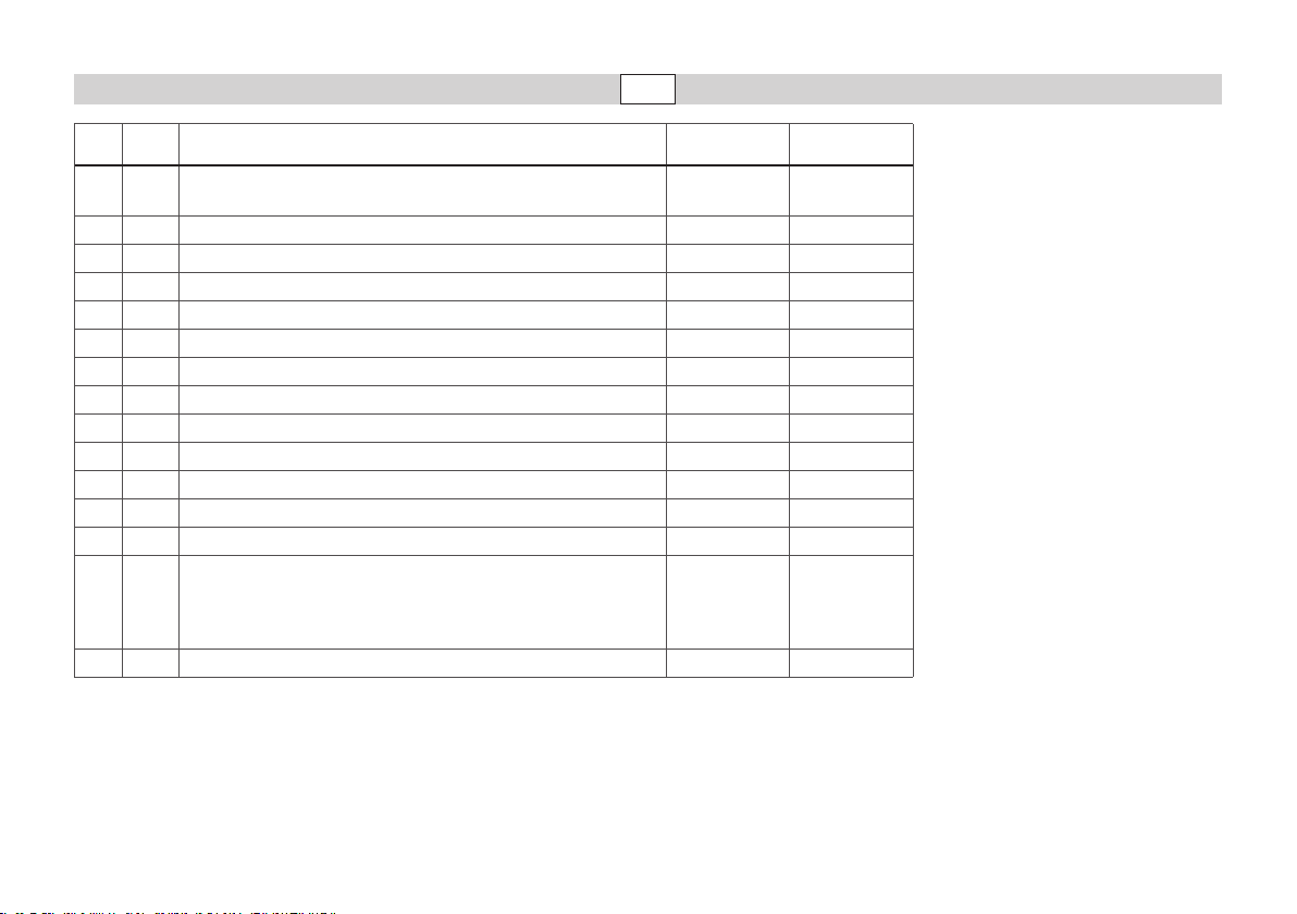
CV Discription 6021 Value DCC Value
01 Address 01 - 80
02 PoM Minimum Speed — 0 - 255 (25)
03 PoM Acceleration delay 01 - 63 0 - 255 (15)
04 PoM Braking delay 01 - 63 0 - 255 (15)
05 PoM Maximum speed 01 - 63 0 - 255 (255)
08 Factory Reset / Manufacturer Recognition 08 08 (131)
13 PoM Functions F1 - F8 in analog operation — 0 - 255 (0)
14 PoM Functions F9 - F15 and lights in analog operation — 0 - 255 (1)
17 Extended address (upper part CV29 Bit 5 = 1) — 193 - 255 (192)
18 Extended address (lower part CV29 Bit 5 = 1) — 0 - 255 (128)
19 Multiple Unit Address — 0 - 255 (0)
21 PoM Functions F1 - F8 on Multiple Unit — 0 - 255 (6)
22 PoM Functions F9 - F15 and lights on Multiple Unit — 0 - 255 (0)
Bit 0: Reversing direction
29
63 Volume 01 - 63 0 - 255 (255)
( ) Values = factory settings
DCC: programming on the programming track by means of CV programming, programming with PoM (Program on the Main);
* The values for the desired setting must be added!
Bit 1: Number of speed levels 14 or 28/128
Bit 2: DCC operation with braking area
Bit 5: Address length 7 Bit / 14 Bit
this must be supported by the controller you are using.
Example: The number of speed levels 28/128 = 2 + DCC operation with a braking route = 4, results in the value = 6
—
1 - 127 (03)
CV 29/Bit5 =0
0 / 1 (0)*
0 / 2 (2)*
0 / 4 (4)*
0 / 32 (0)*
Page 9

Remarques importantes sur la sécurité
• La locomotive ne peut être mise en service qu’avec un système
d’exploitation adéquat (DC = 18V ±, Märklin AC, Märklin Digital ou
Märklin Systems, DCC).
• Utiliser uniquement des convertisseurs et transformateurs correspondant à la tension du secteur local.
• La locomotive ne peut être alimentée en courant que par une seule
source de courant.
• Veuillez impérativement respecter les remarques sur la sécurité
décrites dans le mode d’emploi de votre système d’exploitation.
• Pour l’exploitation de la locomotive en mode conventionnel, la voie
de raccordement doit être déparasitée. A cet effet, utiliser le set de
déparasitage réf. 104 770. Le set de déparasitage ne convient pas
pour l’exploitation en mode numérique.
• Le câble de raccordement à la voie utilisé ne doit en aucun cas
dépasser deux mètres.
ATTENTION! Pointes et bords coupants lors du fonctionnement du
•
produit.
Informations générales
• La notice d‘utilisation fait partie intégrante du produit ; elle doit donc
être conservée et, le cas échéant, transmise avec le produit.
• Pour toute réparation ou remplacement de pièces, adresses-vous à
votre détaillant-spécialiste Märklin.
• http://www.maerklin.com/en/imprint.html
Tout recours à une garantie commerciale ou contractuelle ou à une demande de
dommages-intérêt est exclu si des pièces non autorisées par Märklin sont intégrées dans
les produits Märklin et / ou si les produits Märklin sont transformés et si les pièces d’autres
fabricants montées ou la transformation constituent la cause des défauts et / ou dommages
apparus. C’est à la personne et / ou la société responsable du montage / de la transformation ou au client qu’incombe la charge de prouver que le montage des pièces d’autres
fabricants sur des produits Märklin ou la transformation des produits Märklin n’est pas à
l’origine des défauts et ou dommages apparus.
Fonctionnement
• Le mode d’exploitation (Mfx, Märklin-Motorola ou DCC) est identié
automatiquement.
• Adresses pouvant être paramétrées :
Märklin 01 – 255 / Control Unit 1 – 80, DCC 01 - 9999
• Adresse départ usine : (Märklin) 32 / (DCC) 03
• Technologie Mfx pour Mobile Station / Central Station.
Nom encodee en usine: BR 332 255-9
• Temporisation d’accélération réglable (ABV).
• Temporisation de freinage réglable (ABV).
• Vitesse maximale réglable.
• Volume des bruitages réglable.
• Paramétrer les paramètres des locomotives (adresse, retardement
au démarrage / au freinage, vitesse maximale etc.) avec Control Unit
et DCC (programmation CV), Mobile Station ou Central Station.
• Electronique de bruitage intégrée, ne peut être utilisée qu’en étant
exploitée avec Märklin Digital, Märklin Systems ou DCC.
• Le modèle réduit est conçu pour rouler sur des voies Märklin 1. Le
faire rouler sur des voies d’autres systèmes comporte des risques.
• Rayon minimal d’inscription en courbe: 1020 mm.
• En mode d’exploitation analogique, seules les fonctions relatives à la
conduite et à l‘inversion des feux sont disponibles.
• Indication pour l’exploitation avec la Mobile Station :
Lorsque le besoin en puissance est très élevé et permanent, la Mobile Station coupe l’alimentation, comme lors d’un court-circuit. Le cas
échéant, réduisez le nombre de fonctions et redémarrez ensuite le
système en appuyant sur la touche STOP.
9
Page 10
10
f0 - f3 f4 - f7
mobile station
5
systems
f0 f8 f0f8
1
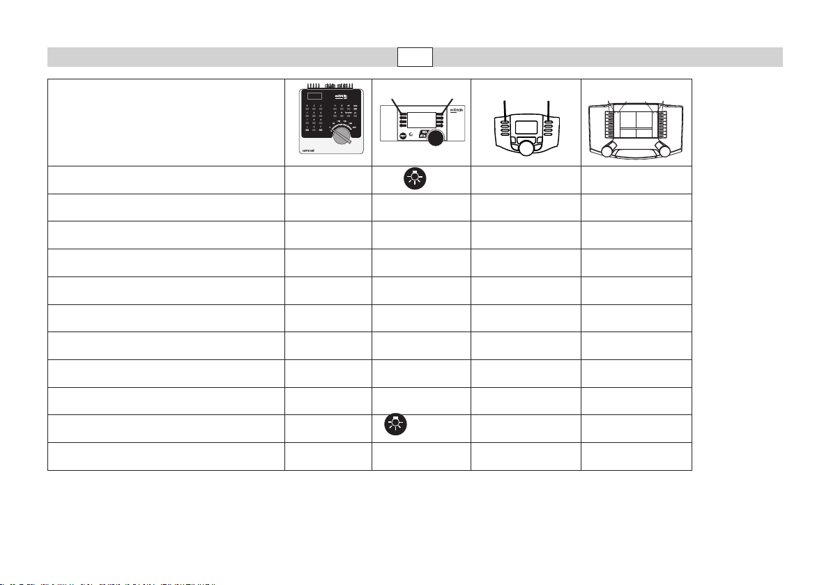
Fonctions commutables
STOP
Fanal function/off Fonction f0 Fonction f0
Attelage Telex à l’avant f1 Fonction 6 Fonction f1 Fonction f1
Bruit d’exploitation f2 Fonction 2 Fonction f2 Fonction f2
Bruitage : Trompe f3 Fonction 5 Fonction f3 Fonction f3
Attelage Telex à l’arrière f4 Fonction 3 Fonction f4 Fonction f4
Bruitage : Grincement de freins désactivé — Fonction 7 Fonction f5 Fonction f5
Fanal à l’arrière, éteint — Fonction 1 Fonction f6 Fonction f6
Fanal à l’avant, éteint — Fonction 8 Fonction f7 Fonction f7
ABV — Fonction 4 Fonction f8 Fonction f8
Bruitage : Bruit d’attelage — — Fonction f9 Fonction f9
Feu de manœuvre double A — + 1 + 8 f0 + f6 + f7 f0 + f6 + f7
Page 11
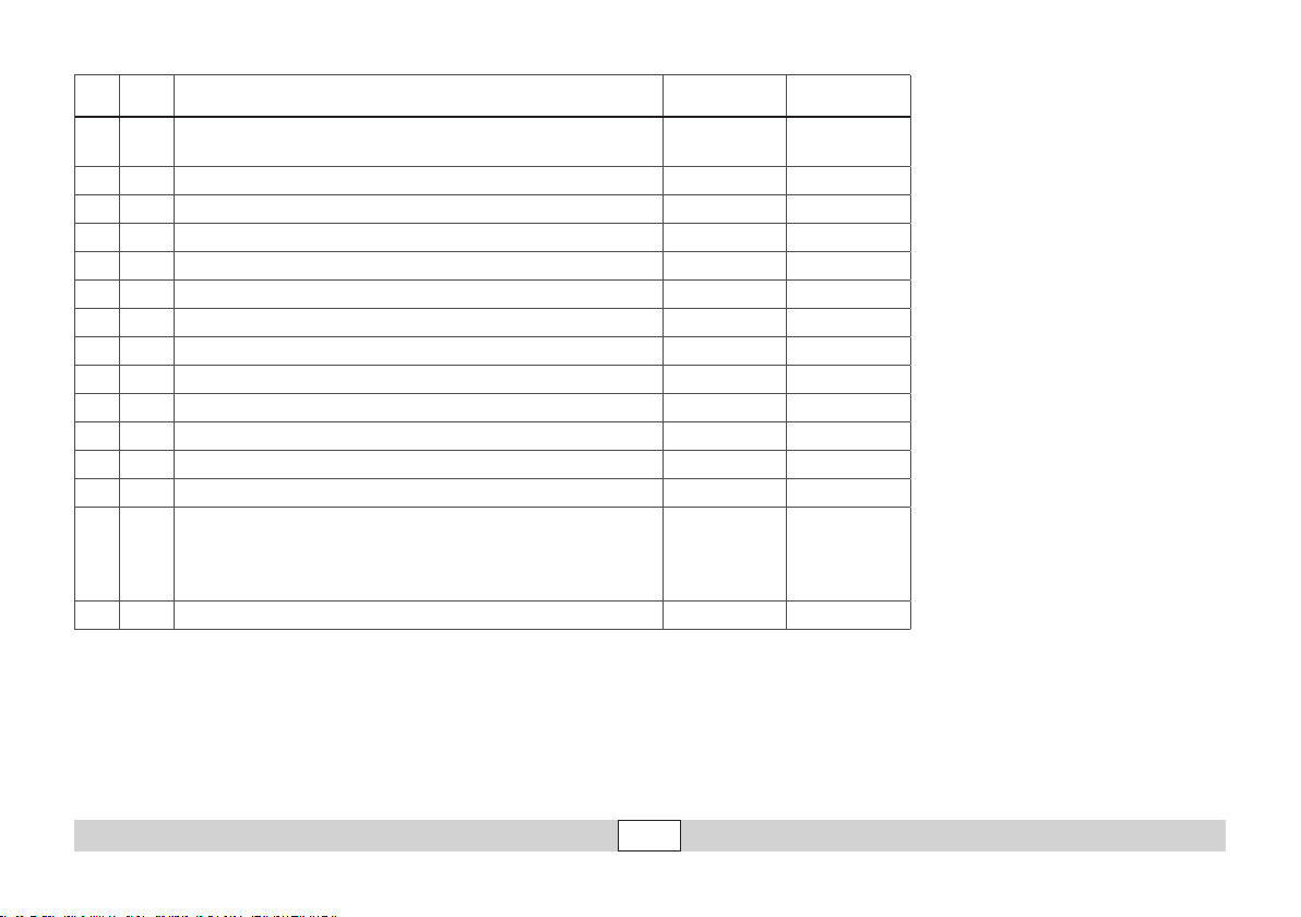
CV Affectation 6021 Valeur DCC Valeur
01 Adresse 01 - 80
02 PoM Vitesse min — 0 - 255 (25)
03 PoM Temporisation d‘accélération 01 - 63 0 - 255 (15)
04 PoM Temporisation de freinage 01 - 63 0 - 255 (15)
05 PoM Vitesse maximale 01 - 63 0 - 255 (255)
08 Réinitialisation d’usine/identication du fabricant 08 08 (131)
13 PoM Fonctions F1 - F8 en mode analog — 0 - 255 (0)
14 PoM Fonctions F9 - F15 et éclairage en mode analog — 0 - 255 (1)
17 Adresse étendue (partie supérieure CV29 Bit 5 = 1) — 193 - 255 (192)
18 Adresse étendue (partie inférieure CV29 Bit 5 = 1) — 0 - 255 (128)
19 Adresse traction — 0 - 255 (0)
21 PoM Fonctions F1 - F8 pour traction — 0 - 255 (6)
22 PoM Fonctions F9 - F15 et éclairage traction — 0 - 255 (0)
Bit 0: Inv. polarité Sens de marche
29
63 Volume 01 - 63 (63) 0 - 255 (255)
( ) Valeurs = paramétrage départ usine
DCC : programmer sur la voie de programmation au moyen de la programmation CV, programmer avec PoM (Program on the Main) ;
* Il convient d’additionner les valeurs des paramétrages souhaités !
Bit 1: Nombre de crans de marche 14 ou 28/128
Mode DCC avec dist. de freinage
Bit 2:
Bit 5: Capacité d’adresses 7 Bit / 14 Bit
ceci doit être supporté par le dispositif de commande.
P. ex. le nombre des crans de marche 28/128 = 2 + DCC Exploitation avec distance de freinage = 4, donne la valeur = 6
—
1 - 127 (03)
CV 29/Bit5 =0
0 / 1 (0)*
0 / 2 (2)*
0 / 4 (4)*
0 / 32 (0)*
11
Page 12

12
Veiligheidsvoorschriften
•
De loc mag alleen met een daarvoor bestemd bedrijfssysteem (DC
=18V ±, Märklin AC, Märklin digitaal, DCC of Märklin Systems) gebruikt
worden.
• Alleen net-adapters en transformatoren gebruiken waarvan de aangegeven netspanning overeenkomt met de netspanning ter plaatse.
• De loc mag niet vanuit meer dan één stroomvoorziening gelijktijdig
gevoed worden.
• Lees ook aandachtig de veiligheidsvoorschriften in de gebruiksaanwijzing van uw bedrijfssysteem.
• Voor het conventionele bedrijf met de loc dient de aansluitrail te
worden ontstoort. Hiervoor dient men de ontstoor-set 104 770 te
gebruiken. Voor het digitale bedrijf is deze ontstoor-set niet geschikt.
• De gebruikte aansluitkabel mag maximaal 2 meter lang zijn.
• OPGEPAST! Functionele scherpe kanten en punten.
Algemene informatie
• De gebruiksaanwijzing is een essentieel onderdeel van het product
en dient daarom bewaard te worden en bij het overdragen van het
product meegegeven te worden.
Voor reparatie of onderdelen kunt u zich tot uw Märklin handelaar
•
wenden.
• http://www.maerklin.com/en/imprint.html
Elke aanspraak op garantie en schadevergoeding is uitgesloten, wanneer in Märklin-
producten niet door Märklin vrijgegeven vreemde onderdelen ingebouwd en / of Märklin-
producten omgebouwd worden en de ingebouwde vreemde onderdelen resp. de ombouw
oorzaak van nadien opgetreden defecten en / of schade was. De aantoonplicht en de
bewijslijst daaromtrent, dat de inbouw van vreemde onderdelen in Märklin-producten of de
ombouw van Märklin-producten niet de oorzaak van opgetreden defecten en / of schade
is geweest, berust bij de voor de inbouw en/of ombouw verantwoordelijke persoon en / of
rma danwel bij de klant.
Functies
• Le mode d’exploitation (Mfx, Märklin-Motorola ou DCC) est identié
automatiquement.
• Adresses pouvant être paramétrées :
Märklin 01 – 255 / Control Unit 1 – 80, DCC 01 - 9999
• Adresse départ usine : (Märklin) 32 / (DCC) 03
• Mfx-technologie voor het Mobile Station / Central Station.
Naam af de fabriek: BR 332 255-9
• Instelbare optrekvertraging (ABV).
• Instelbare afremvertraging (ABV).
• Instelbare maximumsnelheid.
• Volume van de geluiden instelbaar.
• Instellen van de loc-parameters (adres, optrek-/afremvertraging,
maximumsnelheid enz.) met Control Unit en DCC (CV programmering),
Mobile Station of Central Station.
• Ingebouwde geluidselektronica, alleen te gebruiken met
Märklin digitaal, Märklin systems of DCC.
• Het model is ontwikkeld voor het gebruik op het Märklin Spoor 1
railsysteem. Het gebruik op een ander railsysteem geschied op eigen
risico.
• Berijdbare minimumradius: 1020 mm.
• In analoogbedrijf zijn alleen de rij- en lichtwissel-functies beschik-
baar.
• Opmerking voor het bedrijf met het Mobile Station.
Bij een voortdurend zeer hoge vermogensbehoefte schakelt het
Mobile Station, net als bij een kortsluiting, geheel uit. Verminder in
dat geval het aantal ingeschakelde functies en schakel het systeem
weer opnieuw in door de STOP-toets weer in te drukken.
Page 13
f0 - f3 f4 - f7
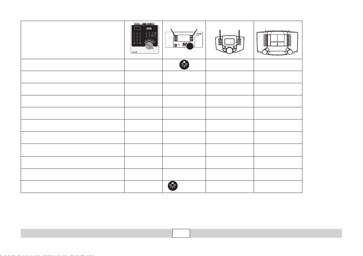
Schakelbare functies
1
STOP
mobile station
5
systems
f0 f8 f0f8
Frontverlichting function/off Functie f0 Functie f0
Telex-koppeling voor f1 Functie 6 Functie f1 Functie f1
Bedrijfsgeluiden f2 Functie 2 Functie f2 Functie f2
Geluid: signaalhoorn f3 Functie 5 Functie f3 Functie f3
Telex-koppeling achter f4 Functie 3 Functie f4 Functie f4
Geluid: piepende remmen uit — Functie 7 Functie f5 Functie f5
Frontverlichting achter uit — Functie 1 Functie f6 Functie f6
Frontverlichting voor uit — Functie 8 Functie f7 Functie f7
ABV — Functie 4 Functie f8 Functie f8
Geluid: koppelingsgeluid — — Functie f9 Functie f9
Rangeerlicht dubbel A — + 1 +8 f0 + f6 + f7 f0 + f6 + f7
13
Page 14
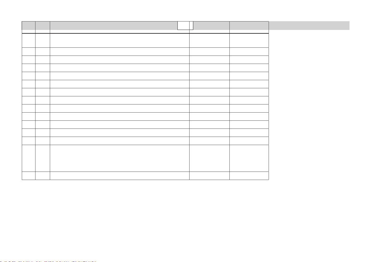
CV Betekenis Waarde 6021 Waarde DCC
01 Adres 01 - 80
02 PoM minimale snelheid — 0 - 255 (25)
03 PoM Optrekvertraging 01 - 63 0 - 255 (15)
04 PoM Afremvertraging 01 - 63 0 - 255 (15)
05 PoM Maximumsnelheid 01 - 63 0 - 255 (255)
08 Fabrieksinstelling/fabriekherkenning 08 08 (131)
13 PoM functies F1 - F8 in analoogbedrijf — 0 - 255 (0)
14 PoM functies F9 - F15 en licht in analoogbedrijf — 0 - 255 (1)
17 Uitgebreld adres (bovenste gedeelte CV29 Bit 5 = 1) — 193 - 255 (192)
18 Uitgebreld adres (onderste gedeelte CV29 Bit 5 = 1) — 0 - 255 (128)
19 tractieadres — 0 - 255 (0)
21 PoM functies F1 - F8 in tractie — 0 - 255 (6)
22 PoM functies F9 - F15 en licht in tractie — 0 - 255 (0)
Bit 0: ompolen rijrichting
29
63 Volume 01 - 63 0 - 255 (255)
( ) waarde = fabrieksinstelling
DCC: programmeren op het programmeerspoor door middel van CV programmering, programmeren met PoM (Program on the Main);
* De waarden van de gewenste instellingen dienen bij elkaar opgeteld te worden!
Bit 1: aantal rijstappen 14 of 28/128
Bit 2: DCC bedrijf met afremtraject
Bit 5: adresomvang 7 Bit / 14 Bit
dit dient door het besturingsapparaat ondersteund te worden.
Bijv. aantal rijstappen 28/128 = 2 + DCC bedrijf met afremtraject = 4, geeft een waarde van 2+4=6
14
—
1 - 127 (03)
CV 29/Bit5 =0
0 / 1 (0)*
0 / 2 (2)*
0 / 4 (4)*
0 / 32 (0)*
Page 15

Anschluss der Gleisanlage
Um Spannungsverluste auf der
Anlage zu vermeiden, ist immer
auf gutes Zusammenpassen der
Schienenverbindungslaschen
zu achten. Alle 2 bis 3 m ist eine
neue Strom-einspeisung über die
Anschlussklemmen 5654 empfehlenswert.
Befahren von Steigungen
Im Gegensatz zum Vorbild können
mit einer Modellbahn auch größe-
re Steigungen befahren werden.
Im Normalfall sollte eine Steigung
bei maximal 3 Prozent liegen. Im
Extremfall sind bei entsprechend
eingeschränkter Zugleistung maximal 5 Prozent möglich. Der Anfang und das Ende der Steigung
sind auf jeden Fall auszurunden.
Der Unterschied in der Steigung,
zwischen zwei mindestens 300 mm
langen Gleisstücken, darf maximal
1 bis 1,5 Prozent betragen.
Prinzipbedingt ist die Zugkraft die-
ses Modells eingeschränkt. Die
maximal befahrbare Steigung mit
2 bis 3 zweiachsigen Güterwagen
liegt bei ca. 3 %.
Connections track layout
Rail joiners must t well on the rails
of the track to which they are joined
to avoid voltage drop on the layout.
We recommend that you install feeder wires every 2 to 3 meters (7 to
10 feet) using the 5654 feeder clips.
Operating the locomotive
on grades
In contrast to the prototype a locomotive on a model railroad can
operate up steeper grades. As a
general rule a grade should be no
steeper than 3%. In extreme situations a maximum grade of 5% is
permissible, keeping in mind that
the locomotive’s tractive effort
will be less. The beginning and
the end of the grade must always
work gradually up to maximum
grade for the route.
The maximum allowable difference in grade between two track
sections, each with a minimum
length of 300 mm (11-3/4“) is 1 to
1.5 percent.
In principle the pulling power for
this model is limited. The maximum
grade it can negotiate with 2 to 3
twoaxle freight cars is about 3 %.
Connexion des voies ferrées
Pour éviter des pertes de potentiel sur l’installation, il faut veiller
à ce que les éclisses de liaison
des rails soient toujours parfaitement adaptées. Une nouvelle
alimentation électrique est conseillée tous les 2 à 3 m au moyen
des griffes d’alimentation 5654.
Franchissement des côtes
Contrairement à l’original, la
maquette est également en me-
sure de franchir des côtes assez
importantes. En temps normal,
une côte devrait étre de l’ordre de
3% maximum. A l’extrême limite,
5% sont envisageables avec une
puissance du train réduite en
consequence. Le début et la n
de la côte doivent en tous cas
étre arrondis.
La différence de pente entre
deux éléments de voie d’au moins 300 mm de longueur doit étre
de 1 à 1,5% maximum.
En principe, la puissance de
traction de ce modèle réduit est
limitée. La rampe maximale que
la locomotive peut grimper avec
2 à 3 wagons à deux essieux est
d’environ 3 %.
Aansluiting van de sporen
Om spanningsverlies op de
modelbaan te voorkomen moeten
de raillassen altijd goed op elkaar
aansluiten. Om de 2 à 3 meter
moet de voeding opnieuw op de
rails gezet worden. Daarbij zijn
de aansluitklemmen 5654 aan te
raden.
Berijden van hellingen
In tegenstelling tot het grote voorbeeld kunnen met een modelbaan
ook grotere hellingen bereden
worden. Normaal moet een
helling maximaal 3 procent zijn.
In extreme gevallen is maximaal 5
procent mogelijk, maar dan moet
rekening gehouden worden met
een evenredig verlies aan vermogen. Het begin en het einde van
de helling moeten altijd gerond
worden.
Het verschil in de helling tussen
twee tenminste 300 mm lange
railstukken mag maximaal 1 à 1,5
procent bedragen.
Vanwege de uitvoering is de
trekkracht van dit model beperkt.
De maximale berijdbare stijging
met 2 of 3 goederenwagens ligt bij
ongeveer 3%.
15
Page 16
16
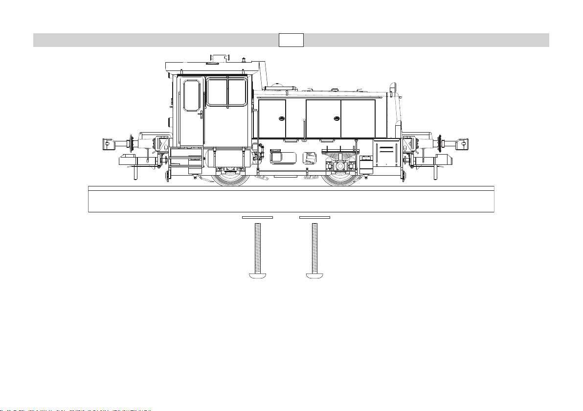
Aus Sicherheitsgründen ist dieses
schwere und detaillierte Modell
auf dem mitgelieferten Sockel
angeschraubt. Bitte entfernen Sie
die 2 Schrauben sehr vorsichtig
und bewahren Sie sie auf. Bitte
transportieren Sie die Lokomotive
nur auf diesem Sockel gesichert
in der zugehörigen Originalkassette.
For safety reasons, this heavy and
detailed model is screwed to the
supplied base. Please remove the
2 screws very carefully and keep
them safe. When moving the locomotive, transport it only on this
base and in the original case.
Pour des raisons de sécurité,
ce modèle lourd et pourvu de
nombreux détails est livré vissé
sur un socle. Retirez les 2 vis,
avec la précaution qui s’impose
et conservez-les. Ne transportez
la locomotive que vissée sur ce
socle et rangée dans la cassette
d’origine correspondante.
Om veiligheidsredenen is dit
zware en gedetailleerde model op de bijgeleverde sokkel
vastgeschroefd. Verwijder de 2
schroeven voorzichtig en bewaar
deze zorgvuldig. Transporteer de
locomotief uitsluitend in geborg-
de toestand, d.w.z. vastgezet op
de sokkel, in de bijbehorende
originele cassette.
Page 17
4
3
1
5
2
17
Page 18
40h
18
Page 19
5
1
4
2
3
19
Page 20
This device complies with Part 15 of the FCC Rules.
Operation is subject to the following two conditions:
(1) This device may not cause harmful interference, and
(2) this device must accept any interference received, including
interference that may cause undesired operation.
Gebr. Märklin & Cie. GmbH
Stuttgarter Str. 55 - 57
73033 Göppingen
Deutschland
www.maerklin.com
www.maerklin.com/en/imprint.html
157213/1210/Ha1Kb
Änderungen vorbehalten
© by Gebr. Märklin & Cie GmbH
 Loading...