

Page 1
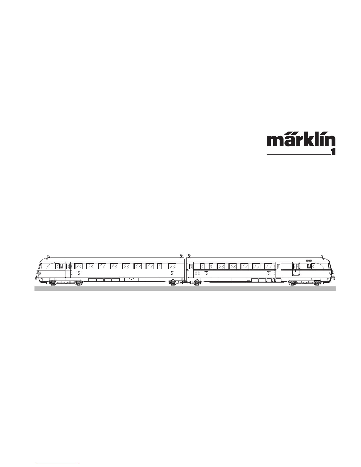
Modell des SVT 137
55137
Page 2

2
Informationen zum Vorbild
In den 20er- und 30er-Jahren des 20. Jahrhunderts war das Ziel
der DRG, die deutschen Großstädte mit immer schnelleren Zugverbindungen zu bedienen.
Eine Lösung hierzu war der Diesel-Triebwagenzug„Fliegender Ham
burger“, der ab Mai 1933 Berlin und Hamburg miteinander verband.
Durch die Höchstgeschwindigkeit von 160 km/h (bei Versuchs
fahrten wurden sogar 175 km/h erreicht) und dem Einsparen von
Zwischenhalten bei diesem Zug war die Fahrt zwischen den beiden
Metropolen auch für Tagesreisen interessant geworden. Insgesamt
wurde für die knapp 290 km lange Strecke eine Zeit von unter
2 1/2 Stunden benötigt. Ab 1935 wurden insgesamt 13 weitere
Garnituren dieses Zuges hergestellt, bei deren Ausführung bereits
viele Verbesserungen gegenüber dem Prototypen berücksichtigt
wurden. Dies ist am auffälligsten an der geänderten Kopfform.
Eingesetzt wurden diese Garnituren von Anfang an auf verschiedenen Strecken in Deutschland und nicht nur nach Hamburg, was der
Name ja schnell assoziiert.
Information about the prototype
In the 1920s and 1930s the DRG’s goal was to serve the larger
German cities with faster and faster train connections.
One solution for this was the “Fliegender Hamburger” or “Flying
Hamburg” diesel powered rail car train, which linked Berlin and
Hamburg with each other starting in May of 1933. The trip between
these two major cities became interesting for day trips because of
the maximum speed of 160 km/h or 100 mph (on test runs
175 km/h or 109 mph was even reached) and the savings in time
from not having intermediate stops on this train. Under 2-1/2 hours
was required for the barely 290 km or 181 mile long route. Starting
in 1935 a total of 13 additional sets of this train was built, with
many improvements made compared to the prototype train. The
most striking of these changes is the different shape to the ends of
the train. These train sets were used right from the start on different
routes in Germany and not only to Hamburg, with which the train’s
name was quickly associated.
Page 3

3
Informations concernant la locomotive réele
Au cours de années 20 et 30 du 20e siècle, le but de la DRG était
de créer des relations toujours plus rapides entre les grandes
métropoles allemandes.
La solution retenue fut la création de la rame automotrice diesel
„Fliegender Hamburger“ (Hambourgeois volant) dont la mise en
service eut lieu en mai 1933 entre Berlin et Hambourg. Grâce à
la vitesse de 160 km/h (la vitesse maximale atteinte au cours des
essais a été de 175 km/h) et à l’absence d’arrêts intermédiaires,
le voyage entre les deux grandes villes était devenu intéressant,
même pour des voyages quotidiens. Les 290 km de ce long
parcours étaient couverts en tout juste 2 1/2 heures. Treize autres
rames ont été construites partir de 1935. Par rapport au prototype,
elles avaient bénéficié lors de leur construction d’une série d’améliorations dont la plus frappante concernait la forme des faces
frontales. Ces rames ont été mises en service dès le début sur
différentes lignes de l’Allemagne et non pas seulement vers Ham
-
bourg malgré ce que le surnom de la rame pourrait laisser croire.
Informatie van het voorbeeld
In de twintiger en dertiger jaren van de twintigste eeuw was de
doelstelling van de DRG de grote steden in Duitsland van een
steeds snellere treinverbinding te voorzien.
Een van de oplossingen hiervoor was de “Fliegender Hamburger”,
die vanaf mei 1933 Berlijn en Hamburg met elkaar verbond. Door
een maximumsnelheid van 160 km/h (tijdens proefritten werd zelfs
175 km/h bereikt) en het laten vervallen van tussenstops bij deze
trein was een rit tussen deze beide metropolen ook voor een dagtrip interessant geworden. In totaal duurde de rit over het bijna
290 km traject minder dan 2 1/2 uur. Vanaf 1935 werden in totaal
nog 13 treinen van dit type gebouwd waarbij ten opzichte van het
prototype al veel verbeteringen doorgevoerd werden. Dit valt het
meest op aan het gewijzigde front van de trein. Van aanvang aan
werd deze trein op verschillende trajecten in Duitsland ingezet en
niet alleen naar Hamburg, ondanks dat de naam van de trein hier
-
mee al snel wordt geassocieerd.
Page 4
4
1.
1.
2.
2.
1.
1.
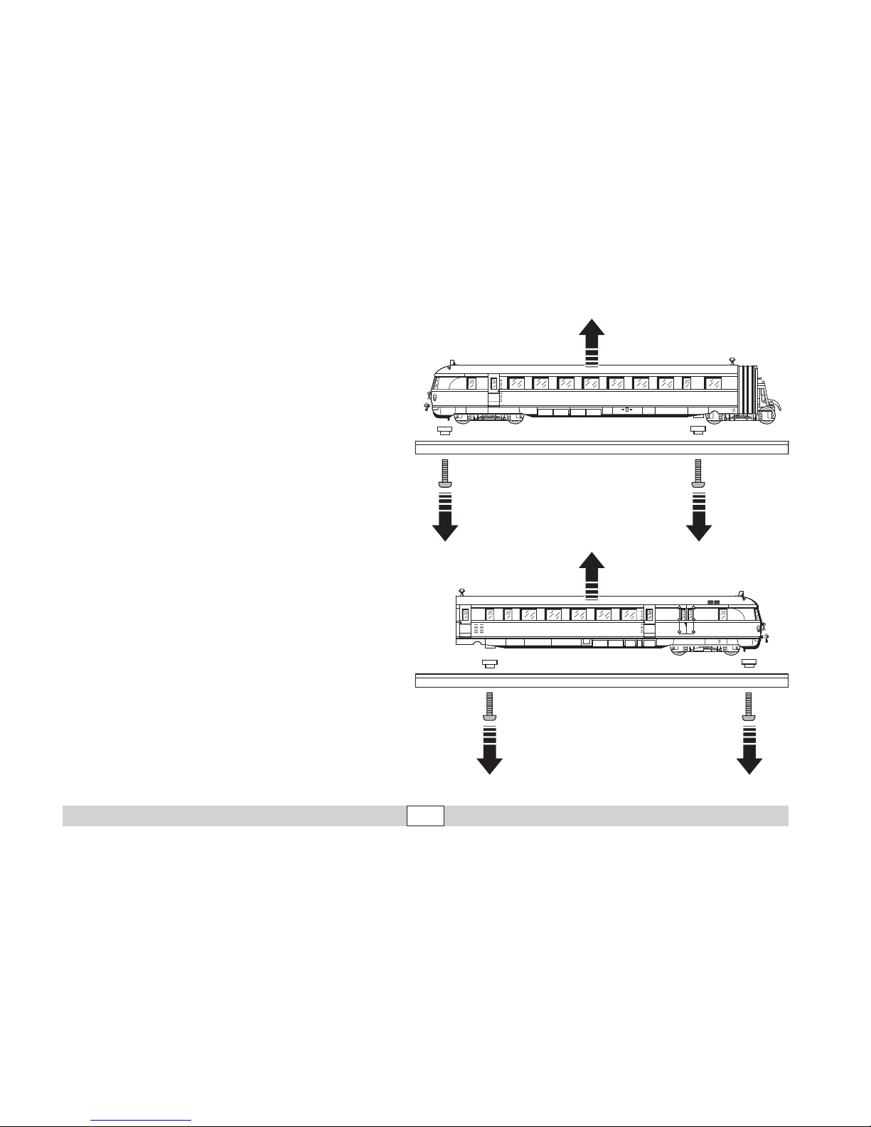
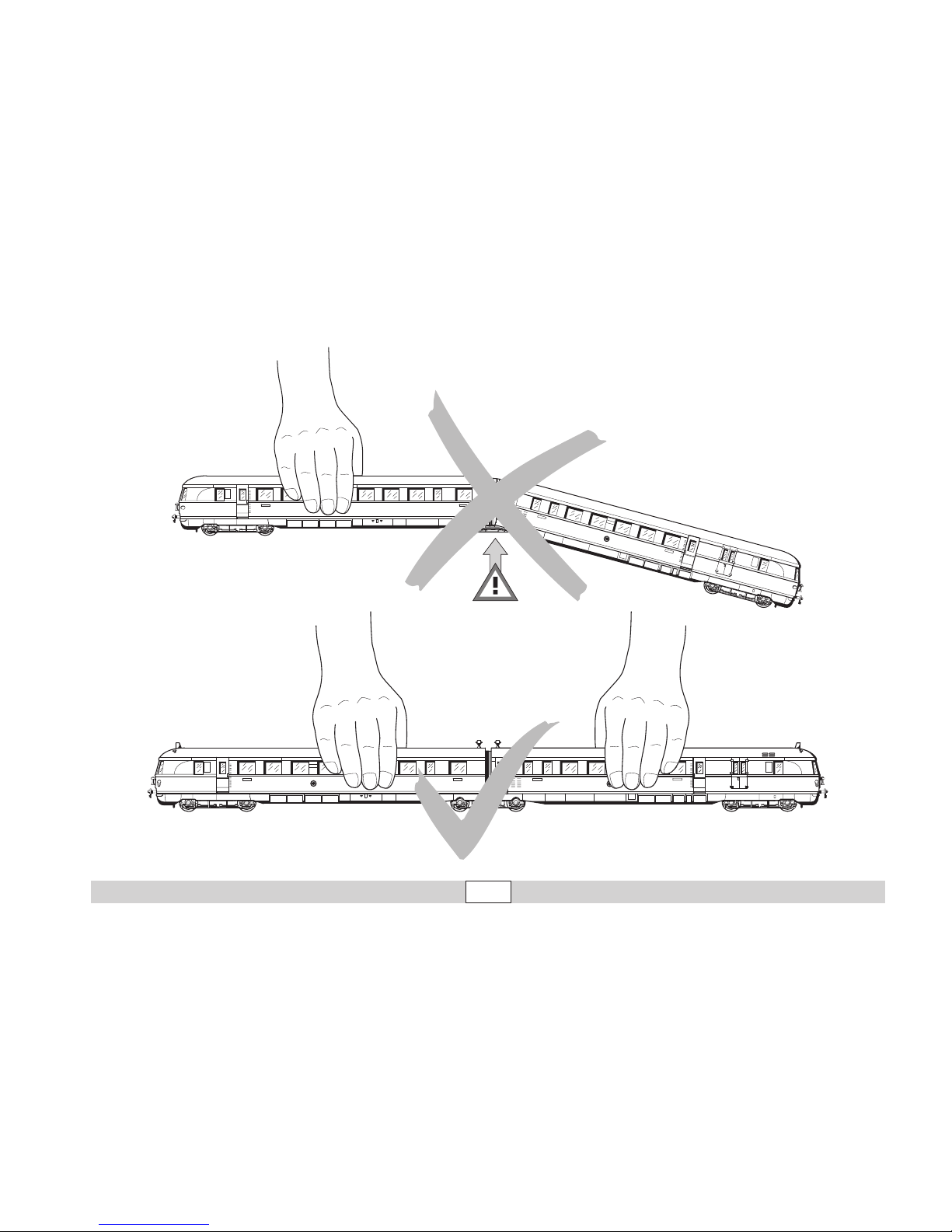
Aus Sicherheitsgründen ist dieses schwere und detaillierte
Modell auf dem mitgelieferten Sockel angeschraubt. Bitte entfernen Sie die 5 Schrauben sehr vorsichtig und bewahren Sie
sie auf. Bitte transportieren Sie die Lokomotive nur auf diesem
Sockel gesichert in der zugehörigen Originalkassette.
For safety reasons, this heavy and detailed model is screwed
to the supplied base. Please remove the 5 screws very careful
ly and keep them safe. When moving the locomotive, transport
it only on this base and in the original case.
Pour des raisons de sécurité, ce modèle lourd et pourvu de
nombreux détails est livré vissé sur un socle. Retirez les 5 vis,
avec la précaution qui s’impose et conservez-les. Ne transportez la locomotive que vissée sur ce socle et rangée dans la
cassette d’origine correspondante.
Om veiligheidsredenen is dit zware en gedetailleerde model op
de bijgeleverde sokkel vastgeschroefd. Verwijder de 5 schroe
ven voorzichtig en bewaar deze zorgvuldig. Transporteer de
locomotief uitsluitend in geborgde toestand, d.w.z. vastgezet
op de sokkel, in de bijbehorende originele cassette.
Page 5

5
2.
1.
Dach in Pfeilrichtung schieben. Vorsichtig abheben, Kabel für Innenbeleuchtung beachten.
Push the roof in the direction of the arrow. Carefully lift the roof, and be careful of the wiring.
Faire coulisser le toit dans le sens des flèches. Soulever avec précaution en faisant attention aux fils de l’éclairage intérieur.
Dak in de pijlrichting schuiven. Voorzichtig oplichten, let op de draad van de binnenverlichting.
Faltenbalg nach oben
abheben.
Lift the diaphragm up.
Relever le soufflet
l’intercirculation.
Vouwbalg naar boven
losnemen.
Page 6
6
3.
4.
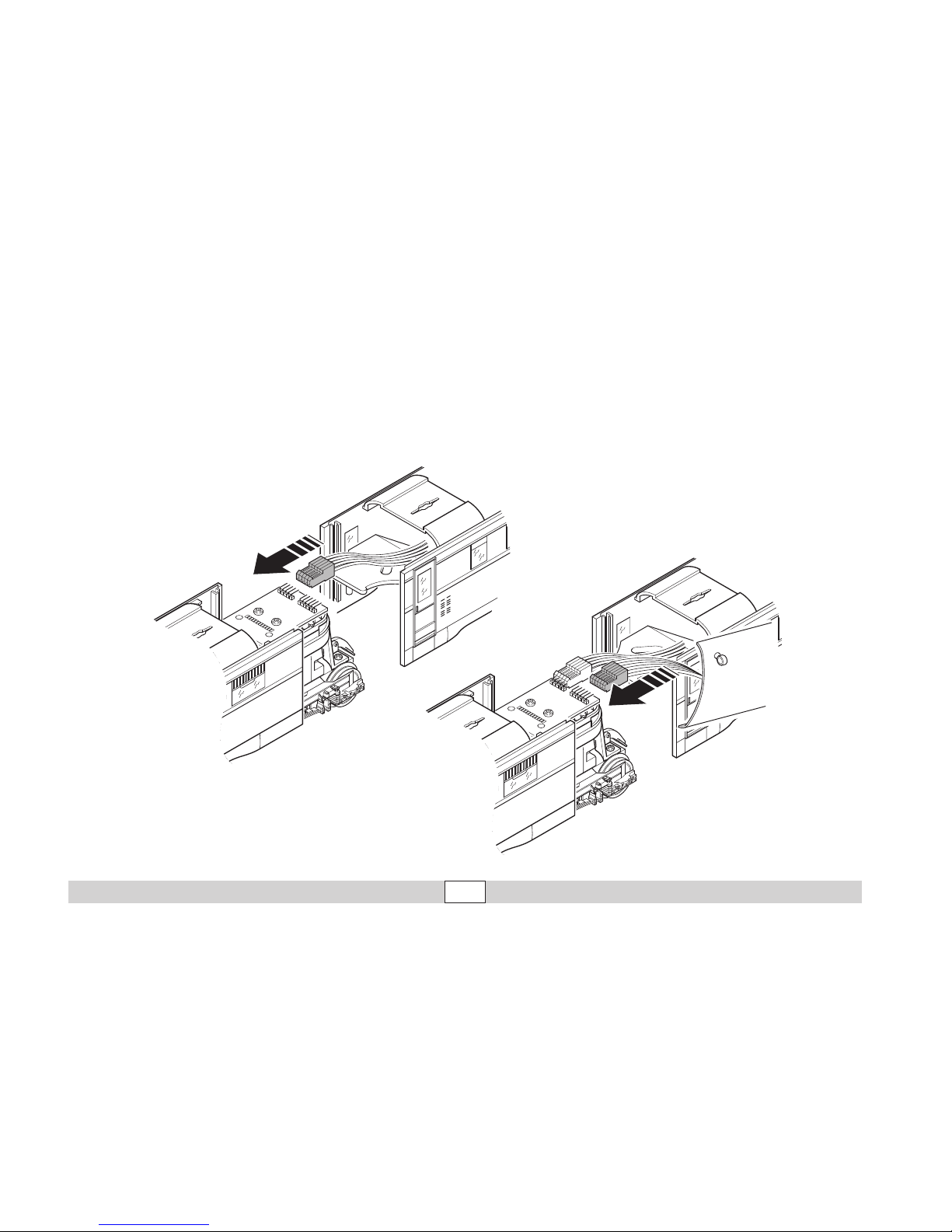
Buchse 5-polig und 6-polig vom Zugteil B auf die Stecker 5-polig und 6-polig vom Zugteil A stecken.
Stick the 5-pin and the 6-pin socket from train part B on the 5-pin and the 6-pin plug from train part A.
Enficher les connecteurs à 5 et 6 pôles de la partie A du train dans les douilles à 5 et 6 pôles de la partie B.
Vijf-polige en zes-polige stekkerbus van treindeel B op de vijf-polige en zes-polige stekker van treindeel A steken.
Page 7
7
5.
6.
Hinweis Mobile Station: Ist
der Leistungsbedarf dauerhaft zu hoch, so schaltet wie
bei einem Kurzschluss die
Mobile Station komplett ab.
Verringern Sie in diesem Fall
die Anzahl der Funktionen
und schalten Sie anschließend durch Drücken auf
die STOP-Taste das System
wieder ein.
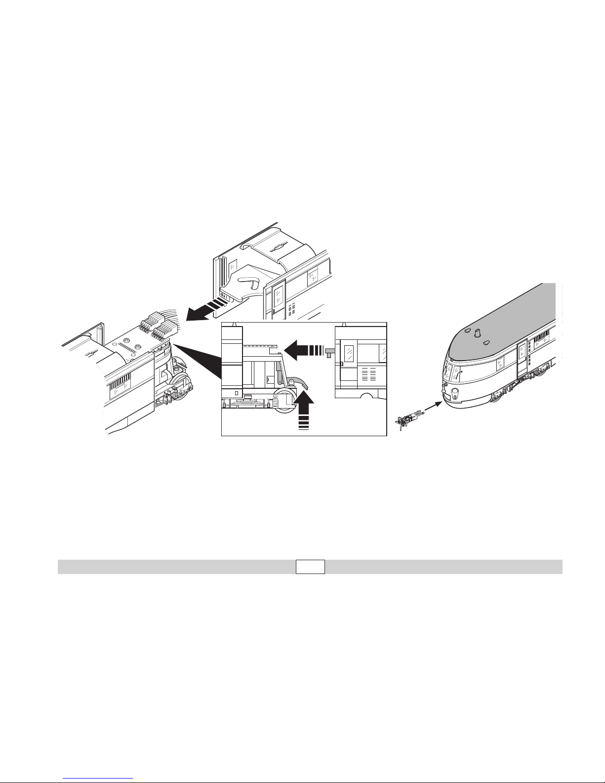
Vorbild-Kupplung zum Einstecken
Prototypical coupler for installation on
locomotive
Attelage modèle à fixer
Opsteekbare voorbeeld-koppeling
Note Mobile Station: If the
demand for power output
remains excessively high, the
Mobile Station completely
shuts down (as is the case
with a permanent short circuit). In this case, reduce the
number of mobile functions
and press the STOP button to
reactivate the system.
Remarque Mobile Station: Si
le besoin en puissance est
trop important en perma
nence, la Mobile Station se
désactive complètement
comme lors d’un courtcircuit
permanent. Dans ce cas,
réduisez le nombre de fonc
tions et ré-activez ensuite le
système en appuyant sur la
touche STOP.
N.B. Mobile Station: Is het
vermogensverbruik blijvend te
hoog, schakelt de mobile sta
tion net als bij een kortsluiting
compleet uit. Reduceer in dat
geval het aantal rijdende functies en schakel het systeem
vervolgens via indrukken van
de STOP-toets opnieuw in.
Page 8
8
8.
9.
7.
4x
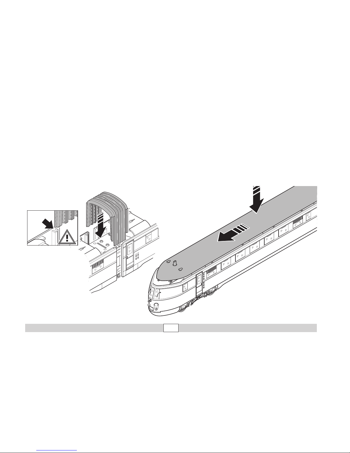
Zughälften zusammenschieben, bis der Faltenbalg auf
beide Hälften geschoben werden kann. Nuten des Faltenbalges auf Rippen am Gehäuseende einführen. Faltenbalg
vorsichtig und gleichmäßig
bis zum Anschlag nach unten
schieben.
Push the two halves of the train
together until the diaphragm
can pushed onto both halves.
Guide the slots on the dia
phragm onto ribs on the end of
the body. Carefully and gradual
ly push the diaphragm down to
the stop.
Rapprocher les deux parties du
train jusqu’à ce que le soufflet
d’intercirculation puisse être
glissé sur les deux moitiés.
Fixer les encoches du soufflet
d’intercirculation sur les nervu
res à l’extrémité de la caisse.
Faire coulisser le soufflet
d’intercirculation régulièrement
et avec précaution vers le bas
jusqu’à la butée.
De treindelen aan elkaar schuiven tot de vouwbalg op de
beide helften geschoven kan
worden. Sleuf van de vouwbalg
in de ribbel aan de kopzijde
van de kap schuiven. Vouwbalg voorzichtig en gelijkmatig
tot de aanslag naar beneden
schuiven.
Page 9
9
22
DEUTSCHE REICHSBAHN
137 150 a
Berlin
B6vT
93,4 t
77 PI
44,
256
m
Hikptbr
Raucher
Raucher
D
E
R
E
I
C
H
S
B
A
H
N
S
C
H
E
T
U
D
E
R
E
I
C
H
S
B
A
H
N
S
C
H
E
T
U
B6vT
93,
4
t
77 PI
44,
2
5
6
m
Hikptbr
Nichtra
ucher
Nichtra
ucher
2
2
DEUTSCHE
REICHS
BAHN
137 150
a
B
e
rli
n
Nichtraucher
Nichtraucher
2 222
DEUTSCHE REICHSBAHN
137 150 a
Berlin
B6vT
93,4 t
77 PI
44,256 m
Hikptbr
Raucher
Raucher
DEUTSCHE REICHSBAHN
137 150 a
Berlin
D
E
R
E
I
C
H
S
B
A
H
N
S
C
H
E
T
U
D
E
R
E
I
C
H
S
B
A
H
N
S
C
H
E
T
U
B6vT
93,4 t
77 PI
44,256 m
Hikptbr
Page 10

10
Funktion
Diese Lokomotive mit eingebauter Mehrzug-Elektronik bietet:
• Wahlweise Betrieb mit Gleichstrom (max ± 18 V=),
Wechselstrom (Märklin Transformer 32 VA), Märklin Delta
(nur Delta Station 6607), Märklin Digital (nur Control Unit)
oder Märklin Systems (Mobile Station, Central Station).
Ein Betrieb mit anderen Betriebssystemen (Impulsbreitensteuerung, Central Control 1 etc.) ist nicht möglich.
• Die Betriebsart wird automatisch erkannt.
• 80 Mehrzugadressen einstellbar. Adresse ab Werk:
37
• Mfx-Technologie für Mobile Station / Central Station.
Name ab Werk:
SVT 137
• Veränderbare Anfahrverzögerung (ABV).
• Veränderbare Bremsverzögerung (ABV).
• Veränderbare Höchstgeschwindigkeit.
• Veränderbare Lautstärke der Geräusche
• Einstellen der Lokparameter elektronisch über
Control Unit, Mobile Station oder Central Station.
• Eingebaute Geräuschelektronik, nur im Betrieb mit
Control Unit oder Märklin Systems nutzbar.
Zusätzliche schaltbare Geräusche.
• Das Modell ist für den Betrieb auf Märklin 1-Gleisen
entwickelt. Ein Betrieb auf anderen Gleissystemen
geschieht auf eigenes Risiko.
• Befahrbarer Mindestradius: 1020 mm
•
Bis auf die Stirnbeleuchtung sind die Funktionen in den
Betriebsarten Gleichstrom, Wechselstrom und Märklin
Delta ausgeschaltet.
Die bei normalem Betrieb anfallenden Wartungsarbeiten
sind
nachfolgend beschrieben. Für Reparaturen oder Ersatzteile
wenden Sie sich bitte an Ihren Märklin-Fachhändler.
Jegliche Garantie-, Gewährleistungs- und Schadensersatzansprüche sind ausgeschlossen, wenn in Märklin-Produkten nicht von Märklin freigegebene Fremdteile
eingebaut werden und / oder Märklin-Produkte umgebaut werden und die eingebauten Fremdteile bzw. der Umbau für sodann aufgetretene Mängel und/ oder
Schäden ursächlich war. Die Darlegungs- und Beweislast dafür, dass der Einbau
von Fremdteilen oder der Umbau in bzw. von Märklin-Produkten für aufgetretene
Mängel und / oder Schäden nicht ursächlich war, trägt die für den Ein- und / oder
Umbau verantwortliche Person und / oder Firma bzw. der Kunde.
Sicherheitshinweise
• Die Lok darf nur mit einem dafür bestimmten Betriebs-
system (Gleichstrom, Märklin Wechselstrom-Transformator 6647, Märklin Delta, Märklin Digital oder Märklin
Systems) eingesetzt werden. Keinesfalls Transformatoren
für eine Eingangsspannung von 220 V - für USA 110 V
- verwenden.
• Die Lok darf nur aus einer Leistungsquelle gleichzeitig
versorgt werden.
• Für den konventionellen Betrieb der Lok muss das
Anschlussgleis entstört werden. Dazu ist das Entstörset
104770 zu verwenden. Für Digitalbetrieb ist das Entstörset nicht geeignet.
• Beachten Sie unbedingt die Sicherheitshinweise in der
Gebrauchsanleitung zu Ihrem Betriebssystem.
Page 11
11
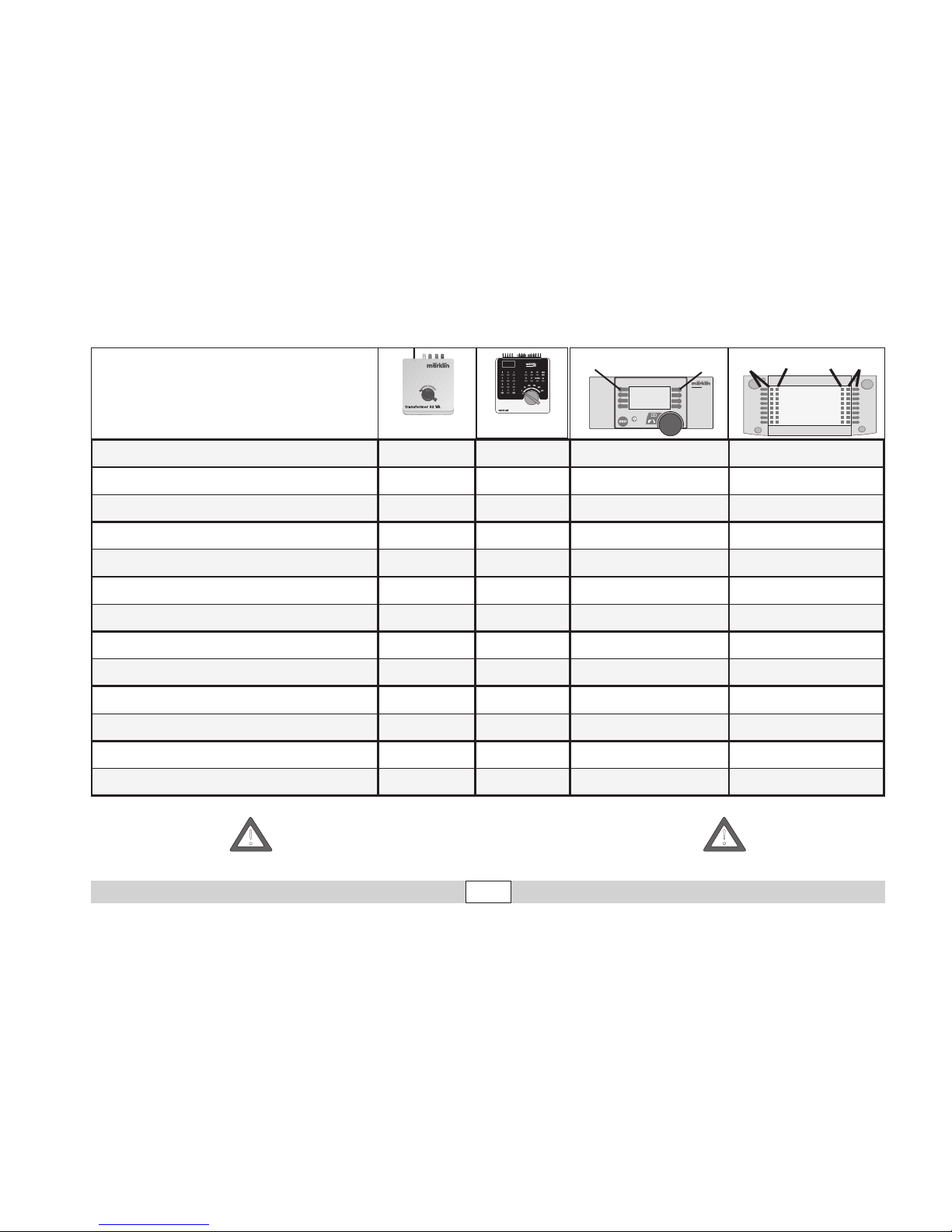
Schaltbare Funktionen
6647
6021
STOP
mobile station
systems
1
5
60652
central
station
60212
f0
f0f8
f8
Spitzensignal/Führerstandsbeleuchtung
Dauernd ein function + off Licht-Taste Taste f0 mit Symbol
Innenbeleuchtung
— f1 Taste 1 mit Symbol Taste f1 mit Symbol
Betriebsgeräusch
— f2 Taste 2 mit Symbol Taste f2 mit Symbol
Geräusch: Horn lang
— f3 Taste 6 mit Symbol Taste f3 mit Symbol
ABV
— f4 Taste 4 mit Symbol Taste f4 mit Symbol
Geräusch: Bahnhofsansage
— — Taste 3 mit Symbol Taste f5 mit Symbol
Geräusch: Schaffnerpfiff
— — Taste 8 mit Symbol Taste f6 mit Symbol
Geräusch: Horn kurz
— — Taste 5 mit Symbol Taste f7 mit Symbol
Geräusch: Türen öffnen
— — Taste 7 mit Symbol Taste f8 mit Symbol
Geräusch: Bremsenquietschen aus
— — — Taste f9 mit Symbol
Geräusch: Schienenstöße
— — — Taste f10 mit Symbol
Geräusch: Luftpumpe
— — — Taste f11 mit Symbol
Geräusch: Schmierpumpe
— — — Taste f12 mit Symbol
Uneingeschränkter Fahrbetrieb des Triebzuges mit den Funktionen function und f1-f4 ist nur mit der Control Unit 6021 möglich,
der volle Funktionsumfang nur mit der Central Station 60212.
!
!
Page 12

12
Function
This locomotive has a built-in multi-train electronic circuit
and offers these features:
• Optional operation with DC power (max. ± 18 volts DC),
AC power (with Märklin 32 VA transformer), with Märklin
Delta (only with the 6607 Delta Station), Märklin Digital
(only with the Control Unit), or Märklin Systems
(Mobile Station, Central Station).
• The mode of operation is automatically recognized.
• 80 multi-train addresses can be set. Address that set at
the factory: 37
• Mfx technology for the Mobile Station / Central Station.
Name set at factory:
SVT 137
• Adjustable acceleration (ABV).
• Adjustable Braking delay (ABV)
• Adjustable maximum speed.
• Volume can be changed for the sound effects
• Setting the locomotive parameters electronically with the
Control Unit, Mobile Station or Central Station.
• Built-in sound effects circuit, can only be used in opera
tion with the Control Unit or Märklin Systems. Additional
sound effects that can be controlled.
• The model is designed for operation on Märklin 1 Gauge
track. As the consumer you assume the risk for operating
on other makes of track.
• Minimum radius for operation: 1020 mm / 40-1/6“.
•
Except for the headlights all of the functions are off in the
modes of operation for DC power, AC power, and Märklin Delta.
Maintenance procedures that become necessary with normal
operation of the locomotive are described below. Please see your
authorized Märklin dealer for repairs or spare parts.
No warranty or damage claims shall be accepted in those cases where parts
neither manufactured nor approved by Märklin have been installed in Märklin
products or where Märklin products have been converted in such a way that the
non-Märklin parts or the conversion were causal to the defects and / or damage
arising. The burden of presenting evidence and the burden of proof thereof, that
the installation of non-Märklin parts or the conversion in or of Märklin products was
not causal to the defects and / or damage arising, is borne by the person and / or
company responsible for the installation and / or conversion, or by the customer.
Safety Warnings
• This locomotive is to be used only with an operating
system designed for it (Märklin 6646/6647 AC transformer, Märklin Delta, Märklin Digital or Märklin Systems).
Under no circumstances should transformers rated for an
input of 220 volts be connected to the American 110 volt
household current system
• This locomotive must never be supplied with power from
more than one transformer.
• The feeder track must be equipped to prevent interfer
ence with radio and television reception, when the powered rail car is to be run in conventional operation. The
104770 interference suppression set is to be used for this
purpose.The interference suppression set is not suitable
for digital operation.
• Pay close attention to the safety warnings in the instruc
-
tions for your operating system.
Page 13
13
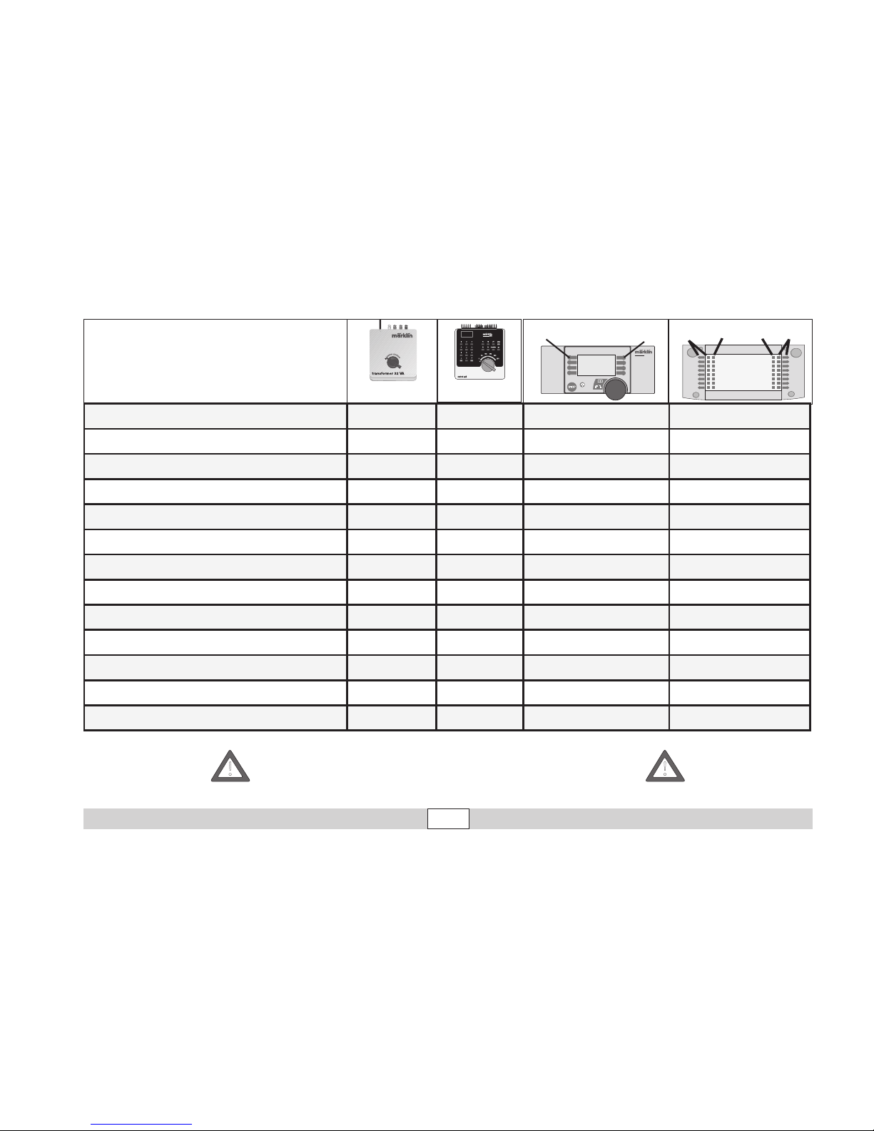
Controllable Functions
6647
6021
STOP
mobile station
systems
1
5
60652
central
station
60212
f0
f0f8
f8
Headlights/Engineer‘s cab lighting
Always on function + off
Headlight button
Button f0 with symbol
Interior lights
f1 Button 1 with symbol Button f1 with symbol
Sound: Operating sounds
— f2 Button 2 with symbol Button f2 with symbol
Sound effect: Long Horn
— f3 Button 6 with symbol Button f3 with symbol
Low speed switching range (only with ABV)
— f4 Button 4 with symbol Button f4 with symbol
Sound effect: Station announcements
— — Button 3 with symbol Button f5 with symbol
Sound effect: Conductor whistle
— — Button 8 with symbol Button f6 with symbol
Sound effect: Short Horn
— — Button 5 with symbol Button f7 with symbol
Sound effect: Opening doors
— — Button 7 with symbol Button f8 with symbol
Sound effect: Squealing brakes off
— — — Button f9 with symbol
Sound effect: Rail joints
— — — Button f10 with symbol
Sound effect: Air pump
— — — Button f11 with symbol
Sound effect: Lubrication pump
— — — Button f12 with symbol
Perfect operation of the locomotive with the functions „function“ and f1 through f4 is only possible with the 6021 Control
Unit. The full range of functions on the locomotive is only
available with the 60212 Central Station
!
!
Page 14

14
Fonctionnement
Cette locomotive possède un équipement électronique
pour conduite multitrain:
• Au choix, exploitation conventionnelle avec courant continu
(max ± 18 volts =), courant alternatif (Transformer 32 VA), ex
ploitation avec Märklin Delta (uniquement Delta Station 6607),
Märklin Digital (uniquement Control Unit) ou Märklin
Systems
(Mobile Station ou Central Station). Une exploitation
avec
d’autres systèmes d’exploitation (courant à largeur d’impulsion
variable, Central Control 1, etc.) n’est pas possible.
• Le mode d’exploitation est automatiquement détecté.
• Adresses disponibles: 01 – 80.
Adresse encodée en usine: 37
• Technologie Mfx pour Mobile Station / Central Station.
Nom en codee en usine: SVT 137
• Temporisation d’accélération réglable (ABV).
• Temporisation de freinage réglable (ABV).
• Vitesse maximale réglable
• Volume des bruitages réglable
•
Réglage des paramètres de la loco électroniquement à l’aide
de la Control Unit, de la Mobile Station ou de la Central Station.
• Bruiteur électronique intégré, utilisable uniquement lors d’exploitation avec la Control Unit ou Märklin Systems. Bruitages
complémentaires commutables.
• Le modèle réduit est conçu pour rouler sur des voies Märklin 1. Le
faire rouler sur des voies d’autres systèmes comporte des risques
.
• Rayon minimal d’inscription en courbe: 1020 mm.
• A l’exception des feux de signalisation les fonctions sont
désactivées en mode d’exploitation courant continu, courant
alternatif et Märklin Delta.
Les travaux d‘entretien occasionnels à effectuer en exploitation ormale sont décrits plus loin. Pour toute réparation ou remplacement
de pièces, adressez-vous à votre détaillant-spécialiste Märklin.
Tout recours à une garantie commerciale ou contractuelle ou à une demande de
dommages-intérêt est exclu si des pièces non autorisées par Märklin sont inté
grées dans les produits Märklin et / ou si les produits Märklin sont transformés
et que les pièces d’autres fabricants montées ou la transformation constituent
la cause des défauts et / ou dommages apparus. C’est à la personne et / ou la
société responsable du montage / de la transformation ou au client qu’incombe
la charge de prouver que le montage des pièces d’autres fabricants sur des
produits Märklin ou la transformation des produits Märklin n’est pas à l’origine
des défauts et ou dommages apparus.
Remarques importantes sur la sécurité
•
La locomotive ne peut être mise en service qu’avec un
système d’exploitation adéquat (Märklin courant alternatif transformateur 6647, Märklin Delta, Märklin Digital ou Märklin
Systems). N’utilisez en aucun cas de transformateurs pour
une tension à l’entrée de 220 V - 110 V pour les Etats-Unis.
• La locomotive ne peut être alimentée en courant que par
une seule source de courant.
•
Pour l’exploitation de la rame automotrice en mode conventionnel, la voie de raccordement doit être déparasitée. A cet effet,
utiliser le set de déparasitage réf. 104770. Le set de déparasi
-
tage ne convient pas pour l’exploitation en mode numérique.
• Veuillez impérativement respecter les remarques sur la
sécurité décrites dans le mode d’emploi en ce qui concerne le système d’exploitation.
Page 15
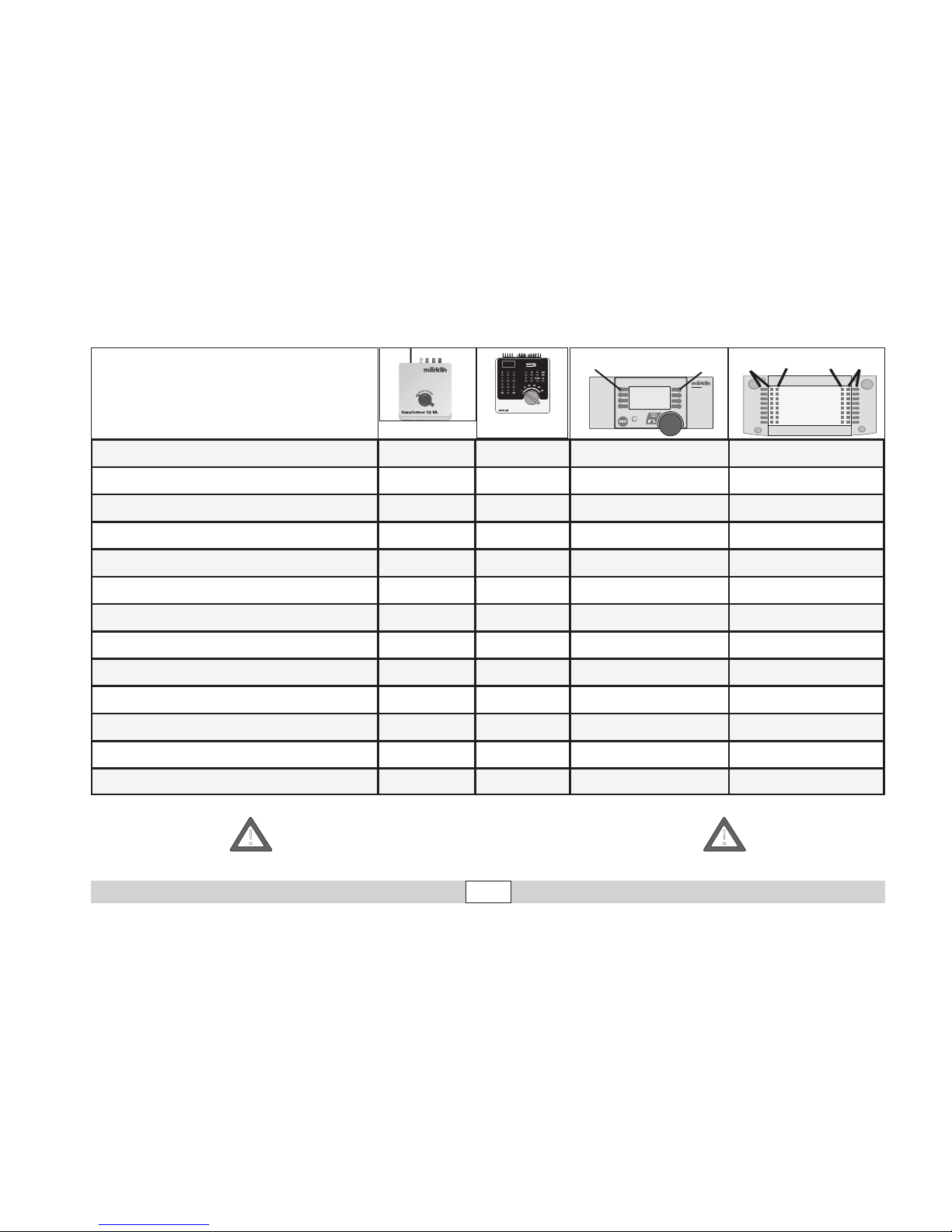
15
Fonctions commutables
6647
6021
STOP
mobile station
systems
1
5
central
station
60212
f0
f0f8
f8
Fanal / Eclairage de la cabine de conduite
Activé function + off Touche éclairage Touche f0 avec symbol
Eclairage intérieur
f1 Touche 1 avec symbol Touche f1 avec symbol
Bruitage : Bruit d’exploitation
— f2 Touche 2 avec symbol Touche f2 avec symbol
Bruitage : Trompe long
— f3 Touche 6 avec symbol Touche f3 avec symbol
Vitesse de manœuvre (Acc./Fr)
— f4 Touche 4 avec symbol Touche f4 avec symbol
Bruitage : Annonce en gare
— — Touche 3 avec symbol Touche f5 avec symbol
Bruitage : Sifflet Contrôleur
— — Touche 8 avec symbol Touche f6 avec symbol
Bruitage : Trompe court
— — Touche 5 avec symbol Touche f7 avec symbol
Bruitage : Ouvrir les portes
— — Touche 7 avec symbol Touche f8 avec symbol
Bruitage : Grincement de freins désactivé
— — — Touche f9 avec symbol
Bruitage : Joints de rail
— — — Touche f10 avec symbol
Bruitage : Compresseur
— — — Touche f11 avec symbol
Bruitage : Distributeur d‘huile
— — — Touche f12 avec symbol
Une exploitation parfaite de la rame automotrice avec les
fonctions « function » et f1 à f4 est possible uniquement avec
la Control Unit 6021 ; l’intégralité des fonctions est disponible
uniquement avec la Central Station 60212.
!
!
60652
Page 16

16
Werking
Deze loc met ingebouwde digitaalelektronica biedt u:
•
Naar keuze conventioneel bedrijf (wisselstroom met de
Transformer 32 VA of gelijkstroom [max +/– 18 Volt=] ), bedrijf
met Märklin Delta (alleen het Delta Station 6607), Märklin
Digital (Control Unit) of het Märklin Systems (Mobile Station
of Central Station). Het bedrijf met rijregelaars van andere sy
stemen (bijv. impulsbreedte sturing, gebruik van de CentralControl 1 (6030) of een dergelijk systeem) is niet mogelijk.
• Het bedrijfssysteem wordt automatisch herkend.
• Instelbare adressen: 01-80. Vanaf de fabriek:
37.
• Mfx-technologie voor het Mobile Station / Central Station.
Naam af de fabriek: SVT 137
•
Instelbare optrekvertraging.
• Instelbare afremvertraging.
• Instelbare maximumsnelheid.
• Volume van de geluiden instelbaar
• Elektronische instelling van de locomotiefparameters via
de Control Unit, Mobile Station of Central Station.
• Ingebouwde geluidselektronica, alleen bruikbaar in het
bedrijf met de Control Unit of Märklin Systems. Extra
schakelbare geluiden.
• Het model is ontwikkeld voor het gebruik op het Märklin
Spoor 1 railsysteem. Het gebruik op een ander railsysteem geschied op eigen risico.
• Berijdbare minimumradius: 1020 mm.
• Op de frontverlichting na zijn de functies in het bedrijf met
gelijkstroom, wisselstroom en Märklin Delta uitgeschakeld.
De in het normale bedrijf voorkomende onderhoudswerkzaamheden zijn verderop beschreven. Voor reparatie of onderdelen kunt u
zich tot uw Märklin winkelier wenden.
Elke aanspraak op garantie en schadevergoeding is uitgesloten, wanneer in
Märklin-producten niet door Märklin vrijgegeven vreemde onderdelen inge
bouwd en / of Märklin-producten omgebouwd worden en de ingebouwde
vreemde onderdelen resp. de ombouw oorzaak van nadien opgetreden
defecten en / of schade was. De aantoonplicht en de bewijslijst daaromtrent,
dat de inbouw van vreemde onderdelen in Märklin-producten of de ombouw
van Märklin-producten niet de oorzaak van opgetreden defecten en / of
schade is geweest, berust bij de voor de inbouw en/of ombouw verantwoordelijke persoon en / of firma danwel bij de klant.
Veiligheidsvoorschriften
• De loc mag alleen met een daarvoor bestemd bedrjfssy-
steem (Märklin wisselstroom transformator 6647, Märklin
Delta, Märklin digitaal of Märklin Systems) gebruikt worden.In geen geval transformatoren met een ingangsspanning van 220 V - voor USA 110 V - gebruiken.
• De loc mag niet vanuit meer dan één stroomvoorziening
-
gelijktijdig gevoed worden.
• Voor het conventionele bedrijf met de het treinstel dient
de aansluitrail te worden ontstoort. Hiervoor dient men de
ontstoor-set 104770 te gebruiken.Voor het digitale bedrijf
is deze ontstoor-set niet geschikt.
• Lees ook aandachtig de veiligheidsvoorschriften in de
gebruiksaanwijzing van uw bedrijfssysteem.
Page 17
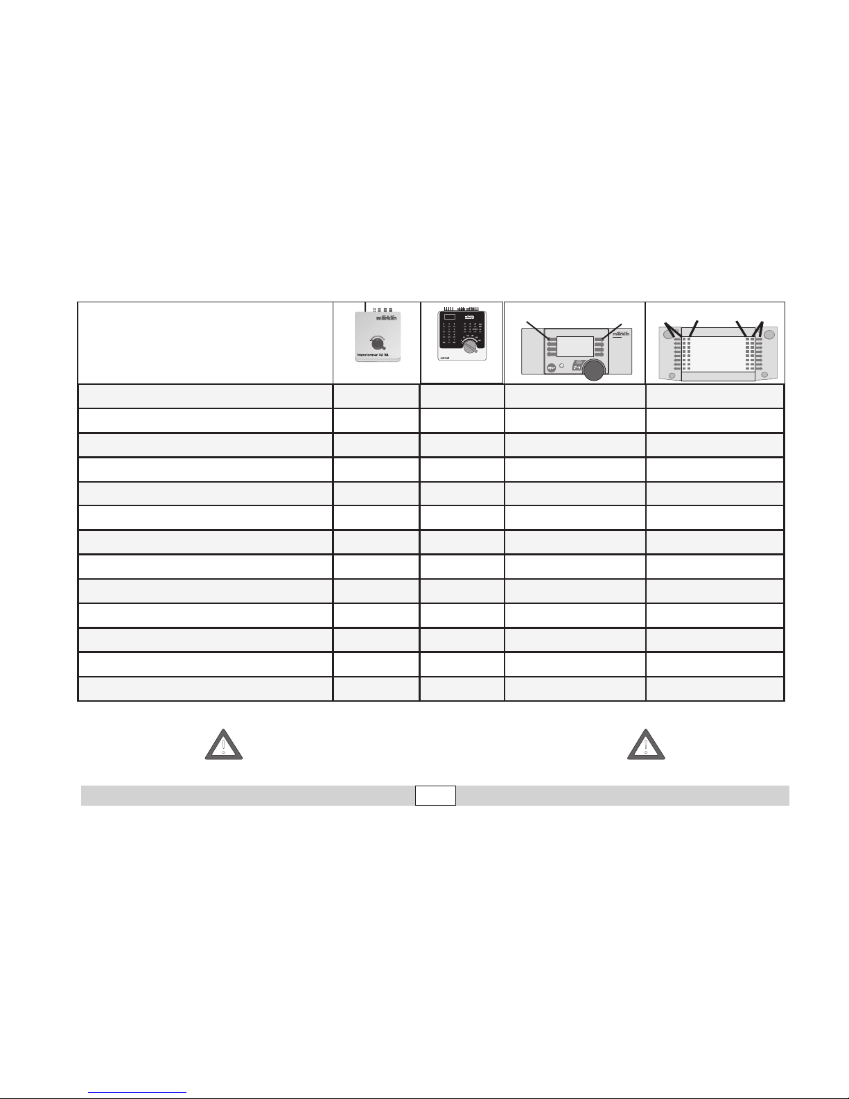
17
Schakelbare functies
6647
6021
STOP
mobile station
systems
1
5
60652
central
station
60212
f0
f0f8
f8
Frontverlichting / Cabineverlichting
Continu aan function + off Verlichtingstoets Toets f0 met symbool
Binnenverlichting
— f1 Toets 1 met symbool Toets f1 met symbool
Geluid: bedrijfsgeluiden
— f2 Toets 2 met symbool Toets f2 met symbool
Geluid: signaalhoorn lang
— f3 Toets 6 met symbool Toets f3 met symbool
Rangeerstand (alleen optrek- afremvertraging)
— f4 Toets 4 met symbool Toets f4 met symbool
Geluid: stationsomroep
— — Toets 3 met symbool Toets f5 met symbool
Geluid: conducteurfluit
— — Toets 8 met symbool Toets f6 met symbool
Geluid: signaalhoorn kort
— — Toets 5 met symbool Toets f7 met symbool
Geluid: Deuren openen
— — Toets 7 met symbool Toets f8 met symbool
Geluid: piepende remmen uit
— — — Toets f9 met symbool
Geluid: raillassen
— — — Toets f10 met symbool
Geluid: luchtpomp
— — — Toets f11 met symbool
Geluid: smeerpomp
— — — Toets f12 met symbool
Een storingvrij rijbedrijf van deze trein met de functies f1-f4 is
alleen mogelijk met de Control Unit 6021, de volledige functieomvang alleen met het Central Station 60212.
!
!
Page 18

18
Anschluss der Gleisanlage
Um Spannungsverluste auf der
Anlage zu vermeiden ist
immer auf gutes Zusammenpassen der Schienenverbindungslaschen zu achten.
Alle 2 bis 3 m ist eine neue
Stromeinspeisung über die
Anschlussklemmen 5654 empfehlenswert.
Befahren von Steigungen
Im Gegensatz zum Vorbild kön
nen mit einer Modellbahn auch
größere Steigungen befahren
werden. Im Normalfall sollte
eine Steigung bei maximal 3
Prozent liegen. Im Extrem
fall sind bei entsprechend
eingeschränkter Zugleistung
maximal 5 Prozent möglich.
Der Anfang und das Ende der
Steigung sind auf jeden Fall
auszurunden.
Der Unterschied in der Steigung zwischen zwei mindestens 300 mm langen Gleisstücken darf maximal 1 bis 1,5
Prozent betragen.
Connections between the
track layout and the transformer
Rail joiners must fit well on the
rails of the track to which they
are joined to avoid voltage drop
on the layout. We recommend
that you install feeder wires
every 2 to 3 meters (7 to 10
feet) using the 5654 feeder
clips.
Operating the locomotive on
grades
In contrast to the prototype
a
locomotive on a model railroad
can operate up steeper grades.
As a general rule a grade
should be no steeper than 3%.
In extreme situations a maxi
mum grade of 5% is permissible, keeping in mind that the
locomotive’s tractive effort will
be less. The beginning and the
end of the grade must always
work gradually up to maximum grade for the route. The
maximum allowable difference
in grade between two track
sections, each with a minimum
length of 300 mm (11-3/4“) is 1
to 1.5 percent.
Connexion des voies
ferrées
Pour éviter des pertes de
potentiel sur l’installation, il faut
veiller à ce que les éclisses de
liaison des rails soient toujours
parfaitement adaptées. Une
nouvelle alimentation électrique est conseillée tous les
2 à 3 m au moyen des griffes
d’alimentation 5654.
Franchissement des côtes
Contrairement à l’original,
la maquette est également en
mesure de franchir des côtes
assez importantes. En temps
normal, une côte devrait étre
de l’ordre de 3% maximum.
A l’extrême limite, 5% sont
envisageables avec une
puissance du train réduite en
consequence. Le début et la fin
de la côte doivent en tous cas
étre arrondis.
La différence de pente
entre deux éléments de voie
d’au moins 300 mm de longueur doit étre de 1 à 1,5%
maximum.
Aansluiting van de sporen
Om spanningsverlies op de
modelbaan te voorkomen
moeten de raillassen altijd goed
op elkaar aansluiten. Om de 2 à
3 meter moet de voeding opnieuw op de rails gezet worden.
Daarbij zijn de aansluitklemmen
5654 aan te raden.
Berijden van hellingen
In tegenstelling tot het grote
voorbeeld kunnen met een
modelbaan ook grotere hellingen bereden worden. Normaal
moet een helling maximaal
3 procent zijn.
In extreme
gevallen is maximaal 5 procent
mogelijk, maar
dan moet rekening gehouden worden met een
evenredig verlies aan vermogen. Het begin en het einde
van de helling moeten altijd
gerond worden.
Het verschil in de helling
tussen twee tenminste 300 mm
lange railstukken mag maximaal 1 à 1,5 procent bedragen.
Page 19

19
Lokparameter einstellen mit
der Control Unit
1.
Voraussetzung: Aufbau wie
Grafik S. 20. Nur die zu verändernde Lok ist auf dem Gleis.
2. „Stop“- und „Go“-Taste
gleichzeitig drücken, bis „99“
in der Anzeige aufblinkt.
3. „Stop“-Taste drücken.
4. Lokadresse „80“ eingeben.
5.
Umschaltbefehl am Fahrregler halten.
Während des Hal-
tens die „Go“-Taste drücken.
6. Licht der Lok blinkt lang
sam. Wenn nicht, ab Schritt
2 wiederholen.
7.
Registernummer für den zu
ändernden Para-meter eingeben (=> Liste auf Seite 22).
8.
Fahrtrichtungswechsel betätigen.
9. Licht blinkt schnell
10. Neuen Wert eingeben (=>
Liste auf Seite 22).
11.
Fahrtrichtungswechsel betätigen.
12. Licht blinkt langsam (Ausnahme Werkreset)
13.
Nächste Parametereinstellung
ab 6. oder beenden mit 14.
14. Vorgang beenden mit
Drücken der „Stop“-Taste.
Anschließend Drücken der
„Go“-Taste.
Setting Locomotive Parameters with
the Control Unit
1.
Requirement: Setup as in diagram
on page 20. Only the locomotive
to be changed can be on the
track.
2. Press the “Stop” and “Go” at the same
time until “99” blinks in the display.
3. Press the “Stop” button.
4.
Enter the locomotive address „80“
.
5. Hold the control knob in the
reverse direction area. While
holding the control knob here,
press the „Go“ button.
6. The headlights on the locomotive will blink slowly. If they don‘t,
repeat Step 2.
7. Enter the register number for the
parameter to be changed (=>
List on page 22).
8.
Active the change of direction
.
9.
The headlights will blink rapidly.
10.Enter the new value (=>List on
page 22).
11.
Active the change of direction.
12.
The headlights will blink slowly
(exception: factory reset)
13.Enter the next parameter setting from
6 or end with 14.
14.End the process by pressing the
„Stop“ button. Then press the
„Go“ button.
Réglage des paramètres de la
loco avec la
Control Unit
1. Condition: Montage comme sur
illustration en page 20. Seule la
loco à modifier peut se trouver sur
la voie.
2. Pressez simultanément les touches
„Stop“ et „Go“ jusqu’à ce que le
nombre „99“ clignote sur l’écran.
3. Pressez la touche „Stop“.
4. Introduisez l’adresse de loco „80“.
5.
Maintenir l’ordre de commutation sur
le régulateur de marche. Durant le
maintien, appuyer sur la touche „Go“.
6. Les feux de la locomotive clignotent lentement. Dans le cas contraire, renouveler l’opération à partir
de l’étape 2.
7. Indiquer le numéro ’enregistrement
pour le paramètre à modifier (=>
liste page 22).
8.
Activer l’inversion du sens de marche.
9. Les feux clignotent rapidement.
10.
Entrer la nouvelle valeur (=> liste page22).
11. Activer l’inversion du sens de marche.
12. Les feux clignotent lentement
(exception : réinitialisation aux
valeurs d’usine)
13.
Définition de paramètres suivante à par-
tir du point 6 ou terminer par le point 14.
14. Terminez le processus en pressant
la touche „Stop“. Ensuite, pressez
la touche „Go“.
Locparameters instellen met
de Control Unit
1. Voorwaarde: opbouw zoals tekening op pagina 20. Alleen de loc die
gewijzigd moet worden op de rails.
2. ”Stop”- en ”Go”-toets gelijktijdig
indrukken tot ”99” in het display
oplicht.
3. ”Stop”-toets indrukken.
4. Het adres „80“ invoeren.
5. Omschakelcommando met de
rijregelaar vasthouden. Tijdens
het vasthouden de toets “Go”
indrukken.
6. De verlichting van de loc knippert langzaam. Indien dit niet het
geval is, vanaf stap 2 opnieuw
beginnen.
7. Het registernummer van de te
wijzigen parameter invoeren
(=> lijst op pagina 22).
8. Omschakelcommando geven.
9. Verlichting gaat snel knipperen.
10. Nieuwe waarde invoeren (=>
lijst op pagina 22).
11. Omschakelcommando geven.
12. Verlichting knippert langzaam
(uitgezonderd bij decoder reset)
13. Volgende parameterinstelling
of beëindigen met 14
14. Sessie beëindigen door het
indrukken van de toets “Stop”.
Aansluitend de toets “Go”
indrukken.
Page 20
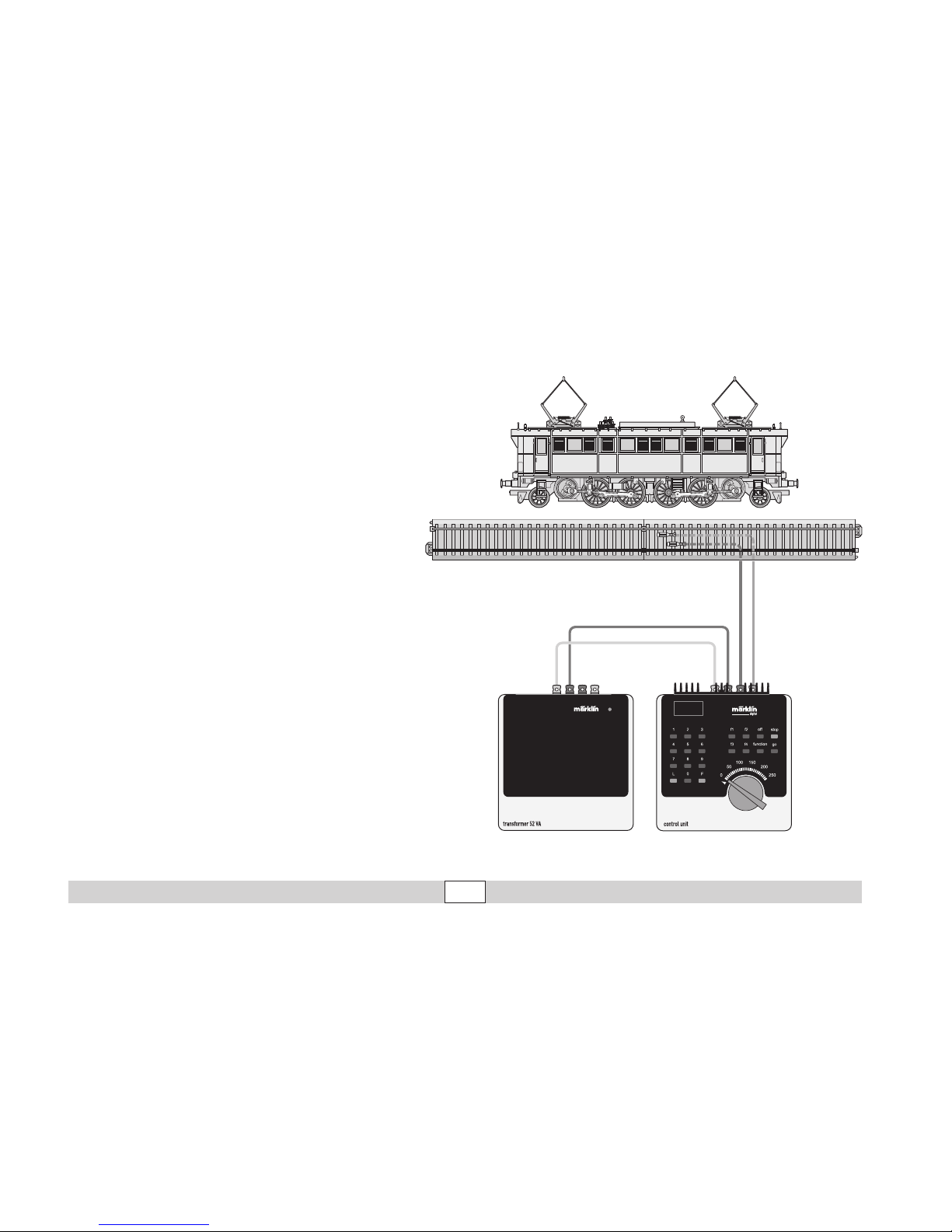
20
Lokparameter mit Control Unit ändern.
Changing Locomotive Parameters with the Control Unit.
Modification des paramètres avec la Control Unit.
Locparameter met de Control Unit.
Modificar los parámetros de la locomotora con el Control Unit.
Modifica dei parametri della locomotiva con la Control Unit.
Lokparametrar ändras med Control Unit.
Ændring af lokomotivparametre med Control Unit.
Page 21
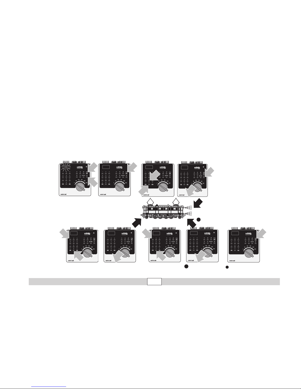
21
1
80
1
Lokparameter ändern mit der Control Unit 6021.
Changing Locomotive Parameters with the 6021 Control Unit.
Modification des paramètres de la locomotive avec la Control Unit 6021.
Locparameter wijzigen met de Control Unit.
Modificar los parámetros de la locomotora con el Control Unit 6021.
Modifica dei parametri della locomotiva con la Control Unit 6021.
Lokparametrar ändras med Control Unit 6021.
Ændring af lokomotivparametre med Control Unit 6021.
1
1
99
1
2
80
2
1
01
01
1
1
2
10
10
1
11
14
12
Page 22

22
Parameter • Parameter • Paramètre • Parameter •
Parámetro • Parametro • Parameter • Parameter
Register • Register •
Registre • Register •
Registro • Registro •
Register • Register
Wert • Value • Valeur •
Waarde • Valor • Valore •
Värde • Værdi
Adresse • Address • Adresse • Adres • Código • Indrizzo •
Adress • Adresse
01 01 - 80
Anfahrverzögerung • Acceleration delay • Temoprisation accélération • Optrekvertraging • Regulación arranque • Ritardo di
avviamento • Igångsättningsreglering • Opstartregulierung
03 01 - 63
Bremsverzögerung • Braking delay • Temporisation de freinage •
Afremvertraging • Frenado lento • Ritardo di frentura • Broms
-
fördröjning • Bremseforsinkelse
04 01 - 63
Höchstgeschwindigkeit • Maximum speed •
Vitesse maximale • Maximumsneilheid • Velocidad máxima •
Velocità massima • Toppfart • Maksimalhastighed
05 01 - 63
Rückstellen auf Serienwerte • Reset to series value • Remettre aux valeurs de série • Terugzetten naar serie-instellingen •
Restablecer los valores de serie • Pipristinare sui valori di serie •
Återställa till standardvärden • Tibagestil til serieværdien
08 08
Lautstärke • Volume • Volume haut-parleur • Volume • Volumen
del sonido Intensit à sonara • Ljudstyrka • Lydstyrke
63 01 - 63
Page 23

23
Betrieb mit Mobile Station / Central Station
• Lok aufgleisen. Die Lok meldet sich selbsttätig in der
Lokliste an.
• Keine Rückmeldung der Lok, wenn:
bei Mobile Station der Geschwindigkeitsbalken blinkt
bei Central Station das mfx-Symbol unterstrichen ist
• Lok abmelden:
1. Lok vom Gleis entfernen.
2. Lokeintrag löschen.
Eine Adressänderung ist nicht notwendig.
Lokparameter mit der Mobile Station / Central Station ändern
1. Lok aus der Lokliste auswählen.
2. Zum Untermenü „LOKÄNDERN“ wechseln.
3. Zum Untermenü „VMAX“ (Höchstgeschwindigkeit),
„ACC“ (Beschleunigung), „DEC“ (Bremsen),
„VOL“ (Lautstärke) oder
„RESET“ (Decoder auf Werkeinstellung zurück) wechseln.
4. Neuen Wert eingeben und übernehmen.
Beachten Sie die Hinweise in der Anleitung zur Mobile Station /
Central Station.
Operation with the Mobile Station / Central Station
• Set the locomotive on the track. The locomotive automatically registers itself in the locomotive list.
• The locomotive will not communicate back to the control
ler when:
the speed bar on the Mobile Station blinks.
the mfx symbol has a line beneath it on the Central Station.
• Taking the locomotive out of the locomotive list:
1. Remove the locomotive from the track.
2. Delete the locomotive entry.
It is not necessary to change the address.
Changing Locomotive Parameters with the
Mobile Station / Central Station
1. Select the locomotive from the locomotive list.
2. Change to the submenu “EDIT LOC”.
3. Go to the submenu „VMAX“ (maximum speed),
„ACC“ (acceleration), „DEC“ (brakes),
„VOL“ (volume) or
„RESET“ (resetting the decoder to factory default settings)
.
4. Enter the new value and accept it into the system.
Please note the information in the instructions for the Mobile Station / Central Station.
Page 24

24
Exploitation avec Mobile Station / Central Station
• Enrailler la locomotive. La locomotive signale automatiquement sa présence dans la liste des locos.
• Pas de rétrosignalisation de la locomotive lorsque :
- la barre de vitesse clignote pour Mobile Station
- le symbole mfx est souligné pour Central Station
• Appeler loco:
1. Enlever loco de la voie.
2. Effacer entrée loco.
Une modification de l’adresse n’est pas nécessaire.
Modification des paramètres de la loco avec la Mobile Station/
Central Station
1. Sélectionnez la loco dans la liste.
2. Allez au sous-menu „MODIF LOC“.
3. Ouvrir le sous-menu « VMAX » (vitesse maximale),
« ACC » (accélération), « DEC » (freinage),
« VOL » (volume) ou
« RESET » (réinitialisation du décodeur aux valeurs d’usine).
4. Entrez la nouvelle valeur et acceptez.
Respectez les remarques mentionnées dans l’instruction accompagnant la Mobile Station / Central Station.
Bedrijf met Mobile Station / Central Station
• Loc op de rails plaatsen. De loc meldt zichzelf aan in de
loclijst.
• Geen terugmelding van de loc als:
bij het Mobile Station de snelheidsbalk knippert
bij het Central Station het mfx-symbool onderstreept is
• Loc afmelden:
1. loc van de rails nemen
2. loc invoer wissen.
Het wijzigen van het adres is niet nodig.
Locparameter wijzigen met het Mobile Station/Central Station
1. Loc uit de loclijst kiezen.
2. Ga naar het nevenmenu ”WIJZIG LOC”.
3. Naar het nevenmenu “VMAX” (maximumsnelheid)
“ACC” (optrekken), “DEC” (afremmen),
“VOL” (volume) of
“RESET” (decoder terugzetten naar fabrieksinstelling)
omschakelen.
4. Nieuwe waarde invoeren en overnemen.
Lees ook de opmerkingen in de gebruiksaanwijzing van het Mobile
Station / Central Station.
Page 25

25
Pflegehinweis
Diese Lok kann auch im
Außenbereich eingesetzt
werden. Ein Betrieb bei
schlechten Witterungsbedingungen (Schnee oder
Regen) wird nicht empfohlen.
Antrieb und Elektronik
sind gegen Spritzwasser
geschützt. Wasserdurchfahrten sind nicht möglich.
Es wird empfohlen, das
Modell nach dem Betrieb
im Außenbereich auf Verschmutzung zu prüfen und
gegebenenfalls trocken mit
Staubtuch oder Pinsel zu
reinigen. Nie die Lok unter
fließendem Wasser reinigen.
Hinweis: Reinigungsmittel können die Farbgebung
oder die Beschriftung der
Lok angreifen und beschä
-
digen.
Remarque sur
l’entretien
Cette locomotive peut
également être mise en
service à l’air libre. Une utilisation par mauvais temps
(neige ou pluie) n’est pas
recommandée.
Le moteur et l’électronique sont protégés contre
les projections d’eau. Des
trajets dans l’eau ne sont
pas possibles.
Il est recommandé de
vérifier l’encrassement du
modèle après une utilisation à l’extérieur et, le cas
échéant, de nettoyer le
modèle à l’aide d’un chiffon
doux ou un pinceau. Ne
jamais nettoyer le modèle
au jet d’eau.
Attention: Certains solvants et produits d’entretien
peuvent altérer le marquage
et la peinture du modèle.
Tips For The Care Of
Your Locomotive
This locomotive can also
be used outdoors. We do
not recommend running the
locomotive in bad weather
(snow or rain).
The mechanism and the
electronic circuit are protected against spraying water.
The locomotive cannot be
run through water.
We recommend that you
check the locomotive over
after running in outdoors
and that you dry it with
a cloth or clean in with a
brush if necessary. Never
clean the locomotive with
running water.
Important: Cleaning fluids can attack the finish and
lettering for the locomotive
and damage them.
Opmerkingen voor het
onderhoud
Deze loc kan ook buiten
gebruikt worden. Het
gebruik bij slecht weer
(sneeuw of regen) is niet
aan te raden.
Aandrijving en elektronica zijn weliswaar afgeschermd tegen spatwater
maar rijden door het water
is niet mogelijk.
Het is aan te bevelen het
model na het gebruik buiten
te controleren op vuil en dit
eventueel droog te verwijderen met een stofdoek of
een zachte kwast. Nooit de
loc onder stromend water
reinigen.
Opmerking: reinigingsmiddelen kunnen de lak en
de opschriften op de loc
aantasten en beschadigen.
Page 26
26
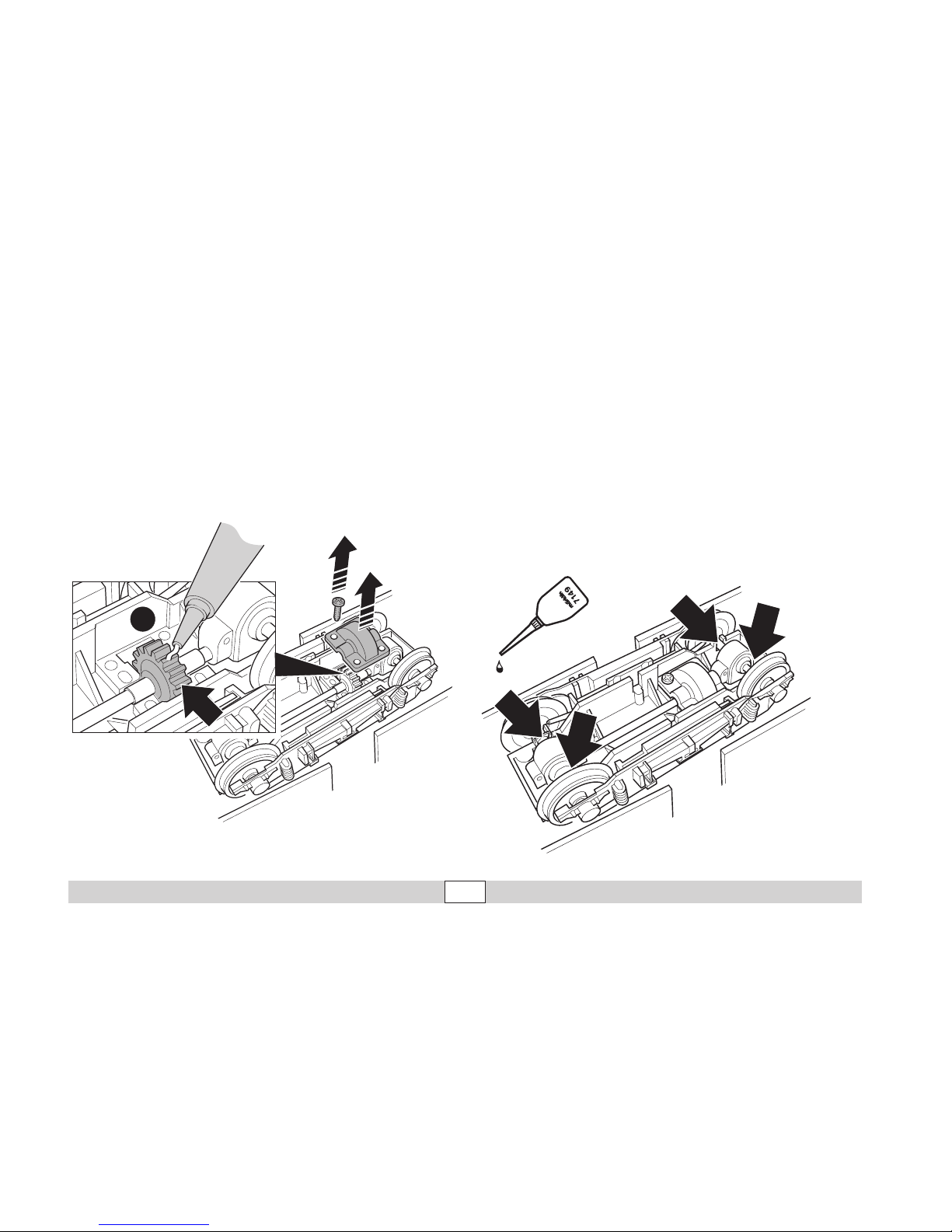
Schmierung nach 40 Betriebsstunden. Nur sparsam ölen, max.
1 Tropfen je Achslager.
Lubrication after 40 hours of operation. Oil very sparingly, ma
-
ximum of 1 drop per axle bearing.
Graissage après 40 heures d’exploitation. Utiliser très peu
d’huile, maximum 1 goutte par boîte d’essieu.
Smeren na 40 bedrijfsuren. Slechts spaarzaam oliën, max 1
druppel per aslager
Bitte nur Spezialfett verwenden! Kein Öl! Kein Haushaltsfett!
Use only special grease!
No oil! No domestic grease!
N’utiliser que de la graisse spéciale! Ne pas utiliser
d’huile! Ne pas utiliser de graisse ménagère!
Uitsluitend speciaal vet gebruiken! Geen olie! Geen
huishoudvet!
1.
2.
4x
Trix
3.
Page 27
27
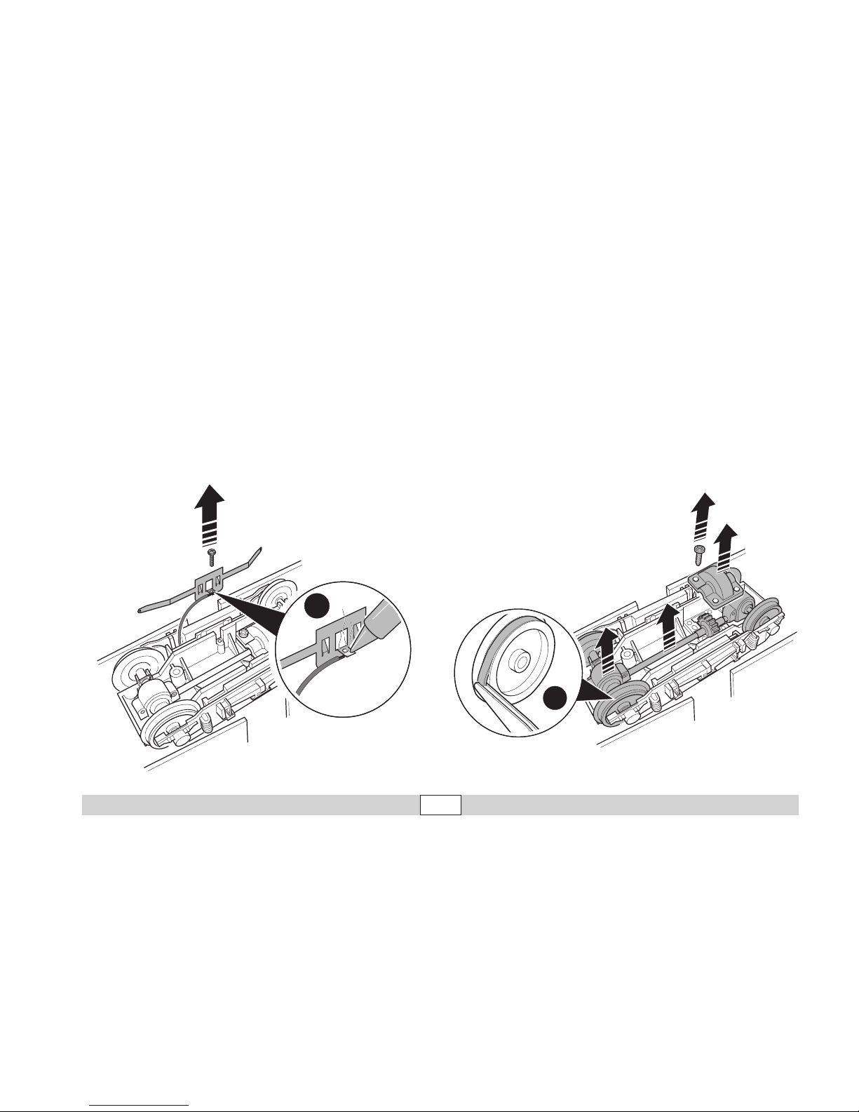
Zum Radschleiferwechsel markierte Schrauben lösen, Kabel
ablöten, neuen Radschleifer einsetzen, Kabel anlöten.
In order to replace the electrical wheel pickup, loosen the
screws indicated, unsolder the wire, install the new electrical
wheel pickup, and re-solder the wire.
Pour changer les frotteurs de roue, dévisser les vis marquées,
dessouder le câble, mettre les nouveaux frotteurs en place,
souder les câbles.
Voor het vervangen van de wielcontacten de gemerkte schroe
ven losdraaien, draad los solderen, nieuwe wielsleper plaatsen,
draad vast solderen.
1.
2.
1.
2.
4x
3.
3.
4.
Zum Haftreifenwechsel markierte Schrauben lösen, Antriebseinheit herausnehmen.
Loosen the screws indicated and remove the mechanism in
order to replace traction tires.
Pour changer les bandages d’adhérence, dévisser les vis mar
-
quées ; retirer l’unité motrice.
Voor het vervangen van de antislipbanden de gemerkte schroe
-
ven losdraaien, aandrijfeenheid er uit nemen.
Page 28

This device complies with Part 15 of the FCC Rules.
Operation is subject to the following two conditions:
(1) This device may not cause harmful interference, and
(2) this device must accept any interference received, including
interference that may cause undesired operation.
Gebr. Märklin & Cie. GmbH
Postfach 8 60
D-73008 Göppingen
www.maerklin.com
Änderungen vorbehalten
© by Gebr. Märklin & Cie GmbH
101560 01 07 Ni Ef
 Loading...