

Page 1

Modell der Baureihe 144
54293
Page 2

Informationen zum Vorbild
Die Wirtschaftskrise Ende der 20er-Jahre im 20. Jahrhundert führte zu einem vorübergehenden Erlahmen der Aktivi
täten der Deutschen Reichsbahn bei der weiteren Strecken
elektrifizierung. Gleichzeitig wurde auch die Beschaffung
neuer Elektrolokomotiven unterbrochen. Diese Lücke füllten
die drei Lokomotivfabriken Bergmann-Elektrizitäts-Werke
AG, Maffei-Schwartzkopf-Werke GmbH und SiemensSchuckert-Werke AG durch die Eigenentwicklung
einer neuer E-Lok. Jede Fabrik entwickelte ihre
eigene Lösung, die von der Deutschen Reichsbahn unter
der Baureihe E 44 (SSW-Version), E 44
E 4420 (BEW-Version) eingereiht wurde.
5
(MSW-Version) und
Einer der entscheidenden Unterschiede zu früheren E-LokKonstruktionen ist die Verwendung zweier Drehgestelle
ohne Vorlaufachsen. Damit stellt diese Lok den Urahn
moderner Fahrwerk-Konstruktionen dar. Mit einer Höchst
-
geschwindigkeit von 90 km/h und einer Leistung von bis
-
zu 2200 kW konnte diese gelungene Konstruktion den
Betriebsanforderungen bis in die Epoche IV hinein gerecht
werden. Die E 44 wurde bei der Deutschen Bundesbahn
1982 ausgemustert. Für die E 44 bei der DR war 1992 das
Betriebs-Ende gekommen. Eine knappe Hand voll
Maschinen sind bis heute als Museumslokomotiven
erhalten geblieben.
-
20
Während die E 44
nur in zwei kleinen Baulosen mit jeweils 4 Stück hergestellt
wurde, war die E 44 von Siemens die eindeutig erfolgreichste Entwicklung mit einer Anzahl von über 180 Stück.
Dabei wurden die letzten Lokomotiven dieser Baureihe
sogar noch von der DB beschafft, wodurch sich bei dieser
Lok eine Gesamtbauzeit von ca. 20 Jahre ergibt.
Eingesetzt wurden diese Lokomotiven schwerpunktmäßig
auf der ab 1933 elektrifizierten Strecke Stuttgart-Augsburg.
Von den 174 vor dem Krieg hergestellten Versionen blieben
45 Stück bei der Deutschen Reichsbahn und wurden dort
später als Baureihe 244 bezeichnet. Die restlichen Modelle
wurden von der Deutschen Bundesbahn übernommen und
ab 1968 als Baureihe 144 geführt. Einige dieser Fahrzeuge
wurde für den Wendezugbetrieb technisch ergänzt.
ein Einzelstück blieb und die E 44
5
2
Vorbild • Prototype • Exploitation dans le réel • Grootbedrijf
Page 3
Information about the prototype
The economic crisis at the end of the 1920s in the 20th
century lead to an ongoing decline in activity on the
German State Railroad for further route electrification. At
the same time the purchase of new electric locomotives
was also put on hold. This gap was filled by the three
locomotive builders Bergmann-Elektrizitäts-Werke AG,
Maffei-Schwartzkopf-Werke GmbH and SiemensSchuckert-Werke AG by the development of a new electric
locomotive. Each builder developed his own solution that
was desig-nated by the German State Railroad as the class
E 44 (SSW version), E 445 (MSW version) and E 4420 (BEW
version).
20
While the E 44
built in only two small groups of 4 units each, the E 44 from
Siemens was clearly the most successful development with
a quantity of over 180 units. The last of the locomotives in
this class were even purchased by the DB, resulting in a total
period of manufacture of about 20 years for this locomotive.
These locomotives were used mostly on the Stuttgart –
Augsburg route that was electrified starting in 1933. Of the
174 units built before the war, 45 ended up with the German
State Railroad (East Germany) and were later designated
there as the class 244. The remaining units were acquired
by the German Federal Railroad and were operated as the
class 144 starting in 1968. A number of these units were
modified technically for push/pull operations.
remained a one-off unit and the E 445 was
One of the critical differences compared to earlier electric
locomotive building was the use of two trucks without pilot
trucks. This locomotive thereby represents the beginnings
of modern locomotive framework designs. With a maximum
speed of 90 km/h (56 mph) and up to 2,200 kilowatts
(2,950 hp), this successful design was able to fulfill opera
ting requirements well into Era IV. The E 44 was retired by
the German Federal Railroad in 1982. For the E 44 units on
the DR, 1992 was the last year of operation. Just a handful
of these units are still in existence as museum locomotives.
-
Vorbild • Prototype • Exploitation dans le réel • Grootbedrijf
3
Page 4

Informations concernant la locomotive réele
La crise économique des années 20 du 20e siècle entraîna un ralentissement notable des activités de la Deutsche
Reichsbahn en matière d’électrification de lignes. Parallèle
ment, les commandes de nouvelles locomotives électriques
furent gelées. Les trois fabriques de locomotives
Bergmann-Elektrizitäts- Werke AG, Maffei-SchwartzkopfWerke GmbH et Siemens-Schuckert-Werke AG profitèrent
de cette lacune pour développer une nouvelle locomotive
électrique de leur crû. Chaque constructeur mit au point
son prototype propre, ce qui amena la Deutsche Reichs
bahn a créer trois séries de machines, à savoir E 44
(de SSW), E 445 (de MSW) et E 4420 (de BEW).
20
Tandis que la E 44
E 445 donnait naissance à deux sous-séries comprenant
chacune 4 exemplaires, la E 44 de Siemens devenait le
maître achat incontesté avec 180 exemplaires construits en
tout. Les dernières machines ont même été commandées
par la DB, car la fabrication de cette locomotive s’est étalée
sur environ 20 années.
Ces locomotives furent utilisées essentiellement sur la ligne
Stuttgart–Augsbourg, électrifiée depuis 1933. Des 174
exemplaires construits avant la Guerre, 45 ont été repris par
la Deutsche Reichsbahn et renumérotés plus tard dans la
série 244. Les locomotives restantes ont été reprises par la
Deutsche Bundesbahn et renumérotées dans la série 144
à partir de 1968. Quelques-unes de ces machines ont été
modifiées pour la traction de trains navettes.
restait un exemplaire unique et que la
-
-
Une des différences marquantes par rapport aux anciennes
locomotives électriques était la présence de deux bogies
sans aucun bissel. Les E 44 ont donc été en quelque sorte
les ancêtres des modernes locomotives. Capables de rouler
à une vitesse maximale de 90 km/h et développant une
puissance pouvant aller jusqu’à 2 200 kW,
réussies
de l’époque IV. Les dernières E 44 ont été radiées en 1982
par la Deutsche Bundesbahn et en 1992 par la DR. Plusieurs
exemplaires de cette série sont aujourd’hui préservés
comme locomotives de musée.
ont pu assurer la traction de trains jusqu’au coeur
ces machines
4
Vorbild • Prototype • Exploitation dans le réel • Grootbedrijf
Page 5
Informatie van het voorbeeld
De economische crisis aan het eind van de jaren twintig in
de 20e eeuw leidde tot een voorbijgaand verflauwen van de
activiteiten van de Deutsche Reichsbahn bij de verdere elek
trificatie van de trajecten. Tegelijk werd ook de aanschaf van
nieuwe elektrische locomotieven onderbroken. Dit gat werd
door de drie locomotieffabrieken Bergmann-ElektrizitätsWerke AG, Maffei- Schwartzkopf-Werke GmbH en SiemensSchuckert-Werke AG door de eigen ontwikkeling van een
nieuwe eloc opgevuld. Elke fabriek ontwikkelde haar eigen
oplossing, die door van de Deutsche Reichsbahn onder de
serie E 44 (SSW-versie), E 445 (MSW-versie) en
20
(BEW-versie) ingevoerd werd.
E 44
Terwijl de E 4420 een enkeling bleef en de E 445 slechts in
twee kleine bouwseries met ieder 4 exemplaren geprodu
ceerd werd, was de E 44 van Siemens de onmiskenbaar
meest succesvolle ontwikkeling met een aantal van meer
dan 180 exemplaren. Daarbij werden de laatste locomo
tieven van deze serie zelfs nog door de DB aangeschaft,
waardoor bij deze loc een totale bouwtijd van ca. 20 jaar
ontstaan is.
Deze locomotieven werden met concentratie op het vanaf
1933 geëlektrifi-ceerde traject Stuttgart-Augsburg ingezet.
Van de 174 voor de oorlog geproduceerde versies bleven
45 stuks bij de Deutsche Reichsbahn en werden daar later
als serie 244 aangeduid. De overige modellen werden door
de Deutsche Bundesbahn overgenomen en vanaf 1968 als
serie 144 gevoerd. Enkele van deze voertuigen werden voor
het keertreinbedrijf technisch aangepast.
Vorbild • Prototype • Exploitation dans le réel • Grootbedrijf
-
-
Een van de kenmerkende verschillen met de vroegere elocconstructies is het gebruik van twee draaistellen zonder
voorloopassen. Daarmee vormt deze loc de oervoorouder
van de moderne constructies. Met een maximumsnelheid
van 90 km/h en een vermogen van maximaal 2200 kW kon
deze geslaagde constructie aan eisen van het bedrijf tot in
tijdperk IV voldoen. De E 44 werd bij de Deutsche Bundes
bahn in 1982 buiten dienst gesteld. Voor de E 44 bij de DR
was in 1992 het einde aan het bedrijf gekomen. Een karige
handvol machines zijn tot op heden als museumlocomotieven gehouden gebleven.
5
-
Page 6

Funktion
Diese Lokomotive mit eingebauter Mehrzug-Elektronik bietet:
• Wahlweise Betrieb mit Gleichstrom (max ± 18 V=),
Wechselstrom (Märklin Transformer 32 VA), Märklin Delta
(nur Delta Station 6607), Märklin Digital (nur Control Unit)
oder Märklin Systems (Mobile Station, Central Station).
Ein Betrieb mit anderen Betriebssystemen (Impulsbreitensteuerung, Central Control 1 etc.) ist nicht möglich.
• Die Betriebsart wird automatisch erkannt.
• 80 Mehrzugadressen einstellbar. Adresse ab Werk:
• Mfx-Technologie für Mobile Station / Central Station.
Name ab Werk:
BR 144
• Veränderbare Anfahrverzögerung (ABV).
• Veränderbare Bremsverzögerung (ABV).
• Veränderbare Höchstgeschwindigkeit.
• Einstellen der Lokparameter elektronisch über
Control Unit, Mobile Station oder Central Station.
• Eingebaute Geräuschelektronik, nur im Betrieb mit
Control Unit oder Märklin Systems nutzbar. Zusätzliche
schaltbare Geräusche.
• Das Modell ist für den Betrieb auf Märklin 1 – Gleisen entwickelt. Ein Betrieb auf anderen Gleissystemen geschieht
auf eigenes Risiko.
• Befahrbarer Mindestradius: 600 mm
• Modell besitzt vorne und hinten jeweils eine Telexkupplung, mit der im Digital-/Systemsbetrieb
Märklin 1-Modelle mit Klauenkupplungen per Schaltbefehl
14
abgekuppelt werden können. Bei Verwendung von
Kupplungssystemen anderer Hersteller sind Betriebsprobleme nicht ausgeschlossen.
•
Bis auf die Stirnbeleuchtung sind die Funktionen in den
Betriebsarten Gleichstrom, Wechselstrom und Märklin
Delta ausgeschaltet.
Die bei normalem Betrieb anfallenden Wartungsarbeiten
nachfolgend beschrieben. Für Reparaturen oder Ersatzteile
wenden Sie sich bitte an Ihren Märklin-Fachhändler.
Jegliche Garantie-, Gewährleistungs- und Schadensersatzansprüche sind
ausgeschlossen, wenn in Märklin-Produkten nicht von Märklin freigegebene
Fremdteile eingebaut werden und / oder Märklin-Produkte umgebaut werden
und die eingebauten Fremdteile bzw. der Umbau für sodann aufgetretene
Mängel und/ oder Schäden ursächlich war. Die Darlegungs- und Beweislast
dafür, dass der Einbau von Fremdteilen oder der Umbau in bzw. von MärklinProdukten für aufgetretene Mängel und / oder Schäden nicht ursächlich war,
trägt die für den Ein- und / oder Umbau verantwortliche Person und / oder
Firma bzw. der Kunde.
Sicherheitshinweise
• Die Lok darf nur mit einem dafür bestimmten Betriebssystem (Märklin Wechselstrom-Transformator 6647, Märklin
Delta, Märklin Digital oder Märklin Systems) eingesetzt
werden. Keinesfalls Transformatoren für eine Eingangs
spannung von 220 V - für USA 110 V - verwenden.
• Die Lok darf nur aus einer Leistungsquelle gleichzeitig
versorgt werden.
• Beachten Sie unbedingt die Sicherheitshinweise in der
Gebrauchsanleitung zu Ihrem Betriebssystem.
sind
-
6
Betrieb • Operation • Fonctionnement • Exploitatie
Page 7
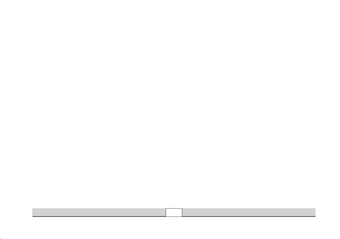
Schaltbare Funktionen
STOP
mobile station
systems
1
5
central
station
60212
f0
f0f8
f8
60652
Spitzensignal
Betriebsgeräusch
Geräusch: Pfeife
TELEX-Kupplung
Geräusch: Druckluft
Geräusch: Hauptschalter
Geräusch: Schaltschütz
Rangiergang (nur ABV)
Geräusch: Bremsenquietschen aus
Betrieb • Operation • Fonctionnement • Exploitatie
6647
Dauernd ein
—
—
—
—
—
—
—
—
6021
function + off
Licht-Taste Taste f0 mit Symbol
f2 Taste 3 mit Symbol Taste f2 mit Symbol
f3 Taste 4 mit Symbol Taste f3 mit Symbol
f4 Taste 6 mit Symbol Taste f4 mit Symbol
— Taste 8 mit Symbol Taste f5 mit Symbol
— Taste 5 mit Symbol Taste f6 mit Symbol
— Taste 1 ohne Symbol Taste f7 mit Symbol
— Taste 2 mit Symbol Taste f8 mit Symbol
— — Taste f9 mit Symbol
7
Page 8

Function
This locomotive has a built-in multi-train electronic circuit
and offers these features:
• Optional operation with DC power (max. ± 18 volts DC),
AC power (with Märklin 32 VA transformer), with Märklin
Delta (only with the 6607 Delta Station), Märklin Digital
(only with the Control Unit), or Märklin Systems (Mobile
Station, Central Station).
• The mode of operation is automatically recognized.
• 80 multi-train addresses can be set. Address that set at
the factory: 14
• Mfx technology for the Mobile Station / Central Station.
Name set at factory:
• Adjustable acceleration (ABV).
• Adjustable Braking delay (ABV)
• Adjustable maximum speed.
• Setting the locomotive parameters electronically with the
Control Unit, Mobile Station or Central Station.
• Built-in sound effects circuit, can only be used in opera
tion with the Control Unit or Märklin Systems. Additional
sound effects that can be controlled.
• The model is designed for operation on Märklin 1 Gauge
track. As the consumer you assume the risk for operating
on other makes of track.
• Minimum radius for operation: 600 mm / 23-2/3“.
• The model has a Telex coupler at both ends that can
be uncoupled with a switching command from Märklin
BR 144
-
1 Gauge models with claw couplers, when you are in
digital/ systems operation. You may have operations pro
-
blems if you use other makes of couplers.
• Except for the headlights, all of the functions are off in the
modes of operation for DC power, AC power, and Märklin
Delta.
Maintenance procedures that become necessary with
normal operation of the locomotive are described below.
Please see your authorized Märklin dealer for repairs or
spare parts.
No warranty or damage claims shall be accepted in those cases where parts
neither manufactured nor approved by Märklin have been installed in Märklin
products or where Märklin products have been converted in such a way that
the non-Märklin parts or the conversion were causal to the defects and / or
damage arising. The burden of presenting evidence and the burden of proof
thereof, that the installation of non-Märklin parts or the conversion in or of
Märklin products was not causal to the defects and / or damage arising, is
borne by the person and / or company responsible for the installation and /
or conversion, or by the customer.
Safety Warnings
• This locomotive is to be used only with an operating
system designed for it (Märklin 6646/6647 AC trans-former, Märklin Delta, Märklin Digital or Märklin Systems).
Under no circumstances should transformers rated for an
input of 220 volts be connected to the American 110 volt
household current system.
• This locomotive must never be supplied with power from
more than one transformer.
•
Pay close attention to the safety warnings in the instructions
for your operating system.
8
Betrieb • Operation • Fonctionnement • Exploitatie
Page 9
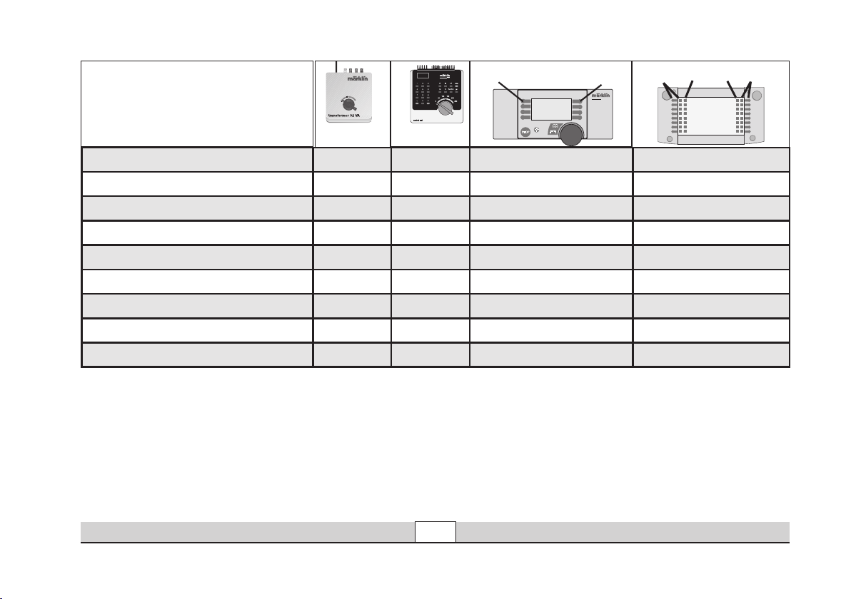
Controllable Functions
STOP
mobile station
systems
1
5
central
station
60212
f0
f0f8
f8
Headlights/marker lights
Locomotive operating sounds
Sound effects: Locomotive whistle
Telex Couplers
Sound effect: Letting off air
Sound Effect: Main relay
Sound effect: Contactor
Switching Range (only ABV)
Sound effect: Squealing brakes off
Betrieb • Operation • Fonctionnement • Exploitatie
6647
Continuously on
—
—
—
—
—
—
—
—
6021
function + off
Headlight button Button f0 with symbol
f2 Button 3 with symbol Button f2 with symbol
f3 Button 4 with symbol Button f3 with symbol
f4 Button 6 with symbol Button f4 with symbol
— Button 8 with symbol Button f5 with symbol
— Button 5 with symbol Button f6 with symbol
— Button 1 without symbol Button f7 with symbol
— Button 2 with symbol Button f8 with symbol
— — Button f9 with symbol
9
Page 10

Fonctionnement
Cette locomotive possède un équipement électronique pour
conduite multitrain:
• Au choix, exploitation conventionnelle avec courant continu
(max ± 18 volts =), courant alternatif (Transformer 32 VA),
exploitation avec Märklin Delta (uniquement Delta Station
6607), Märklin Digital (uniquement Control Unit) ou Märklin
Systems (Mobile Station ou Central Station). Une exploitation
avec d’autres systèmes d’exploitation (courant à largeur
d’impulsion variable, Central Control 1, etc.) n’est pas
possible.
• Le mode d’exploitation est automatiquement détecté.
• Adresses disponibles: 01 – 80.
Adresse encodée en usine:
• Technologie Mfx pour Mobile Station / Central Station.
Nom en codee en usine: BR 144
• Temporisation d’accélération réglable (ABV).
• Temporisation de freinage réglable (ABV).
• Vitesse maximale réglable.
Réglage des paramètres de la loco électroniquement à l’aide de
•
la Control Unit, de la Mobile Station ou de la Central Station.
• Bruiteur électronique intégré, utilisable uniquement lors
d’exploitation avec la Control Unit ou Märklin Systems.
Bruitages complémentaires commutables.
Le modèle réduit est conçu pour rouler sur des voies
•
Märklin 1. Le faire rouler sur des voies d’autres systèmes
comporte des risques.
• Rayon minimal d’inscription en courbe: 600 mm.
14
• Le modèle est équipé d’attelages Telex grâce auxquels il
est possible, en exploitation digital/ systems, de dételer à
distance les modèles Märklin 1 dotés d’attelages à griffe. En
cas d’utilisation d’un système provenant d’un autre fabricant,
des problèmes sont susceptibles de survenir.
• A l’exception des feux de signalisation, les fonctions sont
désactivées en mode d’exploitation courant continu,
courant alternatif et Märklin Delta.
Les travaux d‘entretien occasionnels à effectuer en
exploitation normale sont décrits plus loin. Pour toute
réparation ou remplacement de pièces, adressez-vous à votre
détaillant-spécialiste Märklin.
Tout recours à une garantie commerciale ou contractuelle ou à une demande de dommages-intérêt est exclu si des pièces non autorisées par Märklin sont intégrées dans
les produits Märklin et / ou si les produits Märklin sont transformés et que les pièces
d’autres fabricants montées ou la transformation constituent la cause des défauts
et / ou dommages apparus. C’est à la personne et / ou la société responsable du
montage / de la transformation ou au client qu’incombe la charge de prouver que le
montage des pièces d’autres fabricants sur des produits Märklin ou la transformation
des produits Märklin n’est pas à l’origine des défauts et ou dommages apparus
Remarques importantes sur la sécurité
•
La locomotive ne peut être mise en service qu’avec un
système d’exploitation adéquat (Märklin courant alternatif transformateur 6647, Märklin Delta, Märklin Digital ou Märklin
Systems). N’utilisez en aucun cas de transformateurs pour
une tension à l’entrée de 220 V - 110 V pour les Etats-Unis.
• La locomotive ne peut être alimentée en courant que par
une seule source de courant.
• Veuillez impérativement respecter les remarques sur la
sécurité décrites dans le mode d’emploi en ce qui concerne
le système d’exploitation.
10
Betrieb • Operation • Fonctionnement • Exploitatie
.
Page 11
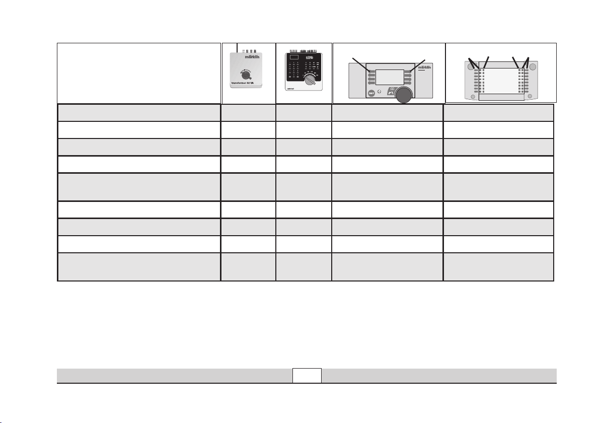
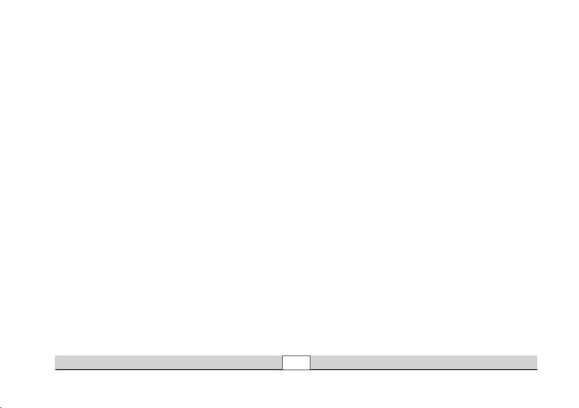
Fonctions commutables
STOP
mobile station
systems
1
5
central
station
60212
f0
f0f8
f8
60652
Eclairage des feux de signalisation
Bruitage locomotive
Bruitage sifflet locomotive
Attelage Telex
Bruitage : Échappement de l‘air
comprimé
Bruitage de disjoncteur principal
Bruitage : Électrovanne
Mode manoeuvre (seulement ABV)
Bruitage : Grincement de freins
désactivé
Betrieb • Operation • Fonctionnement • Exploitatie
6647
Permanence function
—
—
—
—
—
—
—
—
6021
f2 Touche 3 avec symbole Touche f2 avec symbole
f3 Touche 4 avec symbole Touche f3 avec symbole
f4 Touche 6 avec symbole Touche f4 avec symbole
— Touche 8 avec symbole Touche f5 avec symbole
— Touche 5 avec symbole Touche f6 avec symbole
— Touche 1 sans symbole Touche f7 avec symbole
— Touche 2 avec symbole Touche f8 avec symbole
— — Touche f9 avec symbole
11
Touche Lumière Touche f0 avec symbole
Page 12

Werking
Deze loc met ingebouwde digitaalelektronica biedt u:
• Naar keuze conventioneel bedrijf (wisselstroom met de
Transformer 32 VA of gelijkstroom [max +/– 18 Volt=] ),
bedrijf met Märklin Delta (alleen het Delta Station 6607),
Märklin Digital (Control Unit) of het Märklin Systems (Mo
bile Station of Central Station). Het bedrijf met rijregelaars
van andere systemen (bijv. impulsbreedte sturing, gebruik
van de Central-Control 1 (6030) of een dergelijk systeem)
is niet mogelijk.
• Het bedrijfssysteem wordt automatisch herkend.
• Instelbare adressen: 01-80. Vanaf de fabriek:
• Mfx-technologie voor het Mobile Station / Central Station.
Naam af de fabriek: BR 144
•
Instelbare optrekvertraging.
• Instelbare afremvertraging.
• Instelbare maximumsnelheid.
• Elektronische instelling van de locomotiefparameters via
de Control Unit, Mobile Station of Central Station.
• Ingebouwde geluidselektronica, alleen bruikbaar in het
bedrijf met de Control Unit of Märklin Systems. Extra
schakelbare geluiden.
• Het model is ontwikkeld voor het gebruik op het Märklin
Spoor 1 railsysteem. Het gebruik op een ander railsysteem geschied op eigen risico.
• Berijdbare minimumradius: 600 mm.
14.
• Het model beschikt zowel voor als achter over een telexkoppeling. Hiermee kunnen in digitaal/ systems bedrijf
Märklin 1- modellen voorzien van klauwkoppellingen met
een schakelcommando afgekoppeld worden. Bij het ge
bruik van koppelingssystemen van andere fabrikanten zijn
storingen niet uit te sluiten.
-
De in het normale bedrijf voorkomende onderhoudswerkzaamheden zijn verderop beschreven. Voor reparatie of
onderdelen kunt u zich tot uw Märklin winkelier wenden.
Elke aanspraak op garantie en schadevergoeding is uitgesloten, wanneer
in Märklin-producten niet door Märklin vrijgegeven vreemde onderdelen
ingebouwd en / of Märklin-producten omgebouwd worden en de ingebou
wde vreemde onderdelen resp. de ombouw oorzaak van nadien opgetreden
defecten en / of schade was. De aantoonplicht en de bewijslijst daaromtrent,
dat de inbouw van vreemde onderdelen in Märklin-producten of de ombouw
van Märklin-producten niet de oorzaak van opgetreden defecten en / of
schade is geweest, berust bij de voor de inbouw en/of ombouw verantwoordelijke persoon en / of firma danwel bij de klant.
Veiligheidsvoorschriften
• De loc mag alleen met een daarvoor bestemd bedrjfssysteem (Märklin wisselstroom transformator 6647, Mär
klin Delta, Märklin digitaal of Märklin Systems) gebruikt
worden.
• De loc mag niet vanuit meer dan één stroomvoorziening
gelijktijdig gevoed worden.
• Lees ook aandachtig de veiligheidsvoorschriften in de
gebruiksaanwijzing van uw bedrijfssysteem.
-
-
-
-
12
Betrieb • Operation • Fonctionnement • Exploitatie
Page 13
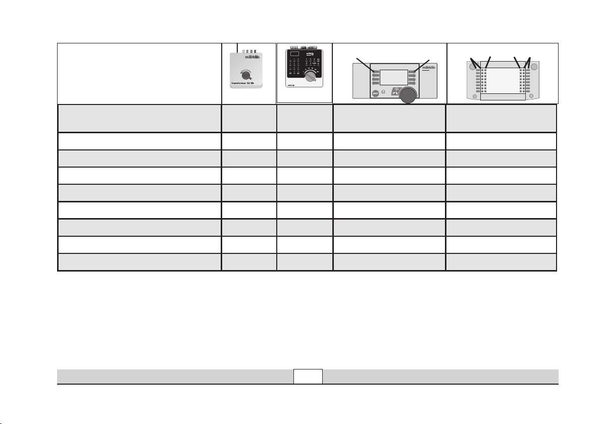
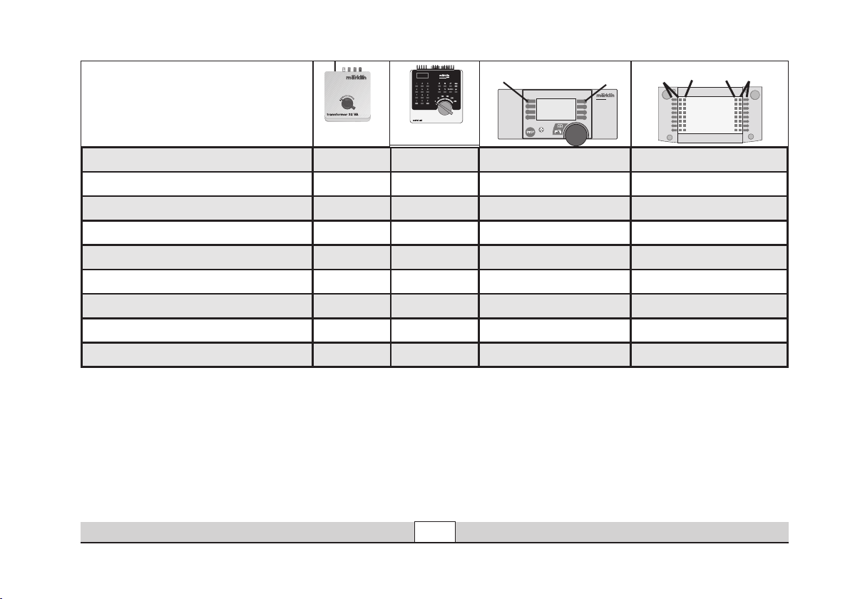
Schakelbare functies
STOP
mobile station
systems
1
5
central
station
60212
f0
f0f8
f8
60652
Frontverlichting rijrichtingafhankelijk continu
Geluid perslucht
Geluid: locfluit
Telexkoppeling
Geluid: perslucht afblazen
Geluid van de hoofdschakelaar
Geluid: schakelwals
Rangeerstand (alleen ABV)
Geluid: piepende remmen uit
Betrieb • Operation • Fonctionnement • Exploitatie
6647
aan
—
—
—
—
—
—
—
—
6021
functie +
Verlichtingstoets Toets f0 met symbool
off
f2 Toets 3 met symbool Toets f2 met symbool
f3 Toets 4 met symbool Toets f3 met symbool
f4 Toets 6 met symbool Toets f4 met symbool
— Toets 8 met symbool Toets f5 met symbool
— Toets 5 met symbool Toets f6 met symbool
— Toets 1 zonder symbool Toets f7 met symbool
— Toets 2 met symbool Toets f8 met symbool
— — Toets f9 met symbool
13
Page 14

Anschluss der Gleisanlage
Um Spannungsverluste auf der Anlage zu vermeiden ist
immer auf gutes Zusammenpassen der Schienenverbindungslaschen zu achten. Alle 2 bis 3 m ist eine neue
Stromeinspeisung über die Anschlussklemmen 5654
empfehlenswert.
Für den konventionellen Betrieb der Lok muss das Anschlussgleis entstört werden. Dazu ist das Entstörset
104770 zu verwenden. Für Digitalbetrieb ist das Entstörset
nicht geeignet.
Befahren von Steigungen
Im Gegensatz zum Vorbild können mit einer Modellbahn
auch größere Steigungen befahren werden. Im Normalfall
sollte eine Steigung bei maximal 3 Prozent liegen. Im Ex
tremfall sind bei entsprechend eingeschränkter Zugleistung
maximal 5 Prozent möglich. Der Anfang und das Ende der
Steigung sind auf jeden Fall auszurunden.
Der Unterschied in der Steigung zwischen zwei mindestens 300 mm langen Gleisstücken darf maximal 1 bis 1,5
Prozent betragen.
-
Connections between the track layout and
the transformer
Rail joiners must fit well on the rails of the track to which
they are joined to avoid voltage drop on the layout. We
recommend that you install feeder wires every 2 to 3 meters
(7 to 10 feet) using the 5654 feeder clips.
The feeder track must be equipped to prevent interference
with radio and television reception, when the powered
rail car is to be run in conventional operation. The 104770
interference suppression set is to be used for this purpose.
The interference suppression set is not suitable for digital
operation.
Operating the locomotive on grades
In contrast to the prototype a locomotive on a model
railroad can operate up steeper grades. As a general rule a
grade should be no steeper than 3%. In extreme situations
a maximum grade of 5% is permissible, keeping in mind
that the locomotive’s tractive effort will be less. The begin
ning and the end of the grade must always work gradually
up to maximum grade for the route. The maximum allowab
le difference in grade between two track sections, each
with a minimum length of 300 mm (11-3/4“) is 1 to 1.5
percent.
-
-
Betrieb auf der Anlage • Operation on a layout • Exploitation sur réseau • Bedrijf op een modelbaan
14
Page 15

Connexion des voies ferrées
Pour éviter des pertes de potentiel sur l’installation, il
faut veiller à ce que les éclisses de liaison des rails soient
toujours parfaitement adaptées. Une nouvelle alimentation
électrique est conseillée tous les 2 à 3 m au moyen des
griffes d’alimentation 5654.
Pour l’exploitation de la rame automotrice en mode conventionnel, la voie de raccordement doit être déparasitée.
A cet effet, utiliser le set de déparasitage réf. 104770. Le
set de déparasitage ne convient pas pour l’exploitation en
mode numérique.
Franchissement des côtes
Contrairement à l’original, la maquette est également en
mesure de franchir des côtes assez importantes. En temps
normal, une côte devrait étre de l’ordre de 3% maximum. A
l’extrême limite, 5% sont envisageables avec une puissance du train réduite en consequence. Le début et la fin
de la côte doivent en tous cas étre arrondis. La différence
de pente entre deux éléments de voie d’au moins 300 mm
de longueur doit étre de 1 à 1,5% maximum.
Aansluiting van de sporen
Om spanningsverlies op de modelbaan te voorkomen
moeten de raillassen altijd goed op elkaar aansluiten. Om
de 2 à 3 meter moet de voeding opnieuw op de rails gezet
worden.Daarbij zijn de aansluitklemmen 5654 aan te raden.
Voor het conventionele bedrijf met de het treinstel dient
de aansluitrail te worden ontstoort. Hiervoor dient men de
ontstoor-set 104770 te gebruiken.Voor het digitale bedrijf is
deze ontstoor-set niet geschikt.
Berijden van hellingen
In tegenstelling tot het grote voorbeeld kunnen met een
modelbaan ook grotere hellingen bereden worden. Normaal
moet een helling maximaal
3 procent zijn. In extreme gevallen is maximaal 5 procent
mogelijk, maar dan moet rekening gehouden worden met
een evenredig verlies aan vermogen. Het begin en het einde
van de helling moeten altijd gerond worden.
Het verschil in de helling tussen twee tenminste 300 mm
lange railstukken mag maximaal 1 à 1,5 procent bedragen.
Betrieb • Operation • Fonctionnement • Exploitatie
15
Page 16

Lokparameter einstellen
mit der Control Unit
1. Voraussetzung: Aufbau wie Grafik S.
17. Nur die zu verändernde Lok ist
auf dem Gleis.
2. „Stop“- und „Go“-Taste gleichzeitig
drücken, bis „99“ in der Anzeige
aufblinkt.
3. „Stop“-Taste drücken.
4. Lokadresse „80“ eingeben.
5. Umschaltbefehl am Fahrregler
halten. Während des Haltens die
„Go“-Taste drücken.
6. Licht der Lok blinkt langsam. Wenn
nicht, ab Schritt 2 wiederholen.
7. Registernummer für den zu ändern
den Parameter eingeben (=> Liste
auf Seite 19).
8. Fahrtrichtungswechsel betätigen.
9. Licht blinkt schnell
10.Neuen Wert eingeben (=> Liste auf
Seite 19).
11.Fahrtrichtungswechsel betätgen.
12.Licht blinkt langsam (Ausnahme
Werkreset)
13.Nächste Parametereinstellung ab 6.
oder beenden mit 14.
14.Vorgang beenden mit Drücken der
„Stop“-Taste. Anschließend Drücken
der „Go“-Taste.
Setting Locomotive Parameters with the Control
Unit
1. Requirement: Setup as in diagram
on page 17. Only the locomotive to
be changed can be on the track.
2. Press the “Stop” and “Go” at the
same time until “99” blinks in the
display.
3. Press the “Stop” button.
4. Enter the locomotive address „80“.
5. Hold the control knob in the reverse
direction area. While holding the
control knob here, press the „Go“
button.
6. The headlights on the locomotive
will blink slowly. If they don‘t, repeat
Step 2.
7. Enter the register number for the
parameter to be changed (=> List
on page 19).
8. Active the change of direction.
9. The headlights will blink rapidly.
10.Enter the new value (=>List on
page 19).
11.Active the change of direction.
12.The headlights will blink slowly
(exception: factory reset)
13.Enter the next parameter setting
from 6 or end with 14.
14.End the process by pressing the
„Stop“ button. Then press the „Go“
button.
Réglage des paramètres de
la loco avec la Control Unit
1.
Condition: Montage comme sur illustration en page 17 Seule la loco à modifier
peut se trouver sur la voie.
2.
Pressez simultanément les touches
„Stop“ et „Go“ jusqu’à ce que le
nombre „99“ clignote sur l’écran
3. Pressez la touche „Stop“.
4. Introduisez l’adresse de loco „80“.
5.
Maintenir l’ordre de commutation sur
le régulateur de marche. Durant le
maintien, appuyer sur la touche „Go“.
6. Les feux de la locomotive clignotent
lentement. Dans le cas contraire,
renouveler l’opération à partir de
l’étape 2.
7. Indiquer le numéro ’enregistrement
pour le paramètre à modifier (=>
liste page 19).
8.
Activer l’inversion du sens de marche.
9. Les feux clignotent rapidement.
10. Entrer la nouvelle valeur (=> liste
page 19).
11.
Activer l’inversion du sens de marche.
12. Les feux clignotent lentement (exception : réinitialisation aux valeurs
d’usine)
13. Définition de paramètres suivante
à partir du point 6 ou terminer par
le point 14.
14. Terminez le processus en pressant
la touche „Stop“. Ensuite, pressez la
touche „Go“.
.
Locparameters instellen
met de Control Unit
1.
Voorwaarde: opbouw zoals tekening
op pagina 17. Alleen de loc die gewij
zigd moet worden op de rails.
2. ”Stop”- en ”Go”-toets gelijktijdig
indrukken tot ”99” in het display
oplicht.
3. ”Stop”-toets indrukken.
4. Het adres „80“ invoeren.
5. Omschakelcommando met de rijre
gelaar vasthouden. Tijdens het vasthouden de toets “Go” indrukken.
6. De verlichting van de loc knippert
langzaam. Indien dit niet het geval
is, vanaf stap 2 opnieuw beginnen.
7. Het registernummer van de te
wijzigen parameter invoeren (=> lijst
op pagina 19).
8. Omschakelcommando geven.
9. Verlichting gaat snel knipperen.
10. Nieuwe waarde invoeren (=> lijst
op pagina 19).
11. Omschakelcommando geven.
12. Verlichting knippert langzaam
(uitgezonderd bij decoder reset)
13. Volgende parameterinstelling of
beëindigen met 14
14. Sessie beëindigen door het indrukken van de toets “Stop”. Aansluitend de toets “Go” indrukken.
-
-
16
Betrieb • Operation • Fonctionnement • Exploitatie
Page 17
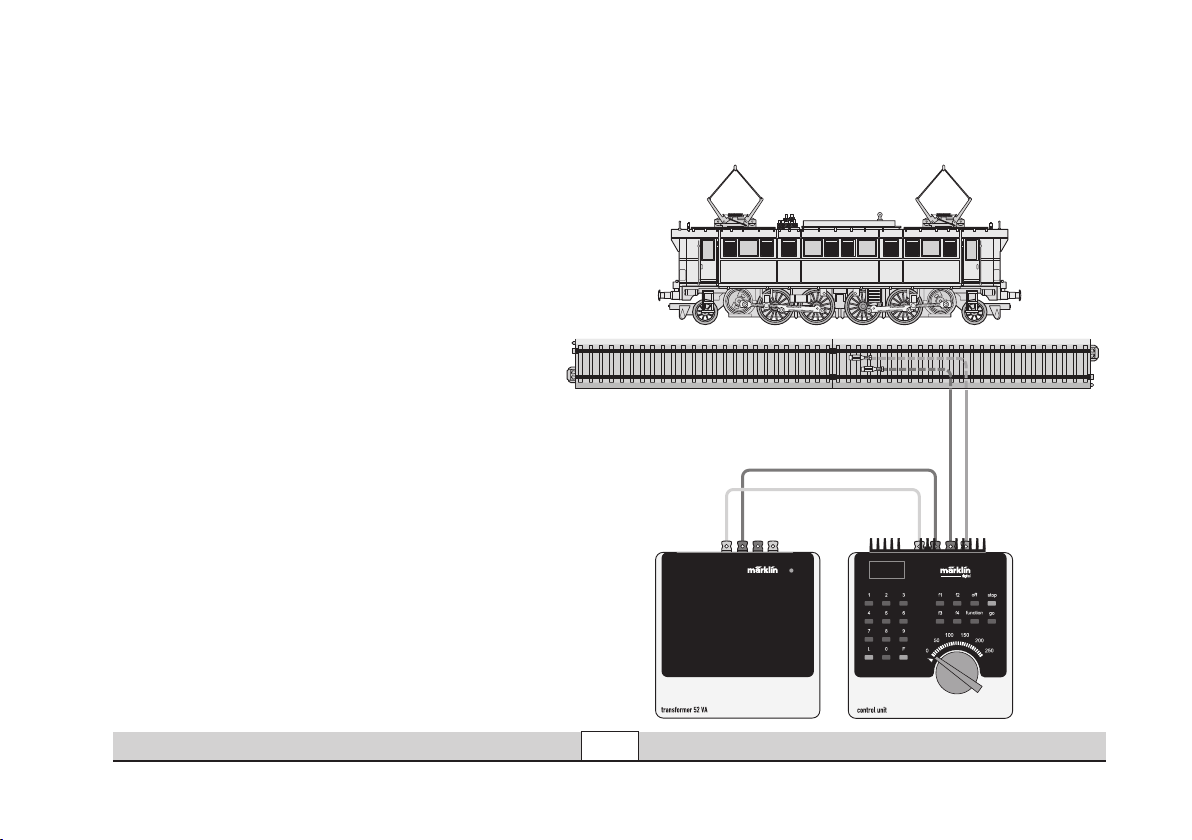
Lokparameter mit Control Unit ändern.
Changing Locomotive Parameters with the Control Unit.
Modification des paramètres avec la Control Unit.
Locparameter met de Control Unit.
Betrieb • Operation • Fonctionnement • Exploitatie
17
Page 18
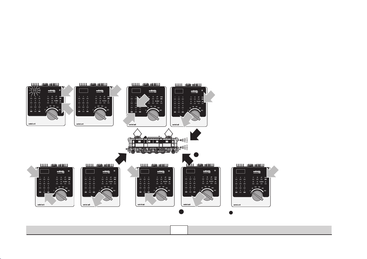
1
80
1
Lokparameter verändern mit der Control Unit 6021.
1
1
99
1
2
80
2
1
01
01
1
1
2
10
10
1
11
14
12
Changing Locomotive Parameters with the 6021 Control Unit.
Modification des paramètres de la locomotive avec la Control Unit 6021.
Locparameter wijzigen met de Control Unit.
18
Betrieb • Operation • Fonctionnement • Exploitatie
Page 19
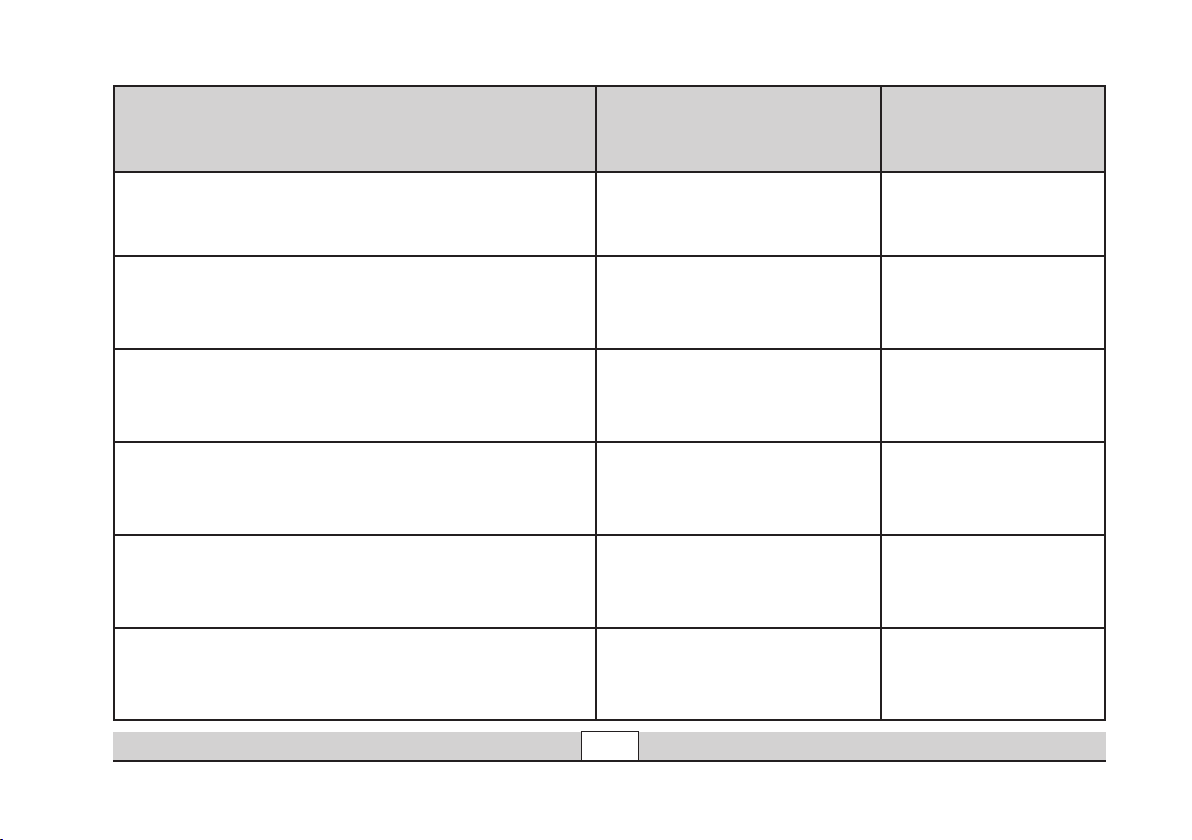
Parameter • Parameter • Paramètre • Parameter •
Parámetro • Parametro • Parameter • Parameter
Adresse • Address • Adresse • Adres
Anfahrverzögerung • Acceleration delay • Temoprisation accélération • Optrekvertraging
Bremsverzögerung • Braking delay • Temporisation de freinage •
Afremvertraging
Höchstgeschwindigkeit • Maximum speed •
Vitesse maximale • Maximumsneilheid
Rückstellen auf Serienwerte • Reset to series value • Remettre
aux valeurs de série • Terugzetten naar serie-instellingen •
Lautstärke • Volume • Volume haut-parleur • Volume
Register • Register •
Registre • Register •
Registro • Registro •
Register • Register
01 01 - 80
03 01 - 63
04 01 - 63
05 01 - 63
08 08
63 01 - 63
Wert • Value • Valeur •
Waarde • Valor • Valore •
Värde • Værdi
Betrieb • Operation • Fonctionnement • Exploitatie
19
Page 20

Betrieb mit Mobile Station / Central Station
• Lok aufgleisen. Die Lok meldet sich selbsttätig in der
Lokliste an.
• Keine Rückmeldung der Lok, wenn:
bei Mobile Station der Geschwindigkeitsbalken blinkt
bei Central Station das mfx-Symbol unterstrichen ist
• Lok abmelden:
1. Lok vom Gleis entfernen.
2. Lokeintrag löschen.
Eine Adressänderung ist nicht notwendig.
Lokparameter mit der Mobile Station / Central Station
verändern
1. Lok aus der Lokliste auswählen.
2. Zum Untermenü „LOKÄNDERN“ wechseln.
3. Zum Untermenü „VMAX“ (Höchstgeschwindigkeit),
„ACC“ (Beschleunigung), „DEC“ (Bremsen),
„VOL“ (Lautstärke, max. 72%) oder
„RESET“ (Decoder auf Werkeinstellung zurück) wechseln.
4. Neuen Wert eingeben und übernehmen.
Beachten Sie die Hinweise in der Anleitung zur
Mobile Station / Central Station.
Zugunsten der guten Fahreigenschaften ist an dem Modell
die VMAX auf 54% (Mobile Station) bzw.
138 (Central Station) voreingestellt. Ein weiteres Anheben
dieses Wertes hat keine Geschwindigkeitserhöhung zur Fol
ge sondern beeinflusst nur die Fahreigenschaften negativ.
Operation with the Mobile Station / Central Station
• Set the locomotive on the track. The locomotive automatically registers itself in the locomotive list.
• The locomotive will not communicate back to the control
ler when:
the speed bar on the Mobile Station blinks.
the mfx symbol has a line beneath it on the Central Station.
• Taking the locomotive out of the locomotive list:
1. Remove the locomotive from the track.
2. Delete the locomotive entry.
It is not necessary to change the address.
Changing Locomotive Parameters with the
Mobile Station / Central Station
1. Select the locomotive from the locomotive list.
2. Change to the submenu “EDIT LOC”.
3. Go to the submenu „VMAX“ (maximum speed),
„ACC“ (acceleration), „DEC“ (brakes),
„VOL“ (volume max. 72%) or
„RESET“ (resetting the decoder to factory default settings)
4. Enter the new value and accept it into the system.
Please note the information in the instructions for the Mobile Station / Central Station.
The VMAX has been preset at 54% (Mobile Station) and
at 138 (Central Station) on the model in order to give good
-
running characteristics. Raising this value further will not
increase the speed; it will only have a negative effect on the
running characteristics.
20
Betrieb • Operation • Fonctionnement • Exploitatie
-
.
Page 21

Exploitation avec Mobile Station / Central Station
• Enrailler la locomotive. La locomotive signale automatiquement sa présence dans la liste des locos.
• Pas de rétrosignalisation de la locomotive lorsque :
- la barre de vitesse clignote pour Mobile Station
- le symbole mfx est souligné pour Central Station
• Appeler loco:
1. Enlever loco de la voie.
2. Effacer entrée loco.
Une modification de l’adresse n’est pas nécessaire.
Bedrijf met Mobile Station / Central Station
• Loc op de rails plaatsen. De loc meldt zichzelf aan in de
loclijst.
• Geen terugmelding van de loc als:
bij het Mobile Station de snelheidsbalk knippert
bij het Central Station het mfx-symbool onderstreept is
• Loc afmelden:
1. loc van de rails nemen
2. loc invoer wissen.
Het wijzigen van het adres is niet nodig.
Modification des paramètres de la loco avec la
Mobile Station/Central Station
1. Sélectionnez la loco dans la liste.
2. Allez au sous-menu „MODIF LOC“.
3. Ouvrir le sous-menu « VMAX » (vitesse maximale),
« ACC » (accélération), « DEC » (freinage),
« VOL » (volume max. 72%) ou
« RESET » (réinitialisation du décodeur aux valeurs d’usine).
4. Entrez la nouvelle valeur et acceptez.
Respectez les remarques mentionnées dans l’instruction
accompagnant la Mobile Station / Central Station.
En faveur de l’une des bonnes caractéristiques de roulement,
la VMAX du modèle est préréglée sur
54% (Mobile Station) ou 138 (Central Station).
L’augmentation de cette valeur n’augmentera pas la vitesse,
mais risque uniquement d’altérer les caractéristiques de
roulement.
Betrieb • Operation • Fonctionnement • Exploitatie
Locparameter wijzigen met het Mobile Station/
Central Station
1. Loc uit de loclijst kiezen.
2. Ga naar het nevenmenu ”WIJZIG LOC”.
3. Naar het nevenmenu “VMAX” (maximumsnelheid)
“ACC” (optrekken), “DEC” (afremmen), “VOL” (volume
max. 72%) of “RESET” (decoder terugzetten naar fabrieksinstelling) omschakelen.
4. Nieuwe waarde invoeren en overnemen.
Lees ook de opmerkingen in de gebruiksaanwijzing van het
Mobile Station / Central Station.
Voor het verbeteren van de rijeigenschappen is bij het mo
del de maximumsnelheid op 54% (Mobile Station) dan wel
138 (Central Station) ingesteld. Het verhogen van deze vooringestelde waarde heeft geen invloed op de maximumsnel
heid, maar beïnvloed alleen de rijeigenschappen negatief.
21
-
-
Page 22
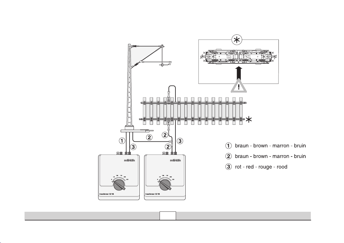
Bei Oberleitungsbetrieb:
Rückleitermarkierung
(Stern) an der Lokunterseite
beachten!
With catenary operation:
Pay attention to the ground
return marking (star) on the
underside of the locomotive!
En cas d’alimentation par
caténaire:
Tenir compte du marquage
relatif au retour de courant
(étoile), situé sous la locomotive!
Bij bovenleidingsbedrijf:
Let op de retourleidingmarkering (sterretje) aan de
onderkant van de loc.
Betrieb auf der Anlage • Operation on a layout • Exploitation sur réseau • Bedrijf op een modelbaan
22
Page 23
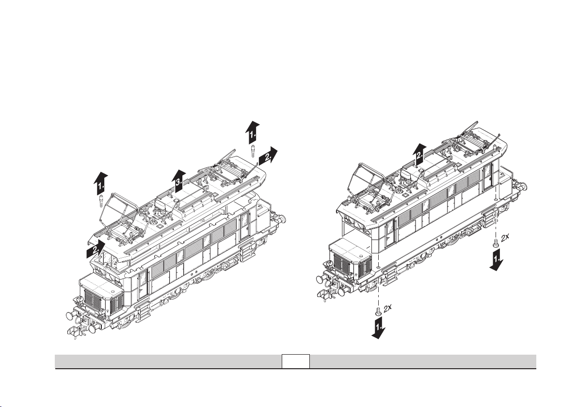
Dach abnehmen / Gehäuse entfernen
Removing the roof / Removing the body
Enlever toiture / enlever caisse
Dak er afnemen / kap verwijderen
23
Wartung • Maintenance • Entretien • Onderhoud
Page 24
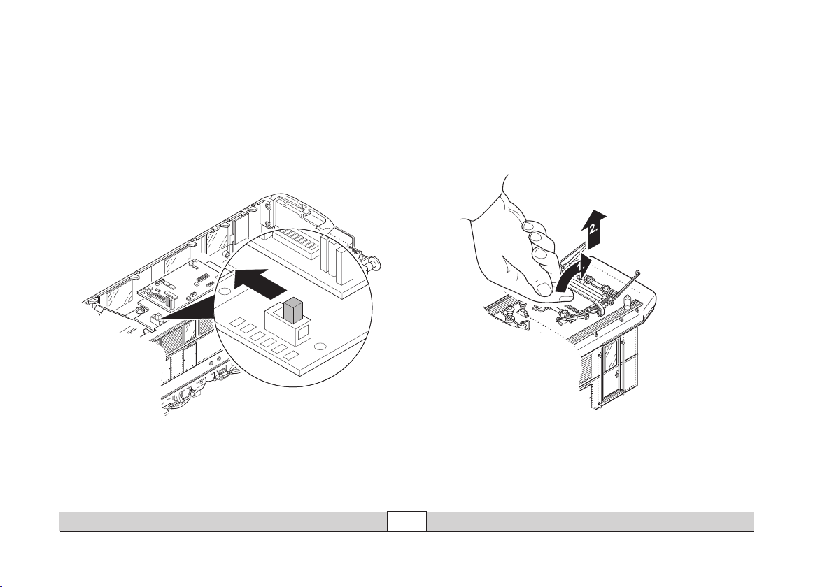
Umschalten auf Oberleitungsbetrieb
Switching to catenary operation
Passage sur exploitation par caténaire
Omschakelen naar bovenleidingsbedrijf
Pantograph lösen
Releasing the pantograph
Détacher le pantographe
Pantograaf los maken
24
Wartung • Maintenance • Entretien • Onderhoud
Page 25
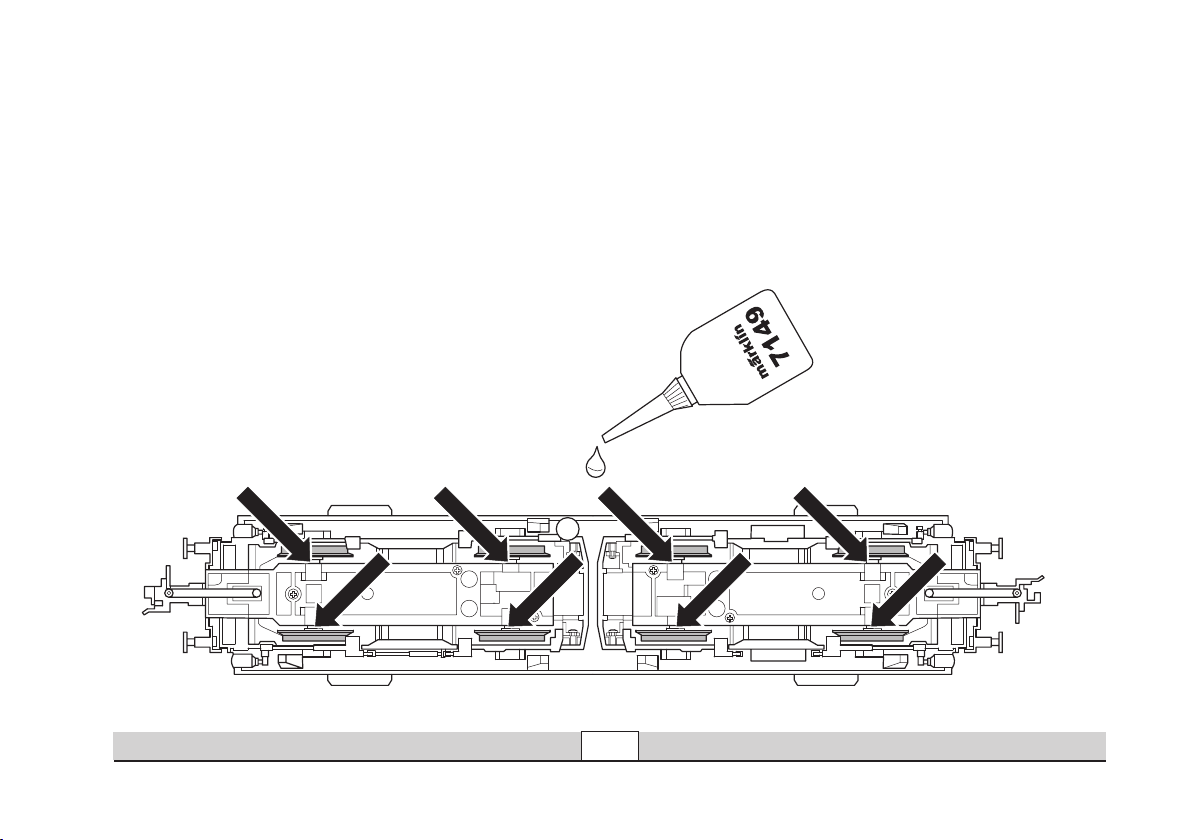
Fahrgestell ölen
Oiling the trucks
Graisser le mécanisme de roulement
Aandrijving oliën
25
Wartung • Maintenance • Entretien • Onderhoud
Page 26
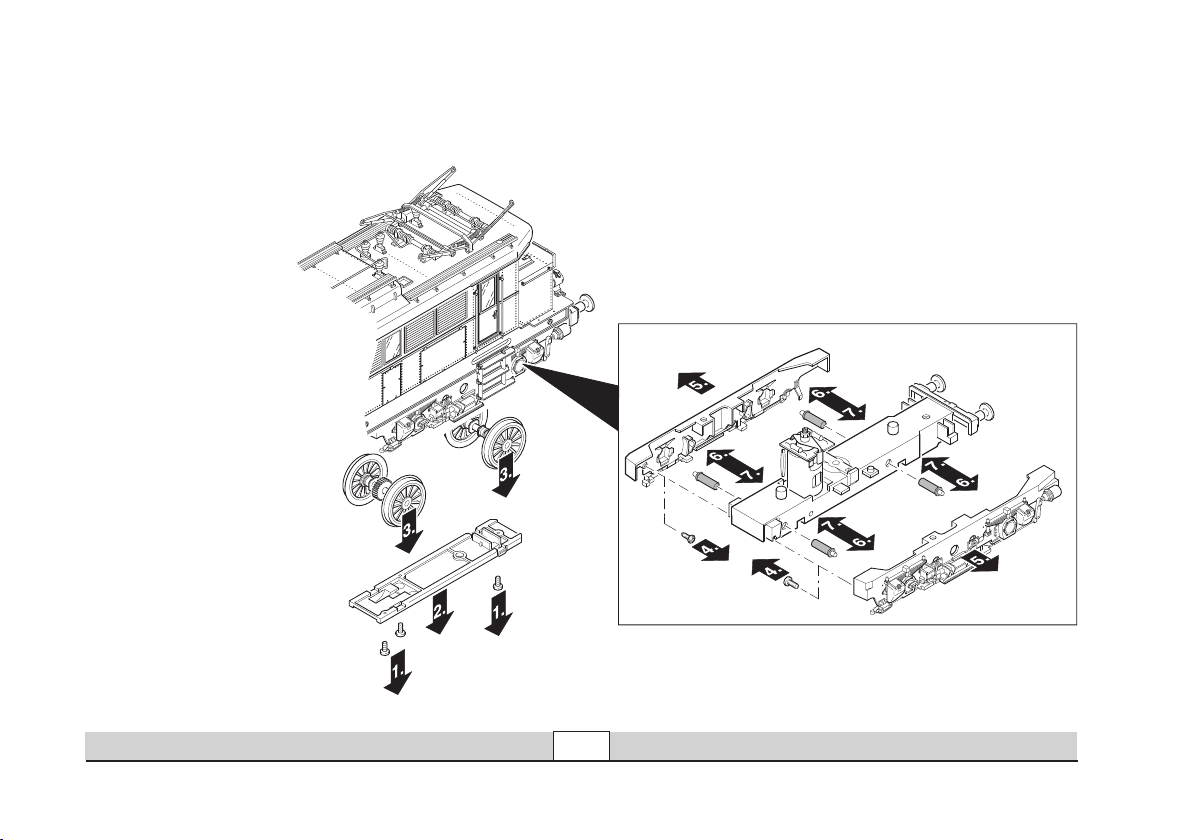
Rad-Schleifer wechseln
Changing the wheel pickups
Remplacer frotteur de roues
Wielas-sleper vervangen
408 841 rot – red – rouge – rood
408 842 braun – brown – marron – bruin
26
Wartung • Maintenance • Entretien • Onderhoud
Page 27
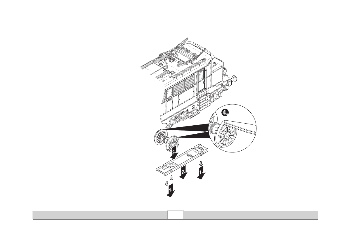
Haftreifen wechseln
Changing traction tires
Remplacer bandages
Antislipband vervangen
27
Wartung • Maintenance • Entretien • Onderhoud
Page 28

Dach aufsetzen
Reinstalling the roof
Reposer toiture
Dak plaatsen
28
Wartung • Maintenance • Entretien • Onderhoud
Page 29

Pflegehinweis
Diese Lok kann auch im
Außenbereich eingesetzt
werden. Ein Betrieb bei
schlechten Witterungsbedingungen (Schnee oder
Regen) wird nicht empfoh
len.
Antrieb und Elektronik sind
gegen Spritzwasser geschützt. Wasserdurchfahr
ten sind nicht möglich.
Es wird empfohlen, das
Modell nach dem Betrieb
im Außenbereich auf Ver
schmutzung zu prüfen und
gegebenenfalls trocken mit
Staubtuch oder Pinsel zu
reinigen. Nie die Lok unter
fließendem Wasser reinigen.
Hinweis: Reinigungsmittel
können die Farbgebung
oder die Beschriftung der
Lok angreifen und beschä
digen.
-
-
-
-
Tips For The Care Of
Your Locomotive
This locomotive can also
be used outdoors. We do
not recommend running the
locomotive in bad weather
(snow or rain).
The mechanism and the
electronic circuit are protec
ted against spraying water.
The locomotive cannot be
run through water.
We recommend that you
check the locomotive over
after running in outdoors
and that you dry it with
a cloth or clean in with a
brush if necessary. Never
clean the locomotive with
running water.
Important: Cleaning fluids
can attack the finish and
lettering for the locomotive
and damage them.
Remarque sur
l’entretien
Cette locomotive peut également être mise en service
à l’air libre. Une utilisation
par mauvais temps (neige
ou pluie) n’est pas recom
mandée.
Le moteur et l’électro-ni-
que sont protégés contre
les projections d’eau. Des
trajets dans l’eau ne sont
pas possibles.
Il est recommandé de
vérifier l’encrassement du
modèle après une utilisation à l’extérieur et, le cas
échéant, de nettoyer le
modèle à l’aide d’un chiffon
doux ou un pinceau. Ne
jamais nettoyer le modèle
au jet d’eau.
Attention: Certains solvants
et produits d’entretien peu
vent altérer le marquage et
la peinture du modèle.
Opmerkingen voor het
onderhoud
Deze loc kan ook buiten gebruikt worden. Het gebruik
bij slecht weer (sneeuw of
regen) is niet aan te raden.
-
Aandrijving en elektronica
zijn weliswaar afgeschermd
tegen spatwater maar
rijden door het water is niet
mogelijk.
Het is aan te bevelen het
model na het gebruik buiten
te controleren op vuil en dit
eventueel droog te verwij
deren met een stofdoek of
een zachte kwast. Nooit de
loc onder stromend water
reinigen.
Opmerking: reinigings
middelen kunnen de lak en
de opschriften op de loc
aantasten en beschadigen.
-
-
-
29
Wartung • Maintenance • Entretien • Onderhoud
Page 30
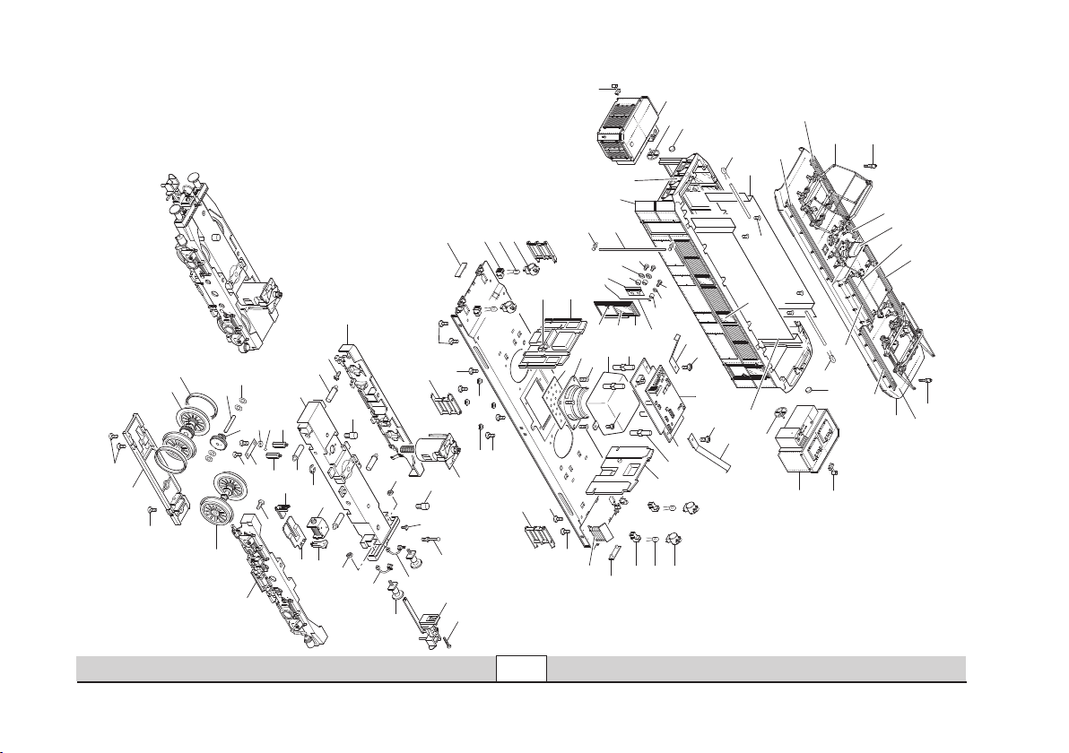
67
7
5
5
5
3
6
7
7
7
7
4
3
8
9
25
29
1
21
22
32
29
8
23
26
10
2
34
10
30
26
24
35
32
16
15
14
13
11
10
12
20
18
17
19
35
9
25
33
36
28
36
39
38
37
28
26
45
8
46
47
42
27
27
44
41
40
45
8
46
47
31
27
27
43
64
52
31
76
75
73
60
58
53
66
65
57
71
72
70
73
69
68
63
59
74
74
27
31
48
50
49
54
56
55
51
31
53
53
62
61
73
77
73
73
Details der Darstellung
können von dem Modell
abweichen
30
Wartung • Maintenance • Entretien • Onderhoud
Page 31
Lfd. Nr. Benennung
Bestell-Nr.
1 Dach 410 819
2 Gehäuse 107 281
3 Pfeife 409 289
4 Dach komplett 107 279
mit
5 Dachleitungen u. Isolatoren 116 407
6 Dachstromabnehmer 451 966
und
7 Laufstege 116 408
8 LED, gelb 503 004
9 Lampenglas 451 877
10 Fenstersortiment 116 414
11 Türe, rechts 451 989
Türe, links 451 984
12 Türklinke, rechts 451 991
Türklinke, links 451 987
13 Türfeder, rechts 451 994
Türfeder, links 451 993
14 Distanzrohr 451 951
15 Unterlegscheibe 722 250
16 Zylinderschraube 404 528
17 Türhalter 451 992
18 Distanzrohr 451 955
19 Unterlegscheibe 721 180
20 Linsenschraube 785 170
21 Griffstange 452 001
22 Stangenhalter 408 848
23 Vorbau, vorn 452 011
oder
24 Vorbau, hinten 452 003
mit
25 Handrad 452 009
26 Schildhalter 408 848
27 Linsenschraube 587 100
Lfd. Nr. Benennung
Bestell-Nr.
Lok-Unterteil
28 Querwand 452 026
29 Längswand 452 117
30 Schraube 650 334
31 Mutter 492 880
32 Zuleitung 452 029
33 Decoder 112 395
34 Leiterplatte Telex 104 729
Grundleiterplatte 452 028
Leiterplatte Schnittstelle 651 767
35 Schraube 593 040
36 Abstandshülse 219 131
37 Lautsprecher 411 378
38 Schraube 650 016
39 Gehäuse 204 285
40 Schraube 593 040
41 Rahmeneinlage 452 032
42 Kühlschlange 107 314
43 Treppe, links 452 023
44 Treppe, rechts 452 024
45 Laterne 213 237
46 Lampenhalter 541 250
47 Nummernschild 107 313
48 Haltestange 452 078
49 Kupplung 540 061
50 Linsenschraube 547 710
51 Hubmagnet mit Kern 544 960
52 Linsenschraube 785 170
53 Kupplungsmechanik 227 057
54 Bremsschlauch, links 330 950
55 Bremsschlauch, rechts 330 960
56 Puffer 493 520
57 Drehgestellrahmen 452 036
58 Sicherungsscheibe 608 130
59 Drehgestellblende, hinten links 452 044
Drehgestellblende, vorne links 452 081
31
Lfd. Nr. Benennung
Bestell-Nr.
60 Drehgestellblende, hinten rechts 452 041
Drehgestellblende, vorne rechts 452 082
61 Treibradsatz 107 321
62 Haftreifen 591 500
63 Radsatz 107 319
64 Motor 452 073
65 Lagerhalter, lang 452 074
66 Lagerhalter, kurz 452 075
67 Ritzel 452 068
68 Passkerbstift 478 550
69 Unterlegscheibe 722 080
70 Schneckenlager, unten 451 002
71 Kugel 462 180
72 Unterlage 650 628
73 Linsenschraube 588 230
74 Anschlagstift 452 076
75 Radschleifer, rot 408 841
76 Radschleifer, braun 408 842
77 Abdeckung 452 039
Lokführer 602 430
Wartung • Maintenance • Entretien • Onderhoud
Page 32
This device complies with Part 15 of the FCC Rules.
Operation is subject to the following two conditions:
(1) This device may not cause harmful interference, and
(2) this device must accept any interference received, including
interference that may cause undesired operation.
Gebr. Märklin & Cie. GmbH
Postfach 8 60
D-73008 Göppingen
www.maerklin.com
107285 03 07 Ni Ef
Änderungen vorbehalten
© by Gebr. Märklin & Cie GmbH
 Loading...