

Page 1
Model of the class 4000 „Big Boy”
Page 2

Information about the Prototype
The steep ascents with inclines of up to 17.7 ‰ on
the route between Ogden / Utah and Cheyenne /
Wyoming put the Union Pacific to considerable operating expense at the end of the 1930s. Up to 4 steam
locomotives had to be coupled in line together in order
to pull the heavy goods trains along this mountainous
section of track.
The American Locomotive Corporation was therefore
charged with building a steam locomotive that could
convey these 3600-tonne trains along this route on
its own. The result was the Class 4000, taken into
service in 1941 and soon known across the world
under its nickname of “Big Boy”. With its performance
details and dimensions, this 4-8-8-4 axle locomotive
put everything before it in the shade and is still today
the largest steam engine in the world.
Specifications:
Total length of locomotive: 40.51 m
Total weight: 540 t
Output: 5884 kW (7000 PS)
Travelling speed: 64 km/h
Informationen zum Vorbild
Die steilen Rampen mit bis zu 17,7 ‰ Steigung auf
der Strecke zwischen Ogden / Utah und Cheyenne /
Wyoming stellte die Union Pacific Ende der 30er Jahre
vor einen besonders hohen Betriebsaufwand. Bis zu
4 Dampflokomotiven mussten hintereinander gekuppelt werden, um die schweren Güterzüge über diese
Gebirgsstrecke zu ziehen.
Daher wurde die American Locomotive Corporation
mit dem Bau einer Dampflokomotive beauftragt,
die diese 3600 t schweren Züge alleine über diese
Strecke befördern konnte. Das Ergebnis war die
1941 in Dienst gestellte Class 4000, die unter ihrem
Spitznamen „Big Boy“ weltweit bekannt wurde.
Mit ihren Leistungsdaten und ihren Abmessungen
stellte diese Lok mit der Achsfolge 4-8-8-4 alles
bisher dagewesene in den Schatten und blieb bis
heute die größte Dampflokomotive der Welt.
Technische Daten:
Gesamtlänge der Lok: 40,51 m
Gesamtgewicht: 540 t
Leistung: 5884 kW (7000 PS)
Reisegeschwindigkeit: 64 km/h
2
Page 3

Informations concernant la
locomotive réele
Les pentes raides du tronçon séparant Ogden / Utah
de Cheyenne / Wyoming, avec une grimpée allant
jusqu’à 17,7 ‰, mirent l’Union Pacific à rude épreuve
à la fin des années 30. Il fallut accoupler jusqu’à
4 locomotives à vapeur l’une derrière l’autre pour
arriver à tirer les lourds wagons de marchandises
sur ce trajet montagneux.
C’est la raison pour laquelle l’American Locomotive
Corporation reçut l’ordre de concevoir une locomotive
à vapeur capable de tirer toute seule les trains lourds
de 3600 tonnes sur ce parcours. C’est ainsi que
naquit la «Classe 4000», mise en service en 1941,
qui se fit une réputation dans le monde entier sous
son surnom de «Big Boy». Avec ses performances
et ses dimensions, cette locomotive avec disposition
d’essieux 4-8-8-4 éclipsa tout ce que l’on n’avait
jamais vu jusqu’à présent et resta jusqu’à aujourd’hui
la locomotive à vapeur la plus grosse du monde.
Caractéristiques techniques:
Longueur totale de la locomotive: 40,51 m
Poids total: 540 t
Puissance: 5884 kW (7000 PS)
Vitesse de croisière: 64 km/h
Informatie van het voorbeeld
De steile berghellingen met tot wel 17,7 ‰ steiging
op het traject tussen Ogden / Utah en Cheyenne /
Wyoming noopten de spoormaatschappij Union
Pacific eind jaren dertig tot een bijzonder hoge inzet
van mensen en materieel. Zo’n vier stoomlocomotieven moesten achter elkaar gekoppeld worden, om
de zware goederentreinen op dit traject te kunnen
trekken.
Om die reden werd de American Locomotive Corporation met de bouw van een stoomlocomotief belast,
die deze 3600 t zware treinen op het traject in zijn
eentje aan moest kunnen. Het resultaat was de in
1941 in dienst gestelde Class 4000, die onder zijn
bijnaam „Big Boy” wereldwijd bekend werd.
Met haar prestaties en afmetingen stelde deze loc
met de asindeling 4-8-8-4 alles wat er tot dan toe
gebouwd was in de schaduw en bleef tot op heden
de grootste stoomlocomotief ter wereld.
Technische gegevens:
Totale lengte van de loc: 40,51 m
Totaal gewicht: 540 t
Vermogen: 5884 kW (7000 PK)
Reissnelheid: 64 km/u
3
Page 4

Function
● Possible operating systems:
6646/6647 Märklin Transformer, Märklin Delta,
Märklin Digital, Märklin Systems.
● Recognition of the mode of operation: automatic.
● Addresses that can be set (Control Unit): 01+ 02
to 79+ 80 (Double addresses must always be set
for this locomotive).
Address set at the factory: 40+ 41.
● Mfx technology for the Mobile Station /
Central Station.
● Adjustable acceleration.
● Adjustable Braking delay.
● Adjustable maximum speed.
● Setting the locomotive parameters electronically with
the Control Unit, Mobile Station or Central Station.
● Built-in sound effects circuit, can only be used in
operation with the Control Unit or Märklin Systems.
Additional sound effects that can be controlled.
● Up to 2 smoke generators can be retrofitted into
this locomotive. The smoke generators that have
been installed are always on, when the locomotive
is on a digital layout. Remove the smoke generators before attempting to change locomotive
parameters!
No warranty or damage claims shall be accepted in those cases
where parts neither manufactured nor approved by Märklin have been
installed in Märklin products or where Märklin products have been
converted in such a way that the non-Märklin parts or the conversion
were causal to the defects and / or damage arising. The burden of
presenting evidence and the burden of proof thereof, that the installation of non-Märklin parts or the conversion in or of Märklin products
was not causal to the defects and / or damage arising, is borne by
the person and / or company responsible for the installation and / or
conversion, or by the customer.
Safety Warnings
● This locomotive is to be used only with an operating
system designed for it (Märklin 6646/6647
AC transformer, Märklin Delta, Märklin Digital
or Märklin Systems).
● This locomotive must never be supplied with
power from more than one transformer.
● Pay close attention to the safety warnings in the
instructions for your operating system.
4
Page 5

5
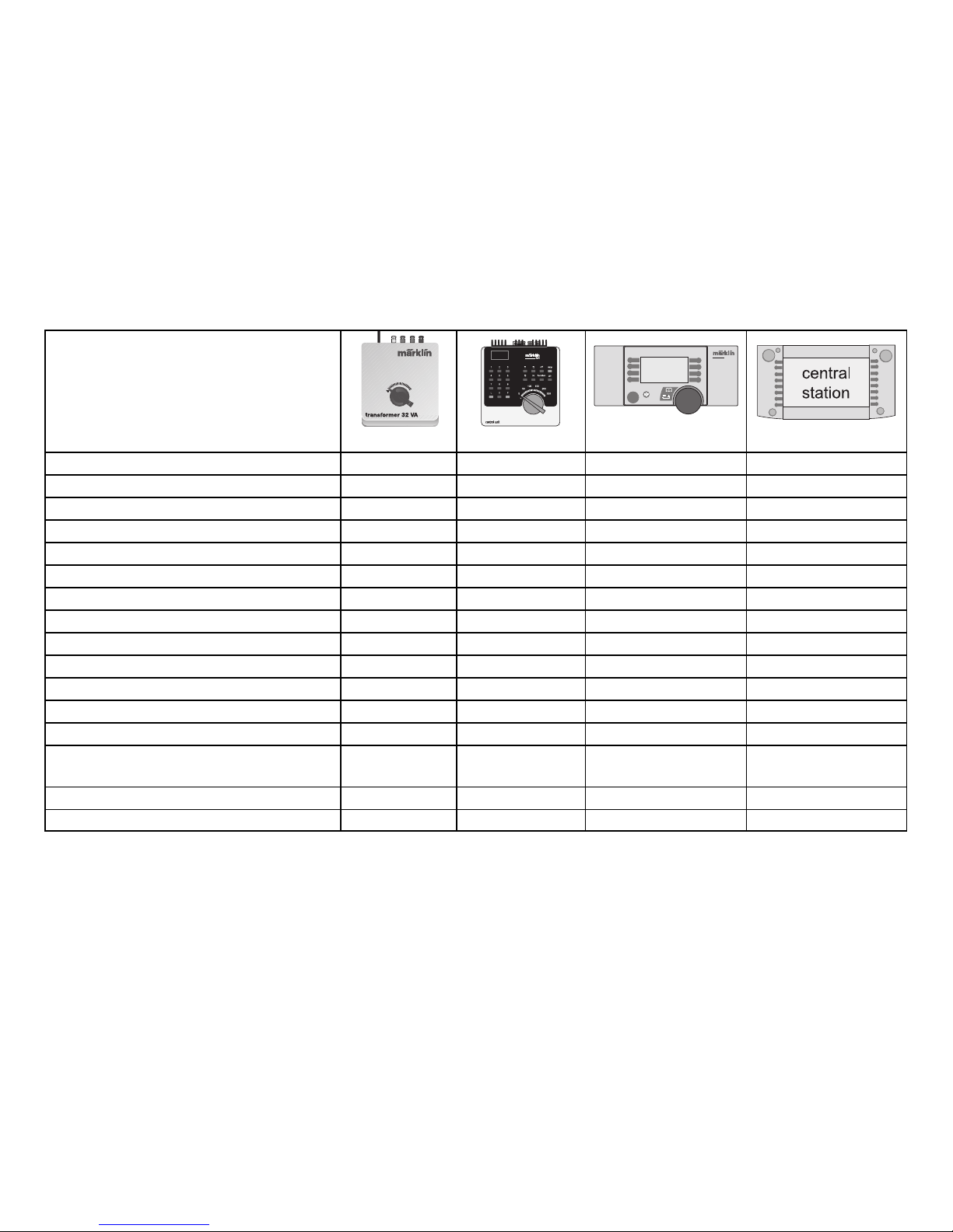
Controllable Functions
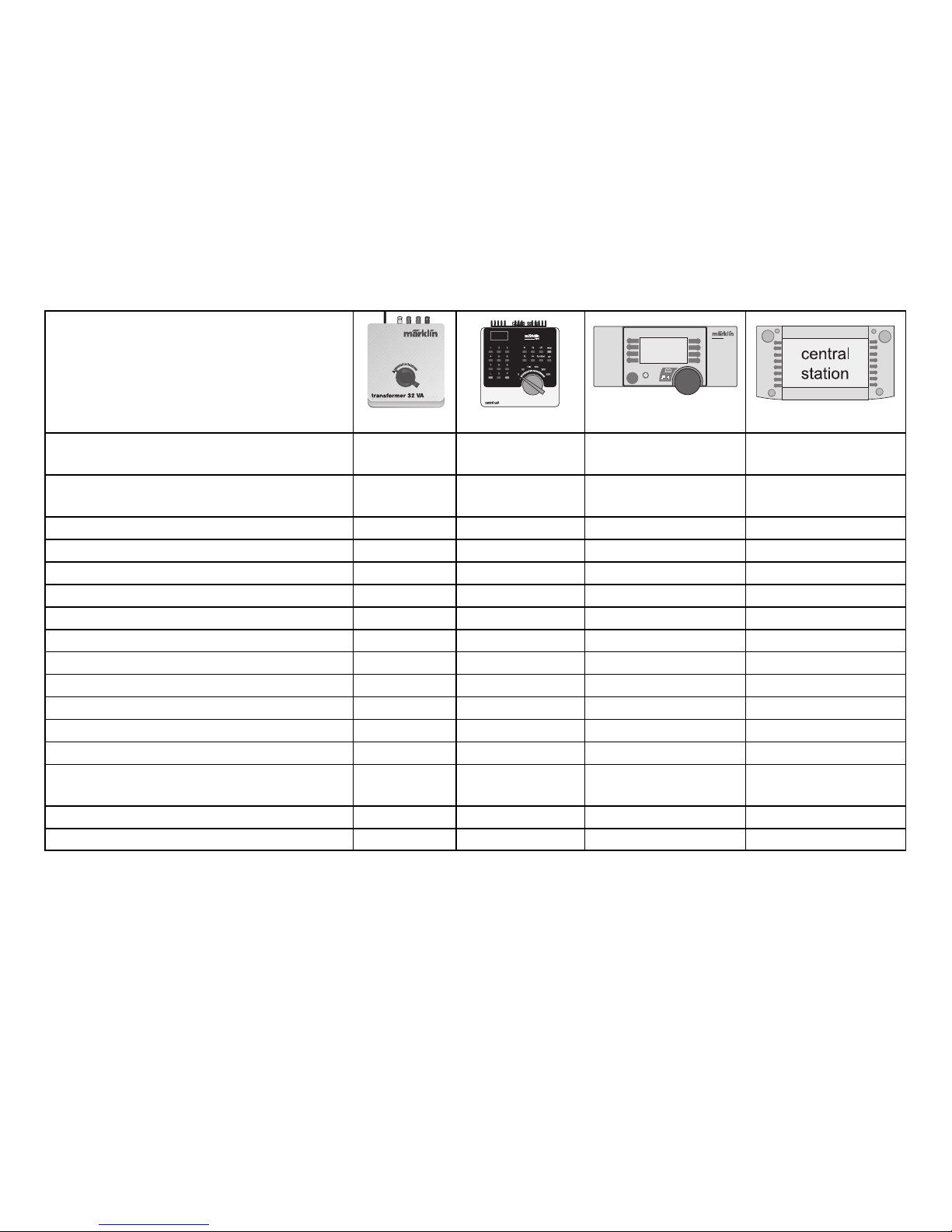
6647 6021 60652 60212
Headlight
1)
Always on2)40 / function+ off Headlight Button Headlight Button
Number Board Lights
1)
Always on2)40 / f1
3)
Button by Symbol Button by Symbol
Sound Effects of Steam Locomotive in Operation – 40 / f2
3)
Button by Symbol Button by Symbol
Sound Effects of Locomotive Whistle – 40 / f3
3)
Button by Symbol Button by Symbol
Low Speed Switching Range (only with ABV) – 40 / f4
3)
Button by Symbol Button by Symbol
Cab Lighting
1)
– 41 / f1
3)
Button by Symbol Button by Symbol
Sound Effects of Locomotive Bell – 41 / f2
3)
Button by Symbol Button by Symbol
Sound Effects: Whistle Pattern
– 41 / f3
3)
Button by Symbol Button by Symbol
Before Railroad Grade Crossing
Turning off the Sound Effects of Squealing Brakes – 41 / f4
3)
Button by Symbol Button by Symbol
Sound Effects: Air Pump – – – Button by Symbol
Sound Effects: Injector on/off – – – Button by Symbol
Sound Effects: Auxiliary Blower on/off – – – Button by Symbol
Sound Effects: Coupler disengaging/engaging – – – Button by Symbol
Sound Effects: Rail Joint (Frequency
– – – Button by Symbol
Depends on the Locomotive’s Speed)
Sound Effects: Blow Down with Compressed Air – – – Button by Symbol
Sound Effects: Cab Radio – – – Button by Symbol
STOP
STOP
mobile station
systems
1) => When the locomotive is operated with a Control Unit, Mobile Station, or Central Station, the sound effect
of a steam powered generator will also turned on at the same time.
2) => The brightness of the headlight and the number board lights depends of the level of voltage in the track.
3) => 40 = 1st address, 41 = 2nd address.
Page 6
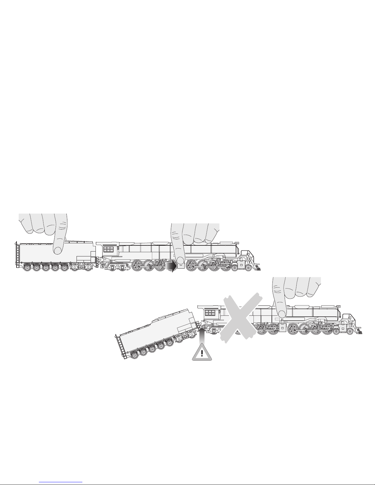
Caution! It is essential that you read
the following instructions before
using the locomotive on your model
railway system for the first time!
For safety reasons, this heavy and detailed model
is screwed to the supplied base. Please remove the
3 screws very carefully and keep them safe. When
moving the locomotive, transport it only on this base
and in the original case.
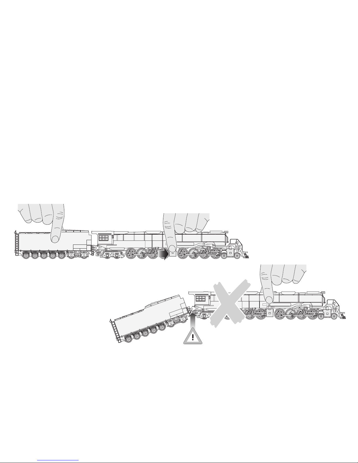
To avoid damaging any detail work, please handle
the model only at the places indicated.
The connection between the locomotive and the
tender must not be stretched or kinked.
6
Page 7

The extremely large locomotive places particular demands on your model railway system.
Before operating for the first time, please
check the following points in order to avoid
damage to the locomotive or your system:
● The usable minimum radius is 360 mm.
However, we recommend that you select greater
radii if at all possible (> 500 mm).
● The clearance profile of the locomotive is wider
and higher than the dimensions specified for
European model railways. Overhead cable masts
and signals must therefore be mounted as far
away from the centre of the rails as possible. Please pay attention to the signal drives, operating
levers or lanterns of the points drives which might
come into contact, depending on the installation
position. You must also take care with the tunnel
entrances, bridge handrails and platforms in the
vicinity of the bends in the sections.
● Points should be crossed at the appropriate speed.
This is particularly important for points with smaller
radii (up to 437.5 mm) and for curved sets of points.
● The locomotive has been designed primarily
for use with Märklin C-rails and K-rails. Contact
faults may occur in the event of very slow travel
on certain M-rails (curved points, three-way points).
● Crossings to inclines or gradients and transfer rails
(K-rail to C-rail or M-rail) should not be located
directly at the start of a bend. If necessary, move
the transfer point one rail length further away.
We recommend a careful test run with a second
person for assistance.
The maintenance work occurring under normal
operation is described below. For work on the
underneath of the engine, use the insert in the case
as a base. The heavy-duty motor and the drive
shafts require no maintenance. Please contact your
Märklin specialist for repairs and spare parts.
7
Page 8

Funktion
● Mögliche Betriebssysteme:
Märklin Transformer 6647, Märklin Delta,
Märklin Digital, Märklin Systems.
● Erkennung der Betriebsart: automatisch.
● Einstellbare Adresse (Control Unit): 01+02 bis 79+80
(Es werden immer Doppeladressen eingestellt).
Adresse ab Werk: 40+ 41.
● Mfx-Technologie für Mobile Station / Central Station.
● Veränderbare Anfahrverzögerung.
● Veränderbare Bremsverzögerung.
● Veränderbare Höchstgeschwindigkeit.
● Einstellen der Lokparameter elektronisch über
Control Unit, Mobile Station oder Central Station.
● Eingebaute Geräuschelektronik, nur im Betrieb
mit Control Unit oder Märklin Systems nutzbar.
Zusätzliche schaltbare Geräusche.
● Bis zu 2 Rauchgeneratoren nachrüstbar. Eingebaute
Rauchgeneratoren immer eingeschaltet. Rauchsätze zum Ändern der Lokparameter entfernen!
Jegliche Garantie-, Gewährleistungs- und Schadensersatzansprüche
sind ausgeschlossen, wenn in Märklin-Produkten nicht von Märklin
freigegebene Fremdteile eingebaut werden und / oder Märklin-Produkte
umgebaut werden und die eingebauten Fremdteile bzw. der Umbau
für sodann aufgetretene Mängel und / oder Schäden ursächlich war.
Die Darlegungs- und Beweislast dafür, dass der Einbau von Fremdteilen oder der Umbau in bzw. von Märklin-Produkten für aufgetretene
Mängel und / oder Schäden nicht ursächlich war, trägt die für den
Ein- und / oder Umbau verantwortliche Person und / oder Firma bzw.
der Kunde.
Sicherheitshinweise
● Die Lok darf nur mit einem dafür bestimmten
Betriebssystem (Märklin Wechselstrom-Transformator 6647, Märklin Delta, Märklin Digital oder
Märklin Systems) eingesetzt werden.
● Die Lok darf nur aus einer Leistungsquelle gleich-
zeitig versorgt werden.
● Beachten Sie unbedingt die Sicherheitshinweise in
der Gebrauchsanleitung zu Ihrem Betriebssystem.
8
Page 9
9
Schaltbare Funktionen
6647 6021 60652 60212
Stirnbeleuchtung
1)
Dauernd ein
2)
40 / function+ off Licht-Taste Licht-Taste
Nummernschilder-Beleuchtung
1)
Dauernd ein
2)
40 / f1
3)
Taste bei Symbol Taste bei Symbol
Geräusch: Dampf-Triebwerk – 40 / f2
3)
Taste bei Symbol Taste bei Symbol
Geräusch: Lokpfeife – 40 / f3
3)
Taste bei Symbol Taste bei Symbol
Rangiergang (nur ABV) – 40 / f4
3)
Taste bei Symbol Taste bei Symbol
Führerstandsbeleuchtung
1)
– 41 / f1
3)
Taste bei Symbol Taste bei Symbol
Geräusch: Lokglocke – 41 / f2
3)
Taste bei Symbol Taste bei Symbol
Geräusch: Pfeifsequenz vor Bahnübergang – 41 / f3
3)
Taste bei Symbol Taste bei Symbol
Geräusch: Bremsenquietschen abschalten – 41 / f4
3)
Taste bei Symbol Taste bei Symbol
Geräusch: Luftpumpe – – – Taste bei Symbol
Geräusch: Injektor ein/aus – – – Taste bei Symbol
Geräusch: Hilfsbläser ein/aus – – – Taste bei Symbol
Geräusch: Kupplung lösen / einrasten – – – Taste bei Symbol
Geräusch: Schienenstoß
– – – Taste bei Symbol
(Frequenz geschwindigkeitsunabhängig)
Geräusch: Abschlammen mit Preßluft – – – Taste bei Symbol
Geräusch: Kabinenfunk – – – Taste bei Symbol
STOP
STOP
mobile station
systems
1) => Bei Betrieb mit Control Unit, Mobile Station oder Central Station wird simultan auch das Geräusch einer
Dampflichtmaschine eingeschaltet.
2) => Intensität der Beleuchtung abhängig von der Höhe der Versorgungsspannung am Gleis.
3) => 40 = 1. Adresse, 41 = 2. Adresse.
Page 10
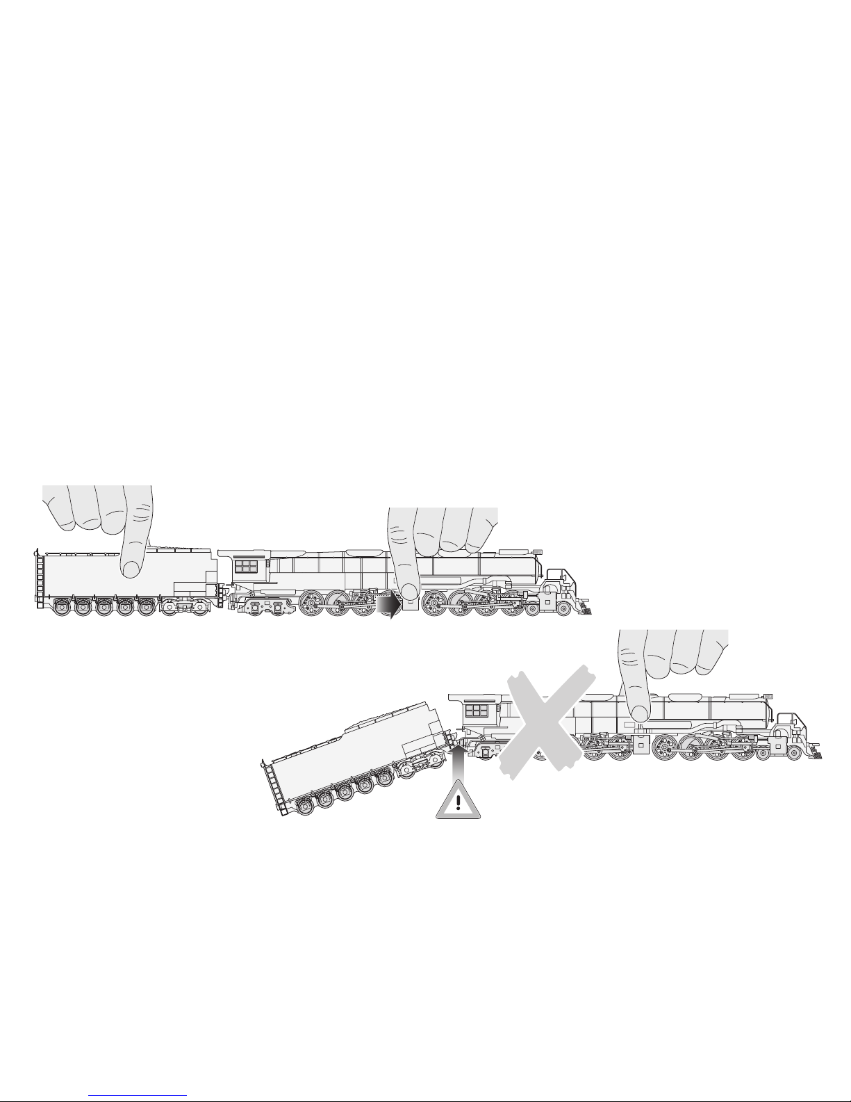
Vorsicht! Folgende Hinweise bitte
unbedingt vor dem ersten Einsatz
der Lokomotive auf Ihrer ModellbahnAnlage lesen!
Aus Sicherheitsgründen ist dieses schwere und
detaillierte Modell auf dem mitgelieferten Sockel
angeschraubt. Bitte entfernen Sie die 3 Schrauben
sehr vorsichtig und bewahren Sie sie auf. Bitte transportieren Sie die Lokomotive nur auf diesem Sockel
gesichert in der zugehörigen Originalkassette.
Bitte fassen Sie das Modell nur an den gezeigten
Stellen an, um keine Details zu beschädigen.
Die Verbindung zwischen Lok und Tender darf nicht
gedehnt oder geknickt werden.
10
Page 11

Die extrem große Lokomotive stellt besondere
Anforderungen an Ihre Modellbahnanlage.
Prüfen Sie vor der ersten Fahrt die folgenden
Punkte, um Beschädigungen an der Lok oder
an der Anlage zu vermeiden:
● Der befahrbare Mindestradius ist 360 mm.
Wir empfehlen jedoch möglichst größere Gleisradien (> 500 mm) zu wählen.
● Das Lichtraumprofil der Lokomotive ist breiter
und höher als die für europäische Modellbahnen
vorgegebenen Maße. Oberleitungsmasten und
Signale müssen daher möglichst weit vom
Schienenmittelpunkt montiert sein. Bitte achten
Sie auch auf Signalantriebe, Stellhebel oder Laternen an Weichenantrieben, die je nach Einbaulage
berührt werden können. Vorsicht auch bei Tunnelportalen, Brückengeländern und Bahnsteigen an
gebogenen Gleisabschnitten!
● Weichen sollten mit angemessener Geschwindig-
keit befahren werden. Dies gilt vor allem für Weichen
mit kleinen Radien (bis 437,5 mm) und für Bogenweichen.
● Die Lokomotive ist konstruktiv vorrangig für den
Betrieb mit Märklin C-Gleis und K-Gleis ausgelegt.
Bei sehr langsamer Fahrt auf bestimmten M-Gleisen
(Bogenweichen, Dreiwegweiche) können Kontaktstörungen auftreten.
● Übergänge zu Steigung oder Gefälle sowie
Übergangsgleise (K-Gleis zu C-Gleis oder M-Gleis)
sollen nicht direkt am Bogenanfang liegen. Falls
erforderlich, sollte der Übergang um eine Gleislänge verlegt werden.
Wir empfehlen eine vorsichtige Probefahrt mit einer
zweiten Person zur Unterstützung.
Die bei normalem Betrieb anfallenden Wartungsarbeiten sind nachfolgend beschrieben. Für Arbeiten
an der Unterseite der Lok dient der Einsatz in der
Kassette als Unterlage. Der Hochleistungsmotor und
die Antriebswellen sind wartungsfrei. Für Reparaturen
oder Ersatzteile wenden Sie sich bitte an Ihren
Märklin-Fachhändler.
11
Page 12

Fonction
● Systèmes d’exploitation possibles:
Märklin Transformer 6647, Märklin Delta,
Märklin Digital, Märklin Systems.
● Détection du mode d’exploitation: automatique.
● Adresses réglables (Control Unit): de 01+ 02
jusqu’à 79+ 80 (c’est toujours une double adresse
qui est encodée).
Adresse encodée en usine: 40+ 41.
● Technologie mfx pour Mobile Station /
Central Station.
● Temporisation d’accélération réglable.
● Temporisation de freinage réglable.
● Vitesse maximale réglable.
● Réglage des paramètres de la loco électronique-
ment à l’aide de la Control Unit, de la Mobile Station
ou de la Central Station.
● Bruiteur électronique intégré, utilisable unique-
ment lors d’exploitation avec la Control Unit ou
Märklin Systems. Bruitages complémentaires
commutables.
● Possibilité d’installer jusqu’à 2 générateurs fumi-
gènes. Générateurs fumigènes intégrés toujours
activés. Enlever les fumigènes pour modifier les
paramètres de la locomotive!
Tout recours à une garantie commerciale ou contractuelle ou à une
demande de dommages-intérêt est exclu si des pièces non autorisées
par Märklin sont intégrées dans les produits Märklin et / ou si les produits Märklin sont transformés et que les pièces d’autres fabricants
montées ou la transformation constituent la cause des défauts et / ou
dommages apparus. C’est à la personne et / ou la société responsable
du montage / de la transformation ou au client qu’incombe la charge
de prouver que le montage des pièces d’autres fabricants sur des
produits Märklin ou la transformation des produits Märklin n’est pas
à l’origine des défauts et ou dommages apparus.
Remarques importantes sur la sécurité
● La locomotive ne peut être mise en service
qu’avec un système d’exploitation adéquat
(Märklin courant alternatif- transformateur 6647,
Märklin Delta, Märklin Digital ou Märklin Systems).
● La locomotive ne peut être alimentée en courant
que par une seule source de courant.
● Veuillez impérativement respecter les remarques
sur la sécurité décrites dans le mode d’emploi en
ce qui concerne le système d’exploitation.
12
Page 13
13
Fonctions commutables
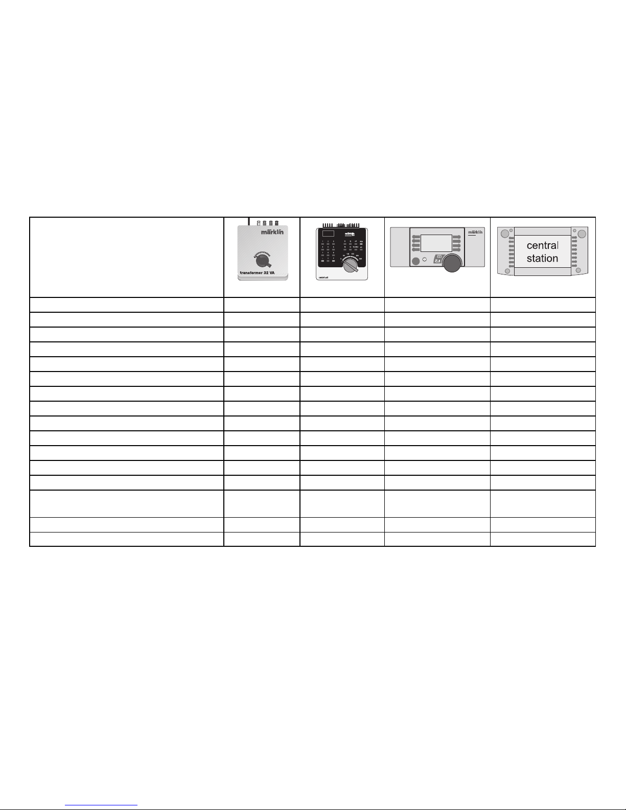
6647 6021 60652 60212
Eclairage feux de signalisation
1)
Activé en
40 / function+ off Touche éclairage feux Touche éclairage feux
permanence
2)
Eclairage panneaux d’immatriculation
1)
Activé en
40 / f1
3)
Touche à côté symbole Touche à côté symbole
permanence
2)
Bruitage mécanisme moteur à vapeur – 40 / f2
3)
Touche à côté symbole Touche à côté symbole
Bruitage sifflet locomotive – 40 / f3
3)
Touche à côté symbole Touche à côté symbole
Mode manœuvre (seulement Temp. Acc. Fr) – 40 / f4
3)
Touche à côté symbole Touche à côté symbole
Eclairage poste de conduite
1)
– 41 / f1
3)
Touche à côté symbole Touche à côté symbole
Bruitage cloche locomotive – 41 / f2
3)
Touche à côté symbole Touche à côté symbole
Bruitage séquence sifflet avant passage à niveau – 41 / f3
3)
Touche à côté symbole Touche à côté symbole
Désactivation bruitage crissement de freins – 41 / f4
3)
Touche à côté symbole Touche à côté symbole
Bruitage compresseur – – – Touche à côté symbole
Bruitage injecteur on/off – – – Touche à côté symbole
Bruitage souffleur auxiliaire on/off – – – Touche à côté symbole
Bruitage dételage / attelage – – – Touche à côté symbole
Bruitage joints de rails
– – – Touche à côté symbole
(fréquence dépendant de la vitesse)
Bruitage purge avec air comprimé – – – Touche à côté symbole
Bruitage radio cabine – – – Touche à côté symbole
STOP
STOP
mobile station
systems
1) => En exploitation avec Control Unit, Mobile Station ou Central Station, le bruitage d’une dynamo d’éclairage
est activé simultanément.
2) => L’intensité de l’éclairage est dépendante de la tension d’alimentation appliquée à la voie.
3) => 40 = 1. Adresse, 41 = 2. Adresse.
Page 14
Attention! Veuillez lire impérativement
les recommandations suivantes avant
de mettre la locomotive en service
pour la première fois sur votre réseau
ferroviaire réduit!
Pour des raisons de sécurité, ce modèle lourd et
pourvu de nombreux détails est livré vissé sur un
socle. Retirez les 3 vis, avec la précaution qui s’impose et conservez-les. Ne transportez la locomotive
que vissée sur ce socle et rangée dans la cassette
d’origine correspondante.
Ne saisissez le modèle qu’aux endroits indiqués pour
éviter tout endommagement des détails. La liaison
entre la locomotive et le tender ne doit être
ni étirée, ni coudée
14
Page 15

Cette locomotive extrêmement grosse pose
des exigences particulières à votre réseau
ferroviaire réduit. Pour éviter tout endommagement de la locomotive ou de l’installation,
vérifiez les points suivants avant la première
mise en route:
● Le rayon minimum de déplacement est de 360 mm.
Nous recommandons cependant de choisir,
si possible, des rayons de voie plus importants
(> 500 mm).
● Le gabarit d’espace libre de la locomotive est plus
large et plus haut que celui des cotes prescrites
pour les réseaux ferroviaires réduits européens.
Les poteaux de caténaires et les signaux doivent
donc être montés aussi loin que possible de l’axe
des rails. Faites également attention aux entraînements de signaux, leviers ou pylônes d’éclairage
sur les systèmes d’entraînement d’aiguillages, car
ils risquent d’être touchés suivant leur position de
montage. Faire également attention aux portiques
de tunnels, parapets de ponts et aux quais, au
niveau des tronçons de voies coudées !
● N’aborder les aiguillages qu’avec une vitesse
mesurée. Ceci est particulièrement valable pour
les aiguillages à petit rayon (jusqu’à 437,5 mm)
et pour les aiguillages courbes.
● La locomotive est construite de prime abord pour
fonctionner sur les rails C et K de Märklin. Des
défauts de contact peuvent se produire à vitesse
très lente sur certains rails M (aiguillages courbes,
aiguillages à trois voies).
● Les transitions de montées ou de pentes ainsi
que les rails de transition (entre rails K et C ou M)
ne doivent pas se trouver directement au début
de la courbe. Si nécessaire, décaler la transition
d’une longueur de rail.
Nous recommandons de faire un essai de parcours
prudent avec l’assistance d’une deuxième personne.
Les opérations de maintenance nécessaires dans
le cas d’un fonctionnement normal sont décrites
ci-après. Pour les opérations à effectuer sur la partie
inférieure de la locomotive, utiliser la garniture placée
dans la cassette en tant que support. Le moteur très
performant ainsi que les arbres d’entraînement sont
exempts de maintenance. En cas de réparation ou
pour les pièces de rechange, veuillez contacter votre
commerçant spécialisé Märklin.
15
Page 16

Werking
● Mogelijke bedrijfssystemen:
Märklin Transformer 6647, Märklin Delta,
Märklin Digital, Märklin Systems.
● Herkenning van het bedrijfssysteem: automatisch.
● Instelbaar adres (Control Unit): 01+ 02 t/m 79+80
(er worden altijd dubbele adressen ingesteld).
Vanaf de fabriek: 40+ 41.
● Mfx-technologie voor het Mobile Station /
Central Station.
● Instelbare optrekvertraging.
● Instelbare afremvertraging.
● Instelbare maximumsnelheid.
● Elektronische instelling van de locomotiefpara-
meters via de Control Unit, Mobile Station of
Central Station.
● Ingebouwde geluidselektronica, alleen bruikbaar in
het bedrijf met de Control Unit of Märklin Systems.
Extra schakelbare geluiden.
● Er kunnen 2 rookgeneratoren ingebouwd worden.
Ingebouwde rookgeneratoren zijn altijd ingeschakeld. Rookgeneratoren voor het wijzigen van de
locparameters verwijderen.
Elke aanspraak op garantie en schadevergoeding is uitgesloten, wanneer in Märklin-producten niet door Märklin vrijgegeven vreemde
onderdelen ingebouwd en / of Märklin-producten omgebouwd worden
en de ingebouwde vreemde onderdelen resp. de ombouw oorzaak
van nadien opgetreden defecten en / of schade was. De aantoonplicht
en de bewijslijst daaromtrent, dat de inbouw van vreemde onderdelen
in Märklin-producten of de ombouw van Märklin-producten niet de
oorzaak van opgetreden defecten en / of schade is geweest, berust bij
de voor de inbouw en/of ombouw verantwoordelijke persoon en / of
firma danwel bij de klant.
Veiligheidsvoorschriften
● De loc mag alleen met een daarvoor bestemd
bedrjfssysteem (Märklin wisselstroom transformator 6647, Märklin Delta, Märklin digitaal
of Märklin Systems) gebruikt worden.
● De loc mag niet vanuit meer dan één stroom-
voorziening gelijktijdig gevoed worden.
● Lees ook aandachtig de veiligheidsvoorschriften
in de gebruiksaanwijzing van uw bedrijfssysteem.
16
Page 17
17
Schakelbare functies
6647 6021 60652 60212
Frontverlichting
1)
Continu aan
2)
40 / function+ off Verlichtingstoets Verlichtingstoets
Nummerplaat-verlichting
1)
Continu aan
2)
40 / f1
3)
Toets bij het symbool Toets bij het symbool
Geluid stoom aandrijving – 40 / f2
3)
Toets bij het symbool Toets bij het symbool
Geluid locfluit – 40 / f3
3)
Toets bij het symbool Toets bij het symbool
Rangeerstand alleen optrek- afremvertaging – 40 / f4
3)
Toets bij het symbool Toets bij het symbool
Cabine verlichting
1)
– 41 / f1
3)
Toets bij het symbool Toets bij het symbool
Geluid van luidklok – 41 / f2
3)
Toets bij het symbool Toets bij het symbool
Geluid van fluitsignaal voor overweg – 41 / f3
3)
Toets bij het symbool Toets bij het symbool
Geluid van piepende remmen uitschakelen – 41 / f4
3)
Toets bij het symbool Toets bij het symbool
Geluid: luchtpomp – – – Toets bij het symbool
Geluid: injecteur aan/uit – – – Toets bij het symbool
Geluid: hulpventilator aan/uit – – – Toets bij het symbool
Geluid: lossen en aankoppelen van koppeling – – – Toets bij het symbool
Geluid: raillasovergangen
–– –
Toets bij het symbool
(frequentie is onafhankelijk van de snelheid)
Geluid: roet blazen met perslucht – – – Toets bij het symbool
Geluid: cabine radioverbinding – – – Toets bij het symbool
STOP
STOP
mobile station
systems
1) => Bij het bedrijf met Control Unit, Mobile Station of Central Station wordt simultaan ook het geluid van de
stoom-lichtmachine ingeschakeld.
2) => Intensiteit van de verlichting is afhankelijk van de hoogte van de voedingsspanning op de rails.
3) => 40 = eerste adres, 41 = tweede adres.
Page 18
Voorzichtig! De volgende aanwijzingen
beslist lezen voordat u de locomotief
voor het eerst op uw modelbaan
laat lopen!
Om veiligheidsredenen is dit zware en gedetailleerde
model op de bijgeleverde sokkel vastgeschroefd.
Verwijder de 3 schroeven voorzichtig en bewaar
deze zorgvuldig. Transporteer de locomotief uitsluitend in geborgde toestand, d.w.z. vastgezet op
de sokkel, in de bijbehorende
originele cassette.
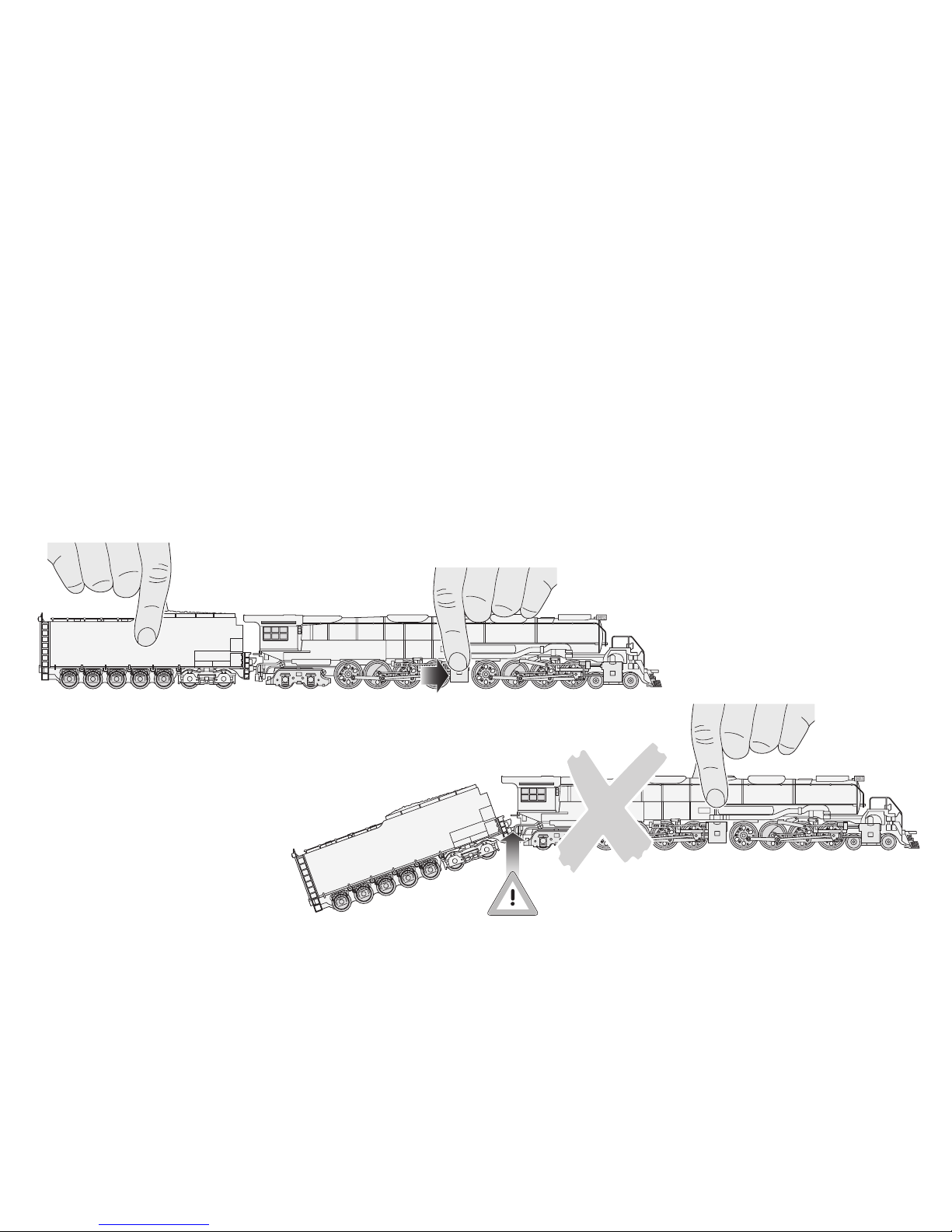
Pak het model uitsluitend op de gemarkeerde
punten beet, om geen details te beschadigen.
De verbinding tussen loc en tender mag niet uitgerekt of geknikt worden.
18
Page 19

De extreem grote locomotief stelt bijzondere
eisen aan uw modelbaan. Controleer voorafgaand aan de eerste rit de volgende punten,
om beschadigingen aan de loc of de baan te
voorkomen:
● De berijdbare minimum radius bedraagt 360 mm.
Wij adviseren echter, de railradiussen zo groot
mogelijk (> 500 mm) te kiezen.
● Het profiel van vrije ruimte is bij deze locomotief
breder en hoger dan de voor Europese modelbanen
vastgestelde afmetingen. Bovenleidingmasten en
seinen dienen om die reden zo ver mogelijk van
het railmiddelpunt te zijn gemonteerd. Let tevens
op de signaalaandrijvingen, wisselhandels of lantaarns op wisselaandrijvingen, die al naar gelang
de inbouwpositie kunnen worden geraakt. Wees
tevens voorzichtig bij tunnelportalen, brugbalustrades en perrons langs gebogen railstukken!
● Het rijden over wissels dient met aangepaste
snelheid te geschieden. Dit geldt met name voor
wissels met kleine radiussen (tot 437,5 mm) en
voor meegebogen wissels.
● De locomotief is constructief primair voor gebruik
met Märklin C-rails en K-rails ontworpen. Bij zeer
langzaam rijden op bepaalde M-rails (meegebogen
wissel, driewegwissel) kunnen contactstoringen
optreden.
● Overgangen op steigingen of dalingen en op over-
gangsrails (K-rails op C-rails of M-rails) dienen niet
direct bij een gebogen railstuk te beginnen. Indien
noodzakelijk, moet de overgang één railstuklengte
verder worden geprojecteerd.
Wij adviseren een voorzichtige proefrit te maken,
liefst met een tweede persoon voor assistentie.
De bij normaal bedrijf noodzakelijke onderhoudswerkzaamheden staan hierna beschreven. Voor
werkzaamheden aan de onderkant van de loc dient
het inzetstuk in de cassete als steun. De hoogvermogen-motor en de aandrijfassen zijn onderhoudsvrij. Voor reparaties of onderdelen gelieve u contact
op te nemen met uw Märklin-dealer.
19
Page 20

Función
● Sistemas operativos posibles:
Märklin transformador 6647, Märklin Delta,
Märklin Digital, Märklin Systems.
● Reconocimiento del sistema: automático.
● Dirección ajustable (Control Unit): 01+ 02 hasta
79+ 80 (se ajustarán siempre dos direcciones).
Código de fábrica: 40+ 41.
● Tecnología mfx para la Mobile Station /
Central Station.
● Arranque lento variable.
● Frenado lento variable.
● Velocidad máxima variable.
● Fijar parámetros de la locomotora electrónica-
mente por el Control Unit, Mobile Station o
Central Station.
● Electrónica incorporada de ruidos: solo útil en fun-
cionamiento con Control Unit o Märklin Systems.
Ruidos suplementarios gobernables.
● Reequipable hasta con 2 generadores de humo.
Los generadores de humo están siempre conectados. Para modificar los parámetros de la locomotora es necesario retirar los conjuntos de humo.
Se excluye todo derecho de garantía, prestación de garantía e indemnización sobre aquellos productos Märklin en los que se hubieran
montado piezas ajenas no autorizadas por Märklin y/o sobre aquellos
productos Märklin que hayan sido modificados cuando la piezas ajenas
montadas o la modificación sean las causas de los desperfectos y/o
daños posteriormente surgidos. La persona y/o empresa o el cliente
responsable del montaje o modificación será el responsable de probar
y alegar que el montaje de piezas ajenas o la modificación en/de
productos Märklin no son las causas de los desperfectos y/o daños
surgidos.
Aviso de seguridad
● La locomotora solamente debe funcionar en un
sistema de corriente propio (Märklin corriente
alterna – transformador 6647 – Märklin Delta –
Märklin Digital o Märklin Systems).
● La locomotora no deberá recibir corriente eléctrica
mas que de un solo punto de abasto.
● Observe bajo todos los conceptos, las medidas
de seguridad indicadas en las instrucciones de
su sistema de funcionamiento.
20
Page 21
21
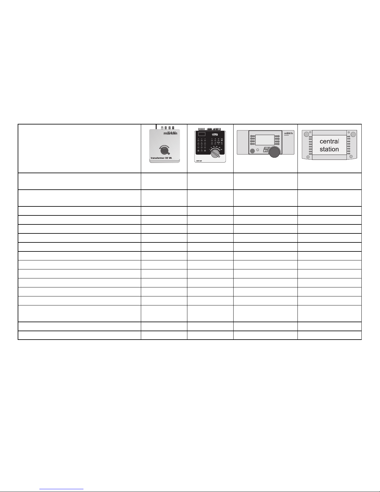
Funciones posibles
6647 6021 60652 60212
Iluminación frontal
1)
Encendida de 40 /
Tecla de luz Tecla de luz
forma continua 2)función+ off
Iluminación de las matrículas
1)
Encendida de
40 / f1
3)
Tecla con símbolo Tecla con símbolo
forma continua
2)
Sonido de motores de vapor – 40 / f2
3)
Tecla con símbolo Tecla con símbolo
Sonido del silbido de la locomotora – 40 / f3
3)
Tecla con símbolo Tecla con símbolo
Marcha de maniobra (sólo ABV) – 40 / f4
3)
Tecla con símbolo Tecla con símbolo
Iluminación del puesto de maquinista
1)
– 41 / f1
3)
Tecla con símbolo Tecla con símbolo
Sonido de la campana de la locomotora – 41 / f2
3)
Tecla con símbolo Tecla con símbolo
Sonido: secuencia de silbidos del paso a nivel – 41 / f3
3)
Tecla con símbolo Tecla con símbolo
Desconectar el sonido del chirrido de los frenos – 41 / f4
3)
Tecla con símbolo Tecla con símbolo
Sonido: bomba de aire – – – Tecla con símbolo
Sonido: Inyector on/off – – – Tecla con símbolo
Sonido: Soplador auxiliar on/off – – – Tecla con símbolo
Sonido: soltar / enganchar acoplamiento – – – Tecla con símbolo
Sonido: junta de carril (independientemente
– – – Tecla con símbolo
de la velocidad de frecuencia)
Sonido: eliminar el barro con aire comprimido – – – Tecla con símbolo
Sonido: radio de cabina – – – Tecla con símbolo
STOP
STOP
mobile station
systems
1) => En funcionamiento con Control Unit, Mobile Station o Central Station se conectará también de forma
simultánea el sonido de un alternador de vapor.
2) => La intensidad de la iluminación dependerá de la tensión suministrada a la vía.
3) => 40 = 1
a
dirección, 41 = 2adirección
Page 22
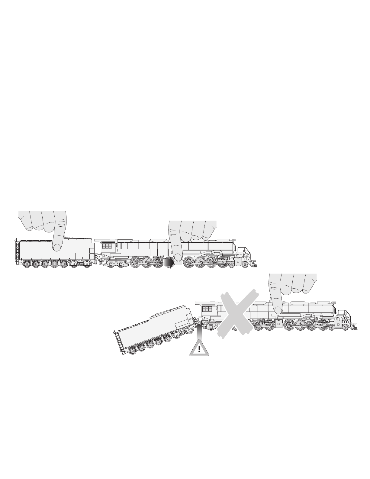
¡Precaución! ¡Es imprescindible que
lea las siguientes indicaciones antes
de utilizar la locomotora por primera
vez en su instalación de maqueta
de tren!
Por cuestiones de seguridad, este modelo pesado
y detallado viene atornillado en el zócalo que se
suministra adjunto. Retire los 3 tornillos con mucho
cuidado y guárdelos. Para transportar la locomotora,
hágalo sólo asegurada en este zócalo en el estuche
original pertinente.
Tome el modelo sólo por los lugares indicados,
sin dañar ningún detalle. El enganche entre la locomotora y el ténder no debe estirarse ni doblarse.
22
Page 23

La locomotora de gran tamaño exige que su
instalación de maqueta de tren cumpla unos
requisitos especiales. Compruebe los siguientes
puntos antes del primer viaje con el fin de
evitar que se produzcan desperfectos en la
locomotora o en la instalación:
● El radio mínimo transitable es de 360 mm.
No obstante, recomendamos elegir, en lo posible,
radios de vía más grandes (> 500 mm).
● El gálibo de paso libre de la locomotora es más
ancho y más alto que los gálibos para las medidas
prefijadas de los trenes de maqueta europeos.
Por ello, los postes de la línea eléctrica aérea y las
señales deben montarse lo más lejos posible del
centro de las vías. Asimismo, preste atención a
los accionamientos de las señales, a las palancas
de maniobra o a los faroles que hay junto a los
aparatos de maniobra y que puedan rozarse
según la posición de instalación. ¡Tenga también
cuidado con las bocas de túneles, las barandillas
de puentes y los andenes que hay junto a los
tramos de vía en curva!
● Por las agujas se deberá circular con una velocidad
adecuada. Esto es válido sobre todo para agujas
con radios pequeños (hasta 437,5 mm) y para
agujas curvas.
● La locomotora se ha diseñado con prioridad
constructiva para el funcionamiento con vía C y
vía K de Märklin. En una marcha muy lenta sobre
determinadas vías M (agujas curvas, agujas de
tres vías) pueden surgir problemas de contacto.
● Las transiciones a cuestas o declives, así como
las vías de transición (vía K a vía C o vía M) no
deben encontrarse directamente en el inicio de
la curva. Si fuera necesario, se deberá trasladar
la transición en una longitud de vía.
Recomendamos realizar con cuidado un viaje de
prueba con una segunda persona que le ayude.
A continuación se describen los trabajos de mantenimiento necesarios en funcionamiento normal. Para
realizar trabajos en la parte inferior de la locomotora,
la pieza insertada en el estuche sirve de base. El
motor de gran potencia y los árboles de accionamiento no requieren mantenimiento. Para reparaciones o piezas de repuesto, diríjase a su comerciante
especializado de Märklin.
23
Page 24

Funzionamento
● Possibili sistemi di funzionamento:
Märklin Transformer 6647, Märklin Delta,
Märklin Digital, Märklin Systems.
● Riconoscimento del tipo di funzionamento:
automatico.
● Indirizzi impostabili (Control Unit): 01+ 02 sino
a 79+ 80 (vengono sempre impostati degli
indirizzi doppi).
Indirizzo di fabbrica: 40 + 41.
● Tecnologia Mfx per Mobile Station / Central Station.
● Ritardo di avviamento modificabile.
● Ritardo di frenatura modificabile.
● Velocità massima modificabile.
● Regolazione dei parametri della locomotiva elet-
tronicamente tramite Control Unit, Mobile Station
oppure Central Station.
● Generatore elettronico di suoni incorporato,
utilizzabile soltanto nel funzionamento con
Control Unit oppure Märklin Systems.
Suoni aggiuntivi commutabili.
● Sino a 2 generatori di fumo equipaggiabili in
seguito. Generatori di fumo incorporati sempre
attivati. Rimuovere gli apparati fumogeni per la
modifica dei parametri della locomotiva!
Märklin non fornisce alcuna garanzia, assicurazione e risarcimento
danni in caso di montaggio sui prodotti Märklin di componenti non
espressamente approvati dalla ditta. Märklin altresì non risponde in
caso di modifiche al prodotto, qualora i difetti e i danni riscontrati sullo
stesso siano stati causati da modifiche non autorizzate o dal montaggio di componente esterni da lei non approvati. L'onere della prova
che i componenti montati e le modifiche apportate non sono state la
causa del danno o del difetto, resta a carico del cliente o della persona /
ditta che ha effettuato il montaggio di componenti estranei o che ha
apportato modifiche non autorizzate.
Avvertenze per la sicurezza
● Tale locomotiva deve essere impiegata soltanto con
un sistema di funzionamento adeguato per questa
(trasformatore per corrente alternata Märklin 6647,
Märklin Delta, Märklin Digital oppure Märklin Systems).
● La locomotiva non deve venire alimentata nello
stesso tempo con più di una sorgente di potenza.
● Vogliate prestare assolutamente attenzione alle
avvertenze di sicurezza nelle istruzioni di impiego
per il Vostro sistema di funzionamento.
24
Page 25
25
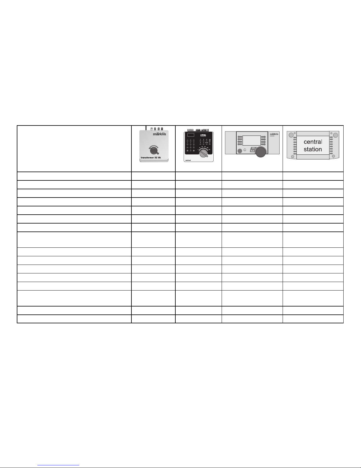
Funzioni commutabili
6647 6021 60652 60212
Illuminazione di testa
1)
Sempre accesa2)40 / function+ off Tasto illuminazione Tasto illuminazione
Illuminazione tabelle numeriche
1)
Sempre accesa2)40 / f1
3)
Tasto accanto al simbolo Tasto accanto al simbolo
Rumori del motore a vapore – 40 / f2
3)
Tasto accanto al simbolo Tasto accanto al simbolo
Suono del fischio da locomotiva – 40 / f3
3)
Tasto accanto al simbolo Tasto accanto al simbolo
Andatura da manovra (solo ABV) – 40 / f4
3)
Tasto accanto al simbolo Tasto accanto al simbolo
Illuminazione della cabina di guida
1)
– 41 / f1
3)
Tasto accanto al simbolo Tasto accanto al simbolo
Suono della campana da locomotiva – 41 / f2
3)
Tasto accanto al simbolo Tasto accanto al simbolo
Suono: sequenza di fischi prima
– 41 / f3
3)
Tasto accanto al simbolo Tasto accanto al simbolo
di un passaggio a livello
Esclusione del rumore di stridore dei freni – 41 / f4
3)
Tasto accanto al simbolo Tasto accanto al simbolo
Rumore: compressore dell’aria – – – Tasto accanto al simbolo
Rumore: iniettore attivo/spento – – – Tasto accanto al simbolo
Rumore: soffiante ausiliario attivo/spento – – – Tasto accanto al simbolo
Rumore: agganciamento sganciato / innestato – – – Tasto accanto al simbolo
Rumore: battito sulle rotaie
– – – Tasto accanto al simbolo
(Frequenza indipendente dalla velocità)
Rumore: scaricatore di scorie ad aria compressa – – – Tasto accanto al simbolo
Rumore: radio nella cabina – – – Tasto accanto al simbolo
STOP
STOP
mobile station
systems
1) => In caso di funzionamento con Control Unit, Mobile Station oppure Central Station viene attivato
simultaneamente anche il rumore di un generatore elettrico a vapore.
2) => Intensità dell’illuminazione dipendente dal livello della tensione di alimentazione sul binario.
3) => 40 = 1° indirizzo, 41 = 2° indirizzo.
Page 26
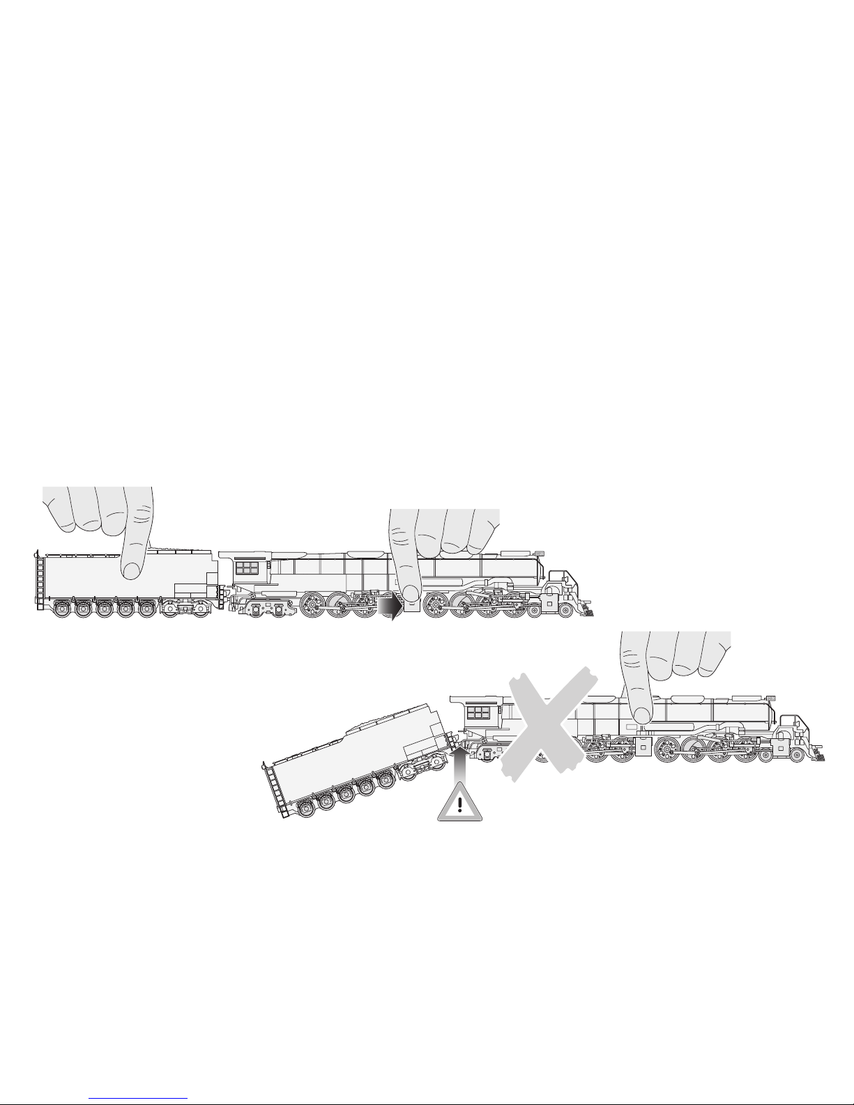
Cautela! Si prega di leggere attentamente le seguenti avvertenze prima
del primo impiego della locomotiva
sull'impianto!
Per motivi di sicurezza, questo pesante e dettagliato
modello è avvitato sullo zoccolo fornito in dotazione.
Svitare le 3 viti con estrema cautela e conservarle.
Trasportare la locomotiva protetta su questo zoccolo
e nella relativa cassetta originale.
Afferrare il modello solo sui punti indicati per non
danneggiare i dettagli. Il collegamento tra la locomotiva ed il tender non deve essere ruotato o piegato.
26
Page 27

La locomotiva estremamente grande richiede
caratteristiche particolari dell'impianto.
Per evitare di danneggiare la locomotiva o
l'impianto, prima della prima marcia controllare
i seguenti punti:
● Il raggio minimo percorribile è di 360 mm;
suggeriamo tuttavia di scegliere, se possibile,
raggi maggiori (> 500 mm) dei binari.
● La sagoma limite della locomotiva è più larga e più
alta delle quote assegnate per le ferrovie in miniatura europee; i pali della linea di contatto aerea ed
i segnali devono essere quindi montati alla maggior
distanza possibile dalla linea media del binario;
si prega di prestare attenzione ai sistemi di azionamento dei segnali, alle leve degli scambi o alle
lanterne sui sistemi di azionamento degli scambi
che, a seconda della posizione di montaggio,
possono essere toccate; cautela anche nei portali
di tunnel, ringhiere di ponti e marciapiedi su tratti
a binario curvo.
● Occorre percorrere gli scambi con una velocità
adeguata; ciò vale in primo luogo per gli scambi di
piccolo raggio (fino a 437,5 mm) e per gli scambi
in curva.
● La locomotiva è stata dimensionata costruttiva-
mente per il funzionamento con binari C e K
Märklin; in caso di marcia molto lenta su determinati binari M (scambi in curva, scambio a tre vie)
si possono verificare anomalie di contatto.
● Le transizioni su tratti in salita o in discesa ed i
binari di raccordo (binario K su binario C o binario
M) non devono essere direttamente all'inizio della
curva; se necessario, la transizione deve essere
spostata di una lunghezza di binario.
Suggeriamo di eseguire con cautela una marcia
di prova insieme ad una seconda persona.
I lavori di manutenzione necessario per il funzionamento normale sono descritti qui di seguito. Per i
lavori sul lato inferiore della locomotiva, la base di
appoggio è costituita dall'attacco nella cassetta.
Il motore di alta potenza e gli alberi di azionamento
sono esenti da manutenzione. Per riparazione o
pezzi di ricambio si prega di rivolgersi al proprio
rivenditore specializzato Märklin.
27
Page 28

Funktion
● Möjliga driftsystem: Märklin Transformer 6647,
Märklin Delta, Märklin Digital, Märklin Systems.
● Driftsättet igenkänns automatiskt.
● Inställbar adress (Conrol Unit): 01+ 02 till 79 +80
(det ställs alltid in dubbla adresser).
Adress från tillverkaren: 40+ 41.
● Mfx-teknologi för Mobile Station / Central Station.
● Accelerationsfördröjning kan ändras.
● Bromsfördröjning kan ändras.
● Toppfart kan ändras.
● Elektronisk inställning av lokparametrar via
Control Unit, Mobile Station eller Central Station.
● Inbyggd ljudelektronik kan endast användas vid
drift med Control Unit eller Märklin Systems.
Ytterligare ljud kan kopplas.
● Kan efteråt förses med max två rökgeneratorer.
Inmonterade rökgeneratorer är alltid på. Ta bort
röksatser före ändring av lokparametrar!
Varje form av anspråk på garanti och skadestånd är utesluten om
delar används i Märklin-produkter som inte har godkänts av Märklin
och / eller om Märklin-produkter har modifierats och de inbyggda
främmande delarna resp. modifieringen var upphov till de därefter
uppträdande felen och / eller skadorna. Bevisbördan för att inbyggnaden av främmande delar i eller ombyggnaden av Märklin-produkter
inte är upphovet till de uppträdande felen och / eller skadorna, bär den
person och / eller företag resp. kund som är ansvarig för in- och / eller
ombyggnaden.
Säkerhetsanvisningar
● Loket får endast köras med ett därtill avsett drift-
system (Märklin Växelström-transformator 6647,
Märklin Delta, Märklin Digital eller Märklin Systems).
● Loket får inte samtidigt försörjas av mer än en
kraftkälla.
● Beakta alltid säkerhetsanvisningarna i bruksanvis-
ningen som hör till respektive driftsystemet.
28
Page 29
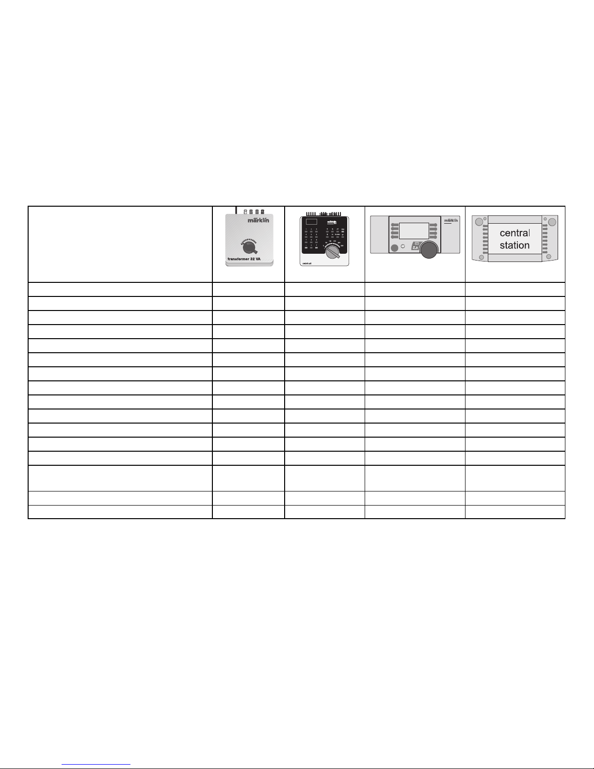
29
Kopplingsbara funktioner
6647 6021 60652 60212
Frontbelysning
1)
Permanent till2)40 / function+ off Ljustangent Ljustangent
Nummerplåtsbelysning
1)
Permanent till2)40 / f1
3)
Tangent vid symbol Tangent vid symbol
Ljud ångmaskin – 40 / f2
3)
Tangent vid symbol Tangent vid symbol
Ljud lokvissla – 40 / f3
3)
Tangent vid symbol Tangent vid symbol
Rangergång (endast ABV) – 40 / f4
3)
Tangent vid symbol Tangent vid symbol
Förarhyttsbelysning
1)
– 41 / f1
3)
Tangent vid symbol Tangent vid symbol
Ljud lokklocka – 41 / f2
3)
Tangent vid symbol Tangent vid symbol
Ljud: visselsekvens före järnvägsövergång – 41 / f3
3)
Tangent vid symbol Tangent vid symbol
Ljud bromsgnissel stäng av – 41 / f4
3)
Tangent vid symbol Tangent vid symbol
Ljud: luftpump – – – Tangent vid symbol
Ljud: injektor till/från – – – Tangent vid symbol
Ljud: reservfläkt till/från – – – Tangent vid symbol
Ljud: kopplet lossas / kopplas till – – – Tangent vid symbol
Ljud: skenskarv
– – – Tangent vid symbol
(frekvens hastighetsoberoende)
Ljud: slamma med tryckluft – – – Tangent vid symbol
Ljud: hyttradio – – – Tangent vid symbol
STOP
STOP
mobile station
systems
1) => Vid drift med Control Unit, Mobile Station eller Central Station kopplas samtidigt även ljudet för en ångljusmaskin till.
2) => Belysningens intensitet beror på försörjningsspänning i rälsen.
3) => 40 = 1 adress, 41 = 2 adress.
Page 30
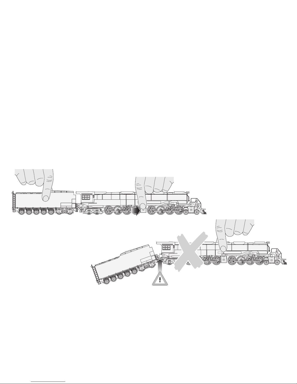
Se upp! Följande hänvisningar måste
du absolut läsa innan du tar loket i
drift för första gången på din modelljärnväg!
Av säkerhetsskäl är denna tunga och detaljerade
modell fastskruvad på den medlevererade sockeln.
Var vänlig demontera de 3 skruvarna mycket försiktigt och spara dem. Vi ber dig att alltid transportera
loket fastsatt i tillhörande originalkassett efter att det
satts fast på denna sockel.
Vi ber dig att endast fatta tag i modellen på de
ställen som visas, för att inga detaljer ska skadas.
Förbindningen mellan lok och tender får inte töjas
eller böjas.
30
Page 31

Det extremt stora loket ställer speciella krav
på din modelljärnväg. Kontrollera följande
punkter innan du kör det för första gången,
för att förhindra att skador uppstår på lok eller
anläggning:
● Användbar minsta kurvradie är 360 mm.
Vi rekommenderar dock att välja kurvradierna
så stora som möjligt (> 500 mm).
● Lokets frontprofil är bredare och högre än vad
som är fastställt mått för europeiska modelljärnvägar. Ledningsstolpar och signaler måste därför
vara monterade så långt bort som möjligt från
rälsens mittlinje. Se även upp med signalmotorer,
växelhävstänger och lampor vid växelmotorer,
vilka kan beröras beroende på hur de är monterade.
Se även upp vid tunnelingångar, broräcken och
perronger i krökta rälsavsnitt!
● Kör igenom växlarna med anpassad hastighet.
Detta gäller framför allt för växlar med liten radie
(upp till 437,5 mm) och för kurvväxlar.
● Loket är i första hand konstruerat för användning
på Märklin C-räls och K-räls. Vid mycket långsam
fart på viss M-räls (kurvväxlar, 3-vägsväxlar) kan
kontaktstörningar uppträda.
● Övergångar till stigningar eller nerförsbackar samt
övergångsräls (K-räls till C-räls eller M-räls) bör
inte ligga direkt vid kurvans början. Om så krävs
bör övergången förläggas med en rälslängd.
Vi rekommenderar en försiktig testfart med en andra
person som hjälp.
De servicearbeten som ska utföras vid normal drift
beskrivs nedan. Vid arbeten på lokets undersida
tjänstgör insatsen i kassetten som underlag.
Högeffektmotorn och drivaxlarna är underhållsfria.
För reparationer eller reservdelar ber vi dig kontakta
din Märklin-återförsäljare.
31
Page 32

Funktion
● Mulige driftssystemer: Märklin Transformer 6647,
Märklin Delta, Märklin Digital, Märklin Systems.
● Registrering af driftsarten: automatisk.
● Indstillelig adresse (Control Unit): 01+ 02 til 79 +80
(der indstilles altid dobbeltadresser).
Adresse ab fabrik: 40+ 41.
● Mfx-teknologi til Mobile Station / Central Station.
● Indstillelig opstartforsinkelse.
● Indstillelig bremseforsinkelse.
● Indstillelig maksimalhastighed.
● Elektronisk indstilling af lokomotivparametrene via
Control Unit, Mobile Station eller Central Station.
● Indbygget lydelektronik, kan kun bruges ved drift
med Control Unit eller Märklin Systems. Yderligere
styrbare lyde.
● Der kan eftermonteres indtil 2 røggeneratorer.
Monterede røggeneratorer er altid slået til.
Fjern røgsæt til ændring af lokomotivparameteren!
Ethvert garanti-, mangelsansvars- og skadeserstatningskrav er udelukket, hvis der indbygges fremmeddele i Märklinprodukter, der ikke er
frigivet dertil af Märklin og / eller hvis Märklinprodukter bygges om og
de indbyggede fremmeddele hhv. ombygningen var årsag til sådanne
opståede mangler og / eller skader. Det påhviler kunden hhv. den person og / eller det firma, der er ansvarlig for ind- og / eller ombygningen,
at påvise hhv. bevise, at indbygningen af fremmeddele i, eller ombygningen af Märklinprodukter ikke var årsag til opståede mangler og / eller
skader.
Vink om sikkerhed
● Lokomotivet må kun bruges med et driftssystem
(Märklin vekselstrøm-transformator 6647, Märklin
Delta, Märklin Digital eller Märklin Systems), der
er beregnet dertil.
● Lokomotivet må ikke forsynes fra mere end én
strømkilde ad gangen.
● Vær under alle omstændigheder opmærksom
på de vink om sikkerhed, som findes i brugsanvisningen for Deres driftssystem.
32
Page 33
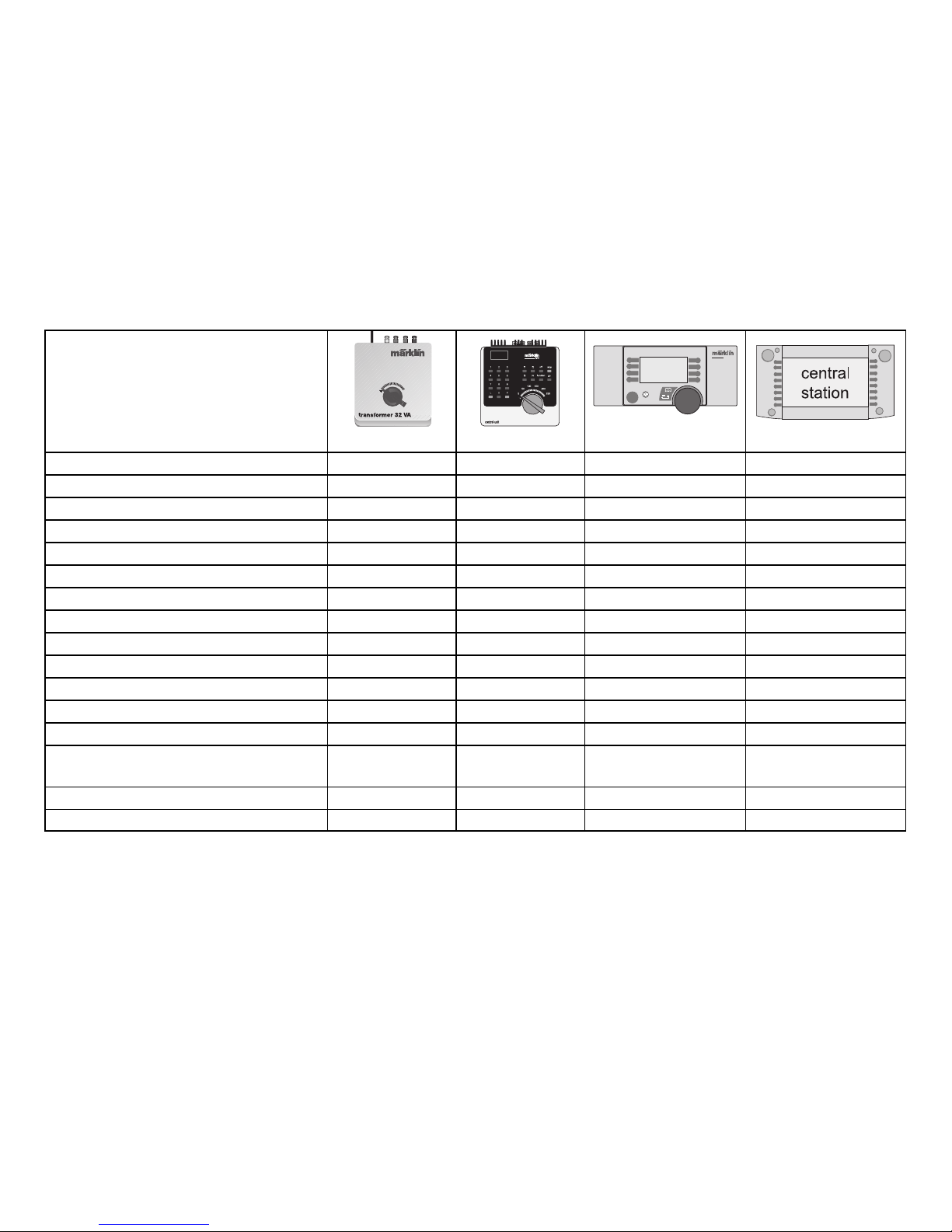
33
Styrbare funktioner
6647 6021 60652 60212
Frontbelysning
1)
Konstant tændt 2)40 / function+ off Belysningskontakt Belysningskontakt
Nummerskilt-belysning
1)
Konstant tændt 2)40 / f1
3)
Tast ved symbol Tast ved symbol
Lyd af dampdrivværk – 40 / f2
3)
Tast ved symbol Tast ved symbol
Lyden af en lokomotivfløjte – 40 / f3
3)
Tast ved symbol Tast ved symbol
Rangergear (kun ABV) – 40 / f4
3)
Tast ved symbol Tast ved symbol
Førerpladsbelysning
1)
– 41 / f1
3)
Tast ved symbol Tast ved symbol
Lyden af en lokomotivklokke – 41 / f2
3)
Tast ved symbol Tast ved symbol
Lyd: Fløjtesekvens før jernbaneoverskæring – 41 / f3
3)
Tast ved symbol Tast ved symbol
Slå lyden af pibende bremser fra – 41 / f4
3)
Tast ved symbol Tast ved symbol
Lyd: Luftpumpe – – – Tast ved symbol
Lyd: Injektor til/fra – – – Tast ved symbol
Lyd: Hjælpeblæser til/fra – – – Tast ved symbol
Lyd: Kobling fra/til – – – Tast ved symbol
Lyd: Skinnestød
– – – Tast ved symbol
(frekvens uafhængig af hastighed)
Lyd: Fjernelse af mudder med trykluft – – – Tast ved symbol
Lyd: Kabineradio – – – Tast ved symbol
STOP
STOP
mobile station
systems
1) => Ved drift med Control Unit, Mobile Station eller Central Station indkobles samtidig lyden af en dampdrevet dynamo.
2) => Belysningens intensitet er afhængig af, hvor høj forsyningsspændingen er på skinnerne.
3) => 40 = 1. adresse, 41 = 2. adresse.
Page 34
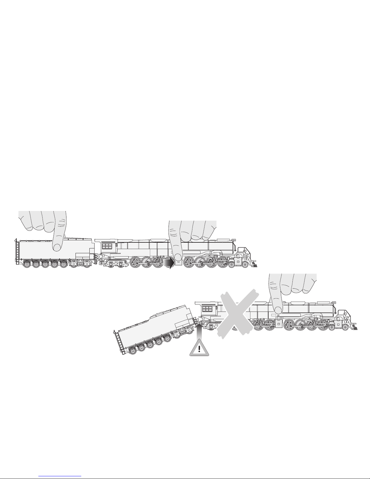
Pas på! Følgende vejledning skal
De absolut læse, inden De sætter
lokomotivet i drift på Deres modelbaneanlæg!
Af sikkerhedshensyn er denne tunge model med
mange detaljer skruet fast på den medleverede
sokkel. Vær meget varsom med at fjerne de 3 skruer
og husk at gemme dem. De bedes kun transportere
lokomotivet sikret på denne sokkel og i den tilhørende
originalkassette.
Tag kun fat om modellen på de viste steder for ikke
at beskadige nogle detaljer. Forbindelsen mellem
lokomotiv og tender må hverken strækkes eller foldes.
34
Page 35

Det kæmpestore lokomotiv stiller særlige
krav til Deres modelbaneanlæg. Tjek følgende
punkter inden første kørsel for at undgå skader
på lokomotiv eller anlæg:
● Mindesteradius udgør 360 mm. Vi anbefaler dog
om muligt at vælge større sporradier (> 500 mm).
● Lokomotivets fritrumsprofil er bredere og højere
end de mål, der er standard ved europæiske
modelbaner. Køreledningsmaster og signaler
skal derfor monteres så langt væk fra skinnernes
midtpunkt som muligt. De bedes også være
opmærksom på, at signaldrev, indstillingsgreb
eller lanterner ved sporskiftedrev kan blive berørt,
alt efter hvor de er installeret. Pas også på ved
tunnelportaler, brogelændre og perroner på afsnit
med sporkurver!
● Ved sporskifter skal der holdes en passende
hastighed. Dette gælder frem for alt ved sporskifter
med lille radius (indtil 437,5 mm) og kurvesporskifter.
● Lokomotivets konstruktion gør, at det først og
fremmest er beregnet til drift på Märklin C- og
K-spor. Ved meget langsom kørsel på bestemte
M-spor (kurvesporskifter, trevejssporskifte) kan
der forekomme kontaktforstyrrelser.
● Overgange til stigning eller fald samt overgangs-
spor (K-spor til C-spor eller M-spor) skal ikke
placeres lige der, hvor kurven begynder. Om fornødent bør overgangen flyttes en sporlængde.
Vi anbefaler en forsigtig prøvekørsel med en anden
person som hjælper.
De vedligeholdsarbejder, der forekommer ved
normal drift, beskrives i det følgende. Ved arbejde
på undersiden af lokomotivet bruges indsatsen
i kassetten som underlag. Den højtydende motor
og drivakslerne kræver ikke vedligehold. Angående
reparationer eller reservedele bedes De henvende
Dem til Deres Märklin-forhandler.
35
Page 36
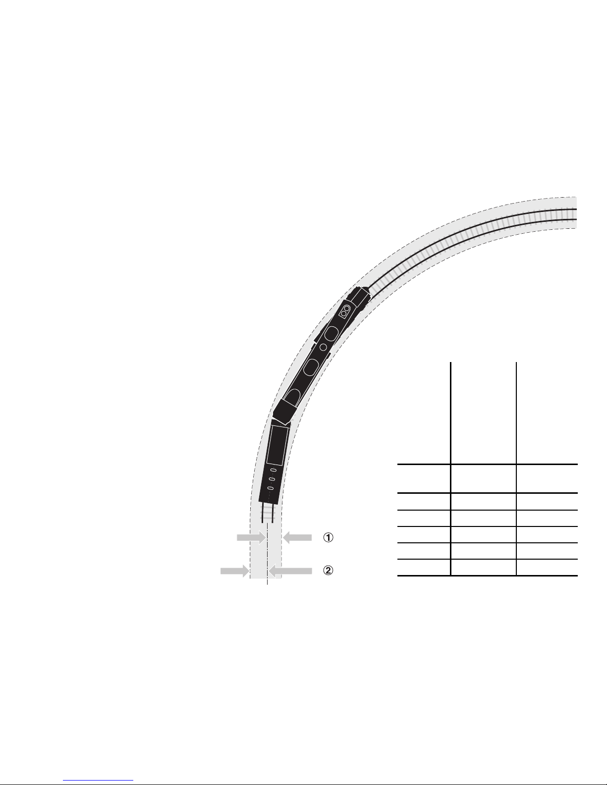
36
Radius inside outside
Radius innen außen
Rayon intérieur extérieur
radius binnen buiten
Radio interior exterior
Raggio interno esterno
Radie invändigt utvändigt
Radius indvendig udvendig
R = [mm] x = [mm] y = [mm]
360 27 36
437,5 26 34
515 25 31
579,3 24 29
643,6 23 28
Required clearance on bends
Erforderlicher Freiraum im Bogen
Espace libre nécessaire dans la courbe
Vereiste vrije ruimte in de boog
Espacio libre necesario en la curva
Spazio libero necessario in curva
Erforderligt fritt utrymme i kurvan
Nødvendig afstand til forhindringer kurven
x
y
Page 37
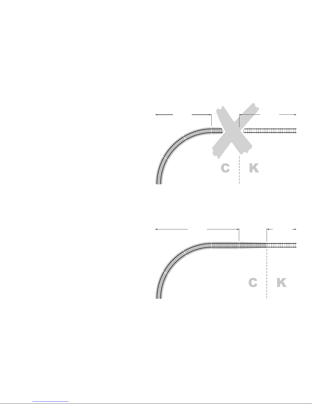
Transfer rail / gradient and start of bend
Übergangsgleis / Steigung und Bogenanfang
Rail de transition / montée et début de courbe
Overgangsrail / Steiging en boogbegin
Vía de transición / cuesta e inicio de la curva
Binario di raccordo / pendenza ed inizio della curva
Övergångsräls / stigning och början av kurva
Overgangsspor / stigning og kurvestart
37
(2200)24922(24…)
(2200)24922(24…)
Page 38
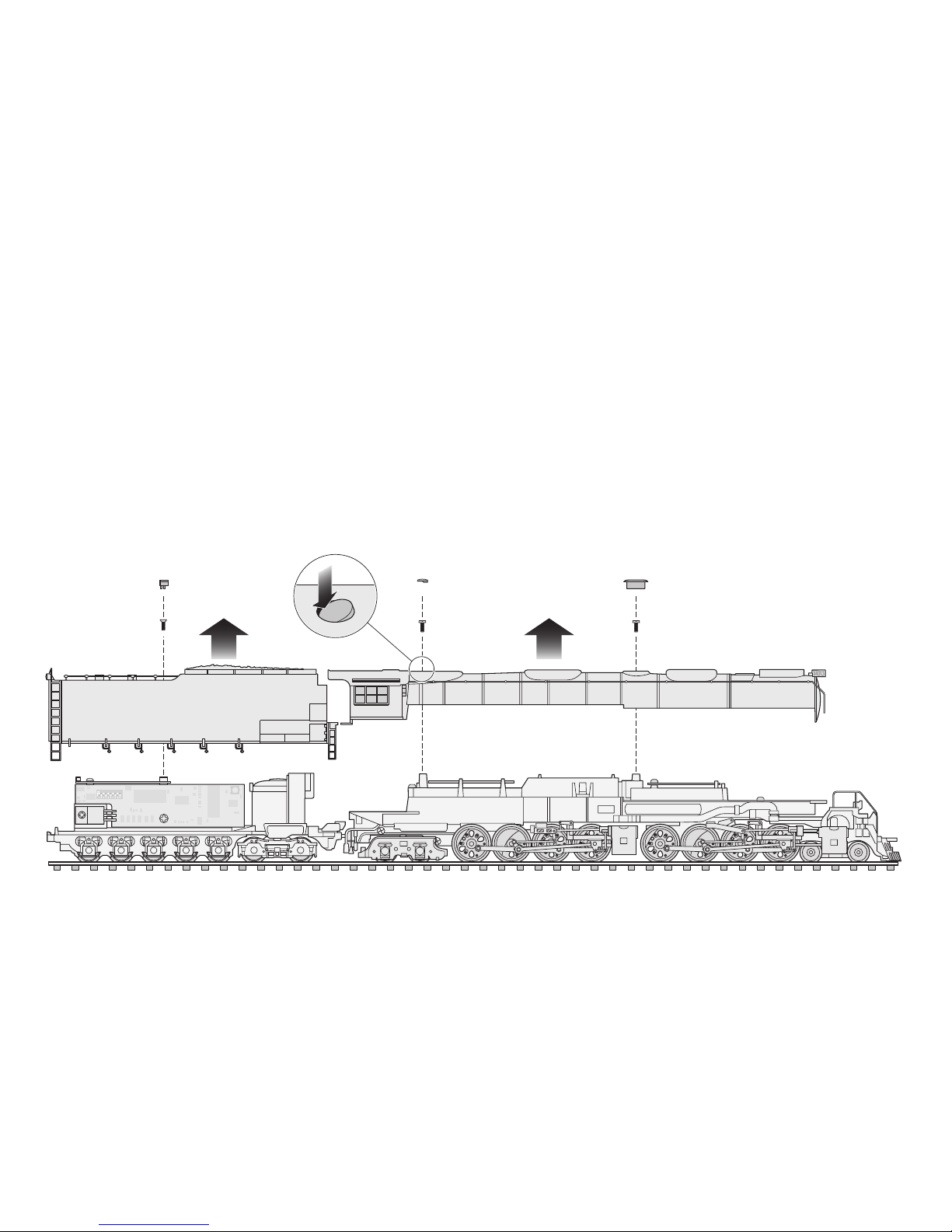
38
Removing the body
Gehäuse abnehmen
Enlever le boîtier
Kap afnemen
Retirar la carcasa
Smontare il mantello
Kåpan tas av
Overdel tages af
Page 39
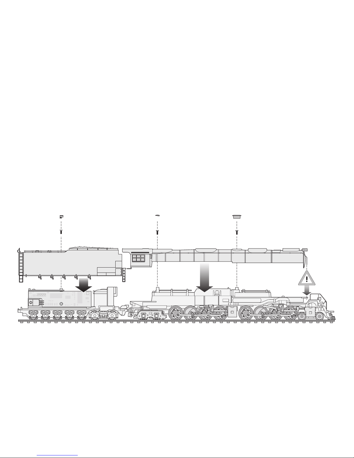
39
Fit housing
Gehäuse aufsetzen
Mettre le boîtier en place
Huis plaatsen
Colocar la carcasa
Applicare la scatola
Montera lokkåpan
Sæt huset på
Page 40

Setting Locomotive Parameters
with the Control Unit
1. Requirement: Setup as in diagram on page 44.
Only the locomotive to be changed can be on
the track.
2. Press the “Stop” and “Go” at the same time
until “99” blinks in the display.
3. Press the “Stop” button.
4. Enter the current locomotive address.
5. Hold the speed control knob in the reverse
direction position constantly. Press the
“Go” button while you do this.
6. The headlight on the locomotive will blink.
If no, repeat starting at Step 2.
7. Enter the register number for the parameter
to be changed (=> List on page 46).
8. Activate the direction reversal.
9. Enter new value (=> List on page 46).
10. Activate the direction reversal.
11. End the procedure by pressing the “Stop” button.
Now press the “Go” button.
Important: On the 1st address is changed, when
changing the locomotive’s address. The 2nd address
is always the following address.
=> Maximum value for the 1st address is 79.
Lokparameter einstellen
mit der Control Unit
1. Voraussetzung: Aufbau wie Grafik S. 44.
Nur die zu verändernde Lok ist auf dem Gleis.
2. „Stop“- und „Go“-Taste gleichzeitig drücken,
bis „99“ in der Anzeige aufblinkt.
3. „Stop“-Taste drücken.
4. Aktuelle Lokadresse eingeben.
5. Umschaltbefehl am Fahrregler dauernd schalten.
Dabei die „Go“-Taste drücken.
6. Licht bei der Lok blinkt. Wenn nicht ab Schritt 2
wiederholen.
7. Registernummer für den zu ändernden Parameter
eingeben (=> Liste auf Seite 46).
8. Fahrtrichtungswechsel betätigen.
9. Neuen Wert eingeben (=> Liste auf Seite 46).
10. Fahrtrichtungswechsel betätigen.
11. Vorgang beenden mit Drücken der „Stop“-Taste.
Anschließend Drücken der „Go“-Taste.
Hinweis: Verändert wird immer nur die 1. Adresse.
Die 2. Adresse ist immer die Folgeadresse.
=> Maximale 1. Adresse 79.
40
Page 41

Réglage des paramètres de la loco
avec la Control Unit
1. Condition: Montage comme sur illustration en
page 44. Seule la loco à modifier peut se trouver
sur la voie.
2. Pressez simultanément les touches „Stop“ et
„Go“ jusqu’à ce que le nombre „99“ clignote
sur l’écran.
3. Pressez la touche „Stop“.
4. Introduisez l’adresse de loco actuelle.
5. Tout en procédant à l’inversion sur le régulateur,
pressez la touche „Go“.
6. Les feux clignotent sur la loco. Si ce n’est pas
le cas, répétez l’étape 2.
7. Introduisez le numéro de registre pour le paramètre à modifier (=> liste en page 46).
8. Exécutez l’inversion du sens de marche.
9. Introduisez la nouvelle valeur (=> liste en page 46).
10. Exécutez l’inversion du sens de marche.
11. Terminez le processus en pressant la touche
„Stop“. Ensuite, pressez la touche „Go“.
Remarque: C’est toujours la 1
e
adresse qui est modi-
fiée. La 2
e
adresse est toujours l’adresse suivante.
=> 1eadresse maximale: 79.
Locparameters instellen
met de Control Unit
1. Voorwaarde: opbouw zoals tekening op
pagina 44. Alleen de loc die gewijzigd moet
worden op de rails.
2. ”Stop”- en ”Go”-toets gelijktijdig indrukken
tot ”99” in het display oplicht.
3. ”Stop”-toets indrukken.
4. Het actuele adres invoeren.
5. Omschakelcommando met de rijregelaar continu
bedienen. Daarbij de ”Go”-toets indrukken.
6. De verlichting van de loc knippert. Als dit niet
het geval is, vanaf stap 2 herhalen.
7. Het registernummer van de te wijzigen parameter
invoeren (=> lijst op pag. 46).
8. Rijrichtingomschakeling bedienen.
9. Nieuwe waarde invoeren (=> lijst op pag. 46).
10. Rijrichtingomschakeling bedienen.
11. Programmering beëindigen door het indrukken
van de ”Stop”-toets. Aansluitend de ”Go”-toets
indrukken.
Opmerking: het eerste adres kan altijd worden
gewijzigd. Het tweede adres is altijd het daarop volgende adres. Het eerst adres is maximaal adres 79.
41
Page 42

Parámetros de la locomotora configurables
con el Control Unit
1. Condición previa: montaje como el gráfico
pág. 44. En la vía debe encontrarse solamente
la locomotora a configurar.
2. Apretar simultáneamente la tecla “Stop” y “Go”
hasta que aparece “99” en pantalla.
3. Apretar la tecla “Stop”.
4. Marcar el código actualizado de la locomotora.
5. Mantener la orden de cambio de marcha
constantemente. Simultáneamente apretar
la tecla “Go”.
6. La luz de la locomotora parpadea. En caso contrario volver con la operación desde el punto 2.
7. Marcar el número de registro del parámetro
a modificar (véase lista en pág. 47).
8. Actuar otra vez el cambio de sentido de marcha.
9. Marcar el valor nuevo (=>lista en pág. 47).
10. Actuar el cambio de sentido de marcha.
11. Terminar la operación apretando la tecla “Stop”.
A continuación apretar la tecla “Go”.
Nota: Se modificará siempre sólo la 1ª dirección. La
2ª dirección es siempre la que viene a continuación.
=> El máximo de la 1ª dirección es 79.
Impostazione dei parametri della locomotiva
con la Control Unit
1. Predisposizione: assetto come da schema
a pag. 44. Soltanto la locomotiva da modificare
si trova sul binario.
2. Premere contemporaneamente i tasti „Stop“
e „Go“, fino a che sul visore lampeggia „99“.
3. Premere il tasto „Stop“.
4. Introdurre l’indirizzo attuale della locomotiva.
5. Azionare in modo continuo il comando di commutazione sul regolatore di marcia. A questo
punto premere il tasto „Go“.
6. L’illuminazione sulla locomotiva lampeggia.
In caso negativo, si ripeta a partire dal punto 2.
7. Introdurre il numero di registro per il parametro
da modificare (=> elenco a pagina 47).
8. Azionare la commutazione della direzione di marcia.
9. Introdurre il nuovo valore (=> elenco a pagina 47).
10. Azionare la commutazione della direzione di marcia.
11. Terminare il procedimento con la pressione
del tasto „Stop“. Successivamente premere
il tasto „Go“.
Avvertenza: viene modificato sempre soltanto
il 1° indirizzo. Il 2° indirizzo è sempre l’indirizzo
successivo. => Massimo 1° indirizzo 79.
42
Page 43

Lokparametrar ställs in
med Control Unit
1. Förutsättning: Montering som visas enligt
grafik på s. 44. Endast det lok som ska ändras
ska finnas på spåret.
2. Både „Stop“- och „Go“-tangenten hålls nedtryckt
tills „99“ blinkar på displayen.
3. „Stop“-tangenten hålls ner.
4. Aktuell lokadress matas in.
5. Omkopplingsordern på körreglaget ställs permanent. „Go“-tangenten trycks ner samtidigt.
6. Ljuset vid loket blinkar. Om det inte gör det,
upprepa instruktionerna från steg 2.
7. Registernumren för de parametrar som skall
ändras matas in (Se lista på s. 47).
8. Använd körriktningsväxling.
9. Mata in nytt värde (Se lista på s. 47).
10. Använd körriktningsväxling.
11. Proceduren avslutas genom att trycka ner „Stop“tangenten. Därefter hålls „Go“-tangenten ner.
OBS: Endast den första adressen ändras.
Den andra adressen är alltid följeadressen.
=> Maximal adress 1: 79.
Indstilling af lokomotivparametre
med Control Unit
1. Forudsætning: Opbygning som på grafikken
s. 44. Kun det lokomotiv, der skal ændres,
er på sporet.
2. Tryk samtidig på „Stop“- og „Go“-tasten,
indtil „99“ blinker i displayet.
3. Tryk på „Stop“-tasten.
4. Indtast den aktuelle lokomotivadresse.
5. Skift omskiftningskommandoen permanent på
køreregulatoren. Tryk derved på „Go“-tasten.
6. Lyset på lokomotivet blinker. Hvis ikke gentages
proceduren fra trin 2.
7. Indtast registernummeret for den parameter,
der skal ændres (=> liste på side 47).
8. Betjen køreretningsskiftet.
9. Indtast den nye værdi (=> liste på side 47).
10. Betjen køreretningsskiftet.
11. Afslut proceduren ved at trykke på „Stop“-tasten.
Tryk derefter på „Go“-tasten.
Henvisning: Det er altid kun 1. adresse, der ændres.
Adresse nr. 2 er altid følgeadressen.
=> Maskimale 1. adresse 79.
43
Page 44
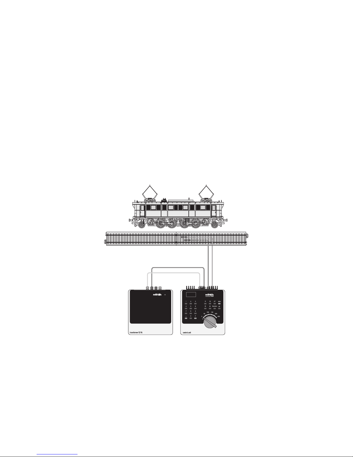
44
Changing Locomotive Parameters with the Control Unit.
Lokparameter mit Control Unit ändern.
Modification des paramètres avec la Control Unit.
Locparameter met de Control Unit.
Modificar los parámetros de la locomotora con el Control Unit.
Modifica dei parametri della locomotiva con la Control Unit.
Lokparametrar ändras med Control Unit.
Ændring af lokomotivparametre med Control Unit.
➀
Page 45
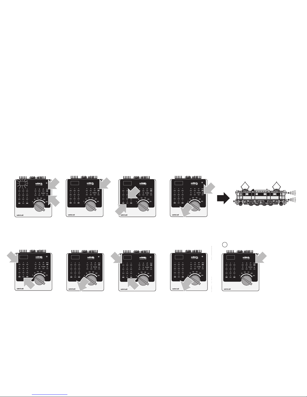
Changing Locomotive Parameters with the 6021 Control Unit.
Lokparameter verändern mit der Control Unit 6021.
Modification des paramètres de la locomotive avec la Control Unit 6021.
Locparameter wijzigen met de Control Unit.
Modificar los parámetros de la locomotora con el Control Unit 6021.
Modifica dei parametri della locomotiva con la Control Unit 6021.
Lokparametrar ändras med Control Unit 6021.
Ændring af lokomotivparametre med Control Unit 6021.
1
1
99
99
1
2
80
1
80
1
➁➂➃➄ ➅
2
1
01
01
1
1
2
10
➆➈➉➇
10
1
11
45
Page 46
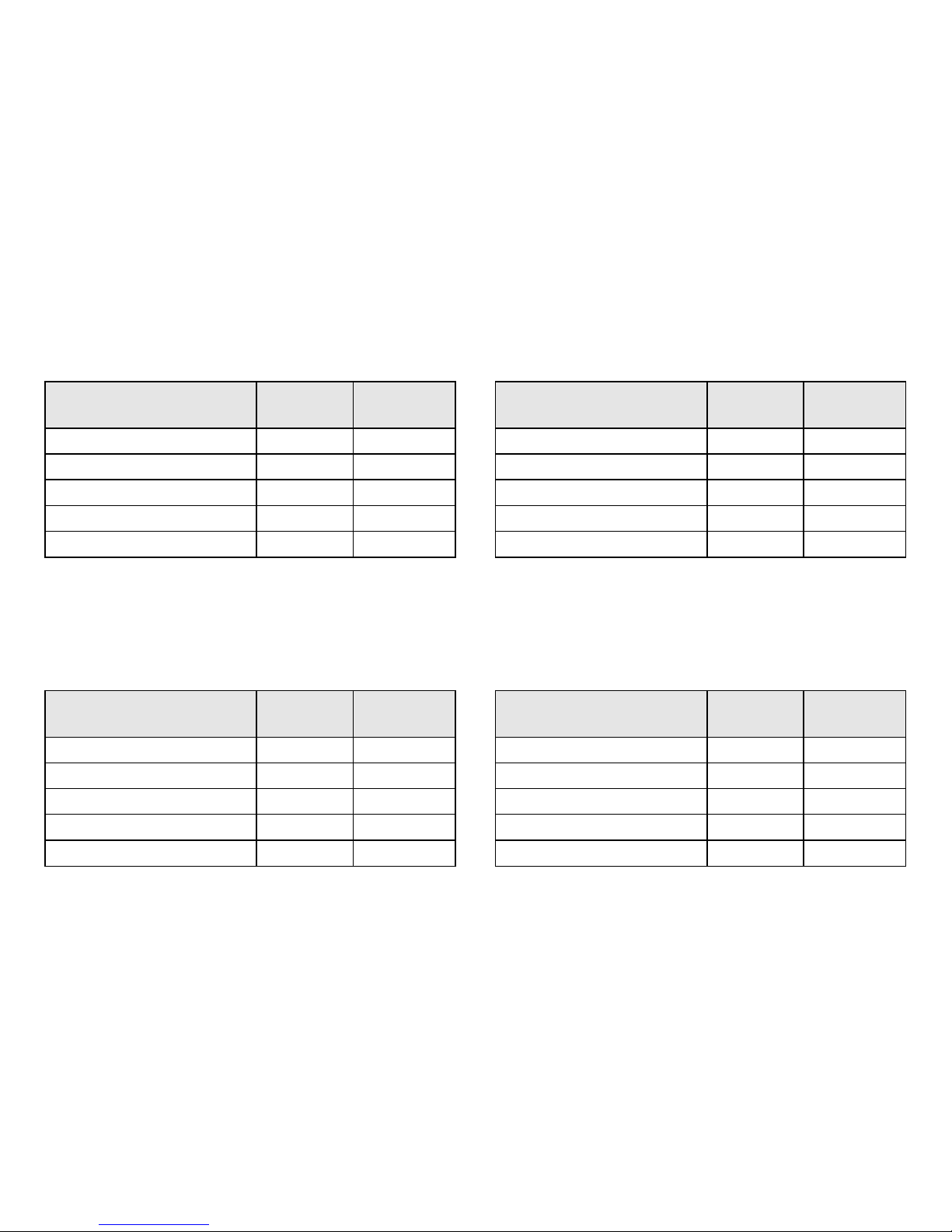
List of Parameters that Can Be Changed
with the Control Unit
Liste der veränderbaren Parameter
mit der Control Unit
Liste des paramètres modifiables
avec la Control Unit
Lijst met instelbare parameters
d.m.v. de Control Unit.
46
Parameter Register- Wert
nummer (min – max)
Adresse 01 01 – 80
Anfahrregelung 03 01 – 63
Bremsverzögerung 04 01 – 63
Höchstgeschwindigkeit 05 01 – 63
Lautstärke 63 01 – 63
Parameter Register- Waarde
nummer (min – max)
Adres 01 01 – 80
Optrekvertraging 03 01 – 63
Afremvertraging 04 01 – 63
Maximumsnelheid 05 01 – 63
Volume 63 01 – 63
Paramètre Numéro Valeur
du registre (min. – max.)
Adresse 01 01 – 80
Temporisation de démarrage 03 01 – 63
Temporisation de freinage 04 01 – 63
Vitesse maximale 05 01 – 63
Volume haut-parleur 63 01 – 63
Parameter Register Value
Number (min. – max.)
Address 01 01 – 80
Acceleration Control 03 01 – 63
Braking Delay 04 01 – 63
Maximum Speed 05 01 – 63
Volume 63 01 – 63
Page 47
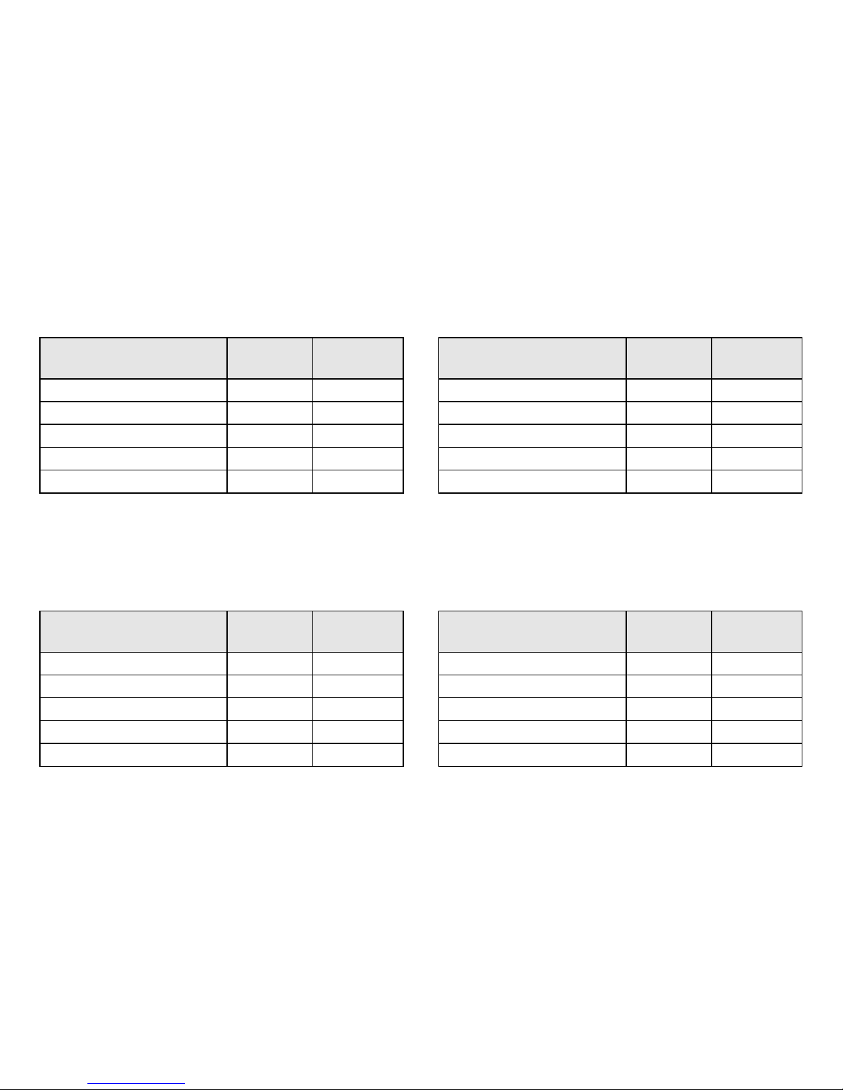
Lista de los parámetros que se pueden modificar
con el Control Unit
Elenco dei parametri modificabili
con la Control Unit
Lista på de parametrar som kan ändras
med Control Unit
Liste over de parametre, der kan indstilles
med Control Unit
47
Parámetro Número Valor
del registro (mín – máx)
Código 01 01 – 80
Regulación arranque 03 01 – 63
Frenado lento 04 01 – 63
Velocidad máxima 05 01 – 63
Volumen del sonido 63 01 – 63
Parametro Numero Valore
del registro (min – max)
Indirizzo 01 01 – 80
Regolazione di avviamento 03 01 – 63
Ritardo di frenatura 04 01 – 63
Velocità massima 05 01 – 63
Intensità sonora 63 01 – 63
Parameter Register- Värde
nummer (min – max)
Adress 01 01 – 80
Igångsättningsreglering 03 01 – 63
Bromsfördröjning 04 01 – 63
Toppfart 05 01 – 63
Ljudstyrka 63 01 – 63
Parameter Register- Værdi
nummer (min – maks)
Adresse 01 01 – 80
Opstartregulering 03 01 – 63
Bremseforsinkelse 04 01 – 63
Maksimalhastighed 05 01 – 63
Lydstyrke 63 01 – 63
Page 48

Changing Locomotive Parameters with the
Mobile Station / Central Station
Important: It is not necessary to change an address
when you are using the Mobile Station / Central Station.
Locomotives with the mfx technology register themselves independently with the controllers the moment
they are placed on the track and disappear from
the controller as soon as they are removed from the
layout. This process of registering with the controller
and disappearing from the controller usually takes
place within a couple of seconds. The other parameters (maximum speed, acceleration delay, braking
delay, volume of the sound effects) can be changed
with the appropriate submenu in Mobile Station /
Central Station.
Changing Locomotive Parameters
with the Mobile Station
1. Select the locomotive from the locomotive list.
2. Change to the submenu “EDIT LOC”.
3. Change to the submenu “VMAX”, “ACC”, “DEC”,
or “VOL”.
4. Enter the new value and accept it into the system.
Please note the information in the instructions for the
Mobile Station / Central Station.
Lokparameter mit der Mobile Station /
Central Station verändern
Hinweis: Bei der Mobile Station / Central Station ist
eine Änderung der Adresse nicht notwendig. Loks
mit mfx-Technologie melden sich selbstständig an
und wieder ab, sobald sie aufgegleist bzw. von der
Anlage genommen werden. Diese An- und Abmeldung
erfolgt normalerweise innerhalb ein paar Sekunden.
Die sonstigen Parameter (Höchstgeschwindigkeit,
Anfahrverzögerung, Bremsverzögerung, Lautstärke)
können über das entsprechende Untermenü in der
Mobile Station / Central Station verändert werden.
Lokparameter mit der Mobile Station
verändern
1. Lok aus der Lokliste auswählen.
2. Zum Untermenü „LOKÄNDERN“ wechseln.
3. Zum Untermenü „VMAX“, „ACC“, „DEC“ oder
„VOL“ wechseln.
4. Neuen Wert eingeben und übernehmen.
Beachten Sie die Hinweise in der Anleitung zur
Mobile Station / Central Station.
48
Page 49

Modification des paramètres de la locomotive
avec la Mobile-Station / Central Station
Remarque: Une modification de l’adresse n’est pas
possible avec la Mobile Station/ Central Station.
Les locomotives avec technologie mfx signalent de
façon autonome leur arrivée et leur départ dès qu’elles
sont posées sur ou retirées de la voie. Ces annonces
se font normalement endéans les quelques secondes.
Les autres paramètres (vitesse maximale, temporisation d’accélération, temporisation de freinage,
volume sonore) peuvent être modifiés via les sousmenus correspondants dans la Mobile Station /
Central Station.
Modification des paramètres de la loco
avec la Mobile Station
1. Sélectionnez la loco dans la liste.
2. Allez au sous-menu „MODIF LOC“.
3. Allez au sous-menu „VMAX“, „ACC“, „DEC“
ou „VOL“.
4. Entrez la nouvelle valeur et acceptez.
Respectez les remarques mentionnées dans
l’instruction accompagnant la Mobile Station /
Central Station.
Locparameters met het Mobile Station /
Central Station wijzigen
Opmerking: bij het Mobile Station / Central Station
is het niet nodig het adres te wijzigen. Locs met
mfx-technologie melden zichzelf aan en weer af
zodra ze op de rails worden gezet, dan wel van de
rails worden. Dit aan en afmelden gebeurt normaal
gesproken binnen een paar seconden. De andere
parameters (maximumsnelheid, optrekvertraging,
afremvertraging, volume) kunnen via het desbetreffende nevenmenu van het Mobile Station /
Central Station gewijzigd worden.
Locparameter wijzigen
met het Mobile Station
1. Loc uit de loclijst kiezen.
2. Ga naar het nevenmenu ”WYZIG LOC”.
3. Ga naar het nevenmenu ”MAX.SNELH.”,
”OPTREKKEN”, ”AFREMMEN” of ”VOL”.
4. Nieuwe waarde invoeren en overnemen.
Lees ook de opmerkingen in de gebruiksaanwijzing
van het Mobile Station / Central Station.
49
Page 50

Modificar los parámetros de la locomotora
con la Mobile Station / Central Station
Nota: Con la Mobile Station / Central Station no será
necesario modificar la dirección. Las locomotoras
con tecnología mfx se registran y se dan de baja,
tan pronto se hayan encarrilado en las vías o se
hayan retirado de la instalación. Este proceso para
registrarse y darse de baja requiere normalmente
un par de segundos. Los demás parámetros (velocidad máx., retardo de arranque, retardo de frenado,
volumen) se pueden modificar a través del correspondiente submenú de la Mobile Station /
Central Station.
Modificar los parámetros de la locomotora
con la Mobile Station
1. Seleccionar la locomotora de la lista de locomotora.
2. Pasar al menú subsidiario “EDIT LOC”.
3. Pasar al menú subsidiario “VMAX”, “ACC”, “DEC”
o “VOL”.
4. Introducir el nuevo código y memorizar.
Observe las indicaciones en las instrucciones
de la Mobile Station / Central Station.
Modifica dei parametri della locomotiva
con la Mobile Station / Central Station
Avvertenza: Nel caso della Mobile Station / Central
Station non è necessaria una modifica dell’indirizzo.
Le locomotive con tecnologia mfx si annunciano automaticamente, e tornano a disattivarsi, non appena
esse vengano fatte sviare dal binario o rispettivamente
tolte dall’impianto. Questo annuncio e disattivazione
normalmente si verifica entro un paio di secondi. Gli
altri parametri (velocità massima, ritardo di avviamento,
ritardo di frenatura, intensità sonora) possono venire
modificati tramite il corrispondente sottomenù nella
Mobile Station / Central Station.
Modifica dei parametri della locomotiva
con la Mobile Station
1. Selezionare la locomotiva dall’elenco locomotive.
2. Commutare al sottomenù „EDIT LOC“.
3. Commutare ai sottomenù „VMAX“, „ACC“, „DEC“
oppure „VOL“.
4. Introdurre il nuovo valore e accettarlo.
Prestate attenzione alle avvertenze nelle istruzioni
della Mobile Station / Central Station.
50
Page 51

Lokparameter ändras med Mobile-Station /
Central Station
OBS: Hos Mobile Station / Central Station behövs
ingen adressändring. Lok med mfx-teknologi rapporterar automatiskt när de sätts på spåret, respektive tas bort från anläggningen. Denna rapportering
(till/från) sker vanligtvis inom några sekunder. Andra
parametrar (toppfart, accelerationsfördröjning,
bromsfördröjning, ljudstyrka) kan ändras via mots
varande undermeny på Mobile Station/ Central
Lokparametrar ändras
med Mobile Station
1. Välj lok från loklistan.
2. Växla till undermenyn „EDIT LOC“.
3. Växla till undermenyn „VMAX“, „ACC“, „DEC“
eller „VOL“.
4. Mata in nytt värde och acceptera.
Glöm ej: Se även i anvisningarna i bruksanvisningen
för Mobile Station / Central Station!
Ændring af lokomotivparametre
med Mobile Station / Central Station
Henvisning: Ved Mobile Station / Central Station er
en ændring af adressen ikke nødvendig. Lokomotiver
med mfx-teknologi melder sig selvstændigt til og fra
igen, når de sættes på skinnerne eller tages af igen.
Denne til- og framelding sker normalt inden for et
par sekunder. De øvrige parametre (maksimalhastighed, opstartforsinkelse, bremseforsinkelse, lydstyrke)
kan ændres via den pågældende undermenu i
Mobile Station / Central Station.
Ændring af lokomotivparametre
med Mobile Station
1. Vælg lokomotivet fra listen.
2. Skift til undermenuen „EDIT LOC“.
3. Skift til undermenuen „VMAX“, „ACC“, „DEC“
eller „VOL“.
4. Indtast den nye værdi og overtag den.
Iagttag henvisningerne i vejledningen til
Mobile Station / Central Station.
51
Station.
Page 52
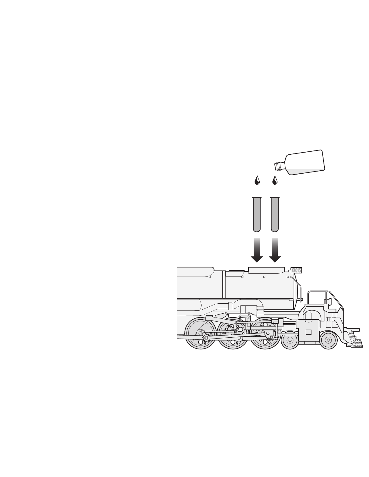
52
Can be equipped with a smoke unit
Rauchsatz nachrüstbar
Générateur de fumée remplaçable
Met rookgarnituur om te bouwen
El equipo de humo se puede colocar posteriormente
Inserto fumogeno sostituibile
Kan kompletteras med röksats
Røgaggregat kan eftermonteres
2 x Seuthe Nr. 11
02420
Remove the smoke generators before attempting
to change locomotive parameters!
Rauchsätze zum Ändern der Lokparameter
entfernen!
Enlever les fumigènes pour modifier les paramètres
de la locomotive!
Rookgeneratoren voor het wijzigen van de locparameters verwijderen.
Para modificar los parámetros de la locomotora
es necesario retirar los conjuntos de humo.
Rimuovere gli apparati fumogeni per la modifica
dei parametri della locomotiva!
Ta bort röksatser före ändring av lokparametrar!
Fjern røgsæt til ændring af lokomotivparameteren!
Page 53
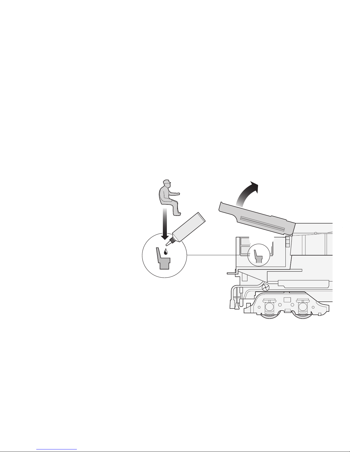
53
Install locomotive driver and stoker
Lokführer und Heizer einsetzen
Mettre le conducteur de la locomotive et le chauffeur en place
Loc-machinist en stoker plaatsen
Colocar el conductor de la locomotora y el fogonero
Collocare il macchinista ed il fuochista
Placera lokförare och eldare på plats
Indsæt lokomotivfører og fører
Do not use fast-acting glue!
Keinen Sekundenkleber verwenden!
Ne pas utiliser de colle à contact immédiat!
Geen secondenlijm gebruiken!
¡No utilizar pegamento rápido!
Non impiegare adesivo istantaneo!
Använd inte cyanoakrylatlim!
Brug ikke hurtigtørrende lim!
Page 54
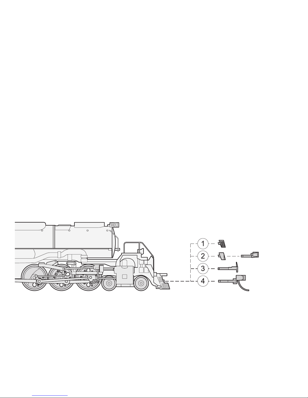
Front coupling connection:
● Cover closed
● Cover open with coupling mock-up
● Brake pipes
● Coupling hook (restricted use)
● Other systems (e.g. Kadee # 19)
Kupplungsaufnahme vorne:
● Abdeckung geschlossen
● Abdeckung offen mit Kupplungsattrappe
● Bremsleitungen
● Kupplungshaken (eingeschränkt verwendbar)
● Andere Systeme (z.B. Kadee # 19)
Logement de l'attelage à l'avant:
● Protection fermée
● Protection ouverte avec attrape d'attelage
● Conduites de frein
● Crochet d’attelage (utilisable avec restrictions)
● Autres systèmes (par ex. Kadee # 19)
Koppelingsopname vóór:
● Afdekking gesloten
● Afdekking open met koppelingsattrappe
● Remleidingen
● Koppelingshaak (beperkt bruikbaar)
● Andere systemen (b.v. Kadee # 19)
54
Page 55

Alojamiento del enganche, delante:
● Cubierta cerrada
● Cubierta abierta con modelo de enganche
● Tubos de frenado
● Gancho de tracción (de uso restringido)
● Otros sistemas (p.ej. Kadee nº 19)
Sede di attacco anteriore:
● Copertura chiusa
● Copertura aperta con imitazione di attacco
● Linee dei freni
● Gancio di attacco (limitatamente utilizzabile)
● Altri sistemi (ad esempio Kadee # 19)
Koppelfäste framtill:
● Sluten kåpa
● Öppen kåpa med koppelattrapp
● Bromsledningar
● Koppelhake (användbar med inskränkningar)
● Andra system (t.ex. Kadee # 19)
Koblingsholder fortil:
● Dække lukket
● Dække åbent med koblingsattrap
● Bremseledninger
● Koblingskroge (begrænsede anvendelses-
muligheder)
● Andre systemer (f.eks. Kadee # 19)
55
Rear coupling connection:
● Märklin short coupling
● Other systems (e.g. Kadee # 18)
Kupplungsaufnahme hinten:
● Märklin-Kurzkupplung
● Andere Systeme (z.B. Kadee # 18)
Logement d'attelage à l'arrière:
● Attelage court Märklin
● Autres systèmes (par ex. Kadee # 18)
Koppelingsopname achter:
● Märklin-kortkoppeling
● Andere systemen (b.v. Kadee # 18)
Alojamiento del enganche, detrás:
● Enganche apretado de Märklin
● Otros sistemas (p.ej. Kadee nº 18)
Sede di attacco posteriore:
● Attacco corto Märklin
● Altri sistemi (ad esempio Kadee # 18)
Koppelfäste baktill:
● Märklin kortkoppel
● Andra system (t.ex. Kadee # 18)
Koblingsholder bagtil:
● Märklin-kortkobling
● Andre systemer (f.eks. Kadee # 18)
Page 56
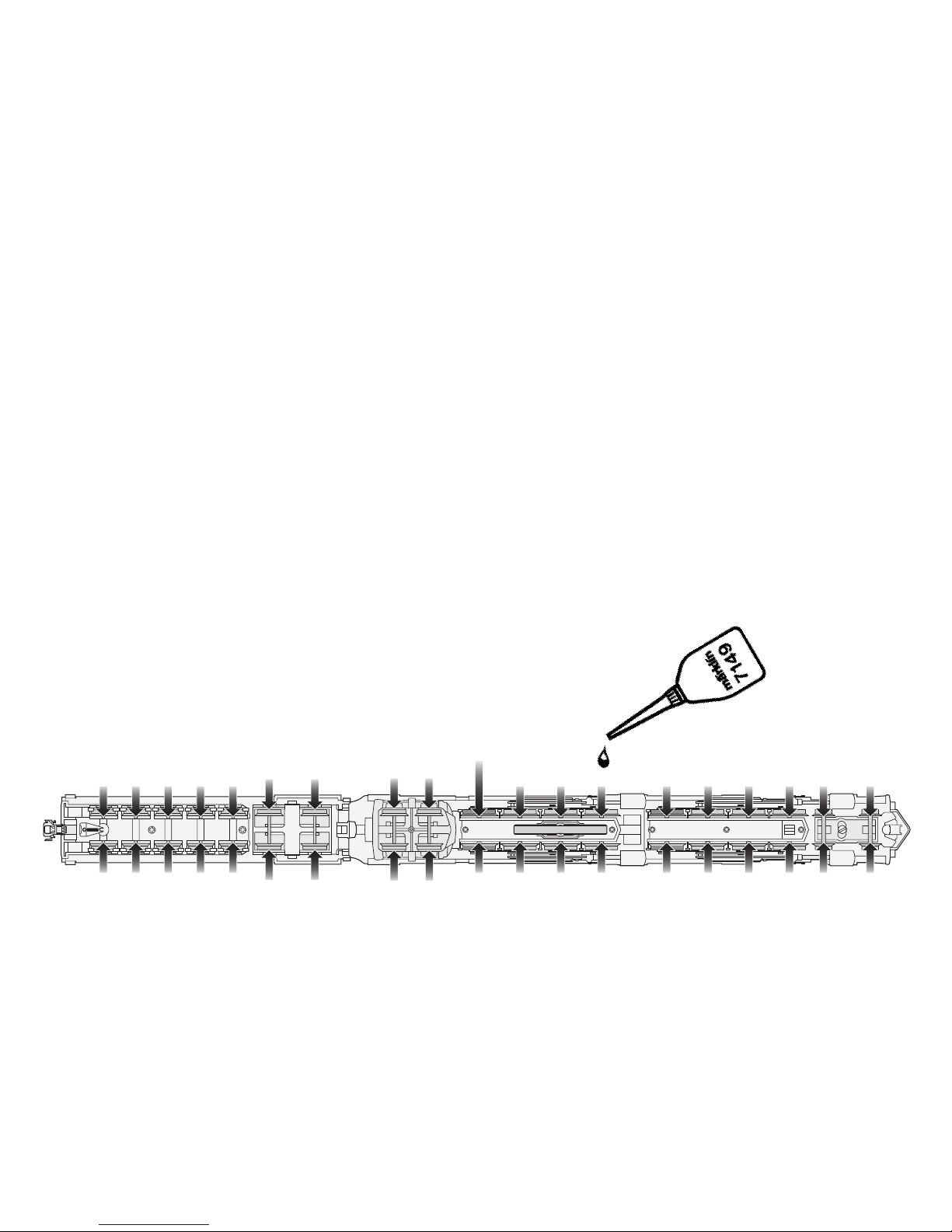
56
Lubrication after approximately 40 hours of operation
Schmierung nach etwa 40 Betriebsstunden
Graissage après environ 40 heures de marche
Smering na ca. 40 bedrijfsuren
Engrase a las 40 horas de funcionamiento
Lubrificazione dopo circa 40 ore di funzionamento
Smörjning efter ca. 40 driftstimmar
Smøring efter ca. 40 driftstimer
Do not oil the motor and universal coupling bearings!
Motor und Kardanlager nicht ölen !
Ne pas huiler le moteur et le palier du cardan !
Motor en cardanlager niet oliën!
¡No lubricar con aceite el motor ni los rodamientos del cardán!
Non oliare il motore ed il cuscinetto cardanico!
Var vänlig smörjs aldrig motor och kardanlager!
Smør ikke motor og kardanleje!
Page 57
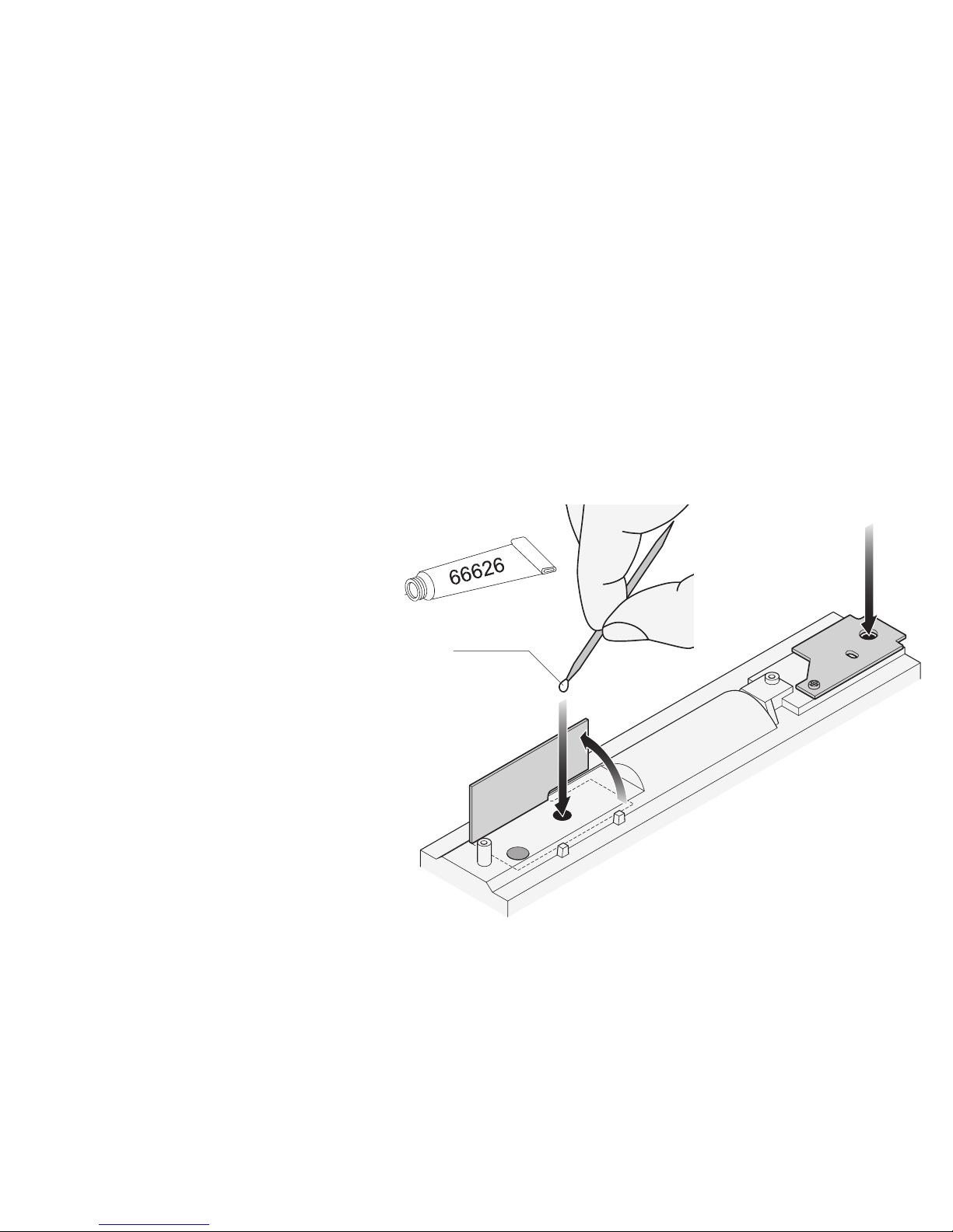
57
Grease first gear stage (after approx. 120 hours of operation / 4 years)
Erste Getriebestufe schmieren (nach ca. 120 Betriebsstunden / 4 Jahren)
Lubrifier le premier niveau d’engrenage (au bout de 120 heures de fonctionnement / 4 ans)
Eerste transmissietrap smeren (na ca. 120 bedrijfsuren / 4 jaar)
Lubricar el primer grado de engranaje (después de aprox. 120 horas de funcionamiento / 4 años)
Lubrificare il primo stadio del riduttore (dopo circa 120 ore di funzionamento / 4 anni)
Smörj första kuggväxelsteget (efter ca 120 driftstimmar / 4 år)
Smør første geartrin (efter ca. 120 driftstimer / 4 år)
Use only special grease!
No oil! No domestic grease!
Bitte nur Spezialfett verwenden!
Kein Öl! Kein Haushaltsfett!
N’utiliser que de la graisse spéciale!
Ne pas utiliser d’huile!
Ne pas utiliser de graisse ménagère!
Uitsluitend speciaal vet gebruiken!
Geen olie! Geen huishoudvet!
¡Utilizar sólo grasa especial!
¡No utilizar aceite!
¡No utilizar grasa de uso doméstico!
Impiegare solo grasso speciale!
Non usare olio! Non usare grasso da cucina!
Var vänlig använd endast specialfett!
Ingen olja! Inget hushållsfett!
Brug kun special-smøremiddel!
Ikke olie! Ikke gængse smøremidler!
Trix 66626
Page 58
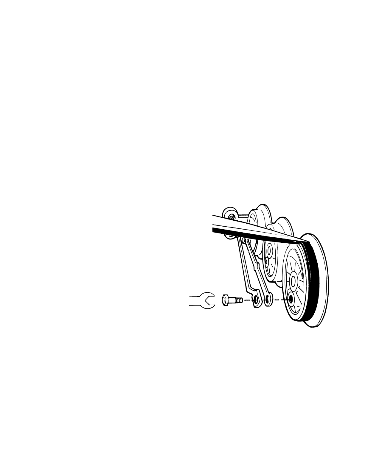
58
Changing traction tires
Haftreifen auswechseln
Changer les bandages d’adhérence
Antislipbanden vervangen
Cambio de los aros de adherencia
Sostituzione delle cerchiature di aderenza
Slirskydd byts
Friktionsringe udskiftes
7153
2,5 mm
0262
Page 59
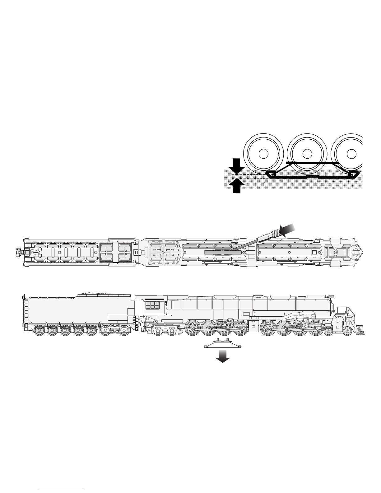
59
Changing the pickup shoe
Schleifer auswechseln
Changer le frotteur
Vervangen van het sleepcontact
Cambio del patín toma-corriente
Sostituzione del pattino
Byt släpsko
Udskiftning af slæbesko
ca. 2 mm
206 370
Page 60

This device complies with Part 15 of the FCC Rules.
Operation is subject to the following two conditions:
(1) This device may not cause harmful interference, and
(2) this device must accept any interference received, including
interference that may cause undesired operation.
Gebr. Märklin & Cie. GmbH
Postfach 8 60
D-73008 Göppingen
www.maerklin.com
610 725 09 04 he na
Änderungen vorbehalten
Copyright by
Gebr. Märklin & Cie. GmbH
 Loading...