

Page 1
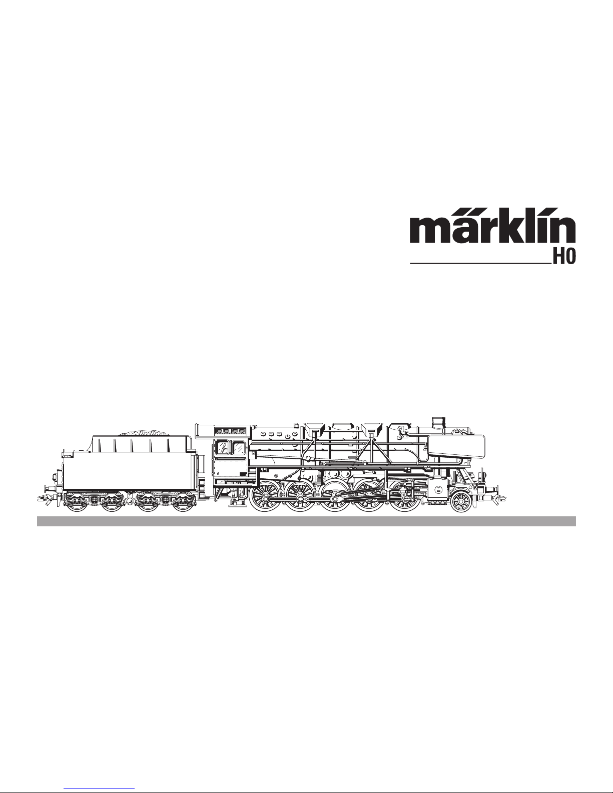
Modell der Serie 150 X
37887
BD Regensburg
Bw Weiden
44 333
Page 2

2
Information zum Vorbild
Schon im ersten Beschaffungsplan der neugegründe
ten Deutschen Reichsbahn (DRG) war eine schwere
Güterzuglokomotive mit fünf gekuppelten Achsen und
20 t Achslast vorgesehen. Die Ausrüstung mit zwei
oder drei Zylinder stand zur Diskussion. Daher wurden
im Jahr 1926 je zehn Maschinen mit zwei Zylinder als
Baureihe BR 43 und drei Zylinder als BR 44 gebaut.
Nach verschiedenen konstruktiven Änderungen wurden
erst von 1937 bis 1944 insgesamt 1753 Einheiten der
BR 44 für die DRG gebaut.
Bei beiden deutschen Bahnen bildeten die Loks der BR
44 in der Nachkriegszeit das Rückgrat der Güterzugförderung. Bei der Deutschen Reichsbahn (DR) wurden
die Maschinen zum Teil auf Ölhaupt- oder auf Koh
lenstaubfeuerung umgebaut. Auch bei der Deutschen
Bundesbahn (DB) erhielten 32 Loks eine Ölfeuerung.
Information about the Prototype
A heavy freight locomotive with five coupled axles and
a 20 ton axle load was part of the first procurement
plans of the newly founded German State Railroad
(DRG). There was a debate regarding whether it should
have two or three cylinders, and accordingly ten units
each with two cylinders as the class 43 and with three
cylinders as the class 44 were built in 1926. After vari
ous design changes total of 1,753 units of the class 44
were built from 1937 to 1944 for the DRG.
On the German railways the class 44 locomotives
formed the backbone of freight transport motive power
in the postwar period. On the German State Railroad
(DR) some of these units were converted to mostly oil
firing and to coal powder firing. Thirtytwo units on the
German Federal Railroad (DB) were also equipped for
oil firing.
Page 3

3
Informations concernant la locomotive réele
Le premier plan d’acquisition des Chemins de fer
nouvellement créés de la Deutsche Reichsbahn (DRG)
prévoyait déjà une locomotive lourde pour trains de
marchandises avec cinq essieux accouplés et une
charge axiale de 20 t. L’équipement avec deux ou
trois cylindres a été discuté, raison pour laquelle dix
machines à deux cylindres ont été construites en 1926
en guise de série BR 13, ainsi que dix machines à trois
cylindres en guise de série BR 44. Après plusieurs
modifications de la construction, 1753 unités de la BR
44 ont été construites pour les Chemins de fer de la
Deutsche Reichsbahn entre 1937 et 1944.
Dans les deux Chemins de fers allemands, les locomotives de la série BR 44 ont constitué la colonne vertébrale du transport de marchandises durant la période
de l’aprés-guerre. Les Chemins de fer de la Deutsche
Reichsbahn (DR) ont adapté une partie des machines
à un chauffage principal à l’huile ou à la poussière de
charbon. Les Chemins de fer de la Deutsche Bundesbahn ont eux aussi doté 32 locomotives d’un chauffage
à l’huile.
Informatie van het voorbeeld
Reeds in de eerste plannen voor de aanschaf van
nieuw materieel had de pas opgerichte Deutsche
Reichsbahn (DRG) een zware goederentreinlokomotief
met vijf gekoppelde assen en 20 ton aslast opgenomen. De uitvoering met twee of drie cilinders stond ter
discussie en daarom werden er in 1926 tien machines
met twee cilinders als serie BR 43 en tien machines
met drie cilinders als serie BR 44 gebouwd. Na diverse
constructieve veranderingen werden pas vanaf 1937 tot
1944 in totaal 1753 eenheden van de serie 44 voor de
DRG gebouwd.
Bij de Duitse spoorwegen vormden de loks van de serie
44 in de naoorlogse tijd de ruggegraat bij het goederen
transport. Bij de Deutsche Reichsbahn (DR) werden
de machines voor een deel omgebouwd naar olie als
belangrijkste brandstof of voor de verbranding van
koolstof. Ook bij de Deutsche Bundesbahn (DB) kregen
32 loks oliestook.
Page 4

4
Funktion
• Mögliche Betriebssysteme:
Märklin Transformer 6647, Märklin Delta,
Märklin Digital, Märklin Systems.
• Erkennung der Betriebsart: automatisch.
• Einstellbare Adressen: 01 – 80.
Adresse ab Werk:
44.
• Mfx-Technologie für Mobile Station /
Central Station.
• Name ab Werk:
S. 150 X 1518
• Veränderbare Anfahrverzögerung.
• Veränderbare Bremsverzögerung.
• Veränderbare Höchstgeschwindigkeit.
• Einstellen der Lokparameter elektronisch über Cont
rol Unit, Mobile Station oder
Central Station.
• Eingebaute Geräuschelektronik, nur im Betrieb mit
Control Unit oder Märklin Systems nutzbar.
• Zusätzliche schaltbare Geräusche.
• Rauchgenerator nachrüstbar.
Die bei normalem Betrieb anfallenden Wartungsarbei
ten sind nachfolgend beschrieben. Für Reparaturen
oder Ersatzteile wenden Sie sich bitte an Ihren MärklinFachhändler.
Sicherheitshinweise
• Die Lok darf nur mit einem dafür bestimmten Be
-
triebssystem eingesetzt werden.
Nur Transformatoren verwenden, die Ihrer örtli
chen Netzspannung entsprechen.
Keinesfalls Transformatoren für eine Netzspan
nung von 220 V bzw. 110 V einsetzen.
• Beachten Sie unbedingt die Sicherheitshinweise in
der Gebrauchsanleitung zu Ihrem Betriebssystem.
• Für den konventionellen Betrieb der Lok muss
das Anschlussgleis entstört werden. Dazu ist das
Entstörset 74046 zu verwenden. Für Digitalbetrieb ist
das Entstörset nicht geeignet.
Jegliche Garantie-, Gewährleistungs- und Schadensersatzansprüche sind ausgeschlossen, wenn in Märklin-Produkten nicht
von Märklin freigegebene Fremdteile eingebaut werden und /
oder Märklin-Produkte umgebaut werden und die eingebauten
Fremdteile bzw. der Umbau für sodann aufgetretene Mängel und
/ oder Schäden ursächlich war. Die Darlegungs- und Beweislast
dafür, dass der Einbau von Fremdteilen oder der Umbau in bzw.
von Märklin-Produkten für aufgetretene Mängel und / oder Schäden nicht ursächlich war, trägt die für den Ein- und / oder Umbau
verantwortliche Person und / oder Firma bzw. der Kunde.
!
Page 5
5
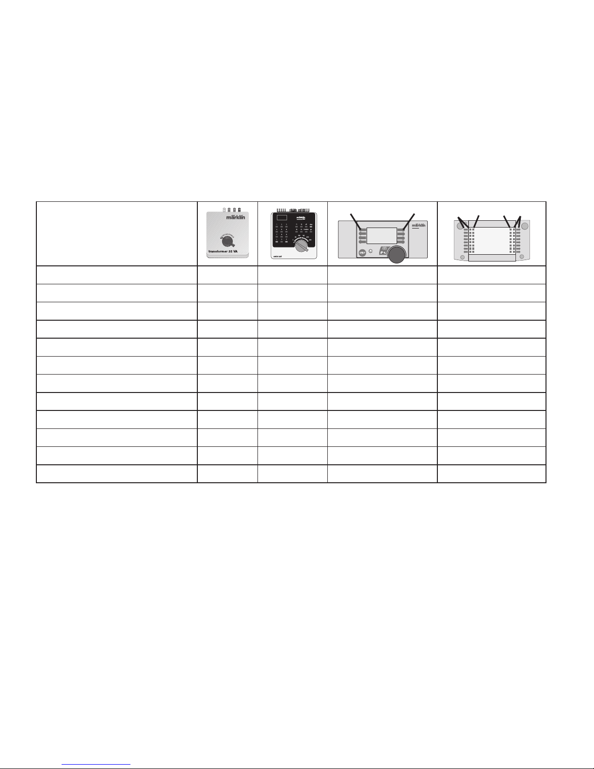
Schaltbare Funktionen
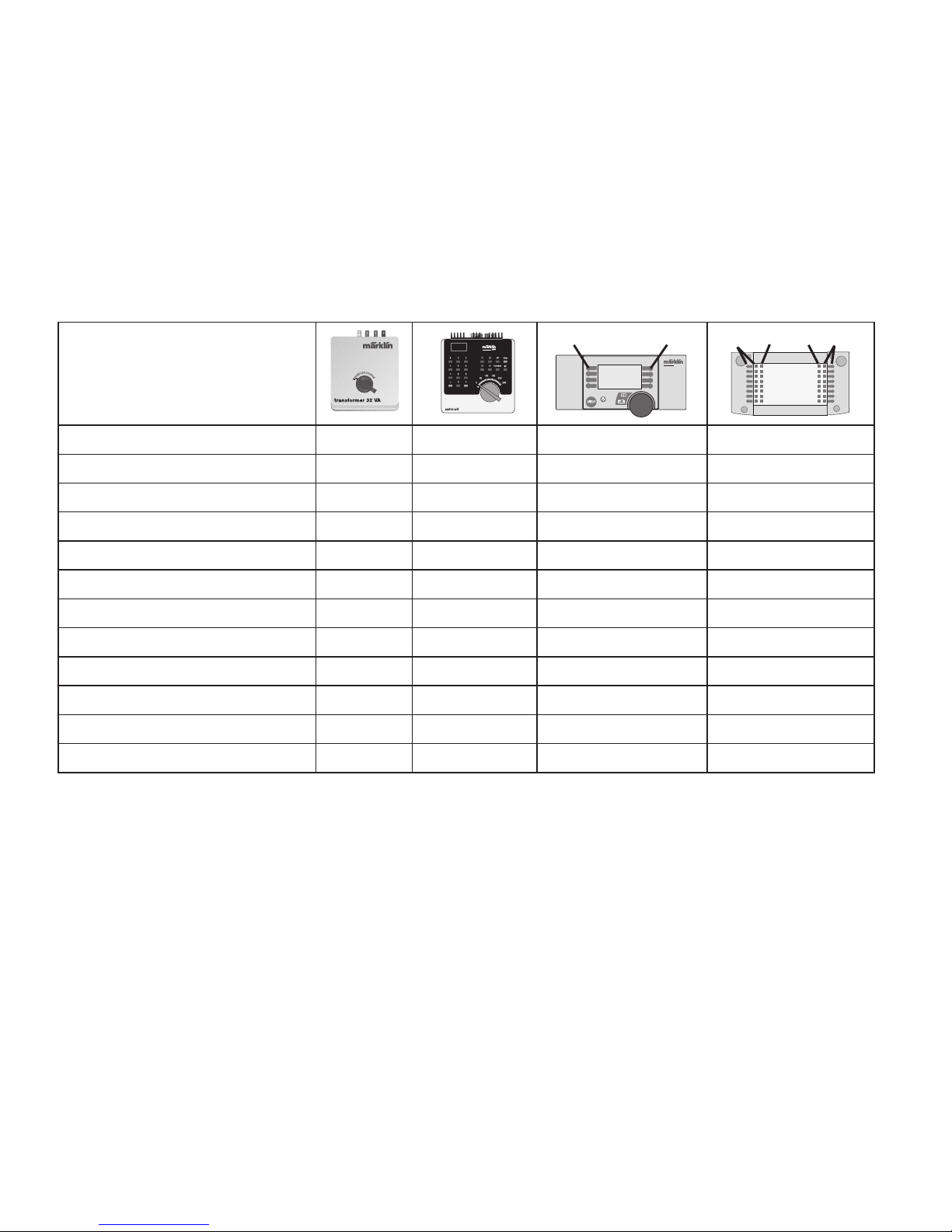
Spitzensignal an
1)
function + off Licht-Taste Taste f0
Rauchgenerator
2)
an f1 Taste 7 Taste f1
Telexkupplung
— f2 Taste 6 Taste f2
Geräusch: Dampftriebwerk — f3 Taste 3 Taste f3
ABV — f4 Taste 2 Taste f4
Geräusch: Pfeife lang — —
Taste 4
Taste f5
Geräusch: Luftpumpe — — Taste 8 Taste f6
Geräusch: Rangierpfeife — —
Taste 5
Taste f7
Bremsenquietschen aus
— — Taste 1 Taste f8
Geräusch: Dampf ablassen — —
—
Taste f9
Geräusch: Kohle schaufeln — — — Taste f10
Geräusch: Schüttelrost
— — — Taste f11
central
station
60212
f0
f0f8
f8
STOP
mobile station
systems
1
5
1) Intensität von der Höhe der Fahrspannung abhängig.
2) Gehört nicht zum Lieferumfang.
Page 6

6
Function
• Possible operating systems:
6646/6647 Märklin Transformer, Märklin Delta,
Märklin Digital, Märklin Systems.
•
Recognition of the mode of operation: automatic.
• Addresses that can be set: 01 – 80.
Address set at the factory:
44.
• Mfx technology for the Mobile Station /
Central Station.
• Name set at the factory:
S. 150 X 1518
• Adjustable acceleration.
• Adjustable Braking delay.
• Adjustable maximum speed.
• Setting the locomotive parameters electronically with
the Control Unit, Mobile Station or Central Station.
•
Built-in sound effects circuit, can only be used in operation
with the Control Unit or Märklin Systems.
• Additional sound effects that can be controlled.
• This locomotive can be retrofitted with a smoke
generator.
The maintenance work necessary with normal operation of this locomotive is described below. Please see
your authorized Märklin dealer for repairs or spare
parts.
Safety Warnings
• This locomotive is to be used only with an operating
system designed for it.
Use only transformers rated for your local hosehold power. Do not under any circumstances
use transformers rated for 220 volts or 110 volts
• Pay close attention to the safety warnings in the
instructions for your operating system.
• The feeder track must be equipped to prevent inter
ference with radio and television reception, when the
locomotive is to be run in conventional operation.
The 74046 interference suppression set is to be used
for this purpose.
No warranty or damage claims shall be accepted in those cases
where parts neither manufactured nor approved by Märklin have
been installed in Märklin products or where Märklin products
have been converted in such a way that the non-Märklin parts
or the conversion were causal to the defects and / or damage
arising. The burden of presenting evidence and the burden of
proof thereof, that the installation of non-Märklin parts or the
conversion in or of Märklin products was not causal to the
defects and / or damage arising, is borne by the person and / or
company responsible for the installation and / or conversion, or
by the customer.
!
Page 7
7
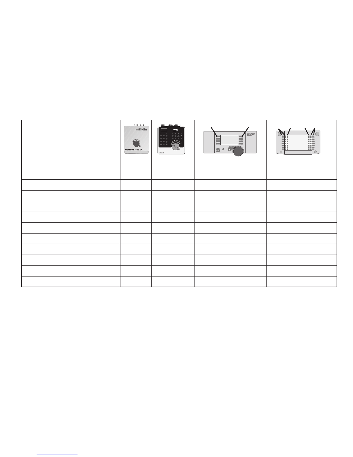
1) Intensity dependent on the level of supply voltage.
2) Not included in delivery scope.
Controllable Functions
Headlights on
1)
function + off Headlight button Button f0
Smoke Generator
2)
on f1 Button 7 Button f1
Telex Couplers
— f2 Button 6 Button f2
Locomotive operating sounds
— f3 Button 3 Button f3
ABV — f4 Button 2 Button f4
Sound effect: long whistle blast
— —
Button 4
Button f5
Sound effect: Air pump
— — Button 8 Button f6
Sound effect: range whistle
— —
Button 5
Button f7
Squealing brakes off
— — Button1 Button f8
Sound effect: blowing off steam
— —
—
Button f9
Sound effect: Coal being shoveled
— —
—
Button f10
Sound effect: rocker grate
— — — Button f11
central
station
60212
f0
f0f8
f8
STOP
mobile station
systems
1
5
Page 8

8
Fonction
• Systèmes d’exploitation possibles:
Märklin Transformer 6647, Märklin Delta,
Märklin Digital, Märklin Systems.
•
Détection du mode d’exploitation: automatique.
• Adresses disponibles: 01 – 80.
Adresse encodée en usine:
44.
• Technologie Mfx pour Mobile Station /
Central Station.
• Nom en codee en usine:
S. 150 X 1518
• Temporisation d’accélération réglable.
• Temporisation de freinage réglable.
• Vitesse maximale réglable.
• Réglage des paramètres de la loco électroniquement
à l’aide de la Control Unit, de la Mobile Station ou de
la Central Station.
• Bruiteur électronique intégré, utilisable uniquement
lors d’exploitation avec la Control Unit ou Märklin
Systems.
• Bruitages complémentaires commutables.
• Possibilité d’installer un générateur fumigène.
Les travaux d‘entretien occasionnels à effectuer en exploitation normale sont décrits plus loin. Pour toute réparation
ou remplacement de pièces, adressez-vous à votre
détaillant-spécialiste Märklin.
Remarques importantes sur la sécurité
• La locomotive ne peut être mise en service qu’avec
un système d’exploitation adéquat .
Utilisez uniquement des transformateurs corres
pondant à la tension secteur locale.
Bon courage en aucun cas des transformateurs pour
une tension secteur de 220 V, respectivement 110 V.
• Veuillez impérativement respecter les remarques sur
la sécurité décrites dans le mode d’emploi en ce qui
concerne le système d’exploitation.
• Pour l’exploitation de la locomotive en mode conventionnel, la voie de raccordement doit être dépa
-
rasitée. A cet effet, utiliser le set de déparasitage réf.
74046. Le set de déparasitage ne convient pas pour
l’exploitation en mode numérique
Tout recours à une garantie commerciale ou contractuelle ou à
une demande de dommages-intérêt est exclu si des pièces non
autorisées par Märklin sont intégrées dans les produits Märklin
et / ou si les produits Märklin sont transformés et que les pièces
d’autres fabricants montées ou la transformation constituent
la cause des défauts et / ou dommages apparus. C’est à la
personne et / ou la société responsable du montage / de la
transformation ou au client qu’incombe la charge de prouver
que le montage des pièces d’autres fabricants sur des produits
Märklin ou la transformation des produits Märklin n’est pas à
l’origine des défauts et ou dommages apparus.
!
Page 9
9
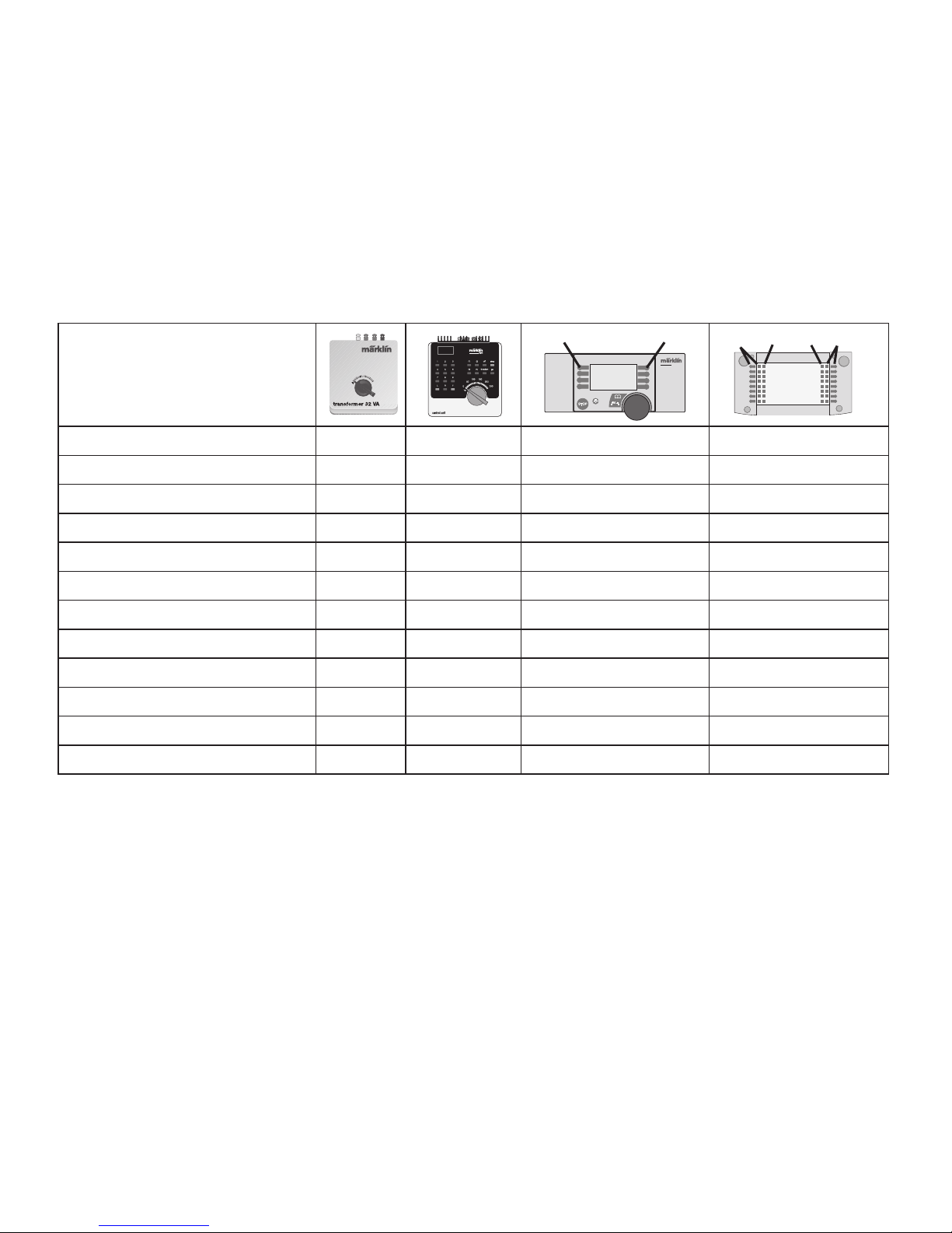
1) L’intensité est fonction de la tension d’alimentation.
2) Ne fait pas partie de la fourniture.
Fonctions commutables
Fanal marche
1)
function + off Touche éclairage
Touche f0
Générateur de fumée
2)
marche f1 Touche 7
Touche f1
Attelage Telex — f2 Touche 6
Touche f2
Bruit de roulement — f3 Touche 3
Touche f3
ABV — f4 Touche 2
Touche f4
Bruitage : sifflet long — —
Touche 4
Touche f5
Compresseur — — Touche 8
Touche f6
Bruitage sifflet de manoeuvre
— —
Touche 5
Touche f7
Grincement de freins désactivé
— — Touche 1
Touche f8
Bruitage échappement vapeur — — —
Touche f9
Bruitage pelleetes de charbon
— — —
Touche f10
Bruitage grille à secousses
— — —
Touche f11
central
station
60212
f0
f0f8
f8
STOP
mobile station
systems
1
5
Page 10

10
Werking
• Mogelijke bedrijfssystemen:
Märklin Transformer 6647, Märklin Delta,
Märklin Digital, Märklin Systems.
• Herkenning van het bedrijfssysteem: automatisch.
• Instelbare adressen: 01- 80.
Vanaf de fabriek:
44.
• Mfx-technologie voor het Mobile Station / Central
Station.
• Naam af de fabriek:
S. 150 X 1518
• Instelbare optrekvertraging.
• Instelbare afremvertraging.
• Instelbare maximumsnelheid.
• Elektronische instelling van de locomotiefparameters
via de Control Unit, Mobile Station of Central Station.
• Ingebouwde geluidselektronica, alleen bruikbaar in
het bedrijf met de Control Unit of Märklin Systems.
• Extra schakelbare geluiden.
• Mogelijkheid om rookgenerator in te bouwen.
De in het normale bedrijf voorkomende onderhoudswerkzaamheden zijn verderop beschreven. Voor repa
ratie of onderdelen kunt u zich tot uw Märklin winkelier
wenden.
Veiligheidsvoorschriften
• De loc mag alleen met een daarvoor bestemd be
-
drjfssysteem.
Alleen transformatoren gebruiken die geschikt zijn
voor de bij u geldende netspanning.
In geen geval transformatoren voor een netspan
-
ning van 220 V dan wel 110 V gebruiken.
• Voor het conventionele bedrijf met de loc dient de
aansluitrail te worden ontstoort. Hiervoor dient men
de ontstoor-set 74046 te gebruiken. Voor het digitale
bedrijf is deze ontstoor-set niet geschikt.
• Lees ook aandachtig de veiligheidsvoorschriften in
de gebruiksaanwijzing van uw bedrijfssysteem.
Elke aanspraak op garantie en schadevergoeding is uitgesloten,
wanneer in Märklin-producten niet door Märklin vrijgegeven
vreemde onderdelen ingebouwd en / of Märklin-producten omgebouwd worden en de ingebouwde vreemde onderdelen resp.
de ombouw oorzaak van nadien opgetreden defecten en / of
schade was. De aantoonplicht en de bewijslijst daaromtrent, dat
de inbouw van vreemde onderdelen in Märklin-producten of de
ombouw van Märklin-producten niet de oorzaak van opgetreden
defecten en / of schade is geweest, berust bij de voor de inbouw
en/of ombouw verantwoordelijke persoon en / of firma danwel
bij de klant.
!
Page 11
11
1) Intensiteit afhankelijk van de hoogte van de voedingsspanning.
2) Maakt geen deel uit van het leveringspakket.
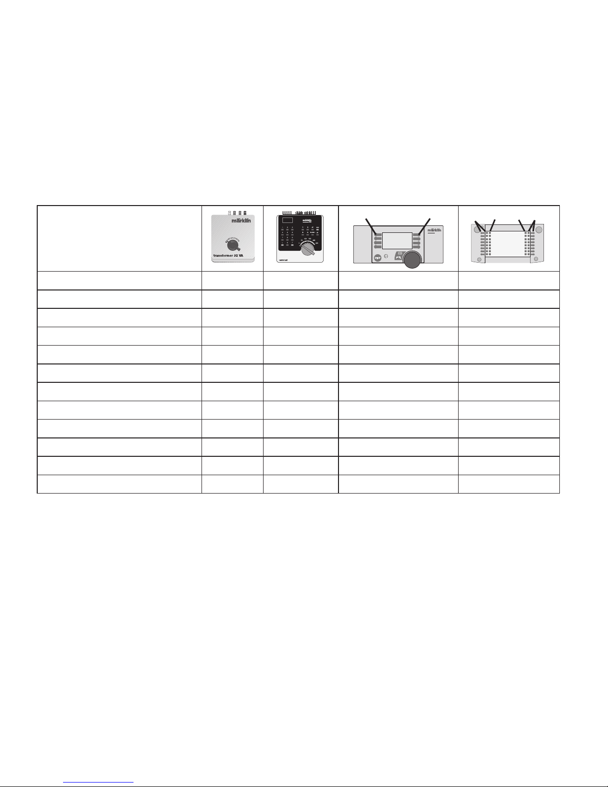
Schakelbare functies
Frontverlichting
aan
1)
function + off Verlichtingstoets
Toets f0
Rookgenerator
2)
aan f1 Toets 7
Toets f1
Telexkoppeling — f2 Toets 6
Toets f2
Rijgeluiden — f3 Toets 3
Toets f3
ABV — f4 Toets 2
Toets f4
Geluid: fluit lang — —
Toets 4
Toets f5
Geluid: Luchtpomp — — Toets 8
Toets f6
Geluid: rangeerhoorn
— —
Toets 5
Toets f7
Piepende remmen uit — — Toets1
Toets f8
Geluid: stom afblazen
— — —
Toets f9
Geluid: kolenscheppen — — —
Toets f10
Geluid: aslade
— — —
Toets f11
central
station
60212
f0
f0f8
f8
STOP
mobile station
systems
1
5
Page 12

12
Función
• Sistemas operativos posibles:
Märklin transformador 6647, Märklin Delta,
Märklin Digital, Märklin Systems.
• Reconocimiento del sistema: automático.
• Códigos disponibles: 01 – 80.
Código de fábrica: 44
• Tecnología mfx para la Mobile Station /
Central Station.
• Nombre de fabrica:
S. 150 X 1518
• Arranque lento variable.
• Frenado lento variable.
• Velocidad máxima variable.
• Fijar parámetros de la locomotora electrónicamente
por el Control Unit, Mobile Station o Central Station.
• Electrónica incorporada de ruidos: solo útil en funcio
namiento con Control Unit o Märklin Systems. Ruidos
suplementarios gobernables.
•
Se puede colocar posteriormente el kit de humo.
• Equipo fumigeno se puede instalor posteriormente
Los trabajos de mantenimiento normales están des-
critos a continuación. Para reparaciones o recambios
contacte con su proveedor Märklin especializado.
Aviso de seguridad
• La locomotora solamente debe funcionar en un
sistema de corriente propio.
Utilizar únicamente transformadores que corres
pondan a la tensión de red local.
En ningún caso utilizar transformadores para una
tensión de red de 220 V o bien 110 V.
• Para el funcionamiento convencional de la loco
motora deben suprimirse las interferencias en la
vía de conexión de la alimentación. Para ello debe
emplearse el set supresor de interferencias 74046. El
set supresor de interferencias no es adecuado para
el funcionamiento en modo digital.
• Observe bajo todos los conceptos, las medidas
de seguridad indicadas en las instrucciones de su
sistema de funcionamiento.
Se excluye todo derecho de garantía, prestación de garantía e
indemnización sobre aquellos productos Märklin en los que se
hubieran montado piezas ajenas no autorizadas por Märklin y/o
sobre aquellos productos Märklin que hayan sido modificados
cuando la piezas ajenas montadas o la modificación sean las
causas de los desperfectos y/o daños posteriormente surgidos.
La persona y/o empresa o el cliente responsable del montaje o
modificación será el responsable de probar y alegar que el montaje de piezas ajenas o la modificación en/de productos Märklin
no son las causas de los desperfectos y/o daños surgidos.
!
Page 13
13
1) La intensidad dependerá de la tensión suministrada.
2) No está incluido en el conjunto de piezas suministradas.
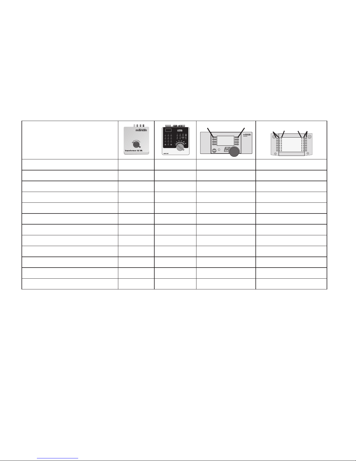
Funciones posibles
Faros frontales
encendido1)function + off Tecla de luz Tecla f0
Generador de humo
2)
encendido
f1
Tecla 7
Tecla f1
Enganche Telex
— f2
Tecla 6
Tecla f2
Ruido de marcha
— f3
Tecla 3
Tecla f3
ABV — f4
Tecla 2
Tecla f4
Ruido del silbido larga
— —
Tecla 4
Tecla f5
Sonido: Bomba de aire
— —
Tecla 8
Tecla f6
Ruido silbato maniobras
— —
Tecla 5
Tecla f7
Desconectar chirrido de los frenos
— —
Tecla 1
Tecla f8
Sonido: soltar vapor
— — — Tecla f9
Sonido: palear carbon
— — — Tecla f10
Sonido: parilla vibratoria
— — — Tecla f11
central
station
60212
f0
f0f8
f8
STOP
mobile station
systems
1
5
Page 14

14
Funzionamento
• Possibili sistemi di funzionamento:
Märklin Transformer 6647, Märklin Delta,
Märklin Digital, Märklin Systems.
• Riconoscimento del tipo di funzionamento:
automatico.
• Indirizzi impostabili: 01 – 80.
Indirizzo di fabbrica: 44.
•
Tecnologia mfx per Mobile Station / Central Station.
• Nome de fabrica: S. 150 X 1518
• Ritardo di avviamento modificabile.
• Ritardo di frenatura modificabile.
• Velocità massima modificabile.
• Regolazione dei parametri della locomotiva elettroni
camente tramite Control Unit, Mobile Station oppure
Central Station.
• Generatore elettronico di suoni incorporato, utiliz
zabile soltanto nel funzionamento con Control Unit
oppure Märklin Systems.
• Suoni aggiuntivi commutabili.
• Apparato fumogeno equipaggiabile in seguito.
Le operazioni di manutenzione che si verificano nel
normale funzionamento sono descritte nel seguito. Per
riparazioni o parti di ricambio Vi preghiamo di rivolgerVi
al Vostro rivenditore specialista Märklin.
Avvertenze per la sicurezza
• Tale locomotiva deve essere impiegata soltanto con
un sistema di funzionamento adeguato per questa.
Impiegare solamente dei trasformatori che corrispondono alle loro tensioni di rete locali.
Non si impieghino in nessun caso dei trasformatori per
una tensione di rete di 220 V o rispettivamente 110 V.
• Per il funzionamento tradizionale della locomotiva
il binario di alimentazione deve essere protetto dai
disturbi. A tale scopo si deve impiegare il corredo
antidisturbi 74046. Tale corredo antidisturbi non è
adatto per il funzionamento Digital.
• Vogliate prestare assolutamente attenzione alle
avvertenze di sicurezza nelle istruzioni di impiego per
il Vostro sistema di funzionamento.
Märklin non fornisce alcuna garanzia, assicurazione e risarcimentodanni in caso di montaggio sui prodotti Märklin di componenti non espressamente approvati dalla ditta. Märklin altresì
non risponde in caso di modifiche al prodotto, qualora i difetti e
i danni riscontrati sullo stesso siano stati causati da modifiche
non autorizzate o dal montaggio di componente esterni da lei
non approvati. L‘onere della prova che i componenti montati e
le modifiche apportate non sono state la causa del danno o del
difetto, resta a carico del cliente o della persona / ditta che ha effettuato il montaggio di componenti estranei o che ha apportato
modifiche non autorizzate.
!
Page 15
15
1) L’intensità dipende dalla tensione di alimentazione applicata.
2) Non incl. nella fornitura.
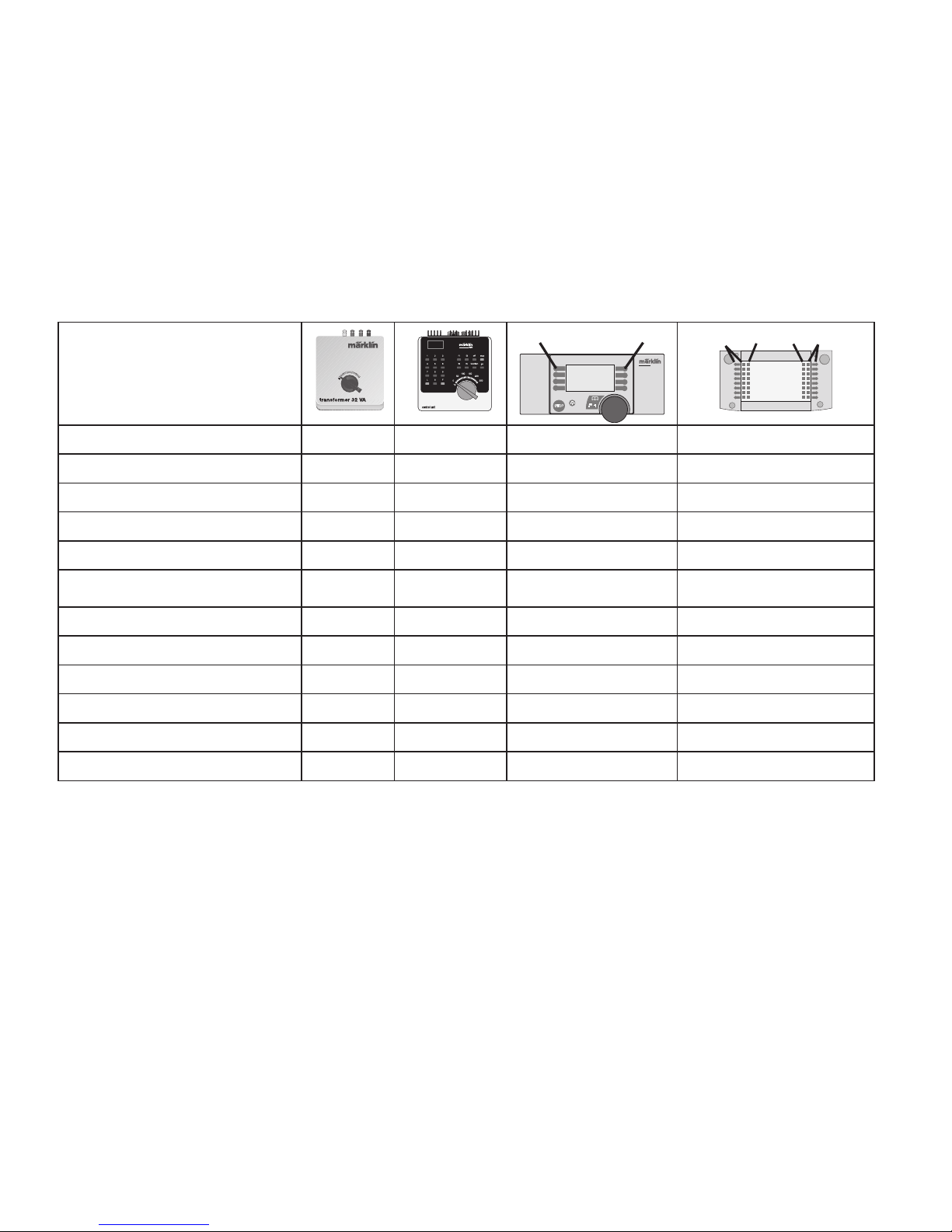
Funzioni commutabili
Illuminazione di testa accesa
1)
function + off Tasto illuminazione Tecla f0
Apparato fumogeno
2)
accesa f1 Tasto 7 Tecla f1
Aggancio Telex
— f2 Tasto 6 Tecla f2
Rumore di marcia
— f3 Tasto 3 Tecla f3
ABV — f4 Tasto 2 Tecla f4
Rumore: Fischio di
segnalazione lunga
— —
Tasto 4
Tecla f5
Compressore dell’aria
— — Tasto 8 Tecla f6
Suono del fischio da manovra
— —
Tasto 5
Tecla f7
Stridore dei freni escluso
— — Tasto 1 Tecla f8
Rumore: scarico del vapore
— — — Tecla f9
Spalatura del carbone — — — Tecla f10
Rumore: griglia vibrante
— — — Tecla f11
central
station
60212
f0
f0f8
f8
STOP
mobile station
systems
1
5
Page 16

16
Funktion
• Möjliga driftsystem:
Märklin Transformer 6647, Märklin Delta,
Märklin Digital, Märklin Systems.
• Driftsättet igenkänns automatiskt.
• Inställbara adresser: 01 – 80.
Adress från tillverkaren:
44.
• Mfx-teknologi för Mobile Station /
Central Station.
• Namn fran tillverkaren:
S. 150 X 1518
• Accelerationsfördröjning kan ändras.
• Bromsfördröjning kan ändras.
• Toppfart kan ändras.
• Elektronisk inställning av lokparametrar via Control
Unit, Mobile Station eller
Central Station.
• Inbyggd ljudelektronik kan endast användas vid drift
med Control Unit eller Märklin Systems.
• Ytterligare ljud kan kopplas.
• Kan efteråt förses med rökgenerator.
Underhållsarbeten som uppstår vid normal användning
beskrivs som följer. Kontakta din Märklinfackhandlare
för reparationer och reservdelar.
Säkerhetsanvisningar
• Loket får endast köras med ett därtill avsett driftsystem.
Använd endast transformatorer som är avsedda
för den nätspänning som tillhandahålls av er
elleverantör. Anslut aldrig en transformator för 220
V nätspänning till 110 V - eller tvärt om.
• Beakta alltid säkerhetsanvisningarna i bruksanvisnin
-
gen som hör till respektive driftsystemet.
• När den motorförsedda lokdelen ska köras med kon-
ventionell drift måste anlutningsskenan vara avstörd.
Till detta använder man anslutningsgarnityr 74046
med avstörning och överbelastningsskydd. Avstör
-
ningsskyddet får inte användas vid digital körning.
Varje form av anspråk på garanti och skadestånd är utesluten
om delar används i Märklin-produkter som inte har godkänts av
Märklin och/eller om Märklin-produkter har modifierats och de
inbyggda främmande delarna resp. modifieringen var upphov till
de därefter uppträdande felen och/eller skadorna. Bevisbördan
för att inbyggnaden av främmande delar i eller ombyggnaden
av Märklin-produkter inte är upphovet till de uppträdande felen
och/eller skadorna, bär den person och/eller företag resp. kund
som är ansvarig för in- och/eller ombyggnaden.
!
Page 17
17
1) Intensiteten varierar med försörjningsspänningens värde.
2) Ingår inte i leveransen.
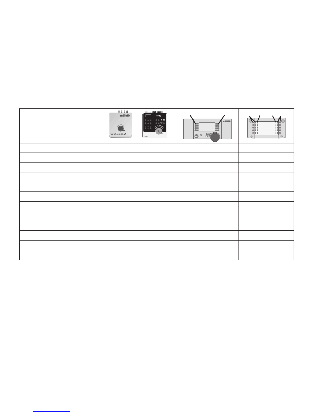
Kopplingsbara funktioner
Frontstrålkastare
till
1)
function + off Belysningsknapp
Knapp f0
Röksats
2)
till f1
Tangent 7
Knapp f1
Telexkoppel — f2
Tangent 6
Knapp f2
Körljud — f3
Tangent 3
Knapp f3
ABV — f4
Tangent 2
Knapp f4
Ljudeffekt: Lokvissla långt — —
Knapp 4
Knapp f5
Ljud: Luftpump — —
Tangent 8
Knapp f6
Ljud: Rangervissla
— —
Knapp 5
Knapp f7
Bromsgnissel, från — —
Knapp 1
Knapp f8
Ljud: Ånga släpps ut
— — —
Knapp f9
Ljud: Kol skyfflas — — —
Knapp f10
Ljud: Skakrost
— — —
Knapp f11
central
station
60212
f0
f0f8
f8
STOP
mobile station
systems
1
5
Page 18

18
Funktion
• Mulige driftssystemer:
Märklin Transformer 6647, Märklin Delta,
Märklin Digital, Märklin Systems.
• Registrering af driftsarten: automatisk.
• Indstillelige adresser: 01 – 80.
Adresse ab fabrik:
44.
• Mfx-teknologi til Mobile Station /
Central Station.
• Navn ab fabrik:
S. 150 X 1518
• Indstillelig opstartforsinkelse.
• Indstillelig bremseforsinkelse.
• Indstillelig maksimalhastighed.
• Elektronisk indstilling af lokomotivparametrene via
Control Unit, Mobile Station eller Central Station.
• Indbygget lydelektronik, kan kun bruges ved drift
med Control Unit eller Märklin Systems.
• Yderligere styrbare lyde.
• Røggenerator kan eftermonteres.
Vedligeholdelsesarbejder ved normal drift er beskrevet
i det efterfølgende. For reparation eller reservedele
bedes De henvende Dem til Deres Märklinforhandler.
Vink om sikkerhed
• Lokomotivet må kun bruges med et driftssystem, der
er beregnet dertil.
Anvend kun transformatorer, der passer til den lokale netspænding. Anvend aldrig transformatorer der
er beregnet til en netspænding på 220 V eller 110.
• Vær under alle omstændigheder opmærksom på de
vink om sikkerhed, som findes i brugsanvisningen for
Deres driftssystem.
• Ved konventionel drift af lokomotivet skal tilslut
ningssporet støjdæmpes. Dertil skal anvendes
støjdæmpningssættet 74046. Støjdæmpningssættet
er ikke egnet til digital drift.
Ethvert garanti-, mangelsansvars- og skadeserstatningskrav er
udelukket, hvis der indbygges fremmeddele i Märklinprodukter,
der ikke er frigivet dertil af Märklin og/eller hvis Märklinprodukter
bygges om og de indbyggede fremmeddele hhv. ombygningen
var årsag til sådanne opståede mangler og/eller skader. Det påhviler kunden hhv. den person og/eller det firma, der er ansvarlig
for ind- og/eller ombygningen, at påvise hhv. bevise, at indbygningen af fremmeddele i, eller ombygningen af Märklinprodukter
ikke var årsag til opståede mangler og/eller skader.
!
Page 19
19
1) Intensitet afhængig af forsyningsspændingens styrke.
2) Medleveres ikke.
Styrbare funktioner
Frontbelysning
til
1)
function + off Belysningsknap
Knap f0
Røggenerator
2)
til f1 Knap 7
Knap f1
Telexkobling — f2 Knap 6
Knap f2
Kørelyd — f3 Knap 3
Knap f3
ABV — f4 Knap 2
Knap f4
Lyd: Lokomotivfløjte langt — —
Knap 4
Knap f5
Lyd: Luftpumpe — — Knap 8
Knap f6
Lyden af en rangerfløjte
— —
Knap 5
Knap f7
Pibende bremser fra — — Knap 1
Knap f8
Lyd: Dampudledning
— — —
Knap f9
Lyd: Skovling av kul — — —
Knap f10
Lyd: Rysterist
— — —
Knap f11
central
station
60212
f0
f0f8
f8
STOP
mobile station
systems
1
5
Page 20

20
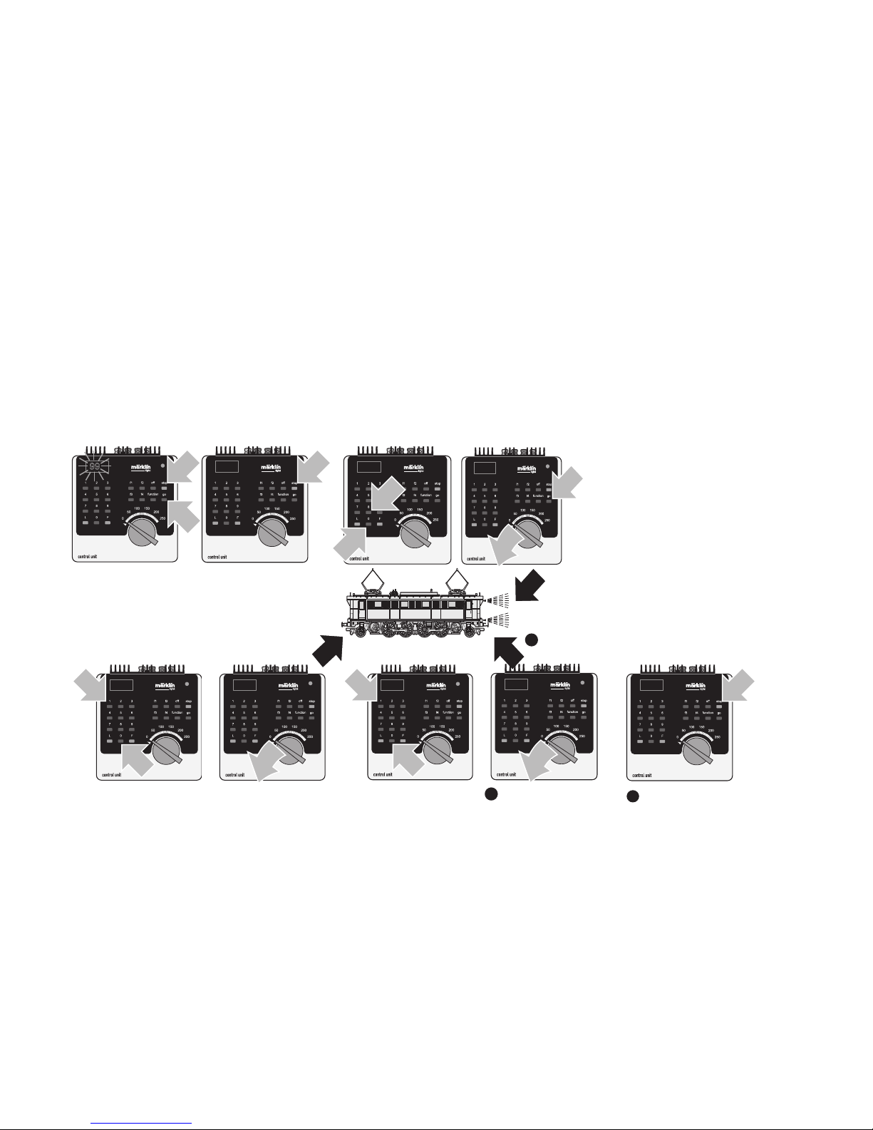
Lokparameter einstellen mit der Control Unit
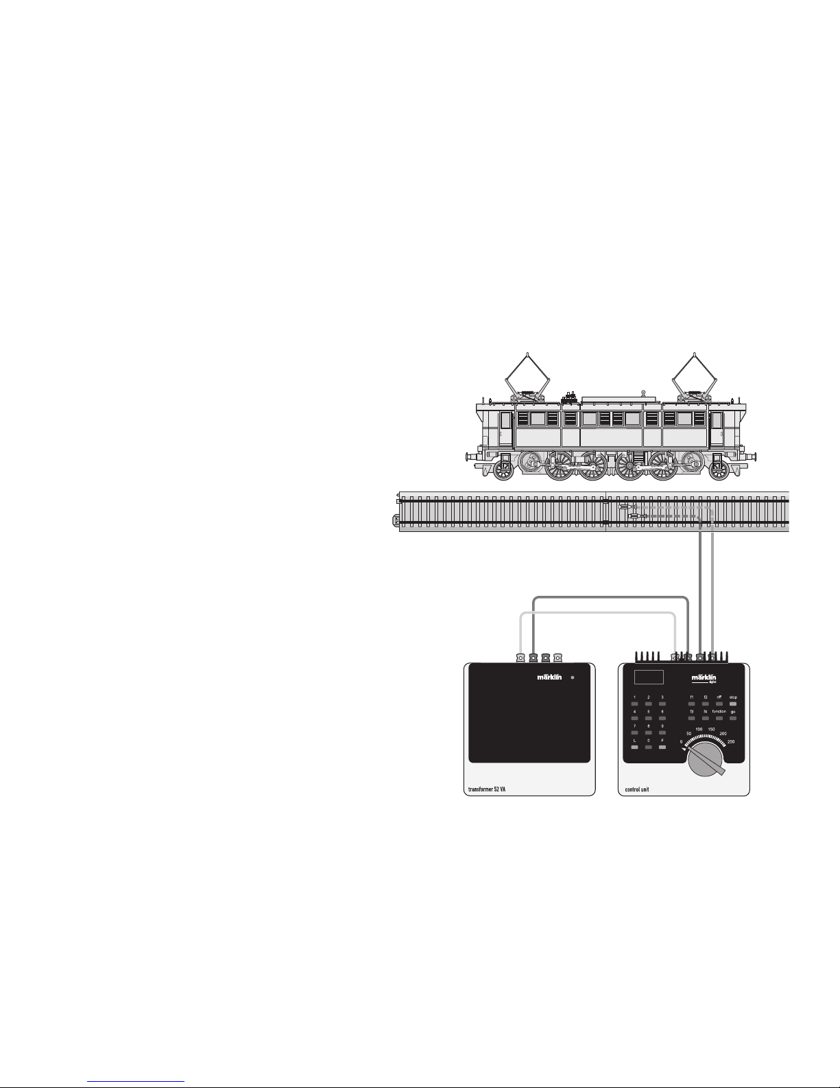
1. Voraussetzung: Aufbau wie Grafik S. 24.
Nur die zu verändernde Lok ist auf dem Gleis.
2. „Stop“- und „Go“-Taste gleichzeitig drücken, bis
„99“ in der Anzeige aufblinkt.
3. „Stop“-Taste drücken.
4. Lokadresse „80“ eingeben.
5. Umschaltbefehl am Fahrregler halten. Während des
Haltens die „Go“-Taste drücken.
6. Licht der Lok blinkt langsam. Wenn nicht, ab Schritt
2 wiederholen.
7. Registernummer für den zu ändernden Para-meter
eingeben (=> Liste auf Seite 26).
8. Fahrtrichtungswechsel betätigen.
9. Licht blinkt schnell
10. Neuen Wert eingeben (=> Liste auf Seite 26).
11. Fahrtrichtungswechsel betätigen.
12. Licht blinkt langsam (Ausnahme Werkreset)
13. Nächste Parametereinstellung ab 6. oder
beenden mit 14.
14. Vorgang beenden mit Drücken der „Stop“Taste. Anschließend Drücken der „Go“-Taste.
Setting Locomotive Parameters with the
Control Unit
1. Requirement: Setup as in diagram on page 24. Only
the locomotive to be changed can be on the track.
2. Press the “Stop” and “Go” at the same time until
“99” blinks in the display.
3. Press the “Stop” button.
4. Enter the locomotive address „80“.
5. Hold the control knob in the reverse direction area.
While holding the control knob here, press the „Go“
button.
6. The headlights on the rail bus will blink slowly. If
they don‘t, repeat Step 2.
7. Enter the register number for the parameter to be
changed (=> List on page 26).
8. Active the change of direction.
9. The headlights will blink rapidly.
10. Enter the new value (=>List on page 26).
11. Active the change of direction.
12. The headlights will blink slowly (exception: factory
reset)
13. Enter the next parameter setting from 6 or end with
14.
14. End the process by pressing the „Stop“ button.
Then press the „Go“ button.
Page 21

21
Réglage des paramètres de la loco avec la
Control Unit
1. Condition: Montage comme sur illustration en page
24. Seule la loco à modifier peut se trouver sur la
voie.
2. Pressez simultanément les touches „Stop“ et „Go“
jusqu’à ce que le nombre „99“ clignote sur l’écran.
3. Pressez la touche „Stop“.
4. Introduisez l’adresse de loco „80“.
5. Maintenir l’ordre de commutation sur le régulateur de
marche. Durant le maintien, appuyer sur la touche
„Go“.
6. Les feux de la locomotive clignotent lentment.
Dans le cas contraire, renouveler l’opération à partir
de l’étape 2.
7. Indiquer le numéro d’enregistrement pour le pa
-
ramètre à modifier (=> liste page 26).
8. Activer l’inversion du sens de marche.
9. Les feux clignotent rapidement.
10. Entrer la nouvelle valeur (=> liste page 26).
11. Activer l’inversion du sens de marche.
12. Les feux clignotent lentement (exception : réinitialisation aux valeurs d’usine)
13. Définition de paramètres suivante à partir du point 6
ou terminer par le point 14.
14. Terminez le processus en pressant la touche
„Stop“. Ensuite, pressez la touche „Go“.
Locparameters instellen met de Control Unit
1. Voorwaarde: opbouw zoals tekening op pagina 24.
Alleen de loc die gewijzigd moet worden op de rails.
2. ”Stop”- en ”Go”-toets gelijktijdig indrukken tot ”99”
in het display oplicht.
3. ”Stop”-toets indrukken.
4. Het adres „80“ invoeren.
5. Omschakelcommando met de rijregelaar vast
houden. Tijdens het vasthouden de toets “Go”
indrukken.
6. De verlichting van de loc knippert langzaam. Indien
dit niet het geval is, vanaf stap 2 opnieuw beginnen.
7. Het registernummer van de te wijzigen parameter
invoeren (=> lijst op pagina 26).
8. Omschakelcommando geven.
9. Verlichting gaat snel knipperen.
10. Nieuwe waarde invoeren (=> lijst op pagina 26).
11. Omschakelcommando geven.
12. Verlichting knippert langzaam (uitgezonderd bij
decoder reset)
13. Volgende parameterinstelling of beëindigen met 14
14. Sessie beëindigen door het indrukken van de toets
“Stop”. Aansluitend de toets “Go” indrukken.
Page 22

22
Parámetros de la locomotora configurables con el
Control Unit
1. Condición previa: montaje como el gráfico
pág. 24. En la vía debe encontrarse solamente la
locomotora a configurar.
2. Apretar simultáneamente la tecla “Stop” y “Go”
hasta que aparece “99” en pantalla.
3. Apretar la tecla “Stop”.
4. Marcar el código de la locomotora „80“.
5. Mantener la orden de conmutación en el regulador
de marcha. Durante la parada, pulsar la tecla „Go“.
6. La luz de la locomotora se enciende con intermiten
-
cia lenta. En caso negativo, repetir desde el paso 2.
7. Introducir el número de registro del parámetro que
se desee modificar (=> Lista en página 26).
8. Activar el cambio de sentido de la marcha.
9. La luz se enciende con intermitencia rápida
10. Introducir un valor nuevo (=> Lista en página 26).
11. Activar el cambio de sentido de la marcha.
12. La luz se enciende con intermitencia lenta (excep
-
ción: se ha realizado un reset en fábrica)
13. Configuración de siguiente parámetro repitiendo a
partir de 6. o terminar con 14.
14. Repetir la operación pulsando la tecla „Stop“. A
continuación, pulsar la tecla „Go“.
Impostazione dei parametri della locomotiva con la
Control Unit
1. Predisposizione: assetto come da schema a pag.
24. Soltanto la locomotiva da modificare si trova sul
binario.
2. Premere contemporaneamente i tasti „Stop“ e
„Go“, fino a che sul visore lampeggia „99“.
3. Premere il tasto „Stop“.
4. Introdurre l’indirizzo della locomotiva „80“.
5. Tenere premuto il comando di commutazione sul re
golatore di marcia. Durante tale pressione, premere
il tasto „Go„.
6. I fanali della locomotiva lampeggiano lentamente. In
caso negativo, si riprenda dal passo 2.
7. Introdurre il numero di registro per il parametro da
modificare (=> elenco a pagina 26).
8. Azionare la commutazione della direzione di marcia.
9. I fanali lampeggiano velocemente
10. Introdurre il nuovo valore (=> elenco a pagina 26).
11. Azionare la commutazione della direzione di marcia.
12. I fanali lampeggiano lentamente (ad eccezione del
ripristino di fabbrica).
13. Impostazione del prossimo parametro ripartendo da
6. oppure terminare con 14.
14. Terminare il procedimento con la pressione del tasto
„Stop„.Successivamente premere il tasto „Go„.
Page 23

23
Lokparametrar ställs in med Control Unit
1. Förutsättning: Montering som visas enligt grafik på
s. 24. Endast det lok som ska ändras ska finnas på
spåret.
2. Både „Stop“- och „Go“-tangenten hålls nedtryckt
tills „99“ blinkar på displayen.
3. „Stop“-tangenten hålls ner.
4. Lokadress „80“ matas in.
5. Tryck ned körkontrollen, som vid ändring av körrikt
ningen. Håll ned knappen och tryck samtidigt på
„Go“-knappen.
6. Lokets strålkastare blinkar långsamt. Om inte
– upprepa steg 2.
7. Ange registernummren för de ändrade parametrar
-
na (=> Se lista på sidan 26).
8. Gör en körriktningsändring.
9. Strålkastarna blinkar snabbt.
10. Ange önskade nya värden (=> Se lista på sidan 26).
11. Gör en körriktningsändring.
12. Strålkastarna blinkar långsamt (Gäller inte vid
genomförd reset)
13. Nästa parameterinställning från steg 6. eller sluta
med steg 14.
14. Avsluta med att trycka på “Stop“-knappen. Tryck
därefter på “Go“-knappen.
Indstilling af lokomotivparametre med Control Unit
1. Forudsætning: Opbygning som på grafikken
s. 24. Kun det lokomotiv, der skal ændres, er på
sporet.
2. Tryk samtidig på „Stop“- og „Go“-tasten, indtil „99“
blinker i displayet.
3. Tryk på „Stop“-tasten.
4. Indtast den lokomotivadresse „80“.
5. Hold omskiftningskommando på køreregulator Tryk
på „Go“-knappen mens der holdes.
6. Lyset på lokomotivet blinker langsomt. Hvis ikke
gentages proceduren fra trin 2.
7. Indtast registernummeret for den parameter, der
skal ændres (=> liste på side 26).
8. Betjen køreretningsskiftet.
9. Lyset blinker hurtigt
10. Indtast den nye værdi (=> liste på side 26).
11. Betjen køreretningsskiftet.
12. Lyset blinker langsomt (undtaget fabriksnulstilling)
13. Udfør næste parameterindstilling fra 6. eller afslut
med 14.
14. Afslut proceduren ved at trykke på „Stop“-knappen
Tryk derefter på „Go“-knappen.
Page 24
24
Lokparameter mit Control Unit ändern.
Changing Locomotive Parameters with the Control Unit.
Modification des paramètres avec la Control Unit.
Locparameter met de Control Unit.
Modificar los parámetros de la locomotora con el Control Unit.
Modifica dei parametri della locomotiva con la Control Unit.
Lokparametrar ändras med Control Unit.
Ændring af lokomotivparametre med Control Unit.
Page 25
25
Lokparameter verändern mit der Control Unit 6021.
Changing Locomotive Parameters with the 6021 Control Unit.
Modification des paramètres de la locomotive avec la Control Unit 6021.
Locparameter wijzigen met de Control Unit.
Modificar los parámetros de la locomotora con el Control Unit 6021.
Modifica dei parametri della locomotiva con la Control Unit 6021.
Lokparametrar ändras med Control Unit 6021.
Ændring af lokomotivparametre med Control Unit 6021.
1
80
1
1
1
99
1
2
80
2
1
01
01
1
1
2
10
10
1
11
14
12
Page 26

26
Parameter • Parameter • Paramètre • Parameter •
Parámetro • Parametro • Parameter • Parameter
Wert • Value • Valeur
• Waarde • Valor •
Valore • Värde •
Værdi
Register • Register •
Registre • Register •
Registro • Registro •
Register • Register
Adresse • Address • Adresse • Adres • Código • Indrizzo •
Adress • Adresse
01 - 8001
Anfahrverzögerung • Acceleration delay • Temoprisation
accélération • Optrekvertraging • Regulación arranque •
Ritardo di avviamento • Igångsättningsreglering •
Opstartregulierung
01 - 6303
Höchstgeschwindigkeit • Maximum speed •
Vitesse maximale • Maximumsneilheid • Velocidad máxima •
Velocità massima • Toppfart • Maksimalhastighed
01 - 6305
Rückstellen auf Serienwerte • Reset to series value • Remettre
aux valeurs de série • Terugzetten naar serie-instellingen •
Restablecer los valores de serie • Pipristinare sui valori di serie
• Återställa till standardvärden • Tibagestil til serieværdien
0808
Bremsverzögerung • Braking delay • Temporisation de freinage • Afremvertraging • Frenado lento • Ritardo di frentura •
Bromsfördröjning • Bremseforsinkelse
01 - 6304
Lautstärke • Volume • Volume haut-parleur • Volume •
Volumen del sonido • Intensit à sonara • Ljudstyrka •
Lydstyrke
63 01 - 63
Page 27

27
Betrieb mit Mobile Station / Central Station
• Lok aufgleisen. Die Lok meldet sich selbsttätig in der
Lokliste an.
• Keine Rückmeldung der Lok, wenn:
bei Mobile Station der Geschwindigkeitsbalken blinkt
bei Central Station das mfx-Symbol unterstrichen ist
• Lok abmelden:
1. Lok vom Gleis entfernen.
2. Lokeintrag löschen.
Eine Adressänderung ist nicht notwendig.
Lokparameter mit der Mobile Station /
Central Station verändern
1. Lok aus der Lokliste auswählen.
2. Zum Untermenü „LOKÄNDERN“ wechseln.
3. Zum Untermenü „VMAX“ (Höchstgeschwindigkeit),
„ACC“ (Beschleunigung), „DEC“ (Bremsen),
„VOL“ (Lautstärke) oder
„RESET“ (Decoder auf Werkeinstellung zurück)
wechseln.
4. Neuen Wert eingeben und übernehmen.
Beachten Sie die Hinweise in der Anleitung zur Mobile
Station / Central Station.
Operation with the Mobile Station /
Central Station
• Set the locomotive on the track. The locomotive
automatically registers itself in the locomotive list.
• The locomotive will not communicate back to the
controller when:
the speed bar on the Mobile Station blinks.
the mfx symbol has a line beneath it on the Central
Station.
• Taking the locomotive out of the locomotive list:
1. Remove the locomotive from the track.
2. Delete the locomotive entry.
It is not necessary to change the address.
Changing Locomotive Parameters with the
Mobile Station
1. Select the locomotive from the locomotive list.
2. Change to the submenu “EDIT LOC”.
3. Go to the submenu „VMAX“ (maximum speed),
„ACC“ (acceleration), „DEC“ (brakes),
„VOL“ (volume) or
„RESET“ (resetting the decoder to factory default
settings).
4. Enter the new value and accept it into the system.
Please note the information in the instructions for the
Mobile Station / Central Station.
Page 28

28
Exploitation avec Mobile Station /
Central Station
• Enrailler la locomotive. La locomotive signale auto
-
matiquement sa présence dans la liste des locos.
•
Pas de rétrosignalisation de la locomotive lorsque :
- la barre de vitesse clignote pour Mobile Station
- le symbole mfx est souligné pour Central Station
• Appeler loco:
1. Enlever loco de la voie.
2. Effacer entrée loco.
Une modification de l’adresse n’est pas nécessaire.
Modification des paramètres de la loco avec la
Mobile Station / Central Station
1. Sélectionnez la loco dans la liste.
2. Allez au sous-menu „MODIF LOC“.
3.
Ouvrir le sous-menu « VMAX » (vitesse maximale),
« ACC » (accélération), « DEC » (freinage),
« VOL » (volume) ou
« RESET » (réinitialisation du décodeur aux valeurs
d’usine).
4. Entrez la nouvelle valeur et acceptez.
Respectez les remarques mentionnées dans l’instruction
accompagnant la Mobile Station / Central Station.
Bedrijf met Mobile Station / Central Station
• Loc op de rails plaatsen. De loc meldt zichzelf aan in
de loclijst.
• Geen terugmelding van de loc als:
bij het Mobile Station de snelheidsbalk knippert
bij het Central Station het mfx-symbool onderstreept is
• Loc afmelden:
1. loc van de rails nemen
2. loc invoer wissen.
Het wijzigen van het adres is niet nodig.
Locparameter wijzigen met het Mobile Station
Central Station
1. Loc uit de loclijst kiezen.
2. Ga naar het nevenmenu ”WIJZIG LOC”.
3. Naar het nevenmenu “VMAX” (maximumsnelheid)
“ACC” (optrekken), “DEC” (afremmen),
“VOL” (volume) of
“RESET” (decoder terugzetten naar fabrieksinstelling) omschakelen.
4. Nieuwe waarde invoeren en overnemen.
Lees ook de opmerkingen in de gebruiksaanwijzing van
het Mobile Station / Central Station.
Page 29

29
Funcionamiento con Mobile Station /
Central Station
• Encarrilar la loc. La loc se introduce por si
misma en la lista de locomotoras.
• No se recibe señalización de respuesta de la loco
motora si:
En la Mobile Station luce intermitentemente la barra
de velocidad
En la Central Station está subrayado el símbolo mfx
• Dar de baja a la loc.:
1º retirar la loc. de la vía
2º borrar los datos de la loc.
No hace falta cambiar el código.
Modificar los parámetros de la locomotora con la
Mobile Station / Central Station
1. Seleccionar la locomotora de la lista de locomotora.
2. Pasar al menú subsidiario “EDIT LOC”.
3. Cambiar al submenú „VMAX“ (Velocidad máxima),
„ACC“ (Aceleración), „DEC“ (Frenado), „VOL“ (Volu
men) o „RESET“ (Devolver decoder a configuración
de fábrica).
4. Introducir el nuevo código y memorizar.
Observe las indicaciones en las instrucciones de la
Mobile Station / Central Station.
Funzionamento con Mobile Station /
Central Station
• Disporre la locomotiva sul binario. La locomotiva si
annuncia automaticamente nell’elenco locomotive.
•
Nessun segnale di ritorno della locomotiva, qualora:
nel caso di Mobile Station lampeggia la barra della
velocità
nel caso di Central Station il simbolo mfx è sottolineato
• Dare congedo alla locomotiva:
1. Rimuovere la locomotiva dal binario.
2. Cancellare l’impostazione della locomotiva.
Non è necessaria una modifica dell’indirizzo.
Modifica dei parametri della locomotiva con la
Mobile Station / Central Station
1. Selezionare la locomotiva dall’elenco locomotive.
2. Commutare al sottomenù „EDIT LOC“.
3. Sul menù sottostante commutare „VMAX„ (velocità
massima), „ACC„ (accelerazione), „DEC„ (frenatura),
„VOL„ (volume sonoro) oppure „RESET„ (riporta il
Decoder alle impostazioni di fabbrica).
4. Introdurre il nuovo valore e accettarlo.
Prestate attenzione alle avvertenze nelle istruzioni della
Mobile Station / Central Station.
Page 30

30
Drift med Mobile Station / Central Station
• Sätt loket på spåret. Loket anmäler sig själv på
loklistan.
• Loket anmäler sig inte när:
Mobile Station hastighetsbalk blinkar
Central Station mfx-symbol är understruken
• Att avregistrera loket:
1. Ta loket från spåret
2. Ta bort loket från loklistan.
En adressändring behövs inte
Lokparametrar ändras med Mobile Station /
Central Station
1. Välj lok från loklistan.
2. Växla till undermenyn „EDIT LOC“.
3.
Byt till resp. Undermeny: “VMAX“ (maxhastighet),
“ACC“ (acceleration), „DEC„ (bromsning),
„VOL„ (ljudstyrka) eller till
„RESET„ (för återställning av dekodern till ursprung
-
lig fabriksinställning).
4. Mata in nytt värde och acceptera.
Glöm ej: Se även i anvisningarna i bruksanvisningen för
Mobile Station / Central Station!
Drift med Mobile Station / Central Station
• Sæt lokomotivet på skinnerne. Lokomotivet registre
-
res automatisk i lokomotivlisten.
• Ingen tilbagemelding fra lokomotivet, når:
hastighedsbjælken blinker ved brug af Mobile
Station
mfx-symbolet er understreget ved brug af Central
Station
• Afmelding af lokomotivet:
1. Tag lokomotivet af skinnerne.
2. Slet lokomotivet fra listen.
Det er ikke nødvendigt med en adresseændring.
Ændring af lokomotivparametre med Mobile Station
/ Central Station
1. Vælg lokomotivet fra listen.
2. Skift til undermenuen „EDIT LOC“.
3. Til undermenu „VMAX“ (maksimalhastighed),
„ACC“ (acceleration), „DEC“ (bremse),
„VOL“ (lydstyrke) eller „RESET“ (nulstille dekoder til
fabriksindstilling).
4. Indtast den nye værdi og overtag den.
Lagttag henvisningerne i vejledningen til Mobile Station
/ Central Station.
Page 31
31
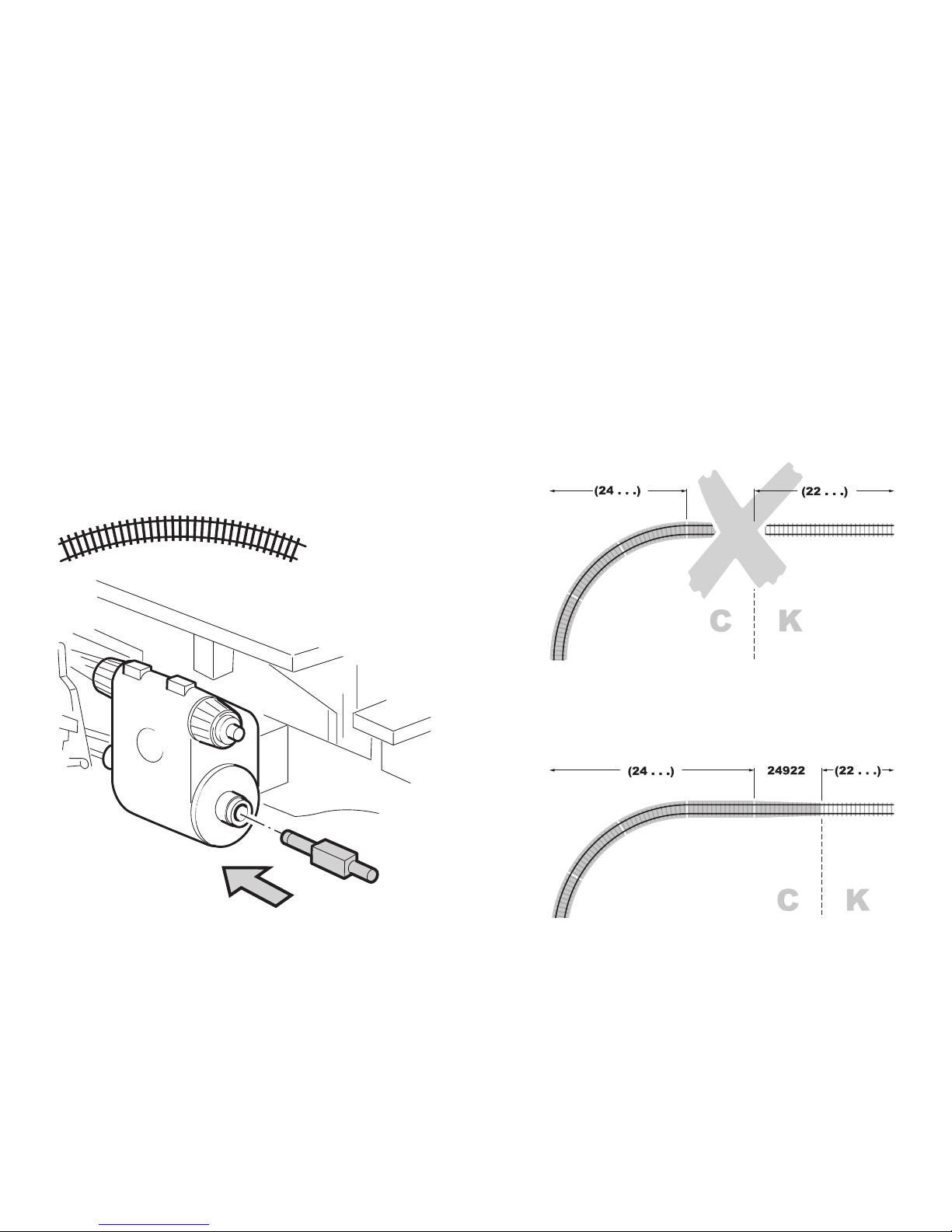
Übergangsgleis / Steigung und Bogenanfang
Transfer rail / gradient and start of bend
Rail de transition / montée et début de courbe
Overgangsrail / Steiging en boogbegin
Vía de transición / cuesta e inicio de la curva
Binario di raccordo / pendenza ed inizio della curva
Övergångsräls / stigning och början av kurva
Overgangsspor / stigning og kurvestart
Radius > 500 mm
Kolbenstangenschutzrohr einsetzen
How to install the cylinder rot protector
Insérer le tube de protection de la lige de piston
Beschermbuis cilinderstang plaatsen
Colocar el tubo protector de la biela
Installazione del tubetto di protezione per
l’asta dello stantuffo
Kolvstångsskyddsröret monteras
Cylinderstang-beskyttelsesør indsættes
Page 32
32
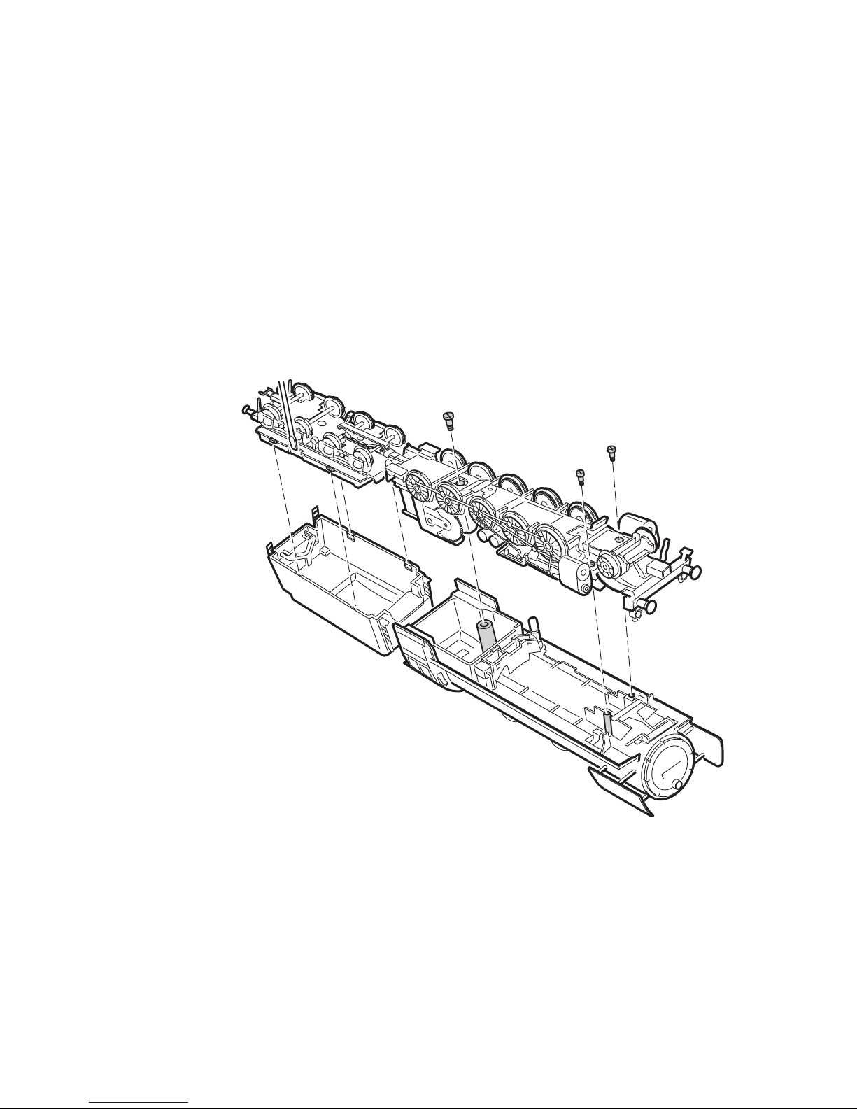
Gehäuse abnehmen
Removing the body
Enlever le boîtier
Kap afnemen
Retirar la carcasa
Smontare il mantello
Kåpan tas av
Overdel tages af
Page 33
33
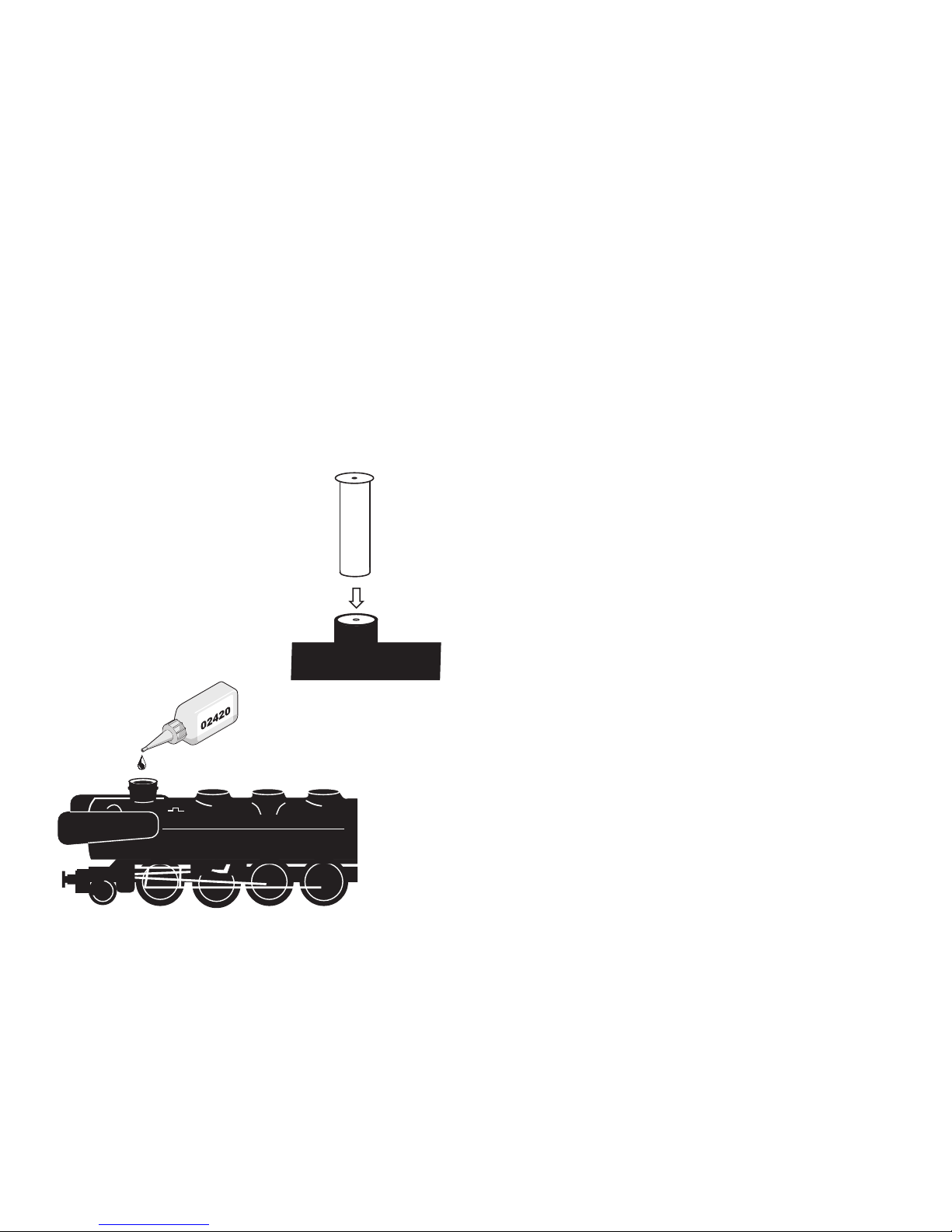
Rauchsatz nachrüstbar
Can be equipped with a smoke unit
Générateur de fumée remplaçable
Met rookgarnituur om te bouwen
El equipo de humo se puede colocar posteriormente
Inserto fumogeno sostituibile
Kan kompletteras med röksats
Røgaggregat kan eftermonteres
Potentielle Fehlerquellen beim Rauchgenerator
• Der Rauchgenerator darf nur maximal halb mit
Rauchöl gefüllt sein.
• Im Rauchgenerator darf sich keine Luftblase befinden.
• Der Anschlussdraht an der Unterseite des Rauchgenerators muss sicheren Kontakt zur Anschlussfe
-
der im Lokomotiv-Fahrgestell besitzen.
Potential Problems with the Smoke Generator
• The smoke generator cannot be filled any more than
halfway with smoke fluid.
• There should not be any air bubbles in the smoke
generator.
• The connecting wire on the underside of the smoke
generator must have a clean contact with the connection field in the locomotive’s frame.
Causes d‘erreurs potentielles Avec le générateur
fumigène
• Le générateur fumigène ne peut pas être rempli de
liquide fumigène au-delà de la moitié du tube.
• Aucune bulle d‘air ne peut se trouver dans le généra
-
teur fumigène.
• Le câble de raccordement raccordé à la face
inférieure du fumigène doit posséder un contact sûr
avec le ressort de connexion dans le châssis de la
locomotive.
7226
02420
Page 34

34
Potentiële storingsoorzaken bij rookgeneratoren
• De rookgenerator mag maximaal half met rookolie
gevuld worden.
• In de rookgenerator mag zich geen luchtbel bevinden.
• De aansluitdraad aan de onderzijde van de rookge
nerator moet een betrouwbaar contact maken met
de contactveer in het locomotief onderstel.
Instrucciones importantes para el buen uso del
fumígeno
• Llenar el cartucho solamente hasta la mitad con
líquido fumígeno.
• Prestar atención que no se forme una burbuja de
aire en el cartucho.
• El hilo tomacorriente de la base debe tener un buen
contacto con el resorte que está en el bastidor de
la locomotora. Si fuera necesario, ajustar el hilo
tomacorriente según la ilustración.
Potenziali origini di guasti nel caso dell’apparato
fumogeno
• L’apparato fumogeno come massimo deve essere
riempito solamente a metà di olio vaporizzabile.
• Nell’apparato fumogeno non deve trovarsi alcuna
bolla d’aria.
• Il conduttore di alimentazione sulla faccia inferiore
dell’apparato fumogeno deve possedere un sicuro
contatto verso la molla di connessione nel telaio
della locomotiva.
Potentiella felkällor på rökgeneratorn
• Rökgeneratorn får maximalt fyllas till hälften med
rökvätska
• I rökgeneratorn får inte finnas någon luftblåsa
• Anslutningstråden på rökgeneratorns undersida
måste ha en säker kontakt med anslutningsfjädern
i lokets chassi. I nödfall måste anslutningstråden
justeras enligt teckningen bredvid.
Potentielle fejlkilder ved røggeneratoren
• Røggeneratoren må maksimalt være halvt fyldt med
røgolie.
• Der må ikke være nogen luftbobler i røggeneratoren.
• Der skal være en god og sikker kontakt mellem
tilslutningstråden på undersiden af røggeneratoren
og tilslutningsfjederen i lokomotivets understel.
Page 35
35
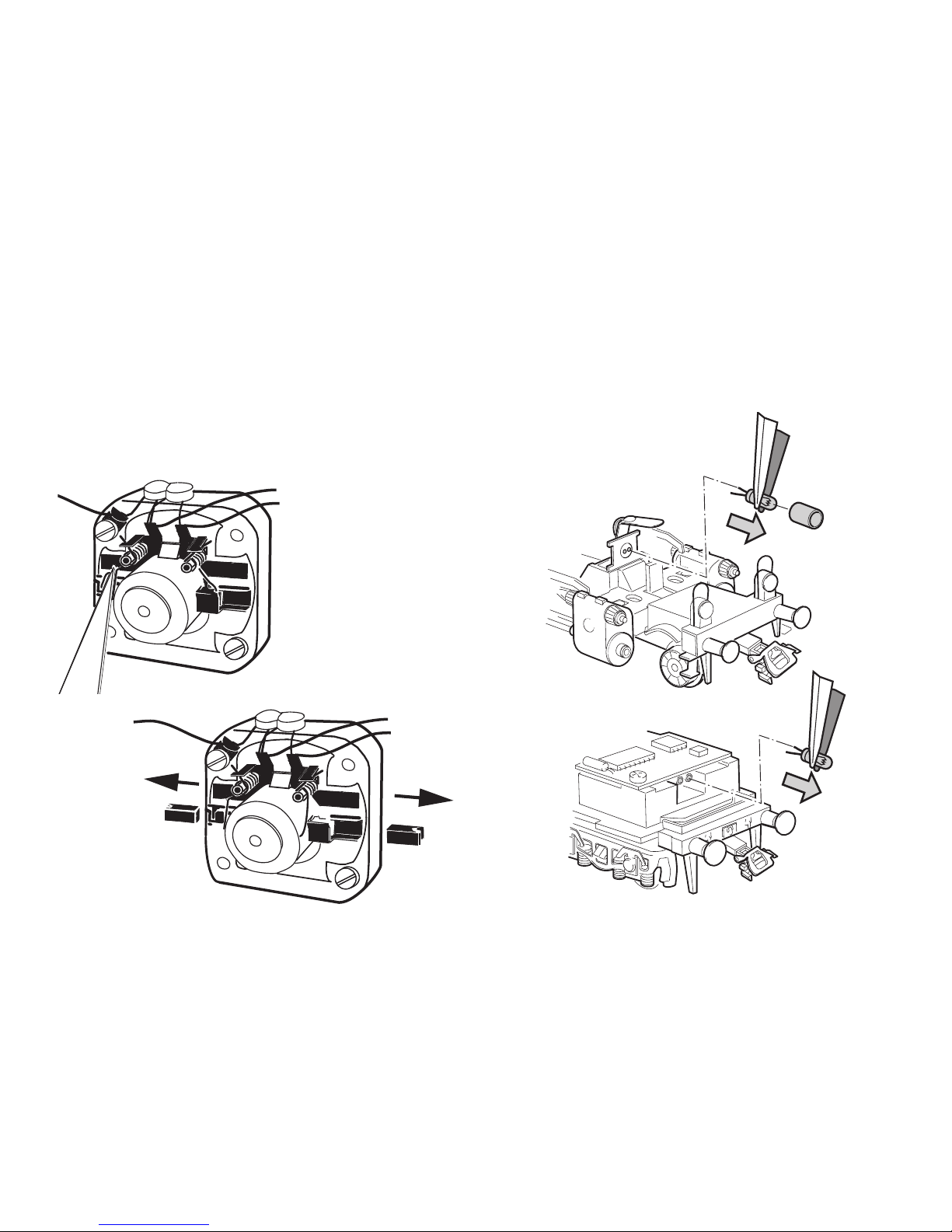
Glühlampen auswechseln
Changing light bulbs
Changer les ampoules
Gloeilamp vervangen
Sustituir la bombilla
Cambiare la lampadina
Glödlampor byts
Elpærer skiftes
610080
Motor-Bürsten auswechseln
Changing motor brushes
Changer les balais du moteur
Koolborstels vervangen
Cambio de las escobillas
Sostituzione delle spazzole del motore
Motorborstar byts
Motorkul udskiftes
��
��
Page 36
36
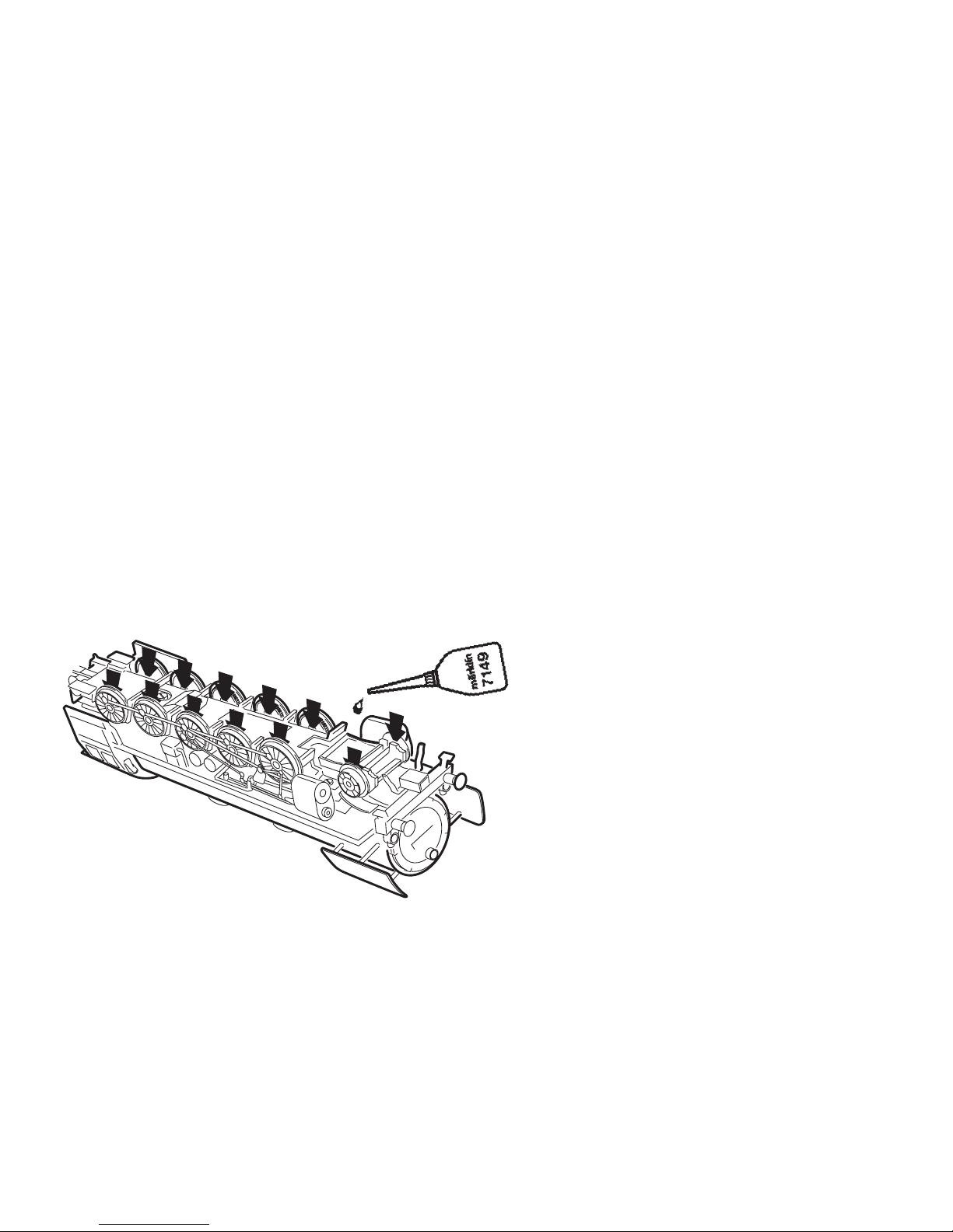
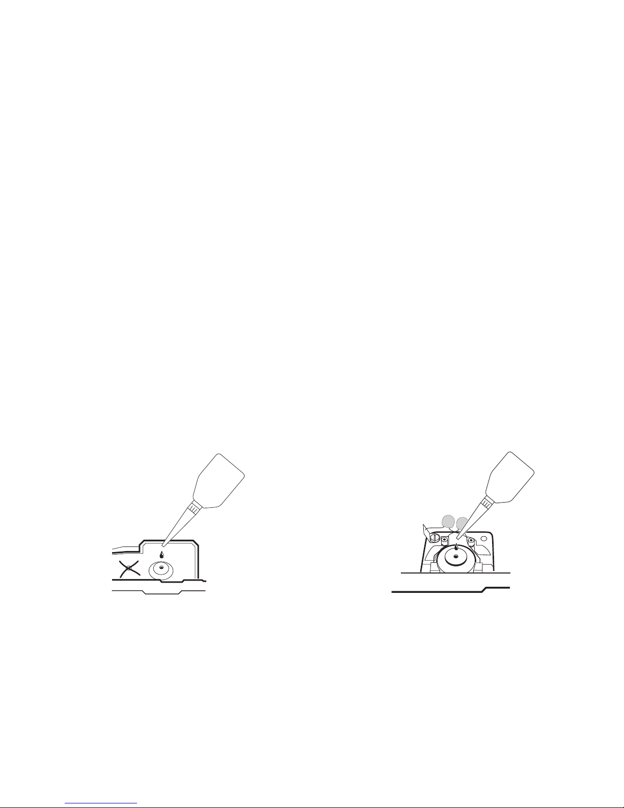
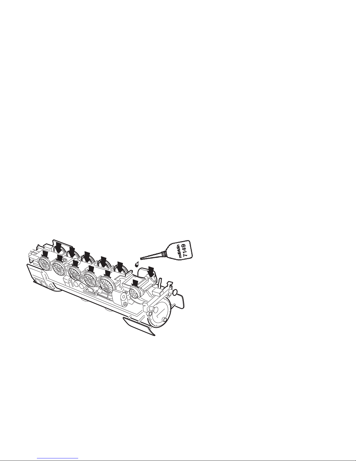
Schmierung nach etwa 40 Betriebsstunden
Wichtige Hinweise zum Ölen der Motorlager:
• Nur sparsam ölen (max. 1 Tropfen). Zuviel Öl führt
häufig zum Verschmieren der Kollektoren und damit
zur Beschädigung des Ankers.
• Nach dem Aufbringen des Öltropfens auf das MotorLager den Anker bewegen. Anschließend überschüssiges Öl mit einem trockenen Tuch entfernen.
• Lokomotive nach Möglichkeit nicht längere Zeit
liegend lagern, da es sonst möglich ist, dass Lageröl
zum Kollektor gelangt und ihn beschädigt.
Lubrication after approximately 40 hours of
Important Information about Oiling the Motor
Bearings:
• Oil sparingly (max. 1 drop). Too much oil frequently
causes the commutator to become dirty and thereby
leads to damage to the armature.
• After you have placed a drop of oil on the motor
bearings, move the armature back and forth a little.
Now remove the excess oil with a dry cloth.
• If possible, do not store the locomotive for long
periods of time on its side, because it is possible
that the bearing oil will get into the commutator and
damage it.
Page 37
37
Graissage après environ 40 heures de marche
Remarque importante au sujet de la lubrification
des paliers du moteur:
• Lubrifiez en très petite quantité (1 goutte max.). Trop
d‘huile entraîne souvent l‘encrassement du collecteur et à des dommages à l‘induit.
•
Une fois la goutte d‘huile déposée sur le palier de moteur, faites tourner l‘induit. Ensuite, essuyez le surplus
d‘huile à l‘aide d‘un chiffon sec.
• Si possible, ne pas laisser la locomotive couchée
trop longtemps car il peut arriver que l‘huile emma
gasinée dans les paliers parvienne dans l‘induit et
l‘endommage.
Smering na ca. 40 bedrijfsuren
Belangrijke opmerking voor het oliën van het mo-
torlager:
• Slechts spaarzaam oliën (max. 1 druppel). Te veel
olie leidt vaak tot versmeren van de collector en
daarmee tot beschadiging van het anker.
• Na het aanbrengen van de oliedruppel op het mo
torlager het anker ronddraaien. Aansluitend met een
droge doek de overvloedige olie verwijderen.
• Locomotief indien mogelijk niet langere tijd, liggend
op de zijkant, opslaan, aangezien het dan mogelijk is
dat de olie van het motorlager de collector bereikt en
deze beschadigt.
!
Page 38
38
Engrase a las 40 horas de funcionamiento
Indicaciones importantes acerca del engrase de los
cojinetes del motor:
• Engrasar poco (máx. 1 gota). Demasiado aceite
ensucia el colector y llega a dañar el rotor.
• Una vez colocada la gota de aceite, mover el rotor. A
continuación quitar el aceite sobrante con un paño
seco.
• No guardar las locomotoras tumbadas durante
mucho tiempo. Es posible que el aceite llegue hasta
el colector y lo dañe.
Lubrificazione dopo circa 40 ore di funzionamento
Importanti avvertenze per la lubrificazione dei cus-
cinetti del motore:
• Si lubrifichi soltanto con parsimonia (al max. 1 goc
-
cia). Troppo olio conduce spesso a un insudiciamen
-
to del collettore e di conseguenza al danneggiamen
-
to del rotore.
• Dopo l’applicazione della goccia di olio ai cuscinetti
del motore, si faccia muovere il rotore. Al termine, si
elimini l’olio in eccedenza con un panno asciutto.
• A seconda delle possibilità, non si lasci giacente la
locomotiva per un tempo alquanto lungo, poiché
altrimenti è possibile che l’olio dei cuscinetti arrivi sul
collettore e lo danneggi.
Page 39
39
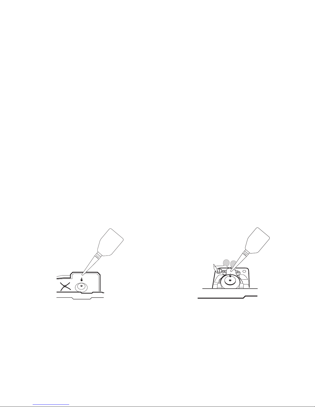
Smörjning efter ca. 40 driftstimmar
Viktiga råd till smörjning av motorlagren:
• Smörj endast sparsamt (max 1 droppe). För mycket
olja leder till nedsmutsning av kollektorerna och
därmed skadas ankaret.
• Snurra ankaret när oljedroppen har placerats på
motorlagret. Torka bort överflödig olja med en torr
trasa.
• Loket bör inte förvaras liggande under längre tid,
eftersom i så fall lagerolja kan hamna i kollektorn och
skada denna.
Smøring efter ca. 40 driftstimer
Vigtige henvisninger vedr. smøring af motorleje:
• Giv kun lidt olie (maks. 1 dråbe). For meget olie fører
ofte til indsmøring af kollektorerne og dermed til
beskadigelse af ankeret.
• Efter anbringelse af oliedråben på motorlejet skal
ankeret bevæges. Til slut fjernes overskydende olie
med en tør klud.
• Hvis det er muligt, skal det undgås at opbevare
lokomotiver i liggende stilling i længere tid, ellers
kan det ske, at lejeolien kommer ind i kollektoren og
beskadiger den.
!
Page 40
40
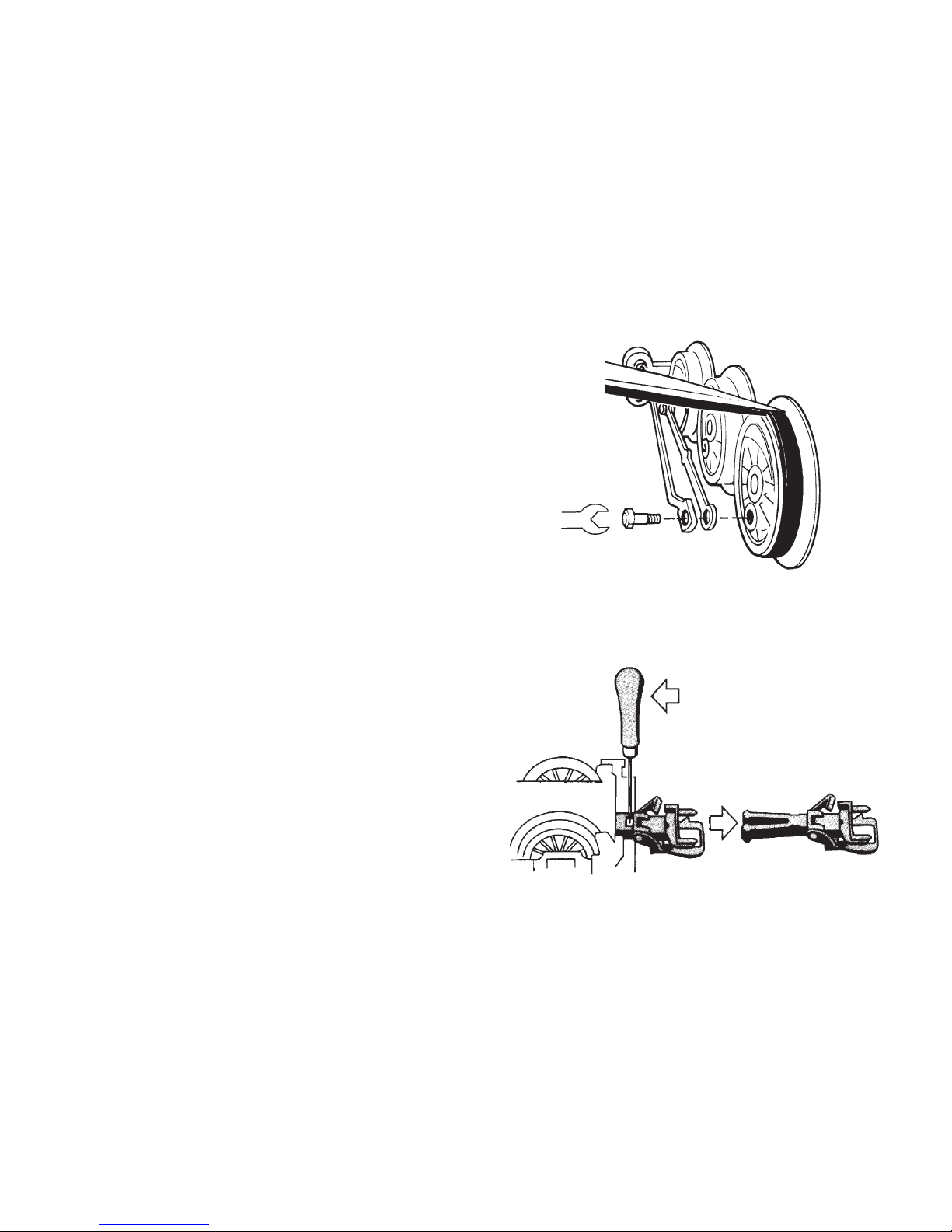
Haftreifen auswechseln
Changing traction tires
Changer les bandages d’adhérence
Antislipbanden vervangen
Cambio de los aros de adherencia
Sostituzione delle cerchiature di aderenza
Slirskydd byts
Friktionsringe udskiftes
Kupplung austauschen
Exchanging the close coupler
Remplacement de l’attelage court
Omwisselen van de kortkoppeling
Enganches cortos
Sostituzione del gancio corto
Utbyte av kortkoppel
Udskiftning af kortkoblingen
7153
701 630
2,5 mm
Page 41
41
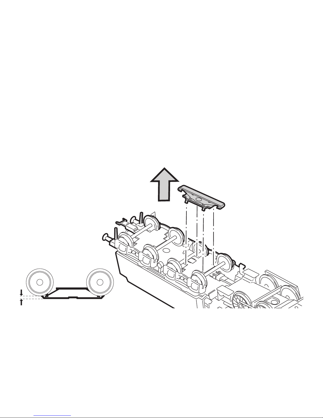
Schleifer auswechseln
Changing the pickup shoe
Changer le frotteur
Vervangen van het sleepcontact
Cambio del patín toma-corriente
Sostituzione del pattino
Byt släpsko
Udskiftning af slæbesko
2 mm
206 370
Page 42
42
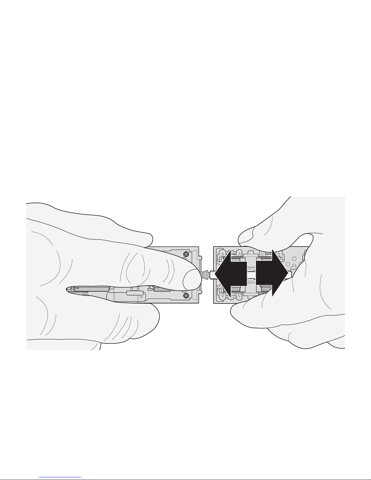
Kurzkupplung zwischen Lok und Tender verstellbar
Close coupling between locomotive and tender is adjustable
Attelage court réglable entre locomotive et tender
Kortkoppeling tussen loc en tender is verstelbaar
El enganche corto ajustable entre locomotora y ténder
Aggancio corto regolabile tra locomotiva e tender
Kortkopplet mellan lok och tender kan regleras
Kortkobling mellem lok og tender indstillelig
Page 43

43
Wichtig:
Im Fahrbetrieb (rmin = 360 mm): Lok und Tender auf
maximalen Abstand einstellen. Nur bei der Präsentation
z.B. in einer Vitrine kann der Abstand zwischen Lok und
Tender minimiert werden.
Important:
In regular layout operation (required minimum radius = 360
mm / 14-3/16”): Set the locomotive and the tender for the
maximum spacing. The spacing between the locomotive and
the tender can be reduced to the minimum only when the
model is on display such as in a display case.
Important:
En exploitation (rmin = 360 mm): Régler l’écart entre locomotive et tender à la valeur maximale. Ne régler l’écart sur une
valeur inférieure que pour la présentation, par exemple dans
une vitrine.
Belangrijk:
In het rijbedrijf (rmin = 360 mm): loc en tender op de
maximale onderlinge afstand instellen. Alleen bij een
presentatie bijv. in een vitrine kan de afstand tussen loc
en tender geminimaliseerd worden.
Importante:
En funcionamiento: (rmin = 360 mm): regular la distan
cia entre la locomotora y el ténder al máximo.Solo para
presentaciones, p.e. en vitrinas, se puede acortar la
distancia entre la locomotora y el ténder.
Importante:
Nell’esercizio di marcia (rmin = 360 mm): regolare loco
-
motiva e tender per la massima distanza. La distanza tra
locomotiva e tender può venire ridotta al minimo soltanto
in caso di esposizione, ad es. in una vetrina.
Viktigt:
Ställ in loket och tendern på maximalt avstånd (rmin
= 360 mm) under körning. Endast vid presentation, t
ex i ett vitrinskåp kan avståndet mellan lok och tender
minimeras.
Vigtigt:
I køredrift (rmin = 360 mm): Indstil lokomotivet og tende
ren til maksimal afstand. Afstanden mellem lokomotivet
og tenderen kan kun minimeres ved udstilling, f.eks. i en
vitrine.
Page 44
44
20
10
9
4
11
10
5
10
7
1
6
10
14
37
43
35
42
28
21
22
23
25
24
26
27
29
30
46
45
39
40
41
43
42
34
36
38
43
44
51
12
53
52
13
50
48
47
49
31
14
15
16
17
38
19
18
39
40
41
43
44
33
32
8
3
2
Details der Darstellung
können von dem Modell
abweichen
Page 45

45
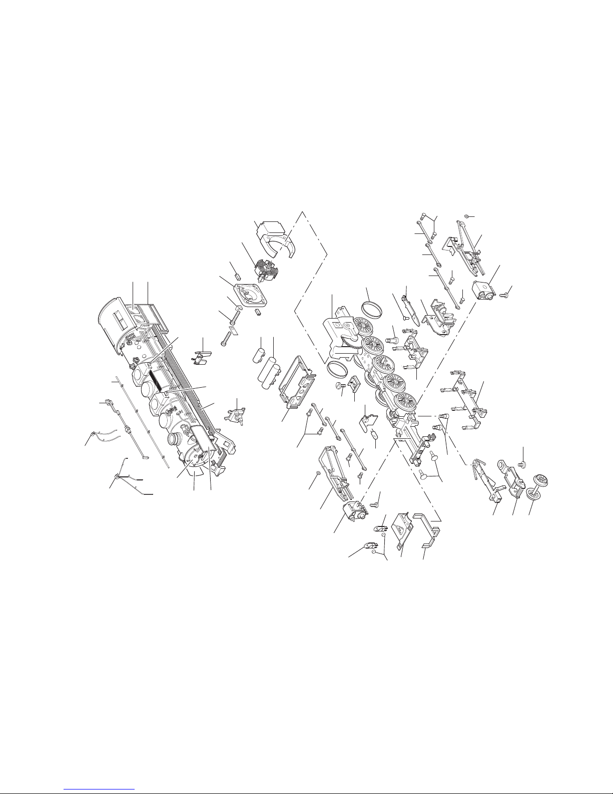
1 Aufbau, komplett 121 815
2 Windleitblech links —
3 Windleitblech rechts —
4 Griffstange 465 710
5 Kesselstütze 482 750
6 Umlauf 121 818
7 Seitenfenster links 209 496
Seitenfenster rechts 209 497
8 Rauchkammertür 121 816
9 Steuerstange 465 620
10 Sandfallrohre 231 321
11 Innen-Triebwerk 208 168
12 Zylinderansatzschraube 753 100
13 Zylinderansatzschraube 753 140
14 Laterne 465 020
15 Linse 761 600
16 Rahmenabdeckung vorn 208 199
17 Lichtkörper 464 830
18 Federplatte 208 186
19 Glühlampe 610 080
20 Druckluftbehälter 208 196
21 Hilfsluftbehälter 208 197
22 Feldmagnet 389 000
23 Anker 386 820
24 Motorschild 386 940
25 Motorbürsten 601 460
26 Lötfahne 231 470
27 Zylinderschraube 784 980
28 Gestängeattrappe 208 202
29 Treibgestell 121 825
mit
30 Haftreifen 7 153
31 Puffer 229 241
32 Zylinderschraube 750 200
33 Isolierplatte 225 877
34 Gestänge links 229 246
35 Gestänge rechts 229 242
36 Zylinder links 343 640
37 Zylinder rechts 343 620
38 Linsenschraube 786 750
39 Kuppelstange 229 248
40 Kuppelstange 200 064
41 Kuppelstange 229 249
42 Sechskantmutter 499 830
43 Sechskantansatzschraube 499 840
44 Sechskantansatzschraube 499 850
45 Zugstange 464 820
46 Bolzen 298 020
47 Laufgestellrahmen 208 201
48 Laufradsatz 200 062
49 Deichsel 208 187
50 Zylinderschraube 750 180
51 Rahmenabdeckung hinten 208 198
52 Bremsattrappe 208 195
53 Bremsattrappe 499 820
Page 46
46
56
54
55
61
62
60
59
66
65
69
68
67
74
71
70
72
73
75
72
71
70
64
63
57
58
Details der Darstellung
können von dem Modell
abweichen
Page 47

47
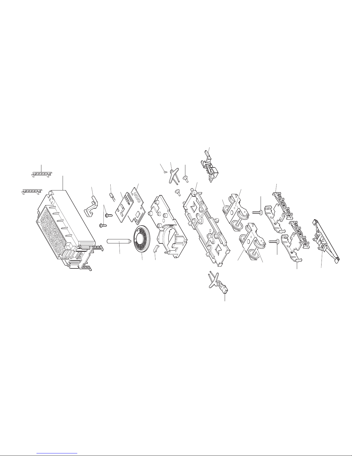
54 Aufbau Tender 121 823
55 Lichtkörper 203 128
56 Leiter 229 400
57 Lautsprecher 508 617
58 Haltebügel 209 693
59 Leiterplatte Schnittstelle 119 389
60 Decoder 129 116
61 Linsenschraube 786 750
62 Glühlampe 610 080
63 Haltebügel 222 005
64 Deichsel 463 640
65 Kupplungslager 210 137
66 Rastbolzen 218 951
67 Kupplung 210 133
68 Boden 226 717
69 Puffer 229 233
70 Lagerblech 369 760
71 Laufradsatz 700 190
72 Zylinderschraube 750 230
73 Drehgestellblende 208 173
74 Drehgestellblende 400 830
75 Schleifer 206 370
Page 48

123133/0308/SmEf
Änderungen vorbehalten
© Gebr. Märklin & Cie. GmbH
Gebr. Märklin & Cie. GmbH
Postfach 860
D-73008 Göppingen
www.maerklin.com
This device complies with Part 15 of the FCC Rules.
Operation is subject to the following two conditions:
(1) This device may not cause harmful interference, and
(2) this device must accept any interference received, including
interference that may cause undesired operation.
 Loading...