

Page 1
CERTIFIKAT
Bedienungsanleitung
Instruction
Instructions de Service
8.869110.412 131683 0.600 0808 Fa
Änderungen der technischen Ausführungen vorbehalten.
We reserve the right to make technical alterations without prior notice.
Modifications de constructions réservées.
쏐
Für drinnen und draussen - For indoors and outdoors
Achtung!
Verpackung und Betriebsanleitung aufbewahren!
Nicht für Kinder unter 8 Jahren geeignet, modellbedingt besteht Quetschund Klemmgefahr durch Antriebsgestänge der Lok.
Nicht für Kinder unter 8 Jahren geeignet, wegen funktions- und modellbedingter scharfer Kanten und Spitzen.
Attention!
This product is not for children under 8 years of age. It has moving parts
that can pinch and bind.
This product is not for children under 8 years of age. This product has
small parts, sharp parts and moving parts.
Attention!
Veuillez conserver l’emballage et le mode d’emploi!
Ne convient pas aux enfants de moins de 8 ans. L’embiellage de la locomotive peut pincer les doigts de jeunes enfants.
Ne convient pas aux enfants de moins de 8 ans. Présence de petits éléments susceptibles d’être avalés.
Attenzione!
Conservare l’imballo e le istruzioni per l’uso!
Non adatto a bambini di età inferiore agli 8 anni poiché vi è possibilità a
pericolo di schiacciamento delle dita quando il treno è in funzione.
Non adatto a bambini di età inferiore agli 8 anni in quanto le strutture presentano spigoli vivi e punte accuminate.
Atención!
Guardar el carton de embalaje y las Instrucciones para el uso!
No adecuado para niños menores de 8 años. Según el modelo, existe el
peligro de sufrir contusiones o de cogerse los dedos a causa del varillaje
de accionamiento de la locomotora. No adecuado para niños menores de
8 años, debido a cantos y puntas peligrosas condicionadas por la función
o el modelo.
Attentie!
Verpakking en gebruiksaanwijzing bewaren!
Niet geschikt voor kinderen onder de 8 jaar omdat deze loc aandrijfstangen bezit waaraan kinderen zich kunnen bezeren.
Niet geschikt voor kinderen onder de 8 jaar omdat dit model funktionele
scherpe kanten en punten bezit.
DAS VORBILD
Viele Nebenstrecken haben ein geringes Fahrgastaufkommen, so daß
sich normale Personenzüge nicht
rentieren. Hier werden oft
Schienenbusse eingesetzt - Personenwagen mit eigenem Antrieb.
Viele Schienenbusse führen einen
Steuerwagen mit, um die Kapazität
zu erhöhen. Auf manchen Strecken
wurden sogar ein oder zwei
Güterwagen angehängt, so daß ein
kurzer gemischter Zug entstand
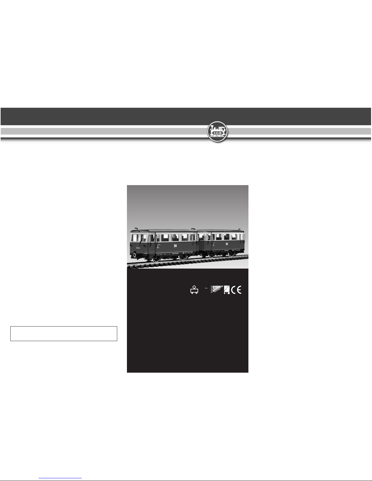
DR Triebwagen + Steuerwagen
VT 133
Art.Nr. 29650
DC
0-24 V
...
GARANTIE
Nos produits de qualité supérieure sont le
résultat du mariage de l’innovation et de la
technologie. À l’instar d’une montre précieuse, tous les composants sont fabriqués
à la main par nos artisans méticuleux. Un
programme rigoureux d’assurance de la
qualité, de la sélection des matériaux à
l’assemblage et aux vérifications avant
sortie des ateliers, garantissent un haut
niveau de qualité constante. Afin d’obtenir
la plus grande satisfaction de ce produit,
veuillez lire la fiche d’instructions ainsi que
cette garantie.
Gebr. Märklin & Cie, GmbHgarantit ce produit, à l’échelle mondiale, contre tout vice
de matière et de fabrication, pendant deux
ans à partir de la date d’achat par l’acheteur original, si le produit a été acheté chez
un détaillant autorisé.
Si vous demandez un recours en garantie
pour un motif jugé recevable, joignez la
preuve de l’achat chez un détaillant autorisé et nous réparerons ou remplacerons le
produit à notre discrétion. S’il s’avère
impossible de réparer ou de remplacer le
produit, nous rembourserons, à notre discrétion, tout ou partie du prix d’achat.
Vous pouvez disposer d’autres droits
légaux en plus de cette garantie, en particulier en cas de vice de matière.
Pour initier une demande de règlement au
titre de cette garantie, veuillez ramener le
produit, avec la preuve d’achat, à votre
revendeur autorisé. Pour trouver l’adresse
d’un revendeur autorisé, veuillez entrer en
rapport avec l’un des Centres de service
après-vente ci-dessous. Vous pouvez également renvoyer le produit, avec la preuve
d’achat, directement à l’adresse ci-dessous. L’expéditeur est responsable des
frais d’expédition, de l’assurance et des
frais de douane.
Gebr. Märklin & Cie. GmbH
LGB Service-Abteilung
Witschelstraße 104
90431 Nürnberg
Deutschland
Téléphone: +49 (911) 83707-38
Veuillez bien noter que :
- Cette garantie ne couvre pas les dommages résultat d’une utilisation inadéquate,
ni de modification/réparation inadéquate.
Cette garantie ne couvre pas l’usure normale.
- Les transformateurs et commandes sont
conformes aux normes rigoureuses CE et
UL et ne peuvent être ouverts et réparés
que par le fabricant. Toute violation à cet
égard entraînera la perte impérative de
tous les droits de garantie et un refus de
toutes réparations, quelles qu’elles
soient.
- États-Unis uniquement : Cette garantie
vous donne des droits légaux spécifiques,
et vous pouvez également avoir d’autres
droits qui varient d’un État à l’autre.
Nous sommes très fiers de nos produits et
nous vous souhaitons des années d’amusement inoubliables avec votre hobby qui
est également le nôtre.
WARRANTY
This precision product is made using quality designs and technology.
Like a fine timepiece, it has been crafted by
hand. Constant monitoring of materials and
assembly, together with final testing,
ensure a consistent level of high quality. To
get the most enjoyment from this product,
we encourage you to read the instructions
and this warranty.
Gebr. Märklin & Cie, GmbH warrant this
product worldwide for two years from the
date of original consumer purchase against
defects in materials and workmanship, if
purchased from an authorized retailer.
If you have a valid warranty claim, including proof of purchase from an authorized
retailer, we will repair or replace the product at our discretion. If it is impossible to
repair or replace the product, we will
refund all or a reasonable portion of the
purchase price at our discretion.
Of course, you may have other legal rights
independent of this warranty, particularly in
the case of material defects.
To make a claim under this warranty,
please bring the product, with the proof of
purchase, to your authorized retailer. To
find an authorized retailer, please contact
the address below. You may also send the
product, with the proof of purchase, the
service departments below. You are
responsible for any shipping costs, insurance and customs fees.
Gebr. Märklin & Cie. GmbH
LGB Service-Abteilung
Witschelstraße 104
90431 Nürnberg
Deutschland
Telephone: +49 (911) 83707-38
Please note:
- This warranty does not cover damage
caused by improper use or improper
modifications/repairs. This warranty does
not cover normal wear and tear.
- Transformers and controls are subject to
strict CE and UL regulations and may only
be opened and repaired by the manufacturer. Any violations automatically void
this warranty and prevent any repair by
us.
- U.S. only: This warranty gives you specific legal rights, and you may
also have other rights which vary from
State to State.
We are very proud of our products, and all
of us sincerely hope they give you many
years of enjoyment!
GARANTIE
Unsere Produkte sind Präzisionswertarbeit
in Design und Technik. Wie bei einer wertvollen Uhr werden feinstmechanische
Präzisionsteile von Hand gefertigt.
Permanente Material-, Fertigungs- und
Endkontrollen vor der Auslieferung garantieren unser gleichbleibend hohes
Qualitätsniveau. Um wirklich ungetrübten
Spaß zu haben, lesen Sie bitte diese
Garantie und Bedienungsanleitung.
Gebr. Märklin & Cie, GmbH gewährt auf
dieses Produkt weltweit eine Garantie von
2 Jahren ab dem Erstkauf für Fehlerfreiheit
von Material und Funktion, sofern dieses
Produkt mit Kaufbeleg bei einem von uns
autorisierten Fachhändler erworben wurde.
Bei berechtigten Reklamationen innerhalb
von 2 Jahren nach Kaufdatum werden wir
gegen Vorlage des entsprechenden
Kaufbelegs nach unserem Ermessen kostenlos nachbessern oder kostenlosen
Ersatz liefern. Sollten Nachbesserung oder
Ersatzlieferung unmöglich sein, so räumen
wir Ihnen nach unserem Er messen eine
angemessene Minderung ein oder erstatten Ihnen statt dessen den Kaufpreis
zurück.
Unabhängig von diesen Garantie leistungen
bleiben Ihnen selbstverständlich Ihre
gesetzlichen Ansprüche insbesondere
wegen Sachmängel erhalten.
Um einen Anspruch auf Garantieleistung
geltend zu machen, übergeben Sie bitte
das beanstandete Produkt, zu sammen mit
dem Kaufbeleg, Ihrem von uns autorisierten Händler. Um einen autorisierten
Händler zu finden, wenden Sie sich bitte an
die unten aufgeführte Adresse. Sie können
das Produkt auch, zusammen mit dem
Kauf beleg, an die unten aufgeführte
Serviceabteilung einschicken. Die Ein sendung erfolgt zu Ihren Lasten.
Gebr. Märklin & Cie. GmbH
LGB Service-Abteilung
Witschelstraße 104
90431 Nürnberg
Deutschland
Telefon (0911) 83707-38
Bitte beachten Sie:
- Für Schäden durch unsachgemäße Be handlung oder unsachgemäßen Fremdeingriff sowie für Verschleißteile be steht
kein Garantieanspruch.
- Transformatoren und Regler unterliegen
strengen CE-UL-Vorschriften und dürfen
nur vom Hersteller geöffnet und repariert
werden.
Zuwiderhandlungen bewirken zwingend
Garantieverlust und generelle Reparatur verweigerung.
- Nur für USA: Diese Garantie gibt Ihnen
genau definierte Rechte. Weiterhin verbleiben Ihnen unter Umständen je nach
Bundesstaat weitere Rechte.
Wir sind sehr stolz auf unsere Produkte.Wir
alle hoffen, dass sie Ihnen viele Jahre lang
Freude bereiten.
Page 2
43
DAS MODELL
Allgemeines
Dieses Modell gehört zum LGBProgramm mit mehr als 600 hochwertigen Produkten. Das Programm
umfasst: Fahrzeuge, Gleissystem
und Zubehör in der Baugröße G
sowie das LGB-Mehrzugsystem-MZS.
Weitere Informationen über das
komplette LGB-Programm finden Sie
im großen LGB-Katalog.
Sicherheitshinweis
Die Sicherheitshinweise in dieser
Betriebsanleitung sind zu beachten!
Ausführung
- wetterfestes Modell mit hoher
Detaillierung.
- reichhaltige Ausstattung.
Ausstattung
- Stromabnehmer am Triebwagen 4
- Achsen, angetrieben 2
- Mehrzweck-Steckdose
Triebwagen 2
Steuerwagen 1
- Getriebe gekapselte, mit
siebenpol. Bühler-Motor 31
- Triebwagen - Stirnlampen, 4
für Lichtwechsel weiß/rot
(in Fahrtrichtung3jeweils 2)
- Triebwagen, Lampen für
Innenbeleuchtung 3
- Steuerwagen, Lampen für
Innenbeleuchtung 3
- Eingebauter MZS-Decoder onboard
für Analog- und Digitalbetrieb.
- Länge ca. 725 mm
- Gewicht ca. 3125 g
- Spannungsbegrenzungs-System
(5V)
- Betriebsartenwahlschalter, vierstufig
Triebwagen 1
Steuerwagen 1
- zu öffnen sind:
- Türen
Lieferumfang (Zubehör)
- Bedienungsanleitung 1
- Stromkabel für
Mehrzweck-Steckdosen 1
Vor Inbetriebnahme
Bei längerer Benutzung kann Abrieb
durch mechanische Teile entstehen,
der sich in Teppichen und anderen
Materialien festsetzt. Bedenken Sie
dies beim Aufbau der Gleise.
Hinweis:
Bei Schäden übernimmt LGB keine
Haftung.
Stromversorgung
Um Sicherheit und Zuverlässigkeit zu
gewährleisten, darf das Modell nur
mit LGB-Trafo (mind. 1 A Fahrstrom)
betrieben werden. Bei Verwendung
von anderen Trafos wird die Garantie
ungültig.
Hinweis:
Weitere Informationen über die LGBTrafos und Fahrtregler zur
Verwendung im Haus oder im Freien
und über das MZS-Mehrzugsystem
finden Sie im LGB-Katalog.
Betrieb
Nicht mehrere Triebfahrzeuge mit
unterschiedlichem Anfahrverhalten
zusammenkuppeln, da dies zu
Getriebeschäden führen kann.
Stromkabel für MehrzweckSteckdosen
Vor der Inbetriebnahme Triebwagen
und Steuerwagen durch beiliegendes
Stromkabel verbinden (siehe
Mehrzweck-Steckdose)
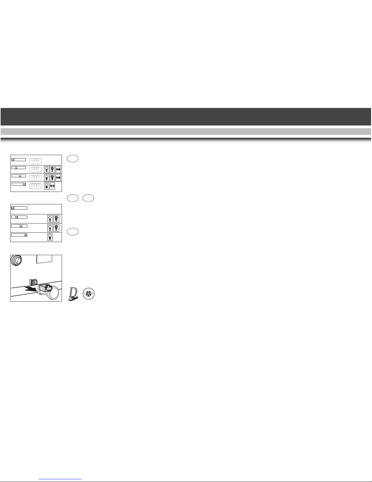
Betriebsarten-Triebwagen
Das Modell hat einen vierstufigen
Betriebsarten-Schalter an
derUnterseite (Abb. 1).
Pos. 0: Stromlos abgestellt
Pos. 1: Beleuchtung eingeschaltet
Abb. 1. Betriebsartenschalter,
Triebwagen
Abb. 2. Betriebsartenschalter,
Beiwagen
Abb. 3. Mehrzwecksteckdose
Fig. 1. Power control switch, Railbus
Fig. 2. Power control switch, Trailer
Fig. 3. Multi-purpose socket
Illustr. 1. Modes d’exploitation,
autorail motorisé
Illustr. 2. Modes d’exploitation,
remorque sans moteur
Illustr. 3. Fiche plate, prise électrique
D
3
GB
USA
F
AAA A
AAA A
AAA A
AAA A
1
AAA A
AAA A
AAA A
AAA A
2
Page 3

5
Pos. 2: Motor und Beleuchtung
eingeschaltet
Pos. 3: Motor und Beleuchtung
eingeschaltet, jedoch
ohne rotes Schlusslicht,
(werkseitige Einstellung
bei Auslieferung)
Betriebsarten-Steuerwagen
Das Modell hat einen vierstufigen Betriebsarten-Schalter an der Unterseite (Abb. 2).
Pos. 0: Stromlos abgestellt
Pos. 1: Innenbeleuchtung einge-
schaltet (werkseitige Einstellung bei
Auslieferung)
Pos. 2: wie Pos. 1
Pos. 3: wie Pos. 1
Stirnlampen
Die Stirnlampen des Triebwagens
wechselt mit der Fahrtrichtung
weiß/rot.
Innenbeleuchtung
Die Innenbeleuchtung brennt in beiden Fahrtrichtungen.
Mehrzweck-Steckdose
Je eine Mehrzweck-Steckdose für
Flachstecker befindet sich an den
Stirnseiten des Triebwagens und des
Steuerwagens (Abb. 3).
Funktion:
Über diese Steckdose können der
Trieb- und der Steuerwagen miteinander verbunden werden. Es können
so z.B. auch LGB-Wagen mit
Beleuch-tung an die Gleisspannung
angeschlossen werden.
Dazu die Abdeckung der Steckdose
mit einem kleinen Schraubenzieher
vorsichtig heraushebeln.
Nicht das äußere rechteckige
Gehäuse herausziehen!
Analogbetrieb
Hinweis:
Das Modell kann unverändert auf
herkömmlichen analogen Anlagen
eingesetzt werden, solange diese
Funktion nicht in den CVEinstellungen geändert wurde.
LGB-Mehrzugsystem-MZS
Das Modell kann unverändert auf
digitalen Anlagen eingesetzt werden.
Bei digitalem Betrieb verfügt der
Triebwagen über eine Lastnachregelung: Das heißt, die Motordrehzahl
(und damit unter normalen Bedingungen die Geschwindigkeit) wird
konstant gehalten, auch wenn sich
die Belastung des Triebwagens
ändert, z. B. in Kurven oder auf
Steigungen.
Hinweis:
Die Lastnachregelung funktioniert
nicht bei bereits maximaler
Belastung/Geschwindigkeit, da dann
keine Spannungsreserve zur
Verfügung steht.
Werkseitige Einstellungen
Hinweis:
Diese sind der CV-Liste zu entnehmen.
Ferngesteuerte Funktionen
Hinweis:
Für diese werden LGB-Handys benötigt.
Funktion:
Durch das Drücken der entsprechenden Taste werden untenstehende
Funktionen ausgelöst.
Funktionstasten:
1 Innenbeleuchtung
Hinweis:
Die Belegung der Funktionstasten
lässt sich auch individuell programmieren4.
Page 4

6
Beleuchtungstaste:
9 Beleuchtung aus/ein
Datenübertragung (seriell)
Bei älteren MZS-Komponenten werden die Befehle als Aneinanderreihung von einzelnen Befehlen gesendet
(z.B. 3 = 1+1+1).
Die meisten MZS-Komponenten lassen sich aber durch ein Upgrade auf
parallele Funktionsauslösung umstellen.
Ausnahmen:
- MZS-Zentrale der 1. Generation
55000 und
- Lokmaus 55010.
Hinweis:
Weitere Informationen erhalten Sie
bei Ihrem Fachhändler.
Datenübertragung (parallel)
Bei den mit "P" gekennzeichneten
MZS-Komponenten werden die
Funktionen dieser Lok parallel ausgelöst, d.h., es entfällt die Pause, die
beim "seriellen" Auslösen entsteht.
Programmierung
Es können zahlreiche Funktionen des
Decoders onboard programmiert
werden, z.B.:
- Beschleunigung
- Bremsverhalten
- Fahrtrichtung
- und vieles mehr
Die Programmierung kann sowohl
über das MZS-PC-Decoderprogrammiermodul 55045 als auch über das
MZS-Universal-Handy 55015 erfolgen.
WARTUNG
Schwierigkeitsgrade der
Wartungsarbeiten:
Einfach
Mittel
Fortgeschritten
Bei unsachgemäßer Wartung erlischt
der Garantieanspruch.
Hinweis:
Um fachgerechte Reparaturleistungen zu erhalten, wenden Sie sich an
Ihren Fachhändler oder an die LGBService-Abteilung (siehe Autorisierter
Service).
Schmierung
- Die Achslager hin und wieder mit je
einem Tropfen LGB-Pflegeöl ölen.
Reinigung
- Sie können das Gehäuse Ihres
Modells mit einem milden
Reinigungsmittel reinigen.
Das Modell nicht in das
Reinigungsmittel eintauchen.
Austauschen der Glühlampen
Lampen (vorne/hinten):
Wir empfehlen, diese Bauteile von
einer autorisierten Werkstatt auswechseln zu lassen. Um fachgerechte
Reparaturleistungen zu erhalten,
wenden Sie sich an Ihren
Fachhändler oder an die LGBService-Abteilung (siehe Autorisierter
Service).
Innenbeleuchtung:
- Mit einem Finger durch eine geöffnete Tür greifen.
- Dach von innen nach oben drücken
und abnehmen.
- Vorsichtig die Lichtplatine von den
Montagesockeln abnehmen.
- Glühlampen austauschen.
- Lichtplatine anbringen.
- Modell wieder zusammmenbauen.
Page 5

7
Ersatzteile1
50019 Pflegeöl
51020 Getriebefett
????? MZS-Decoder onboard
62206 Motor mit Kardankupplung
63120 Stromabnehmerkohlen
mit Hülsen, 8 Stück
(2 Packungen nötig)
68511 Steckglühlampe klar, 5V,
10 Stück
68512 Steckglühlampe rot, 5V,
10 Stück
Index
1 = Ersatzteil
2 = Zubehör
3 = abschaltbar
4 = siehe Anleitung für
Fortgeschrittene
ANLEITUNG FÜR FORTGESCHRITTENE
MZS-Decoder onboard
Um die Funktionen des MZSDecoder onboard individuell zu
ändern, können die Funktionsvariablen
(Confi-guration Variables - CVs) in
den Registern programmiert werden.
Dazu wird benötigt:
- Das MZS-PC-Decoderprogrammiermodul 55045 oder
- Universal-Handy 55015
Hinweis:
Für normalen Betrieb ist es nicht notwendig, die Funktionswerte zu
ändern.
Programmierung
Hinweis:
Beachten Sie die Betriebsanleitungen:
- MZS-PC-Decoderprogrammiermodul
55045 bzw.
- Universal-Handy 55015.
Auslieferungszustand
- Bei Fehlprogrammierungen kann
der Auslieferungszustand der wichtigsten Register des MZS-Decoders
onboard wieder hergestellt werden!
- Hierzu den Funktionswert 55 in
Register CV 55 eingeben.
Dabei wird auch die Lokadresse wieder auf den werkseitigen Wert = 3
programmiert.
Programmieren mit Handy 55015
Vorgehensweise:
- Programmiermodus wählen
- Eingabe > “P”
- Anzeige = “P --”
- Eingabe > 6 - 5 - 5 und rechte
Pfeiltaste
- Anzeige = “P --”
- Eingabe > 5 - 5 - 5 und rechte
Pfeiltaste
Hinweis:
Auslieferungszustand ist wieder hergestellt.
Page 6

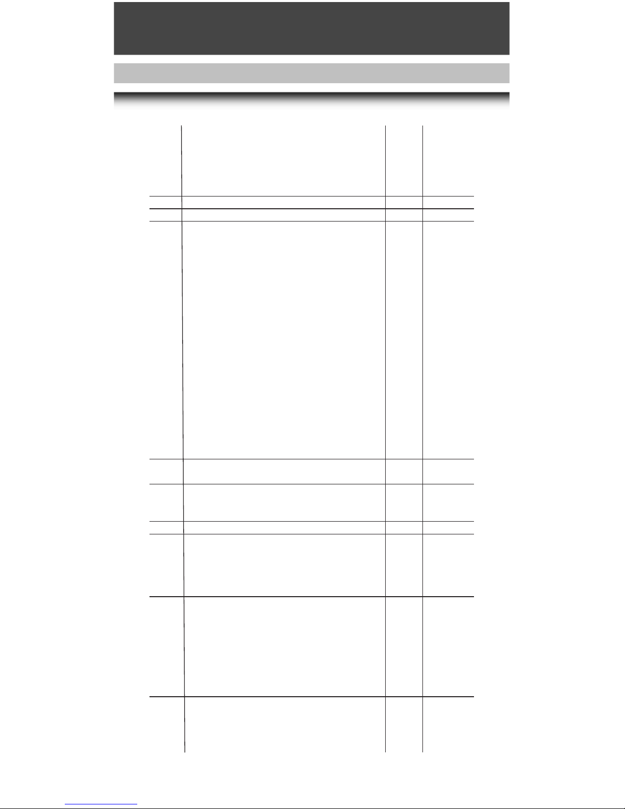
Folgende CVs können programmiert werden:
Register Belegung Bereich Werkseitige
Einstellung
CV1 Lokadresse
Mit LGB-Mehrzugsystem (00-22) [3]
CV2 Anfahrspannung
Spannungswert bei Fahrstufe 1 - falls Lok erst in höherer
Fahrstufe anfährt, Wert erhöhen. (0-255) [2]
CV3 Beschleunigung
1 = schnelle Beschleunigung, 255 = langsame B. (1-255) [3]
CV4 Verzögerung
1 = schnelles Bremsen, 255 = langsames Bremsen (1-255) [3]
CV5 Maximale Fahrspannung
Spannungswert für höchste Fahrstufe - wenn geringere
Höchstgeschwindigkeit gewünscht wird, Wert verringern. (1-255) [255]
CV5 nach Eingabe von CV6 (beim Programmieren mit älteren
55015) Funktionswert im zu programmierenden Register
CV6 CV-Nr. des zu programmierendes Register (beim
Programmieren mit älteren 55015)
CV29 NMRA-Konfiguration
Bit-Programmierung
Bit 1: Fahrtrichtung, 0 = normal, 1 = invers [0]
Bit 2: Fahrstufen, 0 = 14 (LGB), 2 = 28 [0]
Bit 3: Analogbetrieb, 0 = gesperrt, 4 = möglich [4]
Bit 4: nicht besetzt [0]
Bit 5: Fahrstufentabelle, 0 = werkseitig programmiert,
16 = vom Anwender programmiert [0]
Bit 6: Adressbereich, 0 = 0-127 (LGB), 32 = 128-10039 [0]
Zum Programmieren die Werte für die einzelnen Bits addieren
und das Ergebnis als Funktionswert programmieren.
Hinweis: Um eine Lok auf inverse Fahrtrichtung zu programmieren (z. B. F7 A-B-A-Kombination), Funktionswert 5
programmieren. Achtung! Lokadressen 128-10039 und 28
Fahrstufen sind nicht mit dem LGB-MZS verwendbar. [4]
CV49 Spannungswert für Funktionsausgang F1
(Lokspezifisch, nicht verändern, da sonst Funktionen
beeinträchtigt oder zerstört werden können) (1-32) [5]
CV50 Spannungswert für Lichtausgänge (siehe CV49) (1-32) [5]
CV51 Schalttaste für Funktionsausgang F1
0 = Lichttaste 9
1 = Taste 1 (Tasten 2-8 nicht belegt)
9 = Taste 1 (Tasten 2-8 ebenfalls belegt)
10 = Taste 2
11 = Taste 3
12 = Taste 4
13 = Taste 5
14 = Taste 6
15 = Taste 7
16 = Taste 8
8
Page 7
9
64 = Lichttaste 9 (ein nur bei Rückwärtsfahrt)
65 = Taste 1 (ein nur bei Rückwärtsfahrt)
128 = Lichttaste 9 (ein nur bei Vorwärtsfahrt)
129 = Taste 1 (ein nur bei Vorwärtsfahrt)
(Lokspezifisch, nicht verändern, da sonst Funktionen
beeinträchtigt oder zerstört werden können) [1]
CV52 Schalttaste Licht vorne (siehe CV51) [128]
CV53 Schalttaste Licht hinten (siehe CV51) [64]
CV54 LGB-Konfiguration [2]
Bit-Programmierung
Bit 1: Übernahme-Funktion, 0 = aus, 1 = ein [0]
Bit 2: Lastnachregelung mit MZS, 0 = aus, 2 = ein [2]
Bit 3: Lastnachregelung ananlog, 0 = aus, 4 = ein [0]
Bit 4: ohne Funktion
Bit 5: 0 = F1 konstant, 16 = F1 blinkend [0]
Bit 6: 0 = F2 konstant, 32 = F2 blinkend [0]
Bit 7: 0 = Zwei Auspuffschläge/Radumdrehung,
64 = Vier Auspuffschläge [0]
Bit 8: Automatisches Bremsgeräusch, 0 = ein, 128 = aus [0]
Zum Programmieren die Werte für die einzelnen Bits addieren
und das Ergebnis als Funktionswert programmieren.
Die Werte für Bit 5-8 variieren von Lok zu Lok. Die Werte für
Ihre Lok können über das MZS-PC-Decoderprogrammiermodul 55045 ausgelesen werden.
Übernahme-Funktion ein: Beim Betrieb mit 55015 kann
nach Anwählen der Lok die Reglerstellung 2 Sekunden lang
nachgeregelt werden, ohne dass die Lok anhält
CV55 Wiederherstellen des Auslieferungszustands
Programmierung: 6-55-> 5-55->
CV56 Spannungswert für Funktionsausgang F2
(Lokspezifisch, nicht verändern, da sonst Funktionen
beeinträchtigt oder zerstört werden können) (1-32) [32]
CV57 Schalttaste für Funktionsausgang F2 (siehe CV51) [10]
CV58 Pausen-Pendelzeit (Analogbetrieb) (0,5 Sekunden x Wert)
(0-255) [0]
Wenn die analoge Fahrspannung umgepolt wird, wartet die
Lok entsprechend der eingestellten Zeit, bevor sie in der
neuen Fahrtrichtung anfährt (0-255) [0]
CV60 Lastnachregelung: Maximaler Nachregelfaktor
Legt maximale Erhöhung oder Verringerung des
Spannungswerts fest, der pro Zeiteinheit (aus CV61) nach-
geregelt wird.
1 = kleine Nachregelungsschritte,
255 = große Nachregelungsschritte
Werkseitige Programmierung ist optimal an LGB-Motoren
angepasst. (1-255) [10]
CV61 Lastnachregelung: Nachregelgeschwindigkeit
Legt fest, wie oft pro Sekunde nachgeregelt wird - ob
die Lok auf Kurven und Steigungen sofort oder träge reagiert
Page 8

10
0 = schnelle Nachregelung, 255 = sehr langsame
Nachregelung (0-255) [5]
CV62 Lastnachregelung: Nachregelstärke
Begrenzt die Nachregelung auf eine maximale Abweichung
vom Sollwert. Bei besonders großen Belastungen des Motors
wird nur bis zu diesem Differenzwert nachgeregelt - für
realistischeren Betrieb, damit Loks z. B. bei Bergfahrt nicht
voll nachregeln.
0 = keine Nachregelung, 255 = maximale Nachregelung (0-255) [255]
CV67
bis
CV94 Fahrstufentabelle vom Anwender programmiert (siehe CV 29)
Die Geschwindigkeitstabelle wird immer mit 28 Werten ab-
gelegt, die in CV 67 bis CV 94 programmiert werden.
Beim Betrieb mit dem LGB-MZS wird jeder zweite Wert über-
sprungen (14 Fahrstufen).
Werkseitig programmierte Fahrstufentabelle:
7, 9, 11, 13, 16, 20, 24, 28, 32, 36, 42, 48, 54, 60, 68, 76,
84, 92, 102, 112, 124, 136, 152, 168, 188, 208, 230, 255
Vorgeladene Werte der programmierbaren Kurve:
8, 16, 24, 32, 40, 48, 56, 64, 72, 80, 88, 96, 104, 112, 120,
128, 136, 144, 152, 160, 168, 176, 184, 192, 208, 224, 240, 255
Hinweis:
Fahrstufentabelle ist werkseitig programmiert und
braucht nicht verändert zu werden.
Zum Programmieren ist das MZS-PC-Decoderprogrammiermodul 55045 empfehlenswert.
Beispiel zur Bit-Programmierung:
CV 29: Die Lok soll mit inverser Fahrtrichtung mit vom
Anwender programmierter Fahrstufentabelle fahren,
Analogbetrieb soll möglich sein:
Bit 1 = 1, Bit 2 = 0, Bit 3 = 4, Bit 4 = 0, Bit 5 = 16,
Bit 6 = 0. 1+4+16=21.
Also CV 29 auf Funktionswert 21 programmieren.
Page 9

AUTORISIERTER SERVICE
Bei unsachgemäßer Wartung wird
Ihre Garantie ungültig. Um fachgerechte Reparaturleistungen zu erhalten, wenden Sie sich an Ihren
Fachhändler oder an die LGBService-Abteilung:
Gebr. Märklin & Cie. GmbH
LGB Service-Abteilung
Witschelstraße 104
90431 Nürnberg
Deutschland
Telefon: (0911) 83707-38
Telefax: (0911) 83707 818
Die Einsendung erfolgt zu Ihren
Lasten.
VORSICHT! Dieses Modell ist nicht
für Kinder unter 8 Jahren geeignet.
Das Modell hat kleine, scharfe und
bewegliche Teile. Verpackung und
Bedienungs-anleitung aufbewahren.
Artikel, technische Daten und
Lieferdaten können sich ohne Vor ankündigung ändern. Einige Artikel
sind nicht überall und über alle
Fachhändler erhältlich. Einige
Abbildungen zeigen Handmuster.
LGB und Märklin sind einge-tragene
Marken der Firma Gebr. Märklin &
Cie. GmbH, Göppingen. Andere
Marken sind ebenfalls geschützt.
© Gebr. Märklin & Cie. GmbH
GmbH
11
Page 10

DR Rail Car + Control Cab Car
VT 133
Item No. 29650
THE PROTOTYPE
Many passenger routes are too lightly traveled to support a locomotivepowered passenger train. For these
routes, a railbus often is the best
solution - a passenger coach with its
own motor.
Many railbuses are used together
with a control cab car to increase
capacity. On some lines, one or two
freight cars were added to make a
short mixed train.
THE MODEL
General
This model is part of the LGB range
of more than 600 high-quality products. The product range includes:
locomotives, trains, track system
and accessories in size G as well as
the LGB multi-train system MTS.
For more information on the complete LGB product range, please refer
to the comprehensive LGB catalog.
Safety note
All safety notes given in these operating instructions must be observed!
Design
- Weatherproof model as detailed
replica
- Luxuriously equipped
Equipment
- Power pickups on control
cab car 4
- Powered wheels 4
- Multi-purpose socket
Rail car 2
Control cab car 1
- Encapsulated gearbox with
seven-pole Bühler engines3 1
- Rail car - front lights, 4
for light variation white/red
(in direction of travel3
respectively 2)
- Rail car, lamps for
interior lighting 3
- Control cab car, lamps for
interior lighting 3
- Factory-installed onboard MTS
decoder for analog and digital
operation.
- Length ca. 725 mm (21.7in)
- Weigth ca. 3,125 g (11lb)
- Voltage limitation system (5V)
- Operating mode selector, four-way
Rail car 1
Control cab car 1
- The following vehicle parts can be
opened:
- Doors
Scope of delivery (accessories)
- Operating instructions 1
- Power cable for
multi-purpose sockets 1
Prior to start-up
During extended operation, this
model may leave carbon dust or
other debris around the track. This
dust and debris can stain carpet and
other materials. Consider this when
setting up the track.
Note:
LBG shall not be liable in case of
damages.
Power supply
For safety and reliability, operate this
model with LGB transformer only
(min. driving current 1 A). The use of
non-LGB transformers will void your
warranty.
12
GB
USA
Page 11

Note:
For more information on LGB transformers, power packs and controls
for indoor, outdoor and multi-train
operation, see the LGB catalog.
Operation
Do not connect this model to other
loco models with different starting
characteristics. This can damage the
internal gearing.
Power cable for multi-purpose sockets
Prior to start-up connect rail car and
control cab car by means of the
enclosed power cable (see multi-purpose socket)
Operating modes - rail car
This model has a four-way operating
mode selector mounted on the bottom (Fig. 1).
Pos. 0: All power off
Pos. 1: Power to lights
Pos. 2: Power to motor and
lights
Pos. 3: Power to motor and
lights, however, not to
red rear end light (factory
pre-set)
Operating modes - control cab car
This model has a four-way operating
mode selector mounted on the bottom (Fig. 2).
Pos. 0: All power off
Pos. 1: Interior lighting on (fac-
tory pre-set)
Pos. 2: see Pos. 1
Pos. 3: see Pos. 1
Front lights
The head lights of the rail car change
red/white according to the direction
of travel.
Interior lighting:
The interior lighting is on in each
direction of travel.
Multi-purpose socket
One each multi-purpose socket, suitable for flat connectors, on the front
walls of the rail car and the control
cab car (Fig. 3).
Function:
The rail car and the control cab car
can be connected by means of this
socket. This way, for example, also
LGB coaches with lighting can be
provided with track power.
For this purpose, gently remove the
cover of the socket using a small
straight screwdriver to pry it out.
Do not pull out the rectangular outer
housing.
Analog mode
Note:
This model can also be operated on
traditional analog systems without
making any alterations, provided that
this function has not been changed
in the CV settings.
LGB Multi-Train System MTS
This model can also be operated on
digital systems without making any
alterations.
In digital mode, the rail car has a load
readjustment function, which means
that the motor speed is kept constant
(and under normal conditions the
loco speed), even when the load of
the rail car changes, for example, in
curves or on grades.
Note:
This feature does not work at maximum load/speed, because in that
case there would be no voltage
reserve.
Factory settings
Note:
Please refer to the CV list.
Remote-controlled functions
Note:
13
Page 12

14
LGB remote control units are
required for the following functions.
Function:
Pressing the appropriate key triggers
the functions listed below.
Function keys:
1 Interior lighting
Note:
Function key assignment can be customized.4
Lighting key:
9 Lighting off/on
Data transmission (serial)
With older MTS components, commands are transmitted as a sequence
of single commands (e.g. 3 =
1+1+1).
However, most MTS components
can be upgraded to parallel function
commands.
Exceptions:
- First generation 55000 MTS
Central Station and
- 55010 Train Mouse.
Note:
Further information can be obtained
from your authorized retailer.
Data transmission (parallel)
When using MTS components
marked with a "P", the loco can
receive "parallel" function commands, which eliminate the pause
that occurs when a "serial" command
is received.
Programming
Numerous functions of the onboard
decoders can be configured, e.g.
- Acceleration
- braking response
- direction of travel
- and many more.4
The decoder can either be configured
using the 55045 MTS-PC
Programming Module or the 55015
MTS Universal Remote Control
Unit.4
SERVICE
Do-it-yourself service levels
Beginner
Intermediate
Advanced
Improper service will void your warranty.
Note:
For quality service, contact your
authorized retailer or an LGB factory
service station (see Authorized
Service).
Lubrication
- Lubricate the axle bearings with a
drop of LGB-oil every now and
then.
Cleaning
- This model can be cleaned externally using a mild detergent and
gentle stream of water.
Do not immerse this model in the
detergent.
Replacing the light bulbs
Lights (front/rear):
We recommend to have these components exchanged by an authorized
repair shop. For quality service, contact your authorized retailer or an
LGB factory service station (see
Authorized Service).
Page 13

Interior lighting:
- Reach inside through an open
door using a finger.
- Push roof upward from inside and
remove.
- Carefully remove light board from
support.
- Exchange light bulbs.
- Install light board.
- Reassemble.
Spare parts1
50019 Maintenance Oil
51020 Gear Lubricant
????? MTS Onboard Decoder
62206 Motor with cardab shaft
63120 Brushes with bushings, 8
pieces
(2 packages needed)
68511 Plug-In Bulb, Clear, 5V,
10 pieces
68512 Plug-In Bulb, Red, 5V,
10 pieces
Index
1 = Spare part
2 = Accessories
3 = Switch-off option
4 = See Instructions for Advanced
Users
INSTRUCTIONS FOR ADVANCED
USERS
MTS Onboard Decoder
To change the functions of the MTS
Onboard Decoder as desired, configuration Variables - CVs) can be programmed in the registers.
This option requires the following
equipment:
- 55045 MTS PC Decoder
Programming Module or
- 55015 Universal Remote Control Unit
Note:
For normal operation, it is not necessary to change any function values.
Programming
Note:
Please consult the operating instructions for the
- 55045 MTS PC Decoder
Programming Module or
- 55015 Universal Remote Control
Unit
Original factory settings
- If programming results in unsatisfactory operation, the original factory settings of the MTS Onboard
Decoder can be recovered for the
most important registers!
- To do this, enter function value 55
in register CV 55.
This also reprograms the loco
address to the factory-set value = 3.
Configuration using a 55015 Remote
Control Unit
Procedure:
- Select programming mode
- Enter > “P”
- Display shows "P --"
- Enter > 6 - 5 - 5 and press right
arrow key
- Display shows "P --"
- Enter > 5 - 5 - 5 and press right
arrow key
Note:
The original factory settings have
now been recovered.
15
Page 14

The following registers can be configured:
Register Function Available Factory
values pre-setting
CV1 Loco address With LGB Multi-Train System (00-22) [3]
CV2 Starting voltage
Voltage for speed setting 1 - if loco only starts at a higher
speed setting, increase value. (0-255) [2]
CV3 Acceleration
Acceleration (1 = fast, 255 = slow) (1-255) [3]
CV4 Braking
1 = fast, 255 = slow (1-255) [3]
CV5 Maximum track voltage
Voltage for highest speed step - if a lower top speed is
desired, decrease value. (1-255) [255]
CV5 Function value for CV to be programmed after input of CV6
(when programming with older 55015)
CV6 CV to be programmed (when programming with older 55015)
CV29 NMRA configuration
Bit configuration
Bit 1: direction of travel, 0 = normal, 1 = reversed [0]
Bit 2: speed steps, 0 = 14 (LGB), 2 = 28 [0]
Bit 3: analog operation, 0 = not possible, 4 = possible [4]
Bit 4: not assigned [0]
Bit 5: speed steps table, 0 = factory-programmed,
16 = user-programmed [0]
Bit 6: address area, 0 = 0-127 (LGB), 32 = 128-10039 [0]
To program, add the values for the individual bits and program
the resulting function value. Note: To program a loco to
reversed direction of travel (e.g. F7 A-B-A combination),
program function value 5.
Attention! Loco addresses 128-10039 and 28 speed steps
cannot be used with LGB MTS. [4]
CV49 Voltage for function terminal F1
(depends on loco model, do not change, as functions can
be affected or destroyed) (1-32) [5]
CV50 Voltage for lighting terminals (see CV49) (1-32) [5]
CV51 Command key for function terminal F1
0 = lighting button 9
1 = button 1 (buttons 2-8 not assigned)
9 = button 1 (buttons 2-8 also assigned)
10 = button 2
11 = button 3
12 = button 4
13 = button 5
14 = button 6
15 = button 7
16 = button 8
64 = lighting button 9 (ON only when loco is reversing)
65 = button 1 (ON only when loco is reversing)
16
Page 15

128 = lighting button 9 (ON only when loco is moving forward)
129 = button 1 (ON only when loco is moving forward)
(Depends on loco model, do not change, as functions
can be affected or destroyed) [1]
CV52 Command key for front lighting terminal (see CV51) [128]
CV53 Command key for rear lighting terminal (see CV51) [64]
CV54 LGB configuration [2]
Bit configuration
Bit 1: hand-off function, 0 = off, 1 = on [0]
Bit 2: MTS Back-EMF, 0 = off, 2 = on [2]
Bit 3: analog Back-EMF, 0 = off, 4 = on [0]
Bit 4: no function
Bit 5: 0 = F1 constant, 16 = F1 flashing [0]
Bit 6: 0 = F2 constant, 32 = F2 flashing [0]
Bit 7: 0 = two chuffs/revolution,
64 = four chuffs [0]
Bit 8: automatic brake sounds, 0 = on, 128 = off [0]
To program, add the values for the individual bits and
program the resulting function value. The values for Bits 5-8
vary between locos. The values for your loco can be read
using the 55045 MTS PC Decoder Programming Module.
Hand-off function ON: When operating with 55015, you can
adjust direction and speed for two seconds after selecting
a loco in motion without causing the loco to stop. [2]
CV55 Recover factory-set values of the CV configuration:
6-55-> 5-55->
CV56 Voltage for function terminal F2
(depends on loco model, do not change, as functions can
be affected or destroyed (1-32) [32]
CV57 Command key for function terminal F2 (see CV51) [10]
CV58 Pause time (analog operation) (0.5 seconds x function value)
(0-255) [0] When the polarity of the analog track voltage is
reversed, the loco waits for the programmed time period,
then accelerates in the new direction. (0-255) [0]
CV60 Back-EMF: max. adjustment factor Specifies the maximum
increase or decrease of voltage applied during each time
interval (programmed in CV61)
1 = small adjustment steps,
255 = large adjustment steps
The factory-set values are optimized for LGB motors. (1-255) [10]
CV61 Back-EMF: adjustment frequency Specifies how often per
second the motor voltage is adjusted - accordingly, the loco
will react to curves and grades immediately or with a short
delay 0 = immediate adjustment, 255 = maximum delay (0-255) [5]
CV62 Back-EMF: max. adjustment
Limits the total adjustment in motor voltage to a maximum
deviation from setpoint. If there is a very large load on the
motor, the adjustment will not exceed this value - for more
realistic operations, so that locos will slow a bit on grades.
0 = no adjustment, 255 = maximum adjustment (0-255) [255]
17
Page 16

CV67
to
CV94 Speed steps table, user-programmable (see CV 29): The
speed table is always saved with 28 speed steps to be pro-
grammed in CV67 to CV94.
With LGB MTS, every second value is skipped (14 speed
steps). Factory-set speed steps:
7, 9, 11, 13, 16, 20, 24, 28, 32, 36, 42, 48, 54, 60, 68, 76, 84,
92, 102, 112, 124, 136, 152, 168, 188, 208, 230, 255
Pre-set values for user-programmable speed steps:
8, 16, 24, 32, 40, 48, 56, 64, 72, 80, 88, 96, 104, 112, 120,
128, 136, 144, 152, 160, 168, 176, 184, 192, 208, 224, 240,
255
Note:
The speed steps are factory-set and needn't be changed.
We recommend the 55045 MTS PC Decoder Programming
Module for programming.
Example for bit programming:
CV 29: A loco shall run in reverse direction with user-
programmed speed steps, analog operation shall be possible:
Bit 1 = 1, Bit 2 = 0, Bit 3 = 4, Bit 4 = 0, Bit 5 = 16,
Bit 6 = 0. 1+4+16=21.
Thus, program CV 29 to function value 21. (0-255)
18
Page 17

AUTHORIZED SERVICE
Improper service will void your warranty. For quality service, contact
your authorized retailer or one of the
following LGB factory service stations:
Gebr. Märklin & Cie. GmbH
LGB Service-Department
Witschelstrasse 104
90431 Nürnberg
Deutschland
Telephone: (0911) 83707-38
Telefax: (0911) 83707 818
You are responsible for any shipping
costs, insurance and customs fees.
CAUTION! This model is not suitable
for children under 8 years of age.
This model has small parts, sharp
parts and moving parts. Retain the
packing and the operating manual.
Products, specifications and availability dates are subject to change
without notice. Some products are
not available in all markets and at all
retailers. Some products shown are
pre-production prototypes. LGB and
Märklin are registered trademarks of
Gebr. Märklin & Cie. GmbH,
Göppingen. Other trademarks are
also the property of their owners.
© Gebr. Märklin & Cie. GmbH
19
Page 18

Automotrice & Voiture-pilote DR
VT 133
N° art. 29650
LE PROTOTYPE
Généralités
Ce reproduction fidèle intègre le programme LGB qui compte au total
plus de 600 produits d'une qualité
exceptionnelle. La gamme de produits se décline en matériels roulants, réseaux et accessoires à
l´échelle "G", sans oublier le système
multitrain SMT de LGB.
Pour de plus amples informations,
nous vous invitons à consulter le
catalogue LGB qui réunit l'intégralité
de notre programme.
Consignes de sécurité
Les consignes de sécurité rappelées
dans les instructions de service sont
à observer !
Modèle
- Fidèle reproduction résistante aux
intempéries.
- Equipement très complet.
Équipement
- Capteurs de courant de
l'automotrice 4
- Roues motrices 2
- Douille à usages multiples
Automotrice 2
Voiture-pilote 1
- Boîte de vitesse cuirassée, avec
motors Bühler à sept pôles3 1
- Automotrice - Feux avant, 4
pour commutation éclairage
blanc/rouge
(dans le sens de la marche3 respectivement 2)
- Automotrice, ampoules pour
éclairage intérieur 3
- Voiture-pilote, ampoules pour
éclairage intérieur 3
- Décodeur SMT multitrain embarqué
pour fonctionnement analogique et
numérique.
- Longueur env. 725 mm
- Poids env. 3 125 g
- Circuit de stabilisation de tension
(5V)
- Sélecteur de modes opératoires, à
quatre positions
Automotrice 1
Voiture-pilote 1
- Ouvrants:
- Portes
Equipement (accessoires)
- Instructions de service 1
- Câble électrique pour
Douilles à usages multiples 1
Avant la mise en service
L'utilisation peut générer à la longue
une abrasion au niveau des pièces
mécaniques, des poussières et
débris se déposent alors sur les
moquettes et autres matériaux. Il
convient d'en tenir compte lors de
l'installation du réseau.
Nota:
LGB décline toute responsabilité en
cas de dommages.
Bloc d'alimentation
Pour des raisons de sécurité et de
fiabilité, utiliser exclusivement un
bloc d'alimentation LGB (de sortie
supérieure à 1 A) pour faire fonctionner votre locomotive. Aucune garantie ne sera accordée si un bloc d'alimentation autre est installé.
Nota:
Pour un complément d'informations
sur les blocs d'alimentation LGB et
régulateurs à utiliser en intérieur ou
en extérieur ainsi que sur le système
F
20
Page 19

multitrain, nous vous invitons à
consulter le catalogue LGB.
Service
Pour éviter d'endommager le train
d'engrenages, ne pas accoupler cette
locomotive à d'autres modèles de
locomotive présentant des caractéristiques de démarrage différentes.
Câble électrique pour douilles à usages multiples
Raccorder l'automotrice et la voiturepilote à l'aide du câble électrique
fourni (voir douille à usages multiples)
Modes opératoires - Automotrice
Ce modèle est équipé d'un sélecteur
d'alimentation à quatre positions
situé en dessous (ill. 1).
Pos. 0: Alimentation coupée
Pos. 1: Alimentation de l'éclairage
Pos. 2: Alimentation du moteur
et de l'éclairage
Pos. 3: Alimentation du moteur
et de l'éclairage, néanmoins sans feu rouge à
l'arrière, (réglage effectué
en usine)
Modes opératoires - Voiture-pilote
Ce modèle est équipé d'un sélecteur
d'alimentation à quatre positions
situé en dessous (ill. 2).
Pos. 0: Alimentation coupée
Pos. 1: Alimentation de l'éclairage
intérieur (réglage effectué
en usine)
Pos. 2: identique à pos. 1
Pos. 3: identique à pos. 1
Feux avant
Commutation blanc/rouge des feux
avant selon le sens de la marche.
Éclairage intérieur
L'éclairage intérieur est alimenté
dans les deux sens de marche.
Douille à usages multiples
Un bloc multiprise pour fiche "plate"
est placé respectivement sur les parties avant de l'automotrice et de la
voiture-pilote (ill. 3).
Fonction :
La douille permet de raccorder l'automotrice à la voiture-pilote. D'autres
voitures LGB, par exemple, peuvent
elles aussi bénéficier de la tension
fournie par la voie.
Utiliser un petit tournevis pour soulever, avec précaution, le couvercle de
la douille.
Ne pas retirer la protection rectangulaire extérieure !
Fontionnement analogique
Nota:
Le modèle réduit peut fonctionner
sur un réseau analogique conventionnel sans qu'aucune modification
ne soit nécessaire, tant que le paramétrage de cette fonction n´a pas été
modifié au niveau des registres CV.
Le système SMT multitrain de LGB
Le modèle réduit peut être utilisé sur
un réseau numérique sans qu'aucune modification ne soit nécessaire.
La locomotive utilisée en fonctionnement numérique dispose d'une fonction de force contre-électromotrice
(FCEM) : le régime moteur (et par
conséquent la vitesse de la locomotive en conditions normales) est constant, même lorsque la charge de la
locomotive varie, comme par exemple dans un virage ou une montée.
Nota:
La fonction de force contre-électromotrice est désactivée en cas de
charge/vitesse maximale, aucune
réserve de tension n'étant alors
disponible.
21
Page 20

Paramétrages à la livraison
Nota:
Veuillez vous reporter à la liste des
registres.
Fonctions télécommandées
Nota:
Une télécommande LGB est nécessaire.
Fonction :
En appuyant sur le bouton correspondant, il est possible d'activer
les fonctions suivantes :
Boutons de fonction :
1Éclairage intérieur
Nota:
L'utilisateur a la possibilité de personnaliser les fonctions assignées
aux boutons de fonction4.
Bouton éclairage:
9Marche/arrêt de l'éclairage
Transfert des données (mode sériel)
Sur les systèmes SMT intégrant
d'anciens composants, les données
sont transmises sous formes de bits
individuels juxtaposés (par ex. 3 =
1+1+1).
Une mise à niveau, possible pour la plupart des composants SMT, permet
toutefois un transfert en mode parallèle.
Exceptions:
- L'unité centrale SMT 55000 de la
1ère génération
- La souris SMT 55010.
Nota:
Pour de plus amples informations,
veuillez contacter votre revendeur.
Transfert des données (mode parallèle)
Si l'équipement intègre des composants SMT marqués d'un "P", les
fonctions de la locomotive sont commandées en mode parallèle, la pause
inhérente à l'envoi en mode sériel est
supprimée.
Programmation
De nombreuses autres fonctions du
décodeur embarqué sont programmables, quelques exemples :
- Accélération
- Freinage
- Sens de la marche
- Nombreuses autres fonctions4
La programmation est possible via le
module de programmation OP 55045
du décodeur SMT ou via la télécommande universelle SMT 550154.
ENTRETIEN
Niveaux d´entretien :
Débutant
Intermédiaire
Expert
Un entretien inapproprié du produit
exclut tout droit à la garantie.
Nota:
Pour une réparation adéquate, adressez-vous à votre revendeur ou à un
centre d'entretien LGB autorisé (voir
Centres d'entretien autorisés).
Lubrification
- Les coussinets d'essieu sont à
graisser par intervalles, quelques
gouttes d'huile d'entretien LGB suffisent.
Nettoyage
- Utiliser un produit non agressif
pour nettoyer la caisse.
Ne pas immerger la locomotive dans
la solution utilisée pour le nettoyage.
Remplacement des ampoules
Ampoules (avant/arrière):
Il est conseillé de confier l'échange
de ces pièces à un service autorisé.
22
Page 21

Veuillez entrer en contact avec votre
revendeur ou avec un Centre d'entretien LGB (voir Centres d'entretien
autorisés).
Éclairage intérieur:
- Introduire un doigt par la porte.
- Exercer de l'intérieur une légère
pression contre le toit et déposer
celui-ci.
- Retirer avec précaution la platine de
son socle.
- Echanger l'ampoule.
- Remettre en place la platine.
- Procéder au réassemblage.
Pièces de rechange1
50019 Huile d'entretien
51020 Pâte lubrifiante
????? Décodeur SMT embarqué
62206 Moteur avec accouple-
ment à cardan
63120 Capteurs de courant avec
cosses, 8 unités
(2 conditionnements sont
nécessaires)
68511 Ampoule enfichable claire,
5V, 10 unités
68512 Ampoule enfichable claire,
5V, 10 unités
Définition des renvois en exposant
1 = Pièce de rechange
2 = Accessoires
3 = Déconnectable
4 = cf. instructions de service à l'a-
dresse des experts
INSTRUCTIONS A L'ADRESSE DES
EXPERTS
Décodeur SMT embarqué
La modification individuelle des
fonctions du décodeur SMT embarqué est possible, il suffit pour cela de
programmer les variables de fonction
dans les registres (Configuration variables - CV) correspondants.
Equipement nécessaire :
- Le module de programmation OP
55045 du décodeur SMT ou
- la télécommande universelle 55015
Nota:
La modification des valeurs de fonction n'est pas nécessaire en fonctionnement normal.
Programmation
Nota:
Lire attentivement et observer les
instructions de service :
- du module de programmation OP
55045 du décodeur SMT ou
- de la télécommande universelle 55015.
Rétablissement du paramétrage
usine
- Il est possible de rétablir le paramétrage initial des principaux registres
du décodeur embarqué SMT en cas
de programmation erronée !
- Saisir la valeur de fonction 55 dans
le registre CV 55.
La programmation à l'adresse de
locomotive est elle aussi rétablie à la
valeur paramétrée en usine = 3.
Programmation à l'aide de la télécommande 55015
Procédure :
- Sélectionner le mode de programmation
- Saisie > “P”
- Affichage = "P --"
- Saisie > 6 - 5 - 5 et flèche droite du
curseur
- Affichage = "P --"
- Saisie > 5 - 5 - 5 et flèche droite du
curseur
Nota:
La programmation usine est rétablie.
23
Page 22

Vous pouvez programmer les registres suivants :
Registre Fonction Valeurs Valeur
disponibles usine
CV1 Adresse de la locomotive
Avec système multitrain (SMT) LGB (00-22) [3]
CV2 Tension au démarrage. Tension pour réglage de vitesse 1.
Si le réglage de la vitesse au démarrage de la locomotive est
plus élevé, augmenter la valeur. (0-255) [2]
CV3 Accélération
1= accélération rapide, 255 = accélération lent (1-255) [3]
CV4 Freinage
1 = freinage rapide, 255 = freinage lent (1-255) [3]
CV5 Tension maximale
Tension pour réglage de vitesse maximal. Diminuer la valeur,
si une vitesse maximale moins élevée est désirée. (1-255) [255]
CV5 Après entrée dans CV6 (programmation avec ancienne
55015), valeur de fonction dans le registre à programmer.
CV6 Registre à programmer (Programmation avec ancienne 55015)
CV29 Configuration NMRA
Programmation au niveau du bit
Bit 1: sens de la marche, 0 = marche avant, 1 = marche
arrière [0]
Bit 2: réglages de vitesse, 0 = 14 (LGB), 2 = 28 [0]
Bit 3: fonctionnement analogique, 0 = impossible, 4 = possible
[4]Bit 4: non utilisé [0]
Bit 5: réglages de vitesse, 0 = programmés en usine,
16 = programmation par l'utilisateur [0]
Bit 6: bloc d'adresses, 0 = 0-127 (LGB), 32 = 128-10039 [0]
Pour programmer, ajouter les valeurs pour les bits individuels
et programmer la valeur de fonction résultante.
Conseil: pour programmer l'inversion du sens de la marche
d'une locomotive (p. ex. configuration F7 A-B-A), programmer
la valeur de fonction 5.
Attention! Les adresses de la locomotive 128-10039 et
les 28 réglages de vitesses ne peuvent pas être utilisés avec
le SMT LGB. [4]
CV49 Tension pour la borne de fonction F1
(spécifique au modèle de locomotive, ne pas modifier,
les fonctions pouvant être affectées, voire rendues inopérantes) (1-32) [5]
CV50 Tension pour les bornes d'éclairage (voir CV49) (1-32) [5]
CV51 Commande pour la borne de fonction F1
0 = bouton d'éclairage 9
1 = bouton 1 (boutons 2-8 non utilisés)
9 = bouton 1 (boutons 2-8 également utilisés)
10 = bouton 2
11 = bouton 3
12 = bouton 4
13 = bouton 5
14 = bouton 6
24
Page 23

15 = bouton 7
16 = bouton 8
64 = bouton d'éclairage 9 (en service uniquement lorsque
la locomotive se déplace en marche arrière)
65 = bouton 1 (en service uniquement lorsque la locomotive
se déplace en marche arrière)
128 = bouton d'éclairage 9 (en service uniquement lorsque
la locomotive se déplace en marche avant)
129 = bouton 1 (en service uniquement lorsque la locomotive
se déplace en marche avant)
(spécifique au modèle de locomotive, ne pas modifier, les
fonctions pouvant être affectées, voire rendues totalement
inopérantes) [1]
CV52 Commande pour la borne d'éclairage avant (voir CV51) [128]
CV53 Commande pour la borne d'éclairage arrière (voir CV51) [64]
CV54 Configuration LGB [2]
Programmation au niveau du bit
Bit 1: fonction transfert de contrôle, 0 = hors service,
1 = en service [0]
Bit 2: fonction FCEM du SMT, 0 = hors service,
2 = en service [2]
Bit 3: fonction FCEM analogique, 0 = hors service,
4 = en service [0]
Bit 4: aucune fonction
Bit 5: 0 = F1 continu, 16 = F1 clignotant [0]
Bit 6: 0 = F2 continu, 32 = F2 clignotant [0]
Bit 7: 0 = deux bouffées de fumée/ rotation de roue,
64 = quatre bouffées de fumée [0]
Bit 8: bruit du freinage automatique, 0 = en service,
128 = hors service [0]
Pour programmer, ajouter les valeurs pour les bits
individuels et programmer la valeur de fonction résultante.
Les valeurs pour les bits 5 à 8 varient suivant les locomotives.
Les valeurs correspondant à vos locomotives peuvent être
lues en utilisant le module de programmation de décodeur
SMT OP 55045. Fonction transfert de contrôle en service :
Lorsque vous utilisez la télécommande universelle 55015,
vous pouvez sélectionner la locomotive en mouvement et
activer la fonction FCEM pendant 2 secondes sans arrêter
la locomotive. [2]
CV55 Réinitialisation de la programmation des registres au départ
usine: 6-55-> 5-55->
CV56 Tension pour la borne de fonction F2
(spécifique au modèle de locomotive, ne pas modifier, les
fonctions pouvant être affectées, voire rendues inopérantes) (1-32)
[32]
CV57 Commande pour la borne de fonction F2 (voir CV51) [10]
CV58 Temps d'arrêt (fonctionnement analogique) (0,5 s x valeur
de la fonction) (0-255) [0]
Lorsque la polarité de la tension analogique de la voie est
25
Page 24

inversée, la locomotive s'arrête pendant le temps d'arrêt
programmé, puis accélère suivant le nouveau sens de marche(0-255) [0]
CV60 FCEM: Facteur de compensation maximal
Spécifie l'augmentation ou la diminution maximale de la
tension appliquée pendant chaque intervalle (programmée
dans CV61).
1 = facteur min.,
255 = facteur max.,
Les valeurs attribuées au départ usine sont optimisées pour
les moteurs LGB. (1-255) [10]
CV61 FCEM: Fréquence de réglage
Spécifie le nombre de réglages par seconde de la tension
du moteur, en conséquence, la réaction immédiate ou décalée
de la locomotive dans un virage ou une côte.
0 = réglage fréquent, 255 = peu fréquent (0-255) [5]
CV62 FCEM: Réglage maximal de tension.
Limite la plage de réglage de la tension du moteur. Le réglage
ne dépassera pas cette valeur en cas de charge très importante
sur le moteur, pour un fonctionnement plus réaliste, les
locomotives ne ralentiront pas complètement dans une côte.
0 = réglage fréquent, 255 = peu fréquent (0-255) [255]
CV67
à
CV94 Réglages de vitesse programmés par l'utilisateur (voir CV 29)
28 réglages de vitesse sont programmés dans les registres
CV 67 à CV 94. Avec le SMT LGB, une valeur sur deux n'est
pas utilisée (14 réglages de vitesse). Réglages de vitesse
attribués par l'usine: 7, 9, 11, 13, 16, 20, 24, 28, 32, 36, 42,
48, 54, 60, 68, 76, 84, 92, 102, 112, 124, 136, 152, 168,
188, 208, 230, 255
Valeurs disponibles pour la programmation par l'utilisateur:
8, 16, 24, 32, 40, 48, 56, 64, 72, 80, 88, 96, 104, 112, 120,
128, 136, 144, 152, 160, 168, 176, 184, 192, 208, 224, 240,
255
Conseil:
Les réglages de vitesse sont effectués en usine et aucune
programmation n'est nécessaire.
Pour programmer les réglages de vitesse, l'utilisation du
module de programmation de décodeur OP SMT 55045 est
recommandée.
Exemple de programmation au niveau du bit:
CV 29: la locomotive doit se déplacer en marche arrière,
les réglages de vitesse sont programmés par l'utilisateur
et la locomotive doit pouvoir être utilisée sur un réseau
analogique:
Bit 1 = 1, Bit 2 = 0, Bit 3 = 4, Bit 4 = 0, Bit 5 = 16,
Bit 6 = 0. 1+4+16=21.
Programmer le registre CV 29 à la valeur de fonction 21. (0-255)
26
Page 25

CENTRES D'ENTRETIEN AUTORISÉS
Un entretien inapproprié du produit
exclut tout droit à la garantie. Pour
une réparation adéquate, adressezvous à votre revendeur ou à un centre d'entretien LGB autorisé:
Gebr. Märklin & Cie. GmbH
LGB Service-Abteilung
Witschelstraße 104
90431 Nürnberg
ALLEMAGNE
Téléphone: (0911) 83707-38
Télécopie : (0911) 83707 818
Les frais d'envoi sont à votre charge.
ATTENTION ! Ce modèle réduit n'est
pas conçu pour les enfants âgés de
moins de 8 ans. Il intègre en effet des
petites pièces articulées et pointues.
Conserver l'emballage et les instructions de service.
Les articles, de même que les caractéristiques techniques et données
fournies, sont susceptibles d'être
modifiés sans préavis. Tous les articles ne sont pas disponibles auprès
de tous les revendeurs agréés.
Certains produits illustrés sont des
prototypes de pré-série. LGB et
Märklin sont des marques déposées
de la Sté Gebr. Märklin & Cie. GmbH,
Göppingen. Les autres marques
déposées sont la propriété de leurs
détenteurs respectifs.
Gebr. Märklin & Cie. GmbH
27
Page 26

 Loading...