

Märklin 060174 User manual [ml]

Booster 60174

Inhaltsverzeichnis: Seite
Leistungsverteilung auf der Anlage 3
Anschluss des Boosters 60174 4
Die Anzeige des Boosters 4
Betrieb 5
Sicherheitshinweise 5
Fehlersuche 6
Indice de contenido: Página
Distribución de potencia en la maqueta 19
Conexión del booster 60174 20
La indicación del booster 20
Funcionamiento 21
Indicaciones de seguridad 21
Localización de fallos 22
Table of Contents: Page
Power Distribution on a Layout 7
Connections for the 60174 Booster 8
The Display for the Booster 8
Operation 9
Safety Notes 9
Troubleshooting 10
Sommaire : Page
Distribution de la puissance sur le réseau 11
Raccordement du booster 60174 12
Indications du booster 12
Exploitation 13
Indications relatives à la sécurité 13
Chasse aux pannes 14
Inhoudsopgave: Pagina
Vermogensverdeling op de modelbaan 15
Aansluiten van de booster 60174 16
Weergave op de booster 16
Het bedrijf 17
Veiligheidsaanwijzingen 17
Storing zoeken 18
Indice del contenuto: Pagina
Ripartizione della potenza sull’impianto 23
Collegamento del Booster 60174 24
Le indicazioni del Booster 24
Funzionamento 25
Avvertenze di sicurezza 25
Ricerca dei guasti 26
Innehållsförteckning: Sida
Anläggningens effektfördelning 27
Anslutning av Booster 60174 28
Boostrarnas anmälan 28
Körning 29
Säkerhetsinformation 29
Felsökning 30
Indholdsfortegnelse: Side
Ydelsesfordeling på anlægget 31
Tilslutning af booster 60174 32
Boosterens display 32
Drift 33
Sikkerhedsanvisninger 33
Fejlfinding 34
2

Mit zunehmender Anlagengröße wächst schnell der Leistungsbedarf der Anlage, bis
die benötigte Leistung nicht mehr alleine von der Zentrale geliefert werden kann. Dann
muss die Versorgung der Anlage durch einen oder mehrere Booster ergänzt werden.
Die Central Station selbst kann eine Leistung von bis zu ca. 2,5 A bereitstellen (vom
verwendeten Schaltnetzteil/Trafo abhängig). Ein Booster 60174 kann in Verbindung mit
dem Transformer 60052 oder dem Schaltnetzteil 60061 eine Leistung von bis zu ca. 3 A
beisteuern.
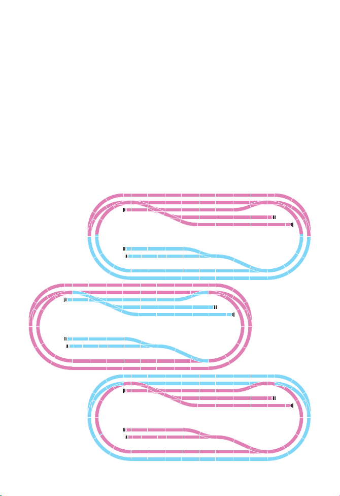
1 Leistungsverteilung auf der Anlage
Um einen oder mehrere Booster einsetzen zu können, muss die Anlage in mehrere
elektrisch getrennte (Versorgungs-) Bereiche eingeteilt werden. Diese Bereiche wer
den dann an unterschiedliche Versorger (Central Station, Booster) angeschlossen. Die
elektrische Belastung sollte in den Versorgungsbereichen etwa gleich sein.
-
Beispiele für die Aufteilung:
zwei Hälften
Fahr- und Rangierbetrieb
Innenkreis und Außenkreis
3
4
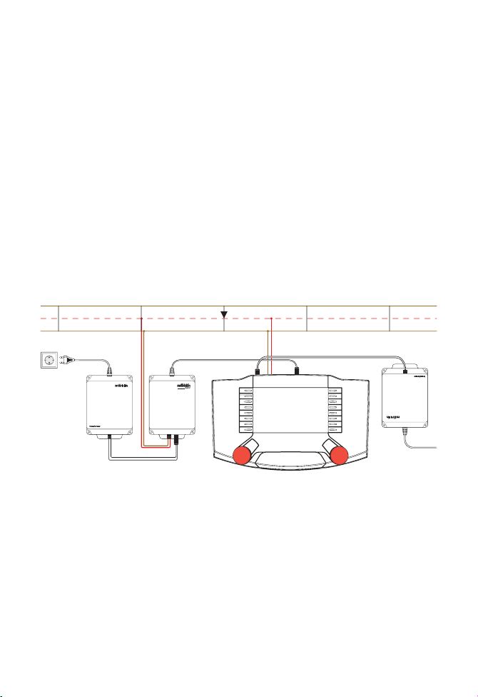
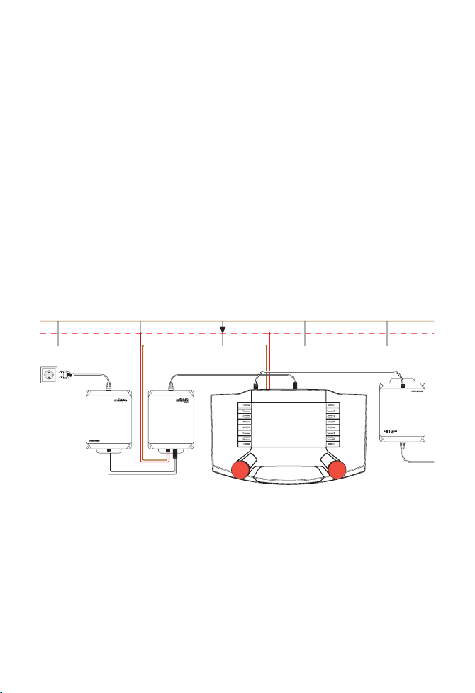
2 Anschluss des Boosters 60174
Zum Anschluss des Boosters sind vorab alle an der Anlage angeschlossenen Transformatoren und Schaltnetzteile vom Stromnetz zu trennen. Jeder Booster bzw. jede
Central Station ist an ein eigenes Netzteil/Transformator anzuschließen. Die Anlage
selbst ist in die geplanten Versorgungsbereiche zu trennen. Die verschiedenen Versorgungsbereiche müssen elektrisch getrennt werden, d.h. dass an den Übergangsstellen
im H0-Gleis der Mittelkontakt isoliert werden muss, die beiden Gleise jedoch zur
Herstellung der „gemeinsamen Masse“ verbunden werden müssen.
Stecken Sie den Booster an der Central Station an der Buchse „60173“ ein und
verbinden Sie den Booster mit beigefügtem Kabel mit den Gleisen (wenn Sie nicht das
beigefügte Kabel verwenden, so achten Sie darauf, dass das Kabel nicht länger als
2,0 m sein darf!). Beachten Sie dabei, dass das rote Kabel (B) an den Mittelleiter (B)
angeschlossen werden muss (die Kabelzuordnungen müssen gleich sein wie bei der
Central Station!).
Wenn Sie weitere Booster 60174 mit der Central Station betreiben wollen, so können
Sie das Terminal 60125 mit der Central Station verbinden und je Terminal bis zu vier
Booster anschließen.
3 Die Anzeige des Boosters
Am Booster 60174 ist bei den Anschlussbuchsen eine rote Leuchtdiode (LED), die
verschiedene Zustände des Boosters anzeigt:
B B
B
B
0 0
0
0

LED aus Der Booster erhält keinen Strom vom Schaltnetzteil/Trafo.
Der Booster hat / wurde auf STOP geschaltet.
Der Booster bekommt kein Signal von der Central Station.
LED leuchtet hell Der Booster erhält Strom vom Schaltnetzteil/Trafo. Das Gleis
LED leuchtet schwach
wird korrekt versorgt.
Über den Booster wird ein Lok-Decoder ausgelesen.
Der Booster arbeitet korrekt. Die Helligkeit der LED nimmt mit
zunehmender Belastung des Boosters ab.
4 Betrieb
Nach dem Einschalten des Boosters dauert es einige Sekunden, bis die rote LED leuchtet. Dann ist der Booster betriebsbereit. Während des Betriebs des Boosters leuchtet die
LED je nach Situation unterschiedlich hell und bestätigt die korrekte Funktion.
Der Booster 60174 meldet verschiedene Daten, wie den Stromverbrauch und die Tempe
ratur im Gerät an die Central Station. Diese kann die Werte unter „Setup-Info“ anzeigen.
5 Sicherheitshinweise
– Der Booster ist ausschließlich zum Gebrauch in trockenen Räumen bestimmt.
– Der Booster sollte nur betrieben werden, wenn er fest auf einer Grundplat
te verbunden ist. Er sollte möglichst an einer gut belüfteten Stelle befestigt
werden und es sollten keine anderen Wärme abstrahlenden Geräte daneben
befestigt sein.
– Den Booster niemals auf einer Unterlage betreiben, die feucht oder leicht
entzündbar ist.
– Die Netzstecker mehrerer Schaltnetzteile/Transformatoren sollten immer
gemeinsam in einer Verteilerleiste angeschlossen werden. Der Anschluss der
Schaltnetzteile/Transformatoren an das Netz oder das Trennen vom Netz darf
immer nur mit dem Netzstecker der Verteilerleiste erfolgen!
– Versorgungskreise müssen getrennt sein, d.h., dass die Gleisbereiche von
Central Station und einem oder mehreren Boostern elektrisch getrennt sein
müssen. Auch die Gleisbereiche von mehreren Boostern dürfen keinen elektrischen Kontakt zueinander haben (nur Mittelleiter isolieren!).
– Beachten Sie beim Anschluss des Boosters die Kabelfarben. Das rote Kabel ist,
so wie auch bei der Central Station, mit dem Mittelleiter zu verbinden.
– Beachten Sie, dass sich der Booster während des Betriebs stark erwärmen
kann. Er sollte deshalb so montiert werden, dass er gut belüftet und nicht neben
anderen Wärmequellen wie Transformatoren betrieben wird.
-
-
5

6 Fehlersuche
Verbindung überprüfen und reparieren.
Warten, bis der Trafo abgekühlt ist und wieder
einschaltet.
Überprüfen Sie die Anschlüsse des Boosters an
der Central Station / am Terminal und am Gleis.
Sie die STOP-Taste.
Das Netzteil durch ein leistungsfähigeres
ersetzen.
-
nehmen.
Boosters / die Anzahl der Verbraucher.
Evtl. den Booster an einer besser belüfteten
Stelle montieren.
Das Netzteil durch ein leistungsfähigeres
ersetzen.
Das Netzteil durch ein leistungsfähigeres
ersetzen.
Das Netzteil ist nicht eingesteckt. Netzteil einstecken.
Die Steckverbindungen des Kabels
zwischen Booster und Netzteil sind
schlecht/beschädigt.
Trafo hat wegen Überhitzung abge
Fehlerbild Mögliche Ursachen Fehlerbehebung
Der Booster gibt keine Leistung
ab. Das Gehäuse ist kalt.
Die LED leuchtet nicht.
6
schaltet.
Der Booster ist nicht richtig ange-
schlossen.
Kurzschluss am Gleis. Beseitigen Sie den Kurzschluss und betätigen
Der Booster ist an ein zu schwaches
Netzteil angeschlossen.
Gerät ist überhitzt. * Booster abkühlen lassen und wieder in Betrieb
Die Central Station meldet eine
Überlast, es gibt aber keinen
Kurzschluss.
Der Booster gibt keine Leistung
ab. Das Gehäuse ist erwärmt.
Die LED leuchtet rot.
Der Booster schaltet oft ab. Der Booster ist überlastet. * Reduzieren Sie den Versorgungsbereich des
Netzteil angeschlossen. *
Netzteil angeschlossen.
Der Booster schaltet ab. Der Booster ist an ein zu schwaches
Zu geringe Leistung Der Booster ist an ein zu schwaches
* Beachten Sie hierzu auch die Anzeige in der Central Station unter Setup, Info!

The power requirements for a layout increase quickly as the layout grows in size, until
the required power can no longer be supplied by the central controller alone. At that
point the power supply for the layout must be supplemented by one or more Boosters.
The Central Station can provide a power output of up to approximately 2.5 amps (depending on the switched mode power pack / transformer being used). A 60174 Booster
in conjunction with the 60052/60055 transformer or the 60061 switched mode power
pack can contribute a power output of up to approximately 3 amps.
1 Power Distribution on a Layout
A layout must be divided into several electrically separate power consumption areas in
order to use one or more Boosters. These areas are then connected to different power
supplies (Central Station, Booster). The electrical load should be about equal in the
power consumption areas.
Examples for Dividing a Layout up into Power Consumption Areas:
Two halves
Main Line and Switching Operation
Inner Loop and Outer Loop
7
8
2 Connections for the 60174 Booster
All transformers and switched mode power packs connected to the layout must be unplugged from the household current before connecting the Booster to the layout. Each
Booster and each Central Station must be connected to its own switched mode power
pack / transformer. The layout itself must be separated into planned power consumption areas. The different power consumption areas must be separated from each other
electrically. This means that the contact for the center conductor must be isolated
in H0 track at the transition points between power consumption areas. Both of the
running rails at these points must remain connected to produce a “common ground“.
Plug the Booster into the Central Station at the socket marked “60173“ and connect
the Booster to the track with the wire included with it (the Booster) (if you don‘t use
the wire included with the Booster, then make sure that the wire is no longer than 2.0
meters / 78“!). Make sure when making the connections that the red wire (B) is connected to the center conductor (B) (The assignments for the wires must be the same
as for the Central Station!).
If you want to operate additional 60174 Boosters with the Central Station, then you can
connect the 60125 Terminal to the Central Station and connect up to four Boosters to
each Terminal.
3 The Display for the Booster
Am Booster 60174 ist bei den Anschlussbuchsen eine rote Leuchtdiode (LED), die
verschiedene Zustände des Boosters anzeigt:
B B
B
B
0 0
0
0

LED off The Booster is not receiving current from the switched mode
LED on bright
LED on dim
power pack / transformer.
The Booster has / was switched to STOP.
The Booster is getting no signal from the Central Station.
The Booster is receiving current from the switched mode power
pack / transformer. The track is being powered correctly.
A locomotive decoder is being read via the Booster.
The Booster is working correctly. The brightness of the LED
decreases as the load on the Booster increases.
4 Operation
After the Booster has been turned on, it takes a few seconds before the red LED comes
on. The Booster is then ready for operation. While the Booster is in operation, the LED
lights up with different levels of brightness, depending on the situation, and confirms the
correct function.
The 60174 Booster reports different data to the Central Station such as the current con
sumption and the temperature. The Central Station can display these values at “Setup
Information“.
5 Safety Notes
– The Booster is designed only for operation in dry areas.
– The Booster should be operation only when it is securely mounted on a base or
platform. It should be mounted if possible in a well ventilated location and no
units putting off heat should be mounted near it.
– Never operate the Booster on a base or platform this wet or easily set on fire.
– The power cord plugs for several switched mode power packs / transformers
should always be connected to a common power strip. The power strip must
always be unplugged from the household current before plugging or unplugging
switched mode power packs / transformers at the power strip!
– Power consumption areas must be separated from each other, i.e. the track areas
for the Central Station and for one or more Boosters must be separately elec
trically from each other. Also, the track areas for two or more Boosters may not
have any electrical contact with each other (Isolate the center conductor only!).
– Pay attention to the colors of the wires when connecting the Booster. As with
the Central Station, the red wire must be connected to the center conductor.
– Please note that the Booster can become rather warm during operation. It
should therefore be mounted in a location where there is good ventilation and
where there are no other sources of heat such as transformers nearby.
-
-
9

6 Troubleshooting
Check the connection and repair.
Wait until the transformer has cooled off and
turn it on again.
-
Check the connections from the Boosters to the
Central Station / to the Terminal and to the track.
button.
Replace the power pack with a more powerful
unit.
ting it again.
Booster / the number of power consumption
users.
If necessary, mount the Booster in a better venti
lated location.
Replace the power pack with a more powerful
unit.
Replace the power pack with a more powerful
unit.
The power pack is not plugged in. Plug in the power pack.
The plug connections for the wire bet-
ween the Booster and the transformer
are bad/damaged.
Transformer has turned off due to
Description of Malfunction Possible Causes Correction of Malfunction
The Booster is not providing any
power. The housing is cold.
The LED does not light up.
10
overheating.
The Booster is not correctly connec-
ted.
Short circuit in the track. Correct the short circuit and press the STOP
The Booster is connected to a power
pack that is too weak. *
The unit is overheated. * Let the Booster cool down and then try opera-
-
wer. The housing is warm to the
touch. The LED is lighting up red.
The Booster is providing no po
The Central Station is registering
an overload, but there is no short
circuit.
The Booster shuts off often. The Booster is overloaded. * Reduce the power consumption area for the
pack that is too weak. *
The Booster is connected to a power
pack that is too weak.
Too little power.
The Booster shuts off. The Booster is connected to a power
* In this situation, also pay attention to the display on the Central Station at Setup, Information!
La puissance requise par le réseau est proportionnelle à sa taille et peut donc être telle que la centrale seule ne suffise plus à couvrir les besoins. L’alimentation du réseau
doit alors être complétée par un ou plusieurs boosters.
La Central Station, quant à elle, peut fournir une puissance maximale d’env. 2,5 A (en
fonction du convertisseur/transformateur utilisé). Combiné au transformateur réf.
60052 ou au convertisseur réf. 60061, le booster réf. 60174 peut fournir une puissance
maximale d’env. 3 A.
1 Distribution de la puissance sur le réseau
L’utilisation d’un ou de plusieurs boosters requiert le partage du réseau en plusieurs
zones (d’alimentation) électriquement séparées. Ces zones sont alors raccordées à
différentes sources d‘alimentation (Central Station, booster). La charge électrique doit
être à peu près identique dans toutes les zones d‘alimentation.
Exemple de distribution:
Division en deux moitiés
Conduite et manœuvres
Cercle intérieur et cercle extérieur
11
 Loading...