

Page 1
No320S preamplifier
RS-232 control guide
1
Page 2

Overview
Overview The Mark Levinson No320S preamplifier is equipped with an RS-232
control port. A complete set of command inputs and status outputs allow control of
the No320S by an external control system (such as AMX or Crestron). This guide
contains connection details and the RS-232 command list.
Contacting
Technical
Support
Phone
860-346-0896
9am to 5pm EST Monday thru Friday
Fax
860-347-6251
Please allow 24hrs for reply
Email
madts@harman.com
Please allow 24hrs for reply
2
Page 3
Connection
RS-232 Port
Location
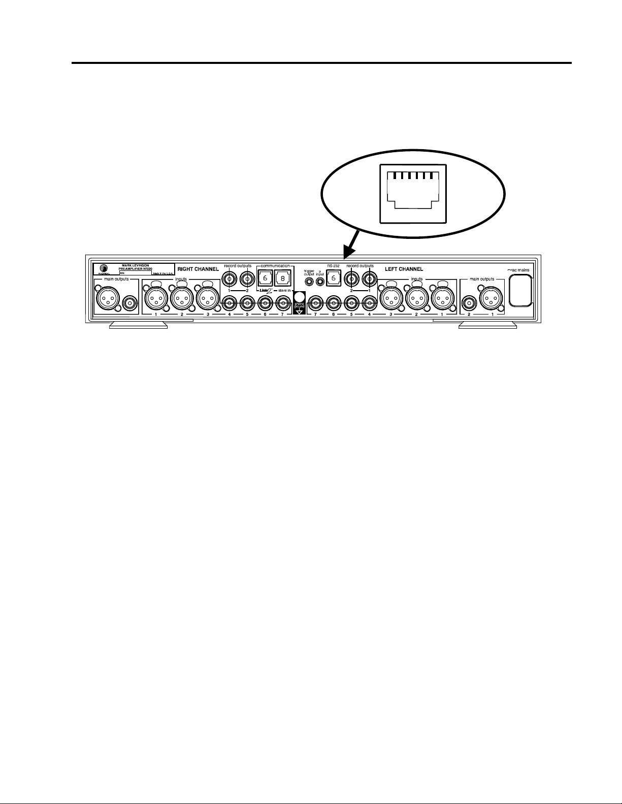
RS-232 control is through an RJ-11 connector located on the back of the No320S next
to the IR output. This connector has 6 pins of which only three are used for
communication.
RX TX GND
RS-232 Port Pin
Configuration.
The No320S will receive control data on pin 2 Data Receive and transmit status data
on pin 3 Data Transmit. The connection Cable between the No320S and the control
device will need to be configured so that the No320S’s receive is connected to the
control devices transmit. Please refer to the product owner’s manual for the control
device you are using for RS-232 port type and configuration.
Pin 2 Rx from the PC / Data Receive
Pin 3 Tx to the PC / Data Transmit
Pin 5 Digital system ground
3
Page 4

RS-232 Control
Cable
Madrigal Audio Labs offers several parts to help communicate via RS-232 to the
No320S. The following parts can be order from Madrigal Audio Labs Technical
Support.
Part # Description
MRC878 DSUB9 to RJ-11 Adaptor and 2 meter RJ-11 to RJ-11 Cable
MRC808 DUB9 to RJ-11 Adaptor
MLC732 2 meter RJ-11 to RJ-11 Cable
For general purpose and short cable runs to the No320S, Part # MRC878 contains
everything needed.
For cable lengths of more then 2 meters - Part # MRC808 and the length of cable
needed should be ordered.
RS-232 control units with port types other then DSUB9 will need to have the cable
constructed. To construct a cable please follow the example below.
Control Cable
Example
Before
Constructing the
Communications
Cable
Cable Layout
As an example on making the cable we will use the most common connector used,
which is a DSUB9. The No320S only needs 3 pins to control the unit via RS-232. As
mentioned earlier the No320S’s pin 2 Data Receive must connect to the control
devices Transmit. Please read the notes below before constructing the RS-232
cable.
q Verify Control Devices RS-232 Port Type and Configuration – Refer to Control
Device Owners Manual
q Determine length of cable needed – Check the control device owners manual for
length limitations
q Have all available parts
o Length of Cable needed
o RJ-11 Connector
o Connector type used by RS-232 device
The following diagram shows how to construct a basic DSUB9 to RJ-11 Cable.
Cable Connections
No320S RS-11
Pins
1 – NOT USED
2 – Data Receive
3 – Data Transmit
4 – NOT USED
5 – Digital Ground
6 – NOT USED
NO CONNECTION
-----Connect to-----
-----Connect to-----
NO CONNECTION
-----Connect to-----
NO CONNECTION
Controller DSUB9
Pins
3 – Data Transmit
2 – Data Receive
5 – Digital Ground
4
Page 5

Diagram 2 – RJ- 11 to DSUB9 Cable
p
Pa rts Use d fo r C a b le
(1)
- 9 pin DSUB Female Connector
(2)
- 6 pin RJ-11 Connector
(3)
- 9 pin DSUB Housing
(4)
- 6 Conductor Data / Phone Cable
H0063 (length in feet)-ND 910-2319
Digikey Pa rt# Ra diosha ck Pa rt #
A2047-ND 276-1537
A9027-ND 279-421
A9001-ND 276-1539
(2) - 6 Pin RJ-11 Connec tor
NO TE O rie nta tio n of
RJ-11 with C lip Fac ing
Dow n
St rip Insula tio n p e r RJ-11
ma nufac turers
In stru c tio ns
A sse m b l e
(3) - 9 pin DSUB Housing
e r m a nu fa c t ure rs spe c ific at ion s
(1) - 9 p in DSUB Fema le Inside View
(4) - 6 Conductor Data / Phone Cable
Cut wires
1 / 4 / 6
from ca b le
NO TE O rie nt a tio n of
wires and Attach as
sh o w n
5
Page 6

Command list
Settings: 38.4K baud, 1 stop bit, no parity
Format: !<command><cr> or !Vxx.x<cr>
The '!' is used as a framing character and can be sent any time to reset the
packet reception code. Note that all commands are 5 bytes ( '!' + 3char command
+ <cr> ) with the exception of the direct volume command which is 7 bytes ( '!' +
'V' + 4 bytes data + <cr> ) <cr> = 0x0d, carrage return.
Example: !GI1<cr> ( selects input 1 on No320S)
Keys:
COMMAND DESCRIPTION
KVD Volume "key" down
KVU Volume "Key" up
KBA Balance Key
KSU Setup Key
KEN Enter Key
KST Standby Key
KMU Mute Key
KMO Mono Key
KIP Input select previous "key"
KIN Input select next "key"
KPO polarity key
KDI Display Intensity key
Note on ramping volume:
Repeated “EV_VOL_DOWN” or “EV_VOL_UP” key commands must be
sent at less than 150mS intervals to cause a smooth, accelerated ramping of
volume like the effect of holding the volume up or down key on the remote
control.
Directs:
COMMAND DESCRIPTION
GOP Go to Operate mode
GST Go to Standby mode
GMU Go to mute
GMN Restore volume
GI1 Go to input 1
6
Page 7

Status:
GI2 Go to input 2
GI3 Go to input 3
GI4 Go to input 4
GI5 Go to input 5
GI6 Go to input 6
GI7 Go to input 7
Note: “GI7” selects either input 7 or phono input if installed.
GBA Go to balance mode
GBE Exit balance mode
IOF Go to display intensity 0
I25 Go to display intensity 25%
I50 Go to display intensity 50%
IFU Go to display intensity 100%
COMMAND DESCRIPTION
MON Enable RS232 status updates
(default)
MOF Disable RS232 status updates
Note: The monitor on/off setting is not saved
and restored through power off->on cycles
Volume direct:
COMMAND DESCRIPTION
Vxx.x Set volume level directly
Note: Rounds to nearest whole dB step for volumes less that
Example: V65.0<cr> (sets No320S volume to 65.5)
Query:
COMMAND DESCRIPTION
QAL Request entire current No320S status
Note: Sends all 6 status lines shown below regardless of
23.0
monitor on/off
7
Page 8

Status Update:
Any change in the following 6 control keys will automatically send out the
corresponding ASCII string.
CONTROL KEY RETURNED VALUE COMMENT
Select knob
Volume knob
Mute
Mono
Polarity
Standby
1:IN:<1-7>:<input alias><cr> or
1:IN:NONE<cr> if no current valid input
selection input alias> is max 7 chars, no
null termination
2:VOL:xx.x<cr> or 2:VOL:OFF<cr>
3:MUTE:ON<cr> or 3:MUTE:OFF<cr>
4:MONO:ON<cr> or 4:MONO:OFF<cr>
5:POL:ON<cr> or 5:POL:OFF<cr>
6:STDBY:ON<cr> or 6:STDBY:OFF<cr>
input alias = first 7 ascii
characters from No320S
LED display.
xx.x = last 4 ascii characters
from No320S display
ON = user mute engaged,
OFF = normal volume
ON = mono , OFF = normal
stereo
ON = polarity reversed, OFF
= normal
ON = standby active, OFF =
normal operating mode
8
 Loading...