

Mark Levinson No 26 Owners manual
DEFEAT
0° 180° STEREO MONO
AUX 1
INPUT
MONITOR
TAPE 1
MONITOR SELECTORRECORD SELECTOR
TAPE 2
PHONO/
AUX 2
TUNER
CD
INPUT
SELECTOR BALANCE 1 BALANCE 2
TAPE 1
TAPE 2
MADRIGAL AUDIO LABORATORIES
DUAL MONAURAL
PREAMPLIFIER
Nº 26
5
4
6
3
2
1
OFF
OUTPUT
LEVEL
7
8
9
10
-3
2 7
0dB
+1
-1
-2
-4
+2
+3
+4
+5
-5
0dB
+1
-1
-2
-3
-4
+2
+3
+4
-5
+5
1
3 4 5 6 6
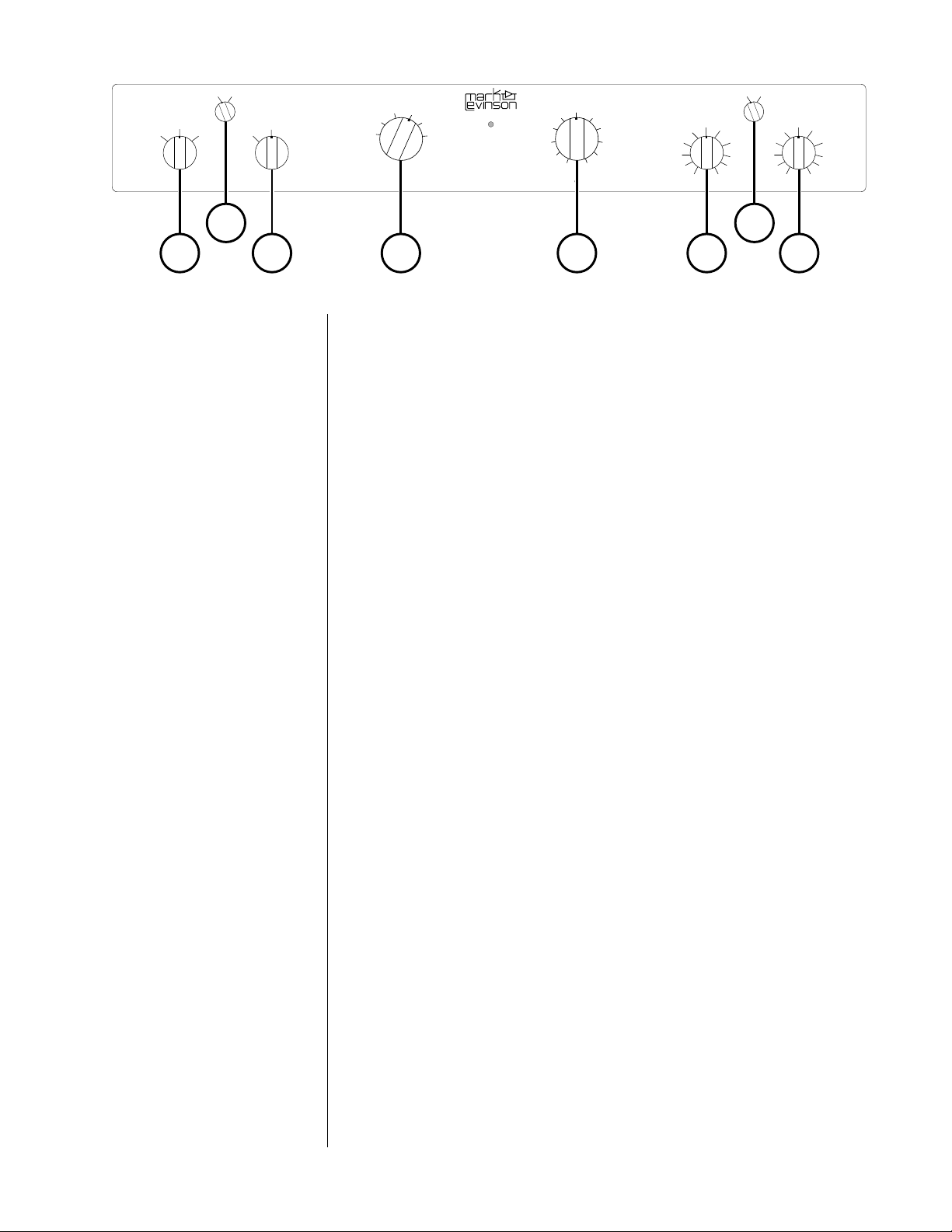
Front panel
1 RECORD SELECTOR
Selects between the program source (selected via the INPUT
SELECTOR), and either of two tape monitor inputs (selected via the
MONITOR SELECTOR).
In the DEFEAT position, the tape outputs are disconnected.
In the INPUT position, the tape outputs are connected while still
monitoring the selected source.
In the MONITOR position, the selected tape machine can be
monitored without affecting the signal at the tape outputs.
Note: Because of the switching arrangement employed in
the Nº26, we recommend that while making a critical
recording you don't operate the RECORD SELECTOR switch.
If you wish to monitor the signal from tape, set the RECORD
SELECTOR to MONITOR and use your tape machine's monitor
switch to switch between input and tape.
20°/180°
In the 0° position, the signal at the main outputs is in phase with the
input signal. In the 180° position, the output signal is inverted 180
degrees. This allows you to optimize your system's sonic
performance based on recording/mastering processes used for a
specific program.
The 0°/180° switch doesn't affect the tape outputs.
3 MONITOR SELECTOR
When the RECORD SELECTOR is in the MONITOR position, this selects
between the TAPE 1 and TAPE 2 inputs.
4 INPUT SELECTOR
Selects one of the six inputs: CD, TUNER, AUX 1, PHONO/AUX 2
(depending on the installed option), TAPE 1, or TAPE 2.
1

5 OUTPUT LEVEL
Adjusts volume at the main outputs.
The OUTPUT LEVEL control doesn't affect the tape outputs.
Note: In some systems, particularly those with high-efficiency
loudspeakers, high-gain amplifiers, and balanced
interconnections, it's possible that you may hear some lowlevel sound through your loudspeakers
OUTPUT LEVEL control set to OFF
.
even with the Nº26's
If this occurs with all inputs, reduce the
internal switches). If this occurs only when listening to the
source connected to the Nº26's optional balanced input,
reduce the
See "Set-up and installation."
6 BALANCE 1, BALANCE 2
Adjusts volume at the main outputs.
The BALANCE controls don't affect the tape outputs.
7 STEREO/MONO
Selects between monaural or stereo mode at the main output.
The STEREO/MONO switch doesn't affect the tape outputs.
balanced input gain
(via the internal switches).
line gain
(via the
2
2 4 4
10
BALANCED OUTPUT
RL
1
PRECAUTION
MAIN OUT TAPE 2 OUT TAPE 1 OUT
RLRLRL
TUNER TAPE 2 IN TAPE 1 IN
3
5 5 7 8 9
POWER
SUPPLY
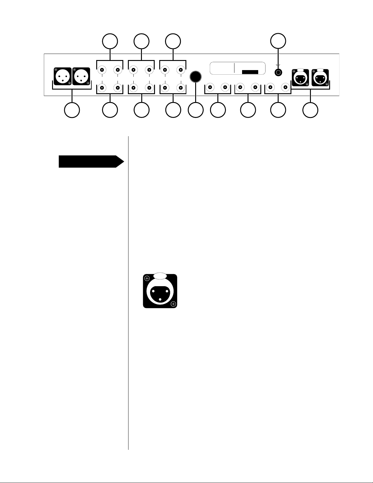
Rear panel
Disconnect all associated equipment from the AC mains BEFORE
making any signal connections and applying power to the Nº26/PLS-
226.
1 BALANCED OUTPUT
If your power amplifier is equipped with balanced input
connectors, it's best to connect it to the Nº26 via these connectors,
particularly if long cable lengths are required.
Connect the right-channel and left-channel BALANCED OUTPUT of
the Nº26 to the appropriate balanced inputs of the power
amplifier.
INPUT
6
DUAL MONAURAL
PREAMPLIFIER
CD AUX 1 PHONO/AUX 2
RL RL RL
Nº 26
DESIGNED AND MANUFACTURED
IN U.S.A. BY
MADRIGAL
AUDIO LABORATORIES INC.
S/N:
OPTIONAL BALANCED INPUT
RL
AUX 2
PUSH PUSH
11
The pin assignments of these XLR-type male outputs are:
PUSH
21
3
Pin 1: Signal ground
Pin 2: Signal + (non-inverting)
Pin 3: Signal – (inverting)
Connector ground lug: chassis ground
Refer to your power amplifier's operating manual to verify that the
pin assignments of its input connector correspond to the Nº26. If
not, wire the cable so that the appropriate output pin connects to
the equivalent input pin.
2 MAIN OUT
Connect these outputs to the right-channel and left-channel
inputs of your power amplifier or electronic crossover.
These outputs are affected by the OUTPUT LEVEL control on the
front panel of the Nº26.
3 TUNER
Accepts right-channel and left-channel signal leads from a tuner
or other line-level source equipment.
3

4 TAPE 1 OUT, TAPE 2 OUT
Connect these outputs to the right-channel and left-channel tape
inputs of your tape machine.
5 TAPE 1 IN, TAPE 2 IN
Accept right-channel and left-channel signal leads from the tapeoutput connectors of a tape machine. These inputs can also be
used with other line-level source equipment.
These outputs are unaffected by the OUTPUT LEVEL control on the
front panel of the Nº26.
6 POWER SUPPLY INPUT
Accepts one end of the DC cable that connects the Nº26 to the
PLS-226.
7CD
Accepts right-channel and left-channel balanced signal leads
from a CD player or other line-level source equipment.
8 AUX 1
Accepts right-channel and left-channel signal leads from line-level
source equipment.
9 PHONO/AUX 2
If your Nº26 is equipped with the phono option, connect your
turntable's right-channel and left-channel signal leads to these
inputs.
If your Nº26 isn't equipped with a phono option, these inputs will
accept signal leads from any line-level source equipment.
10 Ground binding post
Connect your tonearm's ground lead to this binding post.
11 OPTIONAL BALANCED INPUT
If your Nº26 is equipped with the balanced input option, connect
the right-channel and left-channel balanced line-level signal leads
from source equipment with balanced output.
The pin assignments of these XLR-type female input connectors
are:
Pin 1: Signal ground
12
3
Refer to the operating manual of your balanced-output line-level
source to verify that the pin assignments of its output connector
correspond to the Nº26. If not, wire the cable so that the
appropriate output pin connects to the equivalent input pin.
Pin 2: Signal + (non-inverting)
Pin 3: Signal – (inverting)
Connector ground lug: chassis ground
4

Unpacking and placement
Unpacking
Placement
Ventilation
Unpack your Nº26 Preamplifier and PLS-226 Power Supply, and keep all
packing materials for future transport. Remove all accessories from the
cartons.
Carefully inspect the product for damage and flaws. If you find any,
see your Mark Levinson dealer immediately.
Place the Nº26 as close as possible to the source equipment, thus
keeping interconnect cabling as short as possible. It may be placed
on a shelf or in a cabinet where it's convenient to operate.
A one-meter DC cable is provided to connect the PLS-226 to the Nº26.
This allows you to place the PLS-226 so that it won't induce hum in the
Nº26 and other sensitive components. If you're placing the Nº26 and
PLS-226 adjacent to each other, place the PLS-226 to the right of the
Nº26 (viewed from the front). You should also place associated
equipment so that it doesn't induce hum in the Nº26 and other
sensitive components.
Be sure to allow 3 to 4 inches of clearance above both the Nº26 and
the PLS-226, to allow heat dissipation through air circulation.
Drawings are included in this manual to facilitate special installations
and custom cabinetry (see "Dimensions").
PRECAUTION
For your protection, review "Important safety instructions" before you
install your Nº26.
5
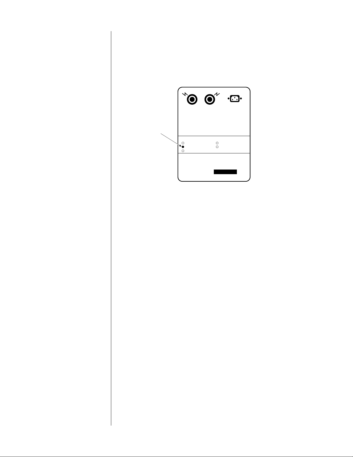
Voltage selection
The PLS-226 is factory-set (internally) for 100V, 120V, 200V, 220V, or
240V AC mains operation @ 50 or 60Hz. Make sure that the label on
the bottom of the PLS-226 indicates the correct AC operating voltage
for your location.
PLS-226 bottom-panel
label
PLS-226 POWER SUPPLY
AC INPUT
210 – 240VAC~
230 – 250VAC~
~50 – 60HZ
Voltage
indication
DC OUTPUTS
WARNING: BEFORE ATTEMPTING TO
OPERATE THIS DEVICE, REFER TO
OWNER'S MANUAL FOR PROPER
OPERATING INSTRUCTIONS AND SAFETY
PRECAUTIONS. HAZARDOUS VOL T AGE
AVAILABLE INSIDE; DISCONNECT AC~
MAINS CABLE BEFORE REMOVING COVER.
OPERATING VOLTAGE:
90 – 110VAC~
105 – 125VAC~
180 – 220VAC~
100 – 120VAC~
2A SLO–BLO 250VAC 3AB
MAINS
200 – 240VAC~
FUSES:
1A SLO–BLO 250VAC 3AB
SERIAL NO.
DESIGNED AND MANUFACTURED IN U.S.A. BY
MADRIGAL AUDIO LABORATORIES INC.
If the voltage indicated is incorrect, see your Mark Levinson dealer.
If you wish to change the AC operating voltage of the Nº26/PLS-226,
see your Mark Levinson dealer.
The Nº26/PLS-226 can be powered by a normal 15-ampere AC mains
line. If other devices are also powered from the same AC line, their
additional power consumption must be taken into account.
6

Set-up and installation
Connectors and cables
Internal adjustments:
line gain
The Nº26 incorporates RCA-type and XLR-type connectors for audio
signal input and output.
The Madrigal-designed RCA-type connectors used for single-ended
audio interconnection are a great improvement over ordinary RCAtype connectors. The gold-plated XLR-type connectors employed are
of European design, and are made to professional standards.
When connecting the Nº26 to source equipment and power
amplifiers, we recommend Madrigal Audio Laboratories HPC
Interconnect Cable. HPC is available in various lengths, terminated
with RCA, XLR, and Camac connectors. See your Mark Levinson
dealer for more information.
The Nº26 offers internal gain adjustment of the line amplifiers, in 6dB
steps via two four-pole miniature rocker switches (one for each
channel). These switches have been factory-adjusted at the lowest
gain position (6dB of line gain in single-ended operation, and 12dB of
line gain in balanced operation). In practice, you should have enough
gain so that normal listening is possible with the OUTPUT LEVEL set at
approximately 6.
If you wish to increase the line gain, see "Making the internal
adjustments;" refer to the table below for the proper switch positions
for each gain setting.
Line gain settings
Internal adjustments:
phono gain
Phono gain settings
(high-gain option)
Phono gain settings
(low-gain option)
Switch Gain
#1 #2 #3 #4 Single-Ended Output Balanced Output
On On Off Off 18dB 24dB
Off On On Off 12dB 18dB
Off Off On On 6 dB 12dB
The Nº26 is available with either a high-gain or low-gain phono option.
Each option offers two internally adjustable gain settings via two twopole miniature rocker switches, one for each channel. The high-gain
and low-gain phono options have been factory-adjusted at the lowest
gain settings (58dB and 38dB, respectively).
If you wish to increase the gain, see "Making the internal adjustments;"
refer to the tables below for the proper switch positions for each gain
settings.
Switch
#1 #2 Gain Nominal Cartridge Output (3.54 cm/sec)
On Off 58dB .2mV - .6mV
Off On 64dB .2mV and Lower
Switch
#1 #2 Gain Nominal Cartridge Output (3.54 cm/sec)
On Off 38dB Greater than 2.0mV
Off On 44dB 2.0mV and Lower
7
 Loading...