

Page 1

0
N
INTEGRATED AMPLIFIER QUICK-START GUIDE
585
Page 2

Page 3

TABLE OF CONTENTS
About This Document 1
Installation Considerations 2
Unpacking, Placement and Ventilation,
Power Requirements, Operating States
Getting Started 4
Front-Panel Overview, Rear-Panel Overview,
Remote Control Overview
Quick Setup and Listen 11
Remote Control, Initial Connections
Troubleshooting 14
Specifications 15
TABLE OF CONTENTS / ABOUT THIS DOCUMENT
ABOUT THIS DOCUMENT
This quick-start guide contains all the information
you will need to unpack your N
rest of your audio system, turn it on and have a first
listen. Before you attempt more extensive use of this
sophisticated integrated amplifier, you must read the full
N0585 User Guide
www.marklevinson.com.
information about features, operations, adjustments,
alternate connections and networking that will enhance
0
your N
585’s operation and performance.
, which is available online at
0
585, connect it to the
The User Guide contains
1N0585 INTEGRATED AMPLIFIER / QUICK-START GUIDE
Page 4

INSTALLATION CONSIDERATIONS
INSTALLATION CONSIDERATIONS
UNPACKING
When unpacking your N0585:
• Save all packing materials in case you need to ship your
0
N
585 in the future.
• Inspect your N
If you discover damage, contact your authorized
Mark Levinson
appropriate claims.
• Locate and remove the accessory box from the shipping
carton. Make sure that all of the items listed below are
included. If any are missing, contact your authorized
Mark Levinson dealer.
1 x IEC power cord (terminated according to the region to
which the unit is shipped)
0
1 x N
585 remote control
2 x AAA alkaline batteries
1 x #1 Phillips screwdriver
1 x Pair white gloves (for use during unpacking and initial
setup)
0
585 for signs of damage during shipment.
®
dealer for assistance in making
PLACEMENT AND VENTILATION
• Install the integrated amplifier on a shelf with nothing
above it, such as the top shelf in an open rack, to
ensure proper ventilation. Do NOT install the integrated
amplifier inside of an enclosed cabinet or rack.
• Ensure that you install the integrated amplifier on a
solid, flat and level surface.
• Install the integrated amplifier as close as possible to
associated audio components to keep interconnecting
cables as short as possible.
• Select a dry, well-ventilated location that is out of direct
sunlight.
• DO NOT expose the N
steam, smoke, dampness, or excessive dust.
0
585 to high temperatures, humidity,
0
1 xN
585 Quick-Start Guide
NOTE: The N0585 User Guide is available for download
online at www.marklevinson.com.
Please register your N0585 within 15 days of your purchase.
Register online at www.marklevinson.com. Retain your
original, dated sales receipt as proof of warranty coverage.
2 N0585 INTEGRATED AMPLIFIER / QUICK-START GUIDE
Page 5

INSTALLATION CONSIDERATIONS
POWER REQUIREMENTS
The Nº585 is configured at the factory for 100, 115, or 230
VAC power operation at 50Hz or 60Hz. Before operating the
amplifier, ensure that the power label on the rear panel
near the AC input connector indicates the correct operating
voltage. A detachable IEC power cable intended for use in the
region where the N
0
585 is sold is included.
Connection to an AC voltage other than that for which the
0
N
585 is intended can create a safety and fire hazard and
may damage the unit. If you have any questions about
the voltage requirements for your N
0
585 or about the line
voltage in your area, contact your authorized Mark Levinson
dealer before plugging the N
0
585 into an AC power outlet.
WARNING! MAKE SURE all components in the
audio system are properly grounded. Do NOT defeat
the safety purpose of polarized or grounding-type
plugs with “ground-lifter” or “cheater” adapters.
Doing so may cause dangerous voltage to build up
between components, which may result in personal
injuries and/or product damage.
NOTE: The N0585 is capable of passing remarkable
sound at exceptional power levels. Depending on your
listening habits, the demands of your loudspeakers
and the number of power amplifiers present in your
system, it is possible that your electrical service
may become the limiting performance factor in your
system.
OPERATING STATES
The N0585 has three operating states:
Off: The AC mains power is disconnected by using the
0
N
585’s rear-panel Power switch or by removing the power
cord from the rear panel.
Standby: The N
can be selected via the Setup menu: Green, Power Save,
and Normal.
Green:
This mode removes power from almost all of the
0
N
585’s circuits, allowing the unit to be activated only via
an IR control signal, a 5V – 12V trigger or a press of the
Standby button. This mode provides maximum power
conservation and is the factory-default Standby mode.
Power Save:
audio circuits, but keeps the control circuitry powered
and ready to receive commands from either the front
panel controls or the remote control. This mode provides
moderate power conservation.
Normal:
its audio outputs, but keeps all of its control and audio
circuits powered. This mode provides the least amount
of power conservation but allows the N
to remain warmed up to deliver optimal performance at
all times.
On: The entire N
outputs are active.
0
585 Standby mode has three settings that
This mode removes power from the N0585’s
This mode shuts off the N0585’s display and mutes
0
585’s audio circuits
0
585 is powered up and all configured
If this case occurs, consider installing a dedicated AC
circuit for the system. If more than one AC circuit is
providing power to your system, contact a licensed
electrician to ensure that all components are operating
with the same solid, low-impedance ground reference.
You should unplug the N0585 from the AC wall outlet during
lightning storms and extended periods of non-use.
CAUTION: BEFORE moving the N
0
585, make sure it is
powered off by removing the power cord from the AC
power outlet and the unit's rear panel.
0
The N
585 has an Auto Off feature that automatically places
it into the Standby mode after 20 minutes of no user control
input or audio signal passing through the unit. The factorydefault setting for the Auto Off feature is on (engaged). You
can turn the Auto Off feature off (disengaged) in the Setup
menu.
3N0585 INTEGRATED AMPLIFIER / QUICK-START GUIDE
Page 6
GETTING STARTED
GETTING STARTED
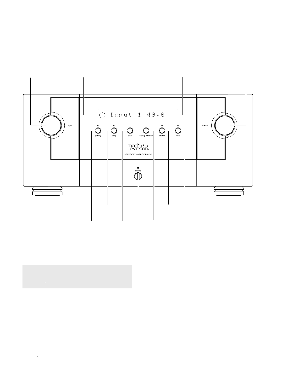
FRONTPANEL OVERVIEW
Select
Knob
IR
Receiver
Polarity Button
and LED
Setup Button
and LED
Enter
Button
Standby
Button
and LED
Display
Intensity
Button
Front-Panel
Balance
Button and
LED
Display
Mute Button
and LED
Volume
Knob
Front-panel controls/indicators
NOTE: For complete information about the functions of
the front-panel controls and their settings parameters,
see the
Select knob:
N0585 User Guide.
at www.marklevinson.com.
Rotate this knob to select the desired input to
send to the Speaker outputs and Line outputs. The name
and volume level of the selected input are indicated on the
Front-Panel display.
(Note: The Select knob will bypass any
input for which the Input Name Setup menu parameter has
been set to “Unused.”
IR receiver:
The IR receiver receives commands from
the included remote control when the N
4 N0585 INTEGRATED AMPLIFIER / QUICK-START GUIDE
)
0
585 is not being
controlled via its rear-panel IR Input connector (see
Panel Overview,
Polarity button and LED:
page 7, for more information).
Pressing this button inverts the
Rear-
absolute polarity of the signal. The LED illuminates when
the signal's polarity is inverted.
Setup button and LED:
Setup menu, which you can use to customize the N
Press this button to display the
0
585 to
suit your other system components, individual preferences
and listening space. The Setup LED lights when the Setup
menu is active.
Enter button:
Press this button to select or deselect a menu
item when the Setup menu is displayed. The Enter button
does not function during normal operation.
Page 7

GETTING STARTED
Display Intensity button:
intensity of the N
Press this button to change the
0
585’s front-panel Display characters
and its front-panel LEDs. Multiple presses of the Display
Intensity button cycle through the available brightness
levels: High, Medium, Low, and Off.
Balance button and LED:
to-right channel balance of the Speaker outputs (
Press this button to set the left-
and the
Line outputs, if you have set them to Variable in the Setup
menu)
. The Balance LED lights when the balance function
is active.
NOTE: When the balance function is inactive, the
Balance LED remains lit if the left-to-right channel
balance of the Main output connectors is offset.
Mute button and LED:
the level of the speaker outputs (
have set them to
Press this button to mute and unmute
and the Line outputs, if you
Variable
in the Setup menu) by the amount
determined in the Setup menu. The LED lights when the
mute function is active.
Front-Panel display:
display provides information about the N
This 16-character alphanumeric
0
585’s operating
status. During normal operation it indicates the name and
volume level of the selected input.
Standby button and LED:
Press this button to put the N0585
into and out of the Standby mode. The LED illuminates
when the N
0
585 is On. When the N0585 is in either the
Green, Normal or Power Save Standby mode it flashes
slowly.
Volume knob:
of the Speaker outputs
them to Variable in the Setup menu)
Turn this knob to adjust the volume level
(and of the Line outputs if you have set
. The minimum volume
level is OFF; the maximum volume level is determined in the
Setup menu.
Whenever you select an input the N
0
585 applies the volume
offset selected for it in the Setup menu to the Speaker output
volume level
(and to the Line output volume level, if you have
set the Line outputs to Variable in the Setup menu).
5N0585 INTEGRATED AMPLIFIER / QUICK-START GUIDE
Page 8

GETTING STARTED
REARPANEL OVERVIEW
Right Channel
Loudspeaker
Binding Posts
Right Channel
Balanced Analog
Input Connector
Right Channel
Line Output
Connector
Right Channel
Single-Ended Analog
Input Connectors
Left Channel
Single-Ended Analog
Input Connectors
Left Channel
Balanced Analog
Input Connector
Left Channel
Line Output
Connector
Left Channel
Loudspeaker
Binding Posts
AES/EBU
Digital Input
Connector
Coaxial
Digital Input
Connectors
Optical
Digital Input
Connectors
USB
Port
Ethernet
Port
IR Input
Connector
RS-232
6 N0585 INTEGRATED AMPLIFIER / QUICK-START GUIDE
Port
Power
Switch
AC Mains
Connector
USB Digital
Connector
Trigger Output
Connector
Trigger Input
Connector
Page 9

GETTING STARTED
NOTE: For complete information about the rearpanel connections, see the
N0585 User Guide.
at www.
marklevinson.com.
Left and right channel loudspeaker binding posts:
The
Nº585 utilizes custom-made, gold-plated, high-current
loudspeaker binding posts. The positive binding posts,
labeled + (positive), are red; the negative binding posts are
black and are labeled – (negative).
The binding posts can accommodate speaker cables
terminated in untinned bare wire, spade lugs and banana
plugs.
CAUTION: DO NOT OVERTIGHTEN the binding posts. The
innovative design of these binding posts provides more
leverage; hence, high-contact, tight pressure connections
are achieved when finger-tightened. DO NOT FORCE the
binding post “wings” over a bent or oversized connector.
Doing so may damage the binding post.
NOTE: The audio outputs of this power amplifier are
considered Class 2 (CL2) circuits in North America.
This means the wire connected between this amplifier
and the speaker(s) shall be rated at minimum Class
2 (CL2) and shall be installed according to the U.S.
National Electrical Code (NEC) Article 725 or Canadian
Electrical Code (CEC) Section 16.
Line output connectors
: These RCA connectors provide a
line-level left-channel and right-channel signal that can be
used to send the selected input to a powered subwoofer, to
a second listening zone or to recording components such
as CD recorders or tape decks.
The Line outputs are configured in the Setup menu as
Fixed
(for use with recording components or a second audio
zone). When configured as
affected by any of the N
Fixed
0
585's front-panel controls except
, the Line outputs are not
for the Polarity button.
If your system includes a powered subwoofer you can
configure the Line Outputs in the Setup menu as
Variable
.
When so configured, the Line Outputs will follow the
settings of the Volume, Balance and Mute controls.
Balanced analog input connectors:
These connectors
accept left-channel and right-channel balanced input
signals from source components with balanced (male XLR)
output connectors.
Balanced connector pin assignments:
• Pin 1: Signal ground
• Pin 2: Signal + (non-inverting)
• Pin 3: Signal – (inverting)
• Connector ground lug: Chassis ground
Balanced
Input Connector
(female XLR)
Pin
Pin
3
2
Pin
1
Single-ended input connectors:
Balanced
Output Connector
(male XLR)
Pin
Pin
1
Pin
3
These connectors accept
left-channel and right-channel single-ended input
signals from source components without balanced output
connectors.
Digital input connectors:
The N0585 has six digital audio
input connectors: An AES/EBU-format XLR connection
(numbered 1), two coaxial (RCA) S/PDIF connections
(numbered 2 and 3), two optical (TOSLINK) S/PDIF
connections (numbered 4 and 5) and a USB-B digital audio
connection (numbered 6).
USB port:
This USB Type-A connector allows you to
perform firmware upgrades that may be offered in the
future. Check our Web site (www.marklevinson.com) for
available updates; if one is offered, follow the instructions
on the Web site. The USB port also allows you to import
and export setup configuration information via a USB
memory stick, and provides a means to update the N
firmware. See the
N0585 User Guide
for more information.
2
0
585's
7N0585 INTEGRATED AMPLIFIER / QUICK-START GUIDE
Page 10

GETTING STARTED
Ethernet port:
This port supports connection to a home
network. For information on how to configure and use the
Ethernet port, see the
IR input connector:
N0585 User Guide.
This connector accepts IR (infrared)
control signals from other equipment.
RS-232 port:
This RJ-11 connector provides serial control
through a standard RS-232 connection.
Trigger output connector:
This 3.5mm tip/sleeve connector
can be used to activate other components in the audio
system and listening room, such as amplifiers, lights and
window shades. A 12V 100mA DC signal is output whenever
0
the N
585 is on. (See illustration below.)
Trigger input connector:
This 3.5mm tip/sleeve connector
can be connected to the trigger output of another system
component or control system that supplies a trigger
voltage. Whenever the N
0
585 detects a voltage between
5V and 12V DC at this connection it will turn On; when the
trigger signal at this connection ceases the N
0
585 will enter
the Standby mode. (See illustration above.)
AC Mains connector:
0
the N
585 when the supplied power cord is connected from
This connector provides AC power to
it to an AC electrical outlet.
You should unplug the N
0
585 from the AC wall outlet during
lightning storms and extended periods of non-use.
Power switch:
this mechanical switch turns the N0585's
power supply on or off. During normal operation, do not use
the Power switch to power off the N
Standby button to place the N
0
0
585. Instead, use the
585 into Standby.
8 N0585 INTEGRATED AMPLIFIER / QUICK-START GUIDE
Page 11

REMOTE CONTROL OVERVIEW
Standby
Button
GETTING STARTED
NOTE: For complete information about the remote
control functions, see the
N0585 User Guide.
at www.
marklevinson.com.
Standby button:
Press this button to put the N0585 into and
out of the Standby mode.
Select
Buttons
Setup
Button
Enter
Button
Clari-Fi
Button
Polarity
Button
Volume
Buttons
Mute
Button
Balance
Button
Display
Button
USB
Control
Buttons
Select buttons:
Press these buttons to select the desired
input. The name and volume level of the selected input are
indicated on the front-panel display.
Volume +/– buttons:
Press these buttons to adjust the
volume level of the Speaker outputs (and of the Line
outputs if you have set them to
Variable
in the Setup menu).
The minimum volume level is OFF; the maximum volume
level is determined in the Setup menu.
Whenever you select an input, the N
0
585 applies the volume
offset selected for it in the Setup menu to the Main output
volume level (and to the Line output volume level if you
have set it to
Setup button:
which you can use to customize the N
Variable
in the Setup menu).
Press this button to display the Setup menu,
0
585 to suit your
individual preferences, listening space and other system
components. The Setup LED on the front panel illuminates
when the Setup menu is active.
Mute button:
level of the speaker outputs (
have set them to
Press this button to mute and unmute the
and the Line outputs, if you
Variable
in the Setup menu) by the amount
determined in the Setup menu. The Mute LED on the front
panel lights when the mute function is active.
Enter button:
Press this button to select or deselect a
menu item when the Setup menu is displayed.
Balance buttons:
Press this button to set the left-to-right
channel balance. The Balance LED illuminates when the
balance function is active. (It also remains illuminated
when the balance function is inactive if the left-to-right
channel balance is offset.)
Clari-Fi button:
Pressing this button activates the Clari-Fi
circuitry. Clari-Fi analyzes compressed digital audio files
during playback and “rebuilds” much of what was lost in
compression. (Clari-Fi functions only when a digital input
is the active input.)
9N0585 INTEGRATED AMPLIFIER / QUICK-START GUIDE
Page 12

GETTING STARTED
Polarity button:
Pressing this button inverts the absolute
polarity of the signal at the Speaker outputs and the Line
outputs. The
Polarity
LED on the front panel illuminates
when the signal's polarity is inverted.
Display button:
of the N
Press this button to change the intensity
0
585’s front-panel display characters and its frontpanel LEDs. Multiple presses of the Display button cycle
through the available brightness levels: High, Medium,
Low, and Off.
USB control buttons:
When USB-B (Input 11) is the active
input, these buttons control playback of the USB source
component.
10 N0585 INTEGRATED AMPLIFIER / QUICK-START GUIDE
Page 13

QUICK SETUP AND LISTEN
QUICK SETUP AND LISTEN
REMOTE CONTROL
Battery Installation
0
Your N
batteries. To install the batteries, remove the remote
control’s battery cover, insert the batteries and replace the
battery cover. Be sure to observe proper battery polarity.
585 remote control comes with two AAA alkaline
Using the Remote Control
When using the remote control, aim it toward the N
0
585's
front panel IR receiver. Make sure that no objects, such as
furniture, block the remote’s view of the receiver. Bright
lights, fluorescent lights, and plasma video displays may
interfere with the function of the remote.
• The remote has a range of about 17 feet (5m), depending
on the lighting conditions.
• You can use the remote at an angle of up to 45° to either
side of the N
• Placing the N
0
585.
0
585 behind tinted glass will reduce the
remote control’s effective range.
If the remote control seems to operate intermittently,
replace both batteries with new ones.
Remove
Screw
Remove
Cover
11N0585 INTEGRATED AMPLIFIER / QUICK-START GUIDE
Page 14

QUICK SETUP AND LISTEN
INITIAL CONNECTIONS
NOTE: For complete information about making
connections, see the
N0585 User Guide.
at www.
marklevinson.com.
CAUTION: Before making connections, make sure the
0
N
585 and all associated components are powered off and
disconnected from electrical outlets.
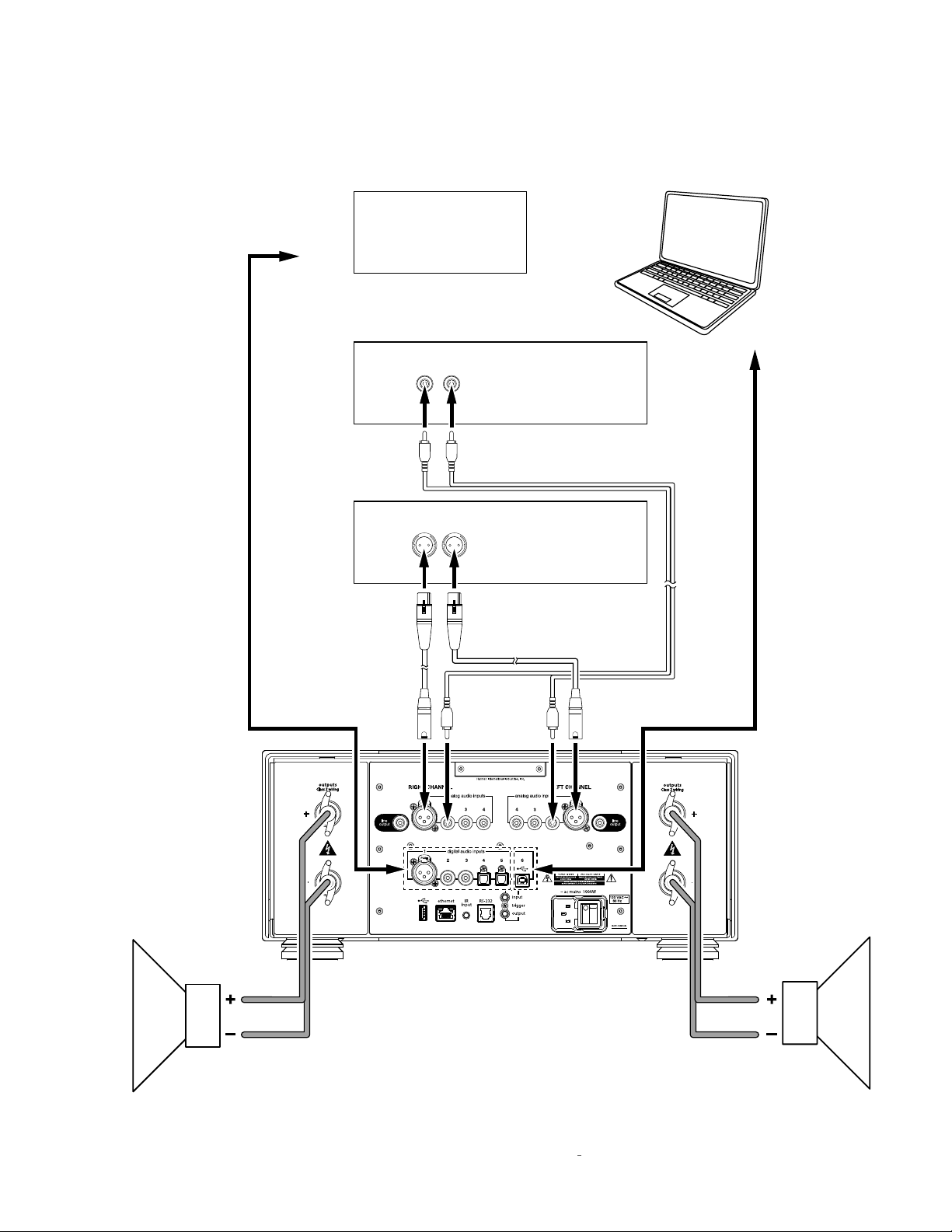
1. Connect your speakers to the N
0
585's loudspeaker
binding posts. Connect the speaker's positive (+) terminal
to the N
speaker's negative (–) terminal to the N
0
585's positive (+) red binding post, and the
0
585's negative
(–) black binding post.
CAUTION: Be careful to not short the positive and negative
outputs together. Do not short the positive or negative
outputs to chassis or any other safety ground.
2. If your system includes a powered subwoofer, connect it
to the N
as
0
585's Line outputs. (Configure the Line outputs
Variable
in the Setup menu. See the
N0585 User Guide
for details.)
3. Connect up to four line-level analog source components
to the N
0
585's analog audio inputs. One set of balanced
(XLR) connectors and three sets of single-ended (RCA)
connectors are available.
4. Connect up to six digital source components to the
0
N
585's digital audio inputs. One AES/EBU (XLR)
connector, two coaxial S/PDIF (RCA) connectors, two
optical S/PDIF (TOSLINK) connectors and one USB-B
connector are available.
5. Connect the supplied power cable to the N0585's AC
Mains connector and into an electrical outlet. Power on
0
the N
585 and all associated components.
6. Press the Standby button on the N
0
585's front panel or
remote control to turn it on.
7. Rotate the N
0
585 select knob or press the Select
+/– buttons on the remote to select the N
that corresponds to an input connector to which you
connected a source component.
8. Make sure the N
0
585’s volume is set to a reasonable
level. Then, begin playing the selected source device.
NOTE: After connecting all source components to
0
the N
585, we suggest using the Setup menu to
set the names of all inputs that have no connected
source components to “Unused.” This will remove the
unconnected inputs from the list of available inputs
and they will be skipped when selecting the active
input. See the
N0585 User Guide
for details.
0
585 input
12 N0585 INTEGRATED AMPLIFIER / QUICK-START GUIDE
Page 15
QUICK SETUP AND LISTEN
Digital Source
Component
To Digital
Output
Single-Ended
Analog Source
Component
Balanced
Analog Source
Component
Computer
To USB
Port
Right
Speaker
Left
Speaker
13N0585 INTEGRATED AMPLIFIER / QUICK-START GUIDE
Page 16

TROUBLESHOOTING
TROUBLESHOOTING
If the N0585 experiences a potentially damaging condition, its built-in protection circuitry will shut off the amplifier and its
Front-Panel Display will show one of the error messages listed below. Follow the instructions in the
correct the condition before attempting to use the N
0
585 again.
ERROR MESSAGE PROBLEM SOLUTION
Solution
column to
WARNING: DC DETECTED ON [LEFT/
RIGHT] CHANNEL
WARNING: OVER TEMP [LEFT/
RIGHT]
WARNING: OVER CURRENT ON
[LEFT/RIGHT] CHANNEL
• The indicated amplifier channel has
detected DC on the output which can
damage speakers.
• Indicated amplifier channel has exceeded
thermal limits.
• Indicated amplifier channel has exceeded
current limits.
• Set the rear-panel Power switch to off. Wait
10 seconds and turn the switch back on. If the
error message does not clear call your Mark
Levinson dealer or Mark Levinson customer
service.
• Put the N0585 into standby by pressing the
Standby button. Wait 10 to 15 minutes to let
the unit cool down and press the Standby
button again. If the error message does not
clear call your Mark Levinson dealer or Mark
Levinson customer service.
• Set the rear-panel Power switch to off. Wait
10 seconds and turn the switch back on. If the
error message does not clear set the Power
switch to off and disconnect the channel's
speaker wire from the N0585. Wait 10 seconds
and turn the Power switch back on. If the
error message does not clear call your Mark
Levinson dealer or Mark Levinson customer
service.
14 N0585 INTEGRATED AMPLIFIER / QUICK-START GUIDE
Page 17

SPECIFICATIONS
AMPLIFIER SECTION
Output Power: 200W RMS per channel @ 8 Ω, 20Hz – 20kHz
Damping Factor: >400 @ 20Hz, referred to 8 Ω
Frequency Response: 20Hz – 20kHz, ±0.13dB; 2Hz – 250kHz, +0.2dB/–3dB
SPECIFICATIONS
Signal-to-Noise Ratio: >98dB (20Hz – 20kHz, unweighted); >103dB (20Hz – 20kHz, A-wtd),
Voltage Gain: 40.7dB (maximum volume setting)
Total Harmonic Distortion: <0.01% @ 1kHz, 200W, 8 Ω; <0.1% @ 20kHz, 200W, 8 Ω
referred to full output – maximum volume setting
PREAMPLIFIER SECTION: ANALOG
Input Impedance: >45k Ω (RCA & XLR)
Input Overload: >5.5V RMS (RCA & XLR)
PREAMPLIFIER SECTION: DIGITAL
Sample Rates/Bit Depth (PCM): 32kHz, 44.1kHz, 48kHz, 88.2kHz, 96kHz, 176.4kHz, 192kHz/up to 32-bit
GENERAL
Analog Audio Connectors: 3 pairs single-ended inputs (RCA); 1 pair balanced inputs (XLR); 1 pair single-ended line outputs
Digital Audio Connectors: 1 balanced AES/EBU input (XLR); 2 coaxial S/PDIF inputs (RCA); 2 optical inputs (Tos-Link);
(RCA); 1 pair loudspeaker outputs ("Hurricane" binding posts w/banana sockets that accept spade
lugs with 1/4" (6.3mm) spacing up to 1/8" (3mm) thick)
1 asynchronous USB input (USB-B)
Control Connectors: 1 RS-232 port (RJ-12 connector); 1 IR input (1/8" phone jack); 1 programmable 12V DC trigger
output (1/8" phone jack), 100mA maximum; 1 programmable 12 DC trigger input (1/8" phone
jack); 1 Ethernet port (RJ-45 connector)
Mains Voltage: 100V AC, 115V AC, or 230V AC (factory-set)
Power Consumption: Maximum 1000W (power on)
Unit Dimensions (H x W x D): 6.9" (175mm) – without feet; 7.59" (193mm) – with feet x 17.25" (438mm) x 19.95" (507mm)
Packaging Dimensions (H x W x D): 19" (483mm) x 26" (660mm) x 26" (660mm)
Weight: 72 lb (32.6kg) – net; 96 lb (43.4kg) – with packaging
15N0585 INTEGRATED AMPLIFIER / QUICK-START GUIDE
Page 18

HARMAN International Industries, Incorporated
8500 Balboa Boulevard
Northridge, CA 91329 USA
© 2014 HARMAN International Industries, Incorporated. All rights reserved.
Mark Levinson is a registered trademark of HARMAN International Industries, Incorporated.
Other company and product names may be trademarks of the respective companies with which they
are associated.
This document should not be construed as a commitment on the part of HARMAN International
Industries, Incorporated. The information it contains, as well as the features, specifications and
appearance of the product, is subject to change without notice. HARMAN International Industries,
Incorporated, assumes no responsibility for errors that may appear within this document
For customer service and product shipment information, refer to our Web site: www.marklevinson.com
Part No. 070-22115 Rev: A www.marklevinson.com
 Loading...