


0
N
INTEGRATED AMPLIFIER OWNER’S MANUAL
585

TABLE OF CONTENTS / ABOUT THIS DOCUMENT
TABLE OF CONTENTS
About This Document 2
Special Design Features 3
Setup Menu 4
Setup Menu Navigation, Input Setup, Volume Control,
Power Management, Advanced, Output
SSP Setup 10
Troubleshooting 12
Specifications 16
ABOUT THIS DOCUMENT
This User Guide primarily covers the system functions and
advanced options contained in your N
guide also covers setup for SSP (Surround Sound Processor)
mode. These resources allow you to finely tailor the behavior
and performance of the N
particulars of your equipment and listening room.
Before you read this User Guide, we recommend that you
thoroughly read the
0
your N
585 in printed form. The
the information you will need to unpack and place your N
connect it to the rest of your audio system and have a first listen.
2 N0585 INTEGRATED AMPLIFIER / OWNER’S MANUAL
0
585 to fit your preferences and the
N0585 Quick-Start Guide,
0
585’s Setup menus. This
supplied with
Quick-Start Guide
contains all
0
585,
For the sake of brevity, instructions in this guide refer only to the
use of front-panel controls. Functions accomplished by using
the front-panel Select knob, Setup button, and Enter button
may also be accomplished using the remote-control Select +/buttons, Setup button, and Enter button.

SPECIAL DESIGN FEATURES
SPECIAL DESIGN FEATURES
Thank you for purchasing the N0585 integrated amplifier.
Combining Mark Levinson’s unsurpassed analog performance
with advanced digital audio capability and flexible system
configuration, the N
0
585 pushes the reproduction of any source
material to new levels of realism.
Architecture
The foundation of the N
0
585 is its fully-discrete, mirror-imaged,
dual-monaural analog circuitry featuring individual signal
switching relays for each of its four stereo inputs: one balanced
(XLR) and three single-ended (RCA). Volume controls use
discrete 15-bit R-2R ladders and low-noise analog switches for
the widest possible bandwidth and maximum signal integrity.
The fully-differential Class A/B power stage includes an
oversized 900VA toroidal transformer with individual secondary
windings for the left and right channels. Each elegantly simple
amplifier channel utilizes twelve output transistors and
multiple smaller local capacitors, which allows them to be
placed physically closer to the amplifiers for greater transient
response when power is needed immediately. This robust
architecture results in a conservative power rating of 200W per
channel. System integration and expansion are possible using
the stereo RCA preouts which can operate full-range or with
an included switchable, second-order, 80Hz crossover filter
allowing for seamless integration into 2.1-channel systems
with powered subwoofers.
Construction
The chassis of the N
0
585 utilizes card-cage architecture to
isolate critical low-level analog and digital circuitry from the
power supplies and amplifier modules. The steel and aluminum
construction features internal amplifier heatsinks and Mark
Levinson’s iconic black and silver anodized aluminum front
panel with its intuitive twin-knob control system and unique red
display.
Features
• Modular circuit design provides isolation of critical audio
circuitry subsections
• High-resolution 32-bit/192kHz D/A converter with
asynchronous USB input
• Patented Clari-Fi
™
signal processing for compressed audio
formats
• Fully-differential, Class A/B amplifier rated at 200W into
8 ohms
• Four analog audio inputs: One balanced (XLR) and three
single-ended (RCA) stereo pairs
• Six digital audio inputs: One USB, one AES/EBU, two coaxial
and two optical
ENGLISH
Audio Chassis
Building upon this superb analog platform, the N
0
585 adds
equally outstanding digital audio capability. An ESS Sabre 32bit D/A converter with proprietary jitter elimination circuitry and
fully-balanced, discrete I/V circuitry forms the heart of the digital
audio processing stage. Six digital audio inputs are provided
including one AES/EBU, two coaxial and two optical plus a
USB audio processor capable of asynchronous data transfer
of high resolution DSD and PCM files at up to 192kHz/32 bits
resolution. For low-resolution audio formats, proprietary ClariFi™ signal processing reconstructs information and bandwidth
lost in compressed file formats restoring them to higher fidelity.
System integration and communication ports include Ethernet,
USB, RS-232, IR input, and 12V trigger input and output. A
system IR remote control is included.
• Analog preouts with selectable 80Hz crossover filter for
2.1-channel capability
• System controls: Ethernet, RS-232, IR input, and 12V trigger
input and output
• IR remote control
• Software update via USB flash drive or Ethernet
3N0585 INTEGRATED AMPLIFIER / OWNER’S MANUAL
SETUP MENU
r
SETUP MENU
This section explains the use of the Setup menus on your N0585,
which allow you to customize and configure the unit.
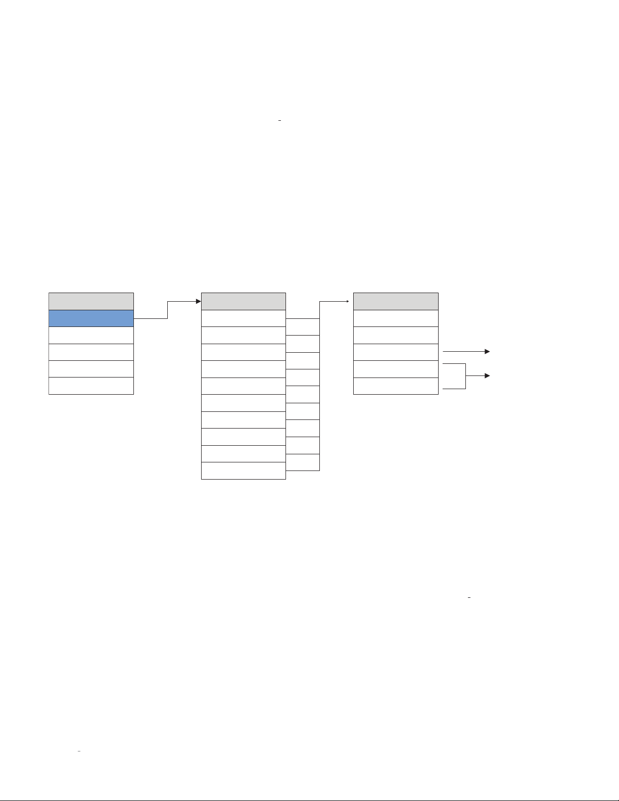
SETUP MENU NAVIGATION
Pressing the Setup button displays the Setup menu on the
integrated amplifier’s front-panel display. When the Setup
menu is active, use the Select knob to scroll through options,
the Enter button to select and deselect options, and the Volume
knob to adjust parameters. To move back a level in the menu
structure (or exit the Setup menu), press the Setup button
repeatedly until the desired menu is shown in the display.
INPUT SETUP
Setup Menu
Input Setup
Volume Control
Power Mgmt
Advanced
Output
Input Setup
Input 1 [XLR]
Input 2 [RCA1]
Input 3 [RCA2]
Input 4 [RCA3]
Input 6 [AES/EBU]
Input 7 [Coax1]
Input 8 [Coax2]
Input 9 [Opt1]
Input 10 [Opt2]
Input 11 [USB]
The Input Setup menu allows you to customize the following
parameters for the selected input:
The following settings are available for all inputs.
Name:
This option offers a choice of preset names for the
selected input (CD, SACD
[number], [Input type], [Input connector]. Additionally, the
following special names are available for each input:
Unused: This option removes the selected input from the list
of available inputs. The input will be skipped when selecting
the active input.
Manual Entry: This option allows you to enter a custom
name for the selected input. Use the Select knob to select
the character you want to change, use the Volume control
to choose from the list of available characters and press
the Enter button to confirm each character. After the eighth
character is entered, the new name will be saved.
™
, DVD, Blu-ray™, DAC, EQ, Input
Set Input X
Name=XXX
Offset=XXX
SSP=XXX
PCM Filter=XXX
Clari-Fi=XXX
Offset:
The output level of audio devices can vary from brand-tobrand and model-to-model, making some devices sound louder
or quieter than others. The Offset adjustment lets you precisely
compensate for that variance, allowing all associated devices in
your system to output at a similar volume level.
The setting offers a range of –12.0dB to +12.0dB, in 0.1dB steps,
Whenever an input is selected, the N
the Offset parameter to the volume level of the Speaker and
Line outputs.
SSP:
The SSP setting configures the selected input for complete
integration with a multichannel surround sound processor. See
SSP Setup
setting is only available for analog inputs.)
on page 10 for more information. (Note: The SSP
0
Available only for
analog inputs
Available only fo
digital inputs
585 applies the setting of
4 N0585 INTEGRATED AMPLIFIER / OWNER’S MANUAL

The following settings are available only for the digital inputs.
PCM Filter:
This setting lets you set the filter characteristic for
PCM content:
Fast: This filter has a steep roll-off characteristic that may be
better suited when listening to electric or electronic music.
Slow: This filter has a gradual roll-off characteristic that is
well suited to most types of music.
Mphas: This is a minimum-phase filter that may be better
suited when listening to acoustic music.
Although the above descriptions are offered as a guide, feel free
to set the PCM filter according to your own tastes.
SETUP MENU
ENGLISH
Clari-Fi™:
Setting this to ON activates the Clari-Fi circuitry
for the input. Clari-Fi analyzes compressed digital audio files
during playback and reconstructs much of what was lost in the
compression process. The Intensity control adjusts the amount
of reconstruction applied to the signal, and can be applied
according to your individual taste – there is no “correct” amount.
5N0585 INTEGRATED AMPLIFIER / OWNER’S MANUAL

SETUP MENU
VOLUME CONTROL
Setup Menu
Input Setup
Volume Control
Power Mgmt
Advanced
Volume Control
Max=XXX
Mute=XXX
Turn On=XXX
Taper=XXX
The Volume Control settings let you customize the action of the
0
N
585‘s Volume and Mute functions.
Max Vol:
This setting lets you set a maximum Speaker output
and Line output volume level setting in 0.1dB increments
between 40.0dB and 80.0dB. The factory default maximum
volume is 80.0dB.
Mute:
This setting lets you set the amount of Speaker output
and Line output level attenuation that occurs when the Mute
button is engaged, in 0.1dB increments between –10dB and
–80.0dB. The factory default mute attenuation is –40dB.
Turn On:
output volume level to which your N
This setting lets you set a Speaker output and Line
0
585 will default every time
you turn it on.
• 10.0dB – 60.0dB: Choose a turn-on volume level in 0.1dB
increments between 10.0db and 60.0db. The factory default
setting is 40.0dB.
• Last: The volume level setting from the previous time the
unit was powered down is retained.
CAUTION: Setting the Turn On parameter to Last can result in
louder-than-expected power-up volume if the N
0
585 was set to
a high volume level setting when last powered down.
Taper:
This setting lets you choose the desired taper for the
volume control, from the following options:
Mode 1: The faster you rotate the volume knob the more
quickly the volume will change. Rotating the knob slowly
slows the rate the volume changes, allowing you to make very
precise adjustments in the listening level.
Mode 2: Similar to Mode 1, with a “faster” response curve,
with more gain change for a similar range of knob travel.
Mode 3: When increasing the volume the volume changes
quickly through the low volume range, and then decelerates
in the higher range, for precision adjustments. When
decreasing the volume the control works in the opposite
fashion, changing quickly through the high volume range and
decelerating in the lower range.
6 N0585 INTEGRATED AMPLIFIER / OWNER’S MANUAL

POWER MANAGEMENT
SETUP MENU
Setup Menu
Input Setup
Volume Control
Power Mgmt
Power Mgmt
Standby=XXX
AutoOff=XXX
Display=XXX
Advanced
The Power Management parameters let you customize powerrelated functions.
Standby:
This setting lets you set the Standby mode to one of
the following options:
Green: This mode removes power from almost all of the
0
N
585s circuits, allowing the unit to be activated only via an
IR control signal, a 5V – 12V trigger voltage or a press of
the Standby button. This mode provides maximum power
conservation and is the factory-default Standby mode.
Power Save: This mode removes power from the N
0
585’s
audio circuits, but keeps the control circuitry powered and
ready to receive commands from either the front-panel
controls or the remote control. This mode provides moderate
power conservation.
Normal: This mode shuts off the N
0
585’s display and mutes
its audio outputs, but keeps all of its control and audio circuits
powered. This mode provides the least amount of power
conservation but allows the N
0
585’s audio circuits to remain
warmed up to deliver optimal performance at all times.
Auto Off:
Auto Off function, which puts your N
This setting lets you engage or disengage the
0
585 into the Standby mode
after 20 minutes of inactivity (no audio signal, and no usercontrol input).
Display:
This menu gives you access to the following display-
related parameters:
Intensity: Lets you set the brightness of your N
0
585’s display
and front-panel LEDs to High, Med, Low, or Off (which turns
the display and LEDs off entirely until a control is operated).
The factory default setting is High.
Timer (only applies when the display intensity is set to Off):
Lets you choose how long the display and LEDs remain lit
after the last time a control is operated. Choose from 10
seconds, 4 seconds, or 2 seconds. The factory default setting
is 10 seconds.
ENGLISH
7N0585 INTEGRATED AMPLIFIER / OWNER’S MANUAL

SETUP MENU
ADVANCED
Setup Menu
Input Setup
Volume Control
Power Mgmt
Advanced
Output
Advanced
Firmware
Connect
Config
Network
Trigger
Front IR
The Advanced section of the Setup menu gives you access
to a range of configuration and administrative settings and
functions.
Firmware:
This menu gives you access to the following
firmware-related functions:
Ver: Displays the version number of the currently loaded
firmware. (This setting is informational only, and does not
provide any user adjustments.)
Update: Lets you update your N
0
585’s firmware, either from
a flash drive inserted in the rear-panel USB port or from a
connected computer over the Ethernet connection. (If you
press Enter when ENET is selected, The N
0
585 ‘s display
shows “Start Download” to remind you to connect via a
browser and begin downloading the firmware.) To update via
a flash drive:
1. Select USB and press Enter.
2. The N
0
585 will read the USB drive. (The display will show
“Not Ready” while the drive is being read.)
3. When the N
0
585 finds a valid firmware file on the drive, the
display will show “Downloading.”
• If the N
0
585 does not find a valid firmware file on the
drive, the display will show “Not Available.”
Connect:
you made to your N
Config:
This menu lets you select the type of control connection
0
585: Ethernet, or RS232.
This menu lets you import or export Setup menu
configuration settings.
Export: Press Enter to export all setup configuration
information to a thumb drive inserted in the rear-panel USB
port. This data can then be used to identically configure
other N
reconfigure your N
0
585 units, or serve as a backup so you can easily
0
585.
Import: Press Enter to import all setup configuration
information from a thumb drive inserted in the rear-panel
USB port.
Lock: Engage the Lock to prevent accidental changing of
Setup menu parameters. The factory default setting is Off.
Restore: Lets you restore all N
0
585 parameters to their
factory-default condition.
Network:
This menu offers access to the following network-
related parameters:
Name: N
0
585_XXXXXX: Displays your N0585’s network name
(the X’s represent the last six digits of the unit’s unique MAC
address). This setting is informational only and does not
provide any user adjustments.
DHCP: Lets you toggle DHCP mode (network autoconfiguration) on or off. The factory default behavior is
On. When the mode is set to Off, you can specifiy static IP
and Subnet addresses for your N
0
585. Selecting Renew
(available only when DHCP is set to On) refreshes your DHCP
configuration, assigning a new IP address to your N
0
585.
This function is often useful when troubleshooting a network
connection.
Current IP: Shows the IP address currently assigned (by DHCP
or manually) to your N
0
585. (This setting is informational only
and does not provide any user adjustments.)
Current Subnet: Shows the subnet address currently
assigned (by DHCP or manually) to your N
0
585. (This
setting is informational only and does not provide any user
adjustments.)
Trigger:
This setting configures how the 12V trigger relay data
is sent and received. Most components require this to be set
at “Normal,” but some products (such as some older Mark
Levinson components) require that it be set to “Pulsed.”
Front IR:
receiver on or off. If you have connected the N
This menu allows you to turn the N0585’s front IR
0
585’s rear-panel
IR input to an IR control device, we recommend that you set the
Front IR receiver to Off to avoid interference.
8 N0585 INTEGRATED AMPLIFIER / OWNER’S MANUAL

OUTPUT
SETUP MENU
Setup Menu
Input Setup
Volume Control
Power Mgmt
High Pass
Line Out
PwrAmp
Output
Advanced
Output
The Output section of the Setup menu lets you configure the
0
N
585’s outputs.
High Pass:
Butterworth 80Hz high-pass filter on the N
This menu allows you to activate a 12dB/octave
0
585’s speaker
outputs. If you have connected a powered subwoofer to the
0
N
585’s Line Outputs and want to restrict the low frequencies
sent to your system’s main speakers, set the Hi Pass filter to On.
Line Out:
This menu lets you set the N0585’s Line Outputs to
Fixed or Variable:
Fixed: Use this setting when you have connected the Line
Outputs to a recording device. The Line Outputs will remain
at a fixed level regardless of the N
0
585’s volume control level.
Variable: Use this setting when you have connected the Line
Outputs to a powered subwoofer or to an external amplifier.
The Line Output level will vary with the level of the N
0
585’s
volume control.
PwrAmp:
power amplifier, such as when you are using your N
This menu lets you enable or disable the N0585’s
0
585 in a
multi-zone system or with an upgraded power amplifier.
ENGLISH
9N0585 INTEGRATED AMPLIFIER / OWNER’S MANUAL

SSP SETUP
SSP SETUP
In the past, the differing number of channels in each component
made integration between two-channel and multichannel
components difficult. Sending multichannel processor output
signals to a stereo Preamplifier distorts calibrated processor
output levels. Multichannel processor volume controls adjust
the relative volume level of all channels in unison. However,
stereo Preamplifier volume controls adjust the relative volume
level of just the front left and right channels, leaving the center,
surround, and subwoofer channels unaffected.
To avoid these problems when the N
0
585 is connected with an
associated surround-sound processor, the SSP mode allows
selected input sources to pass through the N
interference. When SSP mode is activated the N
control is deactivated to prevent the N
0
0
585 without
0
585 volume
585 from distorting
channel balance. As a result, the processor controls the relative
volume level of all channels while maintaining its calibrated
output levels.
To connect the N
0
585 with a surround-sound processor (see
illustration on next page):
1. Make sure the N
0
585 and all associated components are
powered off and disconnected from electrical outlets.
2. Connect the output connectors on the surround-sound source
component to the input connectors on the surround-sound
processor. For example, if the source component is a Blu-ray
disc player, connect it to the appropriate input connectors on
the surround-sound processor.
3. Connect the front left and right output connectors on the
processor to the desired input connectors on the N
0
585.
For best performance, use balanced connections whenever
possible.
4. Connect the center, surround, and subwoofer output
connectors on the processor to the appropriate input
connectors on the power amplifier(s).
5. Connect the N
0
585’s speaker outputs to the system’s front left
and right (main) speakers.
To activate the SSP mode for a selected input:
CAUTION: Before activating the SSP mode for any input, set
the associated surround sound processor volume control to a
reasonable level to prevent sending dangerous signal levels to
the associated loudspeakers.
1. Activate the Setup menu by pressing the Setup button.
2. Select Input Setup, and press Enter.
3. Select the input you wish to configure for SSP use, and press
Enter.
4. Select SSP, and press Enter.
5. Set the SSP parameter to On.
6. Press the Setup button four times to step backward through
the menu hierarchy and exit the Setup menu.
10 N0585 INTEGRATED AMPLIFIER / OWNER’S MANUAL

SURROUNDSOUND
SOURCE DEVICE
SSP SETUP
Analog OutputDigital Output
OpticalCoaxial RL
ENGLISH
SURROUNDSOUND
PROCESSOR
N0585
INTEGRATED AMPLIFIER
312
312
122
43
Front
Left
S-Video Inputs
3
645
Analog Audio In 1 Analog Audio In 2
Center
Y/G
312
645
Digital Audio Inputs
3
1
RR
LL
Subwoofer 1 Subwoofer 2
Right
Left
1
Pb/B Pr/R
12
Composite Video Inputs Component Video Inputs
Microphone Inputs
12
Analog Audio Outputs
Right
HDMI OutputsHDMI Inputs
ASE/EBU Inputs
12
Right
2
Y/G
Monitor
Out
Analog Audio Inputs
3
L
R
Left
Pb/B Pr/R
Component Video Output
Y
4
Right
Pb
Link
56
L
R
Surround
Trigger Outputs
7.1 Channel Input
CTR SL
Right
Surround
Back
Y/G
RS-232
SR BR
Left
4
Pb/B Pr/R
BL
AC Input
Ethernet
Remote Zone
Left
Right
3
Pb/B Pr/R
Y/G
Pr
IR Input
FL
FR SUB
Left
To Front
Left & Right
Speakers
CENTER & SURROUND
POWER AMPLIFIER
To Center &
Surround
Speakers
balanced
single ended
outputs
balanced
inputs
inputs
single ended
outputs
balanced
inputs
single ended
outputs
11N0585 INTEGRATED AMPLIFIER / OWNER’S MANUAL

TROUBLESHOOTING
TROUBLESHOOTING
Incorrect operation is sometimes mistaken for malfunction. If problems occur, see this section for troubleshooting information.
If problems persist, contact your authorized Mark Levinson dealer.
NO POWER
Examine the power cord to ensure that it is connected to both the AC mains connector and a working,
Make sure the N0585 is powered on with the rear-panel Power switch.
Examine the electrical circuit breaker to ensure that power is being supplied to the electrical outlet to which the N0585 is connected.
Make sure the N0585 is
when the N0585 is in Standby mode.
not
in standby. The front-panel standby LED illuminates fully and continually when the N0585 is On. The LED flashes slowly
unswitched
electrical outlet.
REMOTE CONTROL DOES NOT OPERATE
Eliminate obstructions between the remote control IR transmitter and the IR receiver on the front-panel display.
Make sure the rear-panel IR input connector is
Make sure the remote control is positioned within 17 feet (5m) of the Controller’s front panel. If the Controller chassis is placed inside a glass
cabinet, tinted glass will reduce the remote control range.
Make sure the remote control signal is being received at the IR receiver on the Controller’s front-panel display at a reasonable angle.
Make sure the IR receiver on the Controller’s front-panel display is not exposed to strong sunlight, halogen light, or fluorescent light. This can
cause IR reception to become unreliable.
Replace the remote control batteries.
not
being used.
NO SIGNAL AT THE SPEAKER OR LINE OUTPUTS
Examine all audio cables to ensure a solid connection between the N0585 and all associated components.
Examine the speaker cables to ensure a solid connection between the N0585 and the speakers.
Make sure that the connected speakers are operational.
Make sure the volume is set to an audible level.
Make sure the mute is deactivated.
Make sure the Offset setting for the selected input is not reducing the volume to an inaudible level.
Make sure all associated components are connected to working electrical outlets and powered on.
Make sure the source device connected to the selected N0585 input is producing an output signal.
“MISSING” INPUT
Make sure the Name parameter for the selected input has not been set to Unused in the Setup menu.
12 N0585 INTEGRATED AMPLIFIER / OWNER’S MANUAL

AUDIO HAS A HUMMING SOUND
TROUBLESHOOTING
Disconnect components one at a time to isolate the problem.
Once the problem is identified, make sure the problematic component is properly grounded and connected to the same electrical circuit as
the N0585.
VOLUME CAN’T BE SET TO MAXIMUM
You have the option of establishing a maximum volume level in the Setup menu. If this option is set, it can prevent the N0585’s maximum volume
level of 80.0 from being reached. Refer to
Volume Control / MaxVol
on page 6 for more information.
FRONTPANEL DISPLAY NOT WORKING
Verify that the Intensity parameter in the Setup menu is not set to Off.
NO CONNECTIVITY VIA ETHERNET
Verify that the network cables are properly connected between the router, switch or hub and the N0585.
Verify the age of the router, switch or hub. If the router, switch or hub is more than ten years old, there may be a communication issue with the
N0585. Power cycle the N0585 and use a newer router, switch or hub between the network and the N0585.
IF ALL ELSE FAILS…
Power cycle the N0585 with the rear-panel Power switch, waiting at least 10 seconds between powering the N0585 off and on.
ENGLISH
Restore factory-default settings (See
Contact your authorized Mark Levinson dealer.
Contact Mark Levinson Customer Service at 888-691-4171 or www.marklevinson.com.
Advanced: Config / Restore
on page 8).
13N0585 INTEGRATED AMPLIFIER / OWNER’S MANUAL

SPECIFICATIONS
SPECIFICATIONS
AMPLIFIER SECTION
Output Power: 200W RMS per channel @ 8 Ω, 20Hz – 20kHz
Damping Factor: >400 @ 20Hz, referred to 8 Ω
Frequency Response: 20Hz – 20kHz, ±0.13dB; 2Hz – 250kHz, +0.2dB/–3dB
Signal-to-Noise Ratio: >98dB (20Hz – 20kHz, unweighted); >103dB (20Hz – 20kHz, A-wtd),
Voltage Gain: 40.7dB (maximum volume setting)
Total Harmonic Distortion: <0.01% @ 1kHz, 200W, 8 Ω; <0.1% @ 20kHz, 200W, 8 Ω
referred to full output – maximum volume setting
PREAMPLIFIER SECTION: ANALOG
Input Impedance: >45k Ω (RCA & XLR)
Input Overload: >5.5V RMS (RCA & XLR)
PREAMPLIFIER SECTION: DIGITAL
Sample Rates/Bit Depth: PCM: 32kHz, 44.1kHz, 48kHz, 88.2kHz, 96kHz, 176.4kHz, 192kHz/up to 32-bit;
DSD: Native, single- and double-speed
GENERAL
Analog Audio Connectors: 3 pairs single-ended inputs (RCA); 1 pair balanced inputs (XLR); 1 pair single-ended line outputs (RCA); 1
Digital Audio Connectors: 1 balanced AES/EBU input (XLR); 2 coaxial S/PDIF inputs (RCA); 2 optical inputs (Tos-Link);
pair loudspeaker outputs ("Hurricane" binding posts w/banana sockets that accept spade lugs with 1/4"
(6.3mm) spacing up to 1/8" (3mm) thick)
1 asynchronous USB input (USB-B)
Control Connectors: 1 RS-232 port (RJ-12 connector); 1 IR input (1/8" phone jack); 1 programmable 12V DC trigger output (1/8"
Mains Voltage: 100V AC, 115V AC, or 230V AC (factory-set)
Power Consumption: Maximum 1000W (power on)
Unit Dimensions (H x W x D): 6.9" (175mm) – without feet; 7.59" (193mm) – with feet x 17.25" (438mm) x 19.95" (507mm)
Packaging Dimensions (H x W x D): 19" (483mm) x 26" (660mm) x 26" (660mm)
Weight: 72 lb (32.6kg) – net; 96 lb (43.4kg) – with packaging
14 N0585 INTEGRATED AMPLIFIER / OWNER’S MANUAL
phone jack), 100mA maximum; 1 programmable 12 DC trigger input (1/8" phone jack); 1 Ethernet port (RJ45 connector)

ENGLISH
15N0585 INTEGRATED AMPLIFIER / OWNER’S MANUAL

HARMAN International Industries, Incorporated
8500 Balboa Boulevard
Northridge, CA 91329 USA
© 2014 HARMAN International Industries, Incorporated. All rights reserved.
Mark Levinson is a registered trademark of HARMAN International Industries, Incorporated.
Blu-ray is a trademark of the Blu-ray Disc Association.
SACD (Super Audio CD) is a trademark of Sony Corporation.
Other company and product names may be trademarks of the respective companies with which they
are associated.
This document should not be construed as a commitment on the part of HARMAN International
Industries, Incorporated. The information it contains, as well as the features, specifications and
appearance of the product, is subject to change without notice. HARMAN International Industries,
Incorporated, assumes no responsibility for errors that may appear within this document.
For customer service and product shipment information, refer to our Web site: www.marklevinson.com
Part No. 070-90019 Rev: A.0 www.marklevinson.com
 Loading...